EP2656964A1 - Fil de soudage plein et métal de soudage - Google Patents
Fil de soudage plein et métal de soudage Download PDFInfo
- Publication number
- EP2656964A1 EP2656964A1 EP10860903.3A EP10860903A EP2656964A1 EP 2656964 A1 EP2656964 A1 EP 2656964A1 EP 10860903 A EP10860903 A EP 10860903A EP 2656964 A1 EP2656964 A1 EP 2656964A1
- Authority
- EP
- European Patent Office
- Prior art keywords
- welding
- rem
- weld
- weld metal
- metal
- Prior art date
- Legal status (The legal status is an assumption and is not a legal conclusion. Google has not performed a legal analysis and makes no representation as to the accuracy of the status listed.)
- Withdrawn
Links
Images
Classifications
-
- B—PERFORMING OPERATIONS; TRANSPORTING
- B23—MACHINE TOOLS; METAL-WORKING NOT OTHERWISE PROVIDED FOR
- B23K—SOLDERING OR UNSOLDERING; WELDING; CLADDING OR PLATING BY SOLDERING OR WELDING; CUTTING BY APPLYING HEAT LOCALLY, e.g. FLAME CUTTING; WORKING BY LASER BEAM
- B23K35/00—Rods, electrodes, materials, or media, for use in soldering, welding, or cutting
- B23K35/22—Rods, electrodes, materials, or media, for use in soldering, welding, or cutting characterised by the composition or nature of the material
- B23K35/24—Selection of soldering or welding materials proper
- B23K35/30—Selection of soldering or welding materials proper with the principal constituent melting at less than 1550°C
- B23K35/3053—Fe as the principal constituent
- B23K35/3066—Fe as the principal constituent with Ni as next major constituent
-
- B—PERFORMING OPERATIONS; TRANSPORTING
- B23—MACHINE TOOLS; METAL-WORKING NOT OTHERWISE PROVIDED FOR
- B23K—SOLDERING OR UNSOLDERING; WELDING; CLADDING OR PLATING BY SOLDERING OR WELDING; CUTTING BY APPLYING HEAT LOCALLY, e.g. FLAME CUTTING; WORKING BY LASER BEAM
- B23K35/00—Rods, electrodes, materials, or media, for use in soldering, welding, or cutting
- B23K35/02—Rods, electrodes, materials, or media, for use in soldering, welding, or cutting characterised by mechanical features, e.g. shape
- B23K35/0255—Rods, electrodes, materials, or media, for use in soldering, welding, or cutting characterised by mechanical features, e.g. shape for use in welding
- B23K35/0261—Rods, electrodes or wires
-
- B—PERFORMING OPERATIONS; TRANSPORTING
- B23—MACHINE TOOLS; METAL-WORKING NOT OTHERWISE PROVIDED FOR
- B23K—SOLDERING OR UNSOLDERING; WELDING; CLADDING OR PLATING BY SOLDERING OR WELDING; CUTTING BY APPLYING HEAT LOCALLY, e.g. FLAME CUTTING; WORKING BY LASER BEAM
- B23K9/00—Arc welding or cutting
- B23K9/02—Seam welding; Backing means; Inserts
- B23K9/025—Seam welding; Backing means; Inserts for rectilinear seams
-
- B—PERFORMING OPERATIONS; TRANSPORTING
- B23—MACHINE TOOLS; METAL-WORKING NOT OTHERWISE PROVIDED FOR
- B23K—SOLDERING OR UNSOLDERING; WELDING; CLADDING OR PLATING BY SOLDERING OR WELDING; CUTTING BY APPLYING HEAT LOCALLY, e.g. FLAME CUTTING; WORKING BY LASER BEAM
- B23K9/00—Arc welding or cutting
- B23K9/02—Seam welding; Backing means; Inserts
- B23K9/035—Seam welding; Backing means; Inserts with backing means disposed under the seam
-
- B—PERFORMING OPERATIONS; TRANSPORTING
- B23—MACHINE TOOLS; METAL-WORKING NOT OTHERWISE PROVIDED FOR
- B23K—SOLDERING OR UNSOLDERING; WELDING; CLADDING OR PLATING BY SOLDERING OR WELDING; CUTTING BY APPLYING HEAT LOCALLY, e.g. FLAME CUTTING; WORKING BY LASER BEAM
- B23K9/00—Arc welding or cutting
- B23K9/16—Arc welding or cutting making use of shielding gas
- B23K9/173—Arc welding or cutting making use of shielding gas and of a consumable electrode
-
- B—PERFORMING OPERATIONS; TRANSPORTING
- B23—MACHINE TOOLS; METAL-WORKING NOT OTHERWISE PROVIDED FOR
- B23K—SOLDERING OR UNSOLDERING; WELDING; CLADDING OR PLATING BY SOLDERING OR WELDING; CUTTING BY APPLYING HEAT LOCALLY, e.g. FLAME CUTTING; WORKING BY LASER BEAM
- B23K9/00—Arc welding or cutting
- B23K9/23—Arc welding or cutting taking account of the properties of the materials to be welded
-
- C—CHEMISTRY; METALLURGY
- C22—METALLURGY; FERROUS OR NON-FERROUS ALLOYS; TREATMENT OF ALLOYS OR NON-FERROUS METALS
- C22C—ALLOYS
- C22C38/00—Ferrous alloys, e.g. steel alloys
- C22C38/002—Ferrous alloys, e.g. steel alloys containing In, Mg, or other elements not provided for in one single group C22C38/001 - C22C38/60
-
- C—CHEMISTRY; METALLURGY
- C22—METALLURGY; FERROUS OR NON-FERROUS ALLOYS; TREATMENT OF ALLOYS OR NON-FERROUS METALS
- C22C—ALLOYS
- C22C38/00—Ferrous alloys, e.g. steel alloys
- C22C38/04—Ferrous alloys, e.g. steel alloys containing manganese
-
- C—CHEMISTRY; METALLURGY
- C22—METALLURGY; FERROUS OR NON-FERROUS ALLOYS; TREATMENT OF ALLOYS OR NON-FERROUS METALS
- C22C—ALLOYS
- C22C38/00—Ferrous alloys, e.g. steel alloys
- C22C38/08—Ferrous alloys, e.g. steel alloys containing nickel
-
- B—PERFORMING OPERATIONS; TRANSPORTING
- B23—MACHINE TOOLS; METAL-WORKING NOT OTHERWISE PROVIDED FOR
- B23K—SOLDERING OR UNSOLDERING; WELDING; CLADDING OR PLATING BY SOLDERING OR WELDING; CUTTING BY APPLYING HEAT LOCALLY, e.g. FLAME CUTTING; WORKING BY LASER BEAM
- B23K2103/00—Materials to be soldered, welded or cut
- B23K2103/02—Iron or ferrous alloys
- B23K2103/04—Steel or steel alloys
-
- B—PERFORMING OPERATIONS; TRANSPORTING
- B23—MACHINE TOOLS; METAL-WORKING NOT OTHERWISE PROVIDED FOR
- B23K—SOLDERING OR UNSOLDERING; WELDING; CLADDING OR PLATING BY SOLDERING OR WELDING; CUTTING BY APPLYING HEAT LOCALLY, e.g. FLAME CUTTING; WORKING BY LASER BEAM
- B23K35/00—Rods, electrodes, materials, or media, for use in soldering, welding, or cutting
- B23K35/22—Rods, electrodes, materials, or media, for use in soldering, welding, or cutting characterised by the composition or nature of the material
- B23K35/38—Selection of media, e.g. special atmospheres for surrounding the working area
- B23K35/383—Selection of media, e.g. special atmospheres for surrounding the working area mainly containing noble gases or nitrogen
Definitions
- the present invention relates to an iron-based welding solid wire suitable for welding of 9% Ni steel (9% nickel steel) for ultralow-temperature service, and to weld metal of a weld joint between 9% Ni steel pieces.
- the weld joint between 9% Ni steel pieces may be simply referred to as "joint”.
- 9% Ni steel is high-tensile steel used at ultralow temperature of about -196°C, and has high yield strength and excellent low-temperature toughness.
- the 9% Ni steel is therefore widely used, as ultralow-temperature steel, for storage tanks for, for example, LNG, liquid nitrogen, and liquid oxygen, or various types of associated equipment thereof.
- a weld metal of a weld joint formed by welding between 9% Ni steel pieces is naturally required to have substantially the same properties of, such as ultralow-temperature toughness, as those of the base metal.
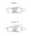
- Fig. 1 illustrates an example of a flash butt weld joint (welding test example) between 9% Ni steel plates.
- a weld metal 3 of a weld joint 1a between 9% Ni steel plates 2a and 2b is formed through the same process of sequential formation of deposition beads (1) to (13) in a multilayered manner with high heat input.
- a symbol 5 indicates a backing metal.
- a relatively small amount of deposition is made so that a thin bead is produced; hence, for example, a bead (12) is completely reversely transformed by, for example, a subsequent bead (13).
- a relatively coarse unaffected zone (solidified structure) of each deposition layer is transformed into a fine reheated structure.
- a structure of a lower layer is refined due to an appropriate heat treatment effect caused by a heat cycle during welding of an upper layer, leading to improvement in low-temperature toughness of the lower layer.
- a welding wire of a Ni-based alloy having the Ni content of as high as about 60% has been mainly used for welding of 9% Ni steel by highly efficient MIG welding.
- the weld joint formed with such a Ni-based alloy welding wire exhibits excellent toughness even at -196°C in the as-welded condition, which is however extremely low in tensile strength, particularly in 0.2% yield strength, compared with a 9% Ni steel base metal.
- design stress must be reduced due to the low strength of the weld joint. Consequently, thickness of a welded structure as a whole must be disadvantageously increased to secure certain strength of the weld joint.
- the Ni-based alloy welding wire As long as the Ni-based alloy welding wire is used, the high strength of 9% Ni steel is not sufficiently used, which inevitably leads to multiple loads or burdens such as an increase in thickness and in weight of a welded structure, and an increase in consumption of the expensive Ni-based alloy welding wire.
- the Ni-based alloy welding wire if welding is performed using the Ni-based alloy welding wire, there inevitably occurs a problem of hot crack associated with Ni, and a problem of thermal fatigue that is caused by a difference in thermal expansion coefficient between the Ni-based alloy welding wire and the 9% Ni steel base metal during welding due to a significant difference in composition therebetween.
- PTL1 discloses a method of improving the ultralow-temperature property by adjusting and/or limiting, within an appropriate range, the content of each of nickel, manganese, boron, and oxygen in a chemical composition of the similar-metal-composition welding wire for 9% Ni steel.
- PTL1 reports results of improvement in low-temperature toughness of a weld joint evaluated by the Charpy impact test in accordance with JIS-Z-3111, which is however evaluated only in terms of the entire absorbed energy. In other words, no investigation is made in terms of crack initiation strength.
- PTL2 proposes a method of improving low-temperature toughness of a weld joint through designing a welding operation process using the similar-metal-composition welding wire for 9% Ni steel. Specifically, PTL2 discloses a method where the surface of a final-layer weld bead in multilayer welding is cooled to 150°C or less, and then the surface of the final-layer weld bead is remelted by arc from a non-consumable electrode while being shielded by an inert gas. This method is intended to improve the low-temperature toughness by applying heat treatment to the final layer in a groove center through remelting of the final layer that is less likely to receive a heat treatment effect due to the heat cycle during welding of an upper layer.
- PTL3 proposes a technique for improving low-temperature toughness through control of carbide morphology and decrease of heat treatment time of a weld bead portion in welding using the similar-metal-composition welding wire for 9% Ni steel.
- a similar-metal-composition welding wire is used in Example, where the welding wire contains 0.042% or more REM (Rare Earth Metal) added thereto though there is no description is made on the reason why REM is added.
- the technique also causes an increase in number of steps due to the heat treatment required after welding as in PTL2, which in turn causes an increase in cost.
- wire compositions are not sufficiently investigated.
- the low temperature toughness required in light of the crack-initiation resistance strength is also not considered.
- REM refers to Rare Earth Metal, and is a general term of elements of La to Lu in the periodic table.
- a test method of ultralow-temperature toughness includes an instrumented Charpy impact test method, which provides a load displacement curve that allows separation between crack initiation and a crack propagation process during a Charpy impact test.
- This measurement method allows measurement of a toughness value (absorbed energy) Ei at crack initiation under application of external force, measurement of a toughness value (absorbed energy) Ep during crack propagation from the start to the end of a crack, and measurement of the crack-initiation resistance strength (the maximum load).
- the total toughness value Et (Ei+Ep) of Ei and Ep and the above-described crack-initiation resistance strength enable more detailed evaluation of ultralow-temperature toughness in correspondence to large-size brittle fracture strength of an actual welded structure.
- the technology of PTL4 improves the ultralow-temperature toughness particularly by adding Cr (chromium).
- Cr chromium
- a lower layer in the center of a weld metal in a groove is subjected to a heat treatment effect caused by a heat cycle during previous welding of an upper layer.
- a heat treatment effect caused by a heat cycle during previous welding of an upper layer.
- the structure of the weld metal is easily refined.
- Cr has an excellent function of reducing the ferrite-austenite transformation temperature.
- the technology of PTL5 improves the ultralow-temperature toughness particularly by adding REM.
- oxides extremely degrade the low-temperature toughness; hence, it is not preferable to form a large number of large oxides in the weld metal of the joint between 9% Ni steel pieces. If, however, an oxide, which is formed through a reaction with a small amount of oxygen in the weld metal, is sufficiently small, such an oxide does not serve as an initiation site of fracture, but rather advantageously serves as a pinning grain that inhibits crystal grain growth during or after solidification of weld. Consequently, a fine oxide effectively improves strength and toughness of the entire weld metal at low temperature.
- REM is determined to be optimum as an element having such an effect, and a specified amount of REM is contained in the similar-metal-composition welding wire to disperse an appropriate amount of fine oxides of REM in the weld metal.
- the REM oxides each have a property of good wettability to a melted iron alloy compared with other metal oxides, for example, Al oxides. As a result, even if the REM oxides are formed in a liquid phase of the weld metal, the oxides are less likely to agglomerate and thus do not grow into larger grains.
- each of the oxides serves as the pinning grain that inhibits the crystal grain growth during or after solidification of weld. Consequently, the REM oxides effectively improve strength and toughness of the entire weld metal at low temperature.
- PTL6 proposes a technology that allows a specified amount of REM to be contained in the similar-metal-composition welding wire.
- REM and Ga are added in combination, and a ratio of REM amount to Ca amount is controlled to be within a fixed range to stabilize arc in pure Ar gas.
- welding of the storage tank for low temperature service or associated equipment thereof is desirably performed by gas shield arc welding with high working efficiency without being limited to low efficient TIG welding.
- a MIG welding process for example, a plasma MIG welding process and a coaxial multilayered wire welding process
- an inert gas as a shield gas
- the MIG welding process is also suitable in light of such a need.
- Excessive content of oxygen in the weld metal of the joint causes an increase in number density of oxides, and/or coarsening of the oxides due to agglomeration or coalescence thereof, resulting in significant degradation in the ultralow-temperature toughness.
- the weld joint between 9% Ni steel pieces does not satisfy the reference value for each of the vE-196°C measured by the instrumented Charpy impact test method and the crack-initiation resistance strength.
- gas shield arc welding is typically performed using one of shield gases of pure Ar (argon) gas, Ar gas mixed with about 2 to 5% CO 2 (carbon dioxide), and Ar gas mixed with as much as about 20% CO 2 (80% Ar-20% CO 2 welding is in general referred to as MAG welding).
- Ar Ar
- MAG welding Ar gas mixed with as much as about 20% CO 2
- each shield gas containing carbon dioxide provides oxygen from the carbon dioxide, which prevents decrease of oxygen amount in the weld metal. This results in an excessively large amount of oxygen in the weld metal, and consequently the certain ultralow-temperature toughness cannot be secured as described above.
- pure Ar is used as the shield gas in the gas shield arc welding process in order to reduce the oxygen amount in the weld metal formed in the weld joint between 9% Ni steel pieces.
- pure Ar containing no carbon dioxide is used as the shield gas in such a way, the oxygen amount in the weld metal is reduced, and the ultralow-temperature toughness is improved.
- this causes a new problem of deterioration in bead shape of the weld joint between 9% Ni steel pieces.
- Fig. 2 illustrates an example of a flash butt weld joint between 9% Ni steel pieces while its bead shape is degraded.
- Fig. 2 illustrates a weld joint 1b between 9% Ni steel plates 2a and 2b formed by MIG welding, where a bead of a weld metal 4 has a greatly upwardly expanded, convex shape as illustrated in Fig. 2 , and a lateral border of the weld metal 4 is connected to the surface of each of the 9% Ni steel plates 2a and 2b through discontinuous inflection points (bents), which is technically known as overlap.
- discontinuous inflection points (bents)
- an excellent (normal) bead shape is an upwardly expanded convex bead as illustrated in Fig. 1 , in which the bead is smooth and low in height, and the lateral border of the weld metal 4 is smoothly and continuously connected to the surface of each of the 9% Ni steel plates 2a and 2b.
- the excellent (normal) bead shape is an arcuately curved concave shape that is downwardly and sequentially dented in a weld bead portion at a corner (L-shaped portion) of the weld joint, in which a lateral border of a weld metal is also smoothly and continuously connected to the surface of each 9% Ni steel plate.
- the lateral border of weld metal is not connected to the surface of each 9% Ni steel plate through the discontinuous inflection points (bents). Consequently, the fatigue strength of the weld joint is not reduced, and thus reliability of the weld joint is secured.
- Such a poor convex bead shape appears not only in a partial or entire section of the weld joint, but also over the entire longitudinal line of the weld bead portion of the weld joint.
- the normal (excellent) bead shape must be secured over the entire longitudinal line of the weld bead portion of the weld joint in order to secure the fatigue strength and reliability of the weld joint.
- the typical MIG welding process using the shield gas containing carbon dioxide wettability of a bead is improved by the effect of oxygen from the carbon dioxide, resulting in an excellent bead shape. This eliminates the need of the downstream step (operation) to correct the bead shape into an excellent shape by polishing and cutting.
- the typical MIG welding process uses the shield gas containing carbon dioxide to secure an excellent bead shape of the weld joint.
- control for forming the excellent bead shape which requires a certain amount of oxygen
- control for improving the ultralow-temperature toughness of the joint which requires regulation of oxygen.
- control operations are inconsistent in oxygen supply, and are therefore difficult to be achieved together.
- MIG welding is performed with pure Ar gas as a shield gas, and REM and Ca are added in combination to stabilize arc as described above, which allows decrease of number of defects within the weld metal.
- Ca is also an element that easily forms oxides, and is likely to cause a poor bead shape in MIG welding with pure Ar gas as a shield gas.
- excessive addition of Ca causes degradation in low-temperature toughness.
- the poor convex bead shape may appear over the longitudinal line (in a welding direction) of the weld bead portion of the joint regardless of configurations of the joint or welding positions. Moreover, as described above, such a poor bead shape more easily appears in MIG welding with pure Ar containing no carbon dioxide as a shield gas to reduce the amount of oxygen for improving the ultralow-temperature toughness.
- An object of the invention which is made in light of such problems, is to provide a welding solid wire that allows welding between 9% Ni steel pieces by a highly efficient gas shield arc welding process such as MIG welding, and a weld metal of a joint formed with such a welding solid wire.
- a welding solid wire of the invention is summarized by containing, in percent by mass, C: 0.10% or less (0% is not included), Si: 0.15% or less (0% is not included), Mn: 0.1 to 0.8%, Ni: 8.0 to 15.0%, REM: 0.005 to 0.040%, and O: 0.0020 to 0.0150%, where a mass ratio [REM]/[O] of REM to O is within a range of 2.5 to 4.2, and further containing Al and Ti each being regulated to be 0.03% or less (0% is included), with the remainder consisting of Fe and inevitable impurities.
- the mass ratio [REM]/[O] of REM to O is preferably within a range of 3.1 to 4.2.
- the welding solid wire is preferably used for gas shield arc welding of 9% Ni steel, in which one of pure argon gas and argon gas containing less than 2% (0% is not included) carbon dioxide is used as a shield gas.
- a weld metal of the invention is summarized by a weld metal of a weld joint between 9% Ni steel pieces, the weld metal containing, in percent by mass, C: 0.10% or less (0% is not included), Si: 0.15% or less (0% is not included), Mn: 0.1 to 0.8%, Ni: 8.0 to 15.0%, REM: 0.005 to 0.040%, and O: 0.0150% or less (0% is not included), and further containing Al and Ti each being regulated to be 0.03% or less (0% is included), with the remainder consisting of Fe and inevitable impurities, wherein when a sectional structure of the weld metal is observed by SEM of 1000 magnifications, average number of oxides having a maximum diameter of 0.1 to less than 1 ⁇ m is 1 ⁇ 10 3 to 5.0 ⁇ 10 3 per a visual field of 1mm 2 .
- the weld metal is formed by gas shield arc welding between the 9% Ni steel pieces with a welding solid wire and a shield gas, where the welding solid wire contains, in percent by mass, C: 0.10% or less (0% is not included), Si: 0.15% or less (0% is not included), Mn: 0.1 to 0.8%, Ni: 8.0 to 15.0%, REM: 0.005 to 0.040%, and O: 0.0020 to 0.0150%, where a mass ratio [REM]/[O] of REM to O is within a range of 2.5 to 4.2, and further contains Al and Ti each being regulated to be 0.03% or less (0% is included), with the remainder consisting of Fe and inevitable impurities, and the shield gas is preferably one of pure argon gas and argon gas containing less than 2% (0% is not included) carbon dioxide.
- the shield gas is preferably one of pure argon gas and argon gas containing less than 2% (0% is not included) carbon dioxide.
- the present invention achieves both an excellent bead shape and high ultralow-temperature toughness of a weld joint in welding between 9% Ni steel pieces by a highly efficient MIG welding process.
- the invention therefore, achieves the above-described control operations inconsistent with each other: controlling the beads of the weld joint into excellent shapes and controlling the ultralow-temperature toughness of the joint to be high.
- the invention achieves the control for forming the excellent bead shape, which requires a certain amount of oxygen, together with the control for improving the ultralow-temperature toughness of the joint, which requires regulation of oxygen.
- the invention achieves both of the control operations inconsistent with each other, which is a novel viewpoint that has never been presented by PTL4, PTL5, and PTL6.
- the invention minutely controls the amount of oxygen existing (contained) in the welding solid wire such that the amount is small enough to avoid degradation in ultralow-temperature toughness of the joint, but is sufficient to form fine oxides of REM in the weld metal and to control the bead shape to be excellent.
- oxygen is basically not supplied from the shield gas to the weld metal in the MIG welding process.
- Pure argon gas is therefore used as the shield gas in the MIG welding process used in the invention.
- the shield gas contains carbon dioxide mixed to argon, the amount of carbon dioxide is small, less than 2%, which is greatly different from that in usual cases.
- Such carbon dioxide is to supply a certain amount of oxygen, the amount being sufficient to control the bead shape to be excellent, as a supplement of oxygen supplied from the welding solid wire.
- REM is added into the welding solid wire, and thus an appropriate amount of fine oxides of the REM are dispersed in the weld metal through the property of the REM oxides, i.e., the fact that REM oxides do not grow into large grains.
- the dispersed oxides serve as pinning grains that inhibit crystal grain growth during or after solidification of weld. This improves the strength and toughness of the weld metal at ultralow temperature.
- REM is added into the welding solid wire, and an appropriate amount of fine oxides of the REM are dispersed in the weld metal to improve the strength and toughness of the weld metal at ultralow temperature.
- a certain amount of oxygen exists (is contained) in the welding solid wire, the amount being small enough to avoid degradation in ultralow-temperature toughness of the joint, but being sufficient to form fine oxides of REM in the weld metal and to control the bead shape to be excellent, as described above.
- the technology of PTL5 has only the two viewpoints: a viewpoint of avoidance of degradation in ultralow-temperature toughness of the joint and a viewpoint of formation of fine oxides of REM in the weld metal.
- the oxygen which should exist (be contained) in small amount in the welding solid wire, naturally decreases. This results in lack of the certain amount of oxygen, the amount being sufficient to control the bead shape to be excellent, which prevents the bead shape from being controlled to be excellent in MIG welding.
- the mass ratio [REM]/[O] of REM to O in the welding solid wire is controlled to be within a particularly limited range so that a certain amount of oxygen exists (is contained) in the welding solid wire, the amount being sufficient to form the fine oxides of REM in the weld metal and to control the bead shape to be excellent as described above.
- the invention controls the amount of oxygen to be appropriate so that the beads of the joint are made into the excellent shapes through a combination of the adding effect of certain amount of REM, the amount being determined by the mass ratio between REM and O, and control (decrease) of the amount of each of Al and Ti, as a strong deoxidizer compared with REM, to be relatively low. This prevents a reduction in fatigue strength of the weld joint, and eliminates the need of the downstream step (operation) of correcting the poor convex bead shape by polishing and cutting.
- the invention aims to form an excellent bead shape of the joint without degradation in ultralow-temperature toughness of the joint even if MIG welding is performed using, for example, pure Ar, which contains an extremely small amount of oxygen compared with usual cases, as a shield gas.
- the MIG welding process requires a certain amount of oxygen to form the excellent bead shape of the joint.
- the invention secures the certain amount of oxygen by supplying oxygen from the welding solid wire regulated in amount of each of Al and Ti as the deoxidizers.
- the invention prevents degradation in ultralow-temperature toughness by suppressing excessive supply of oxygen unlike the existing case using a shield gas containing much carbon dioxide.
- the invention minutely divides a certain amount of oxygen in the welding solid wire, the amount being determined by the mass ratio between REM and O as described above, into oxygen for formation of the fine oxides of REM as the pinning grains that inhibit crystal grain growth of the weld metal, and oxygen to be supplied to make the beads of the joint into the excellent shapes.
- the invention refines the crystal grains of the weld metal by the fine oxides of REM in the weld metal to improve the ultralow-temperature toughness of the joint, and makes the beads of the joint into the excellent shapes.
- the invention can provide a weld metal of a weld joint, the weld metal having a property of ultralow-temperature toughness substantially equal to that of a base metal, after welding of 9% Ni steel, and a similar-metal-composition welding solid wire that allows formation of such weld metal.
- the invention can achieve such effects while making the beads of the joint into excellent shapes to improve fatigue strength.
- the ultralow-temperature toughness specifically, using the instrumented Charpy impact test method, a high value of more than 100 J can be provided as the absorbed energy at an ultralow temperature of -196°C (vE-196°C) of the joint between 9% Ni steel pieces, and a high value of more than the reference value of 25000 N can be provided as the crack-initiation resistance strength (maximum load) at -196°C of the joint.
- vE-196°C ultralow temperature of -196°C
- 25000 N the crack-initiation resistance strength
- the similar-metal-composition welding solid wire is used in the invention, which achieves a reduction in cost compared with a case of using a high-alloy wire, and eliminates the above-described significant loads or burdens due to an increase in thickness and in weight of base steel associated with insufficient strength of the weld joint. Moreover, this accordingly leads to solution of problems in quality, such as degradation in heat crack resistance of the weld joint, and degradation in thermal fatigue characteristics due to a difference in thermal expansion coefficient. Consequently, a welding structure configured of ultralow-temperature steel is readily produced. Consequently, 9% Ni steel having an excellent low-temperature property can be further widely used for various applications.
- the chemical composition of the similar-metal-composition welding solid wire of the invention secures high yield strength and high low-temperature toughness of each of a weld joint of 9% Ni steel and a weld metal of the weld joint.
- the welding solid wire of the invention contains, in percent by mass, C: 0.10% or less (0% is not included), Si: 0.15% or less (0% is not included), Mn: 0.1 to 0.8%, Ni: 8.0 to 15.0%, REM: 0.005 to 0.040%, and O: 0.0020 to 0.0150%, where a mass ratio [REM]/[O] of REM to O is within a range of 2.5 to 4.2, and further contains Al and Ti each being regulated to be 0.03% or less (0% is included), with the remainder consisting of Fe and inevitable impurities.
- any of elements (chemical components) other than those described below is included in the inevitable impurities.
- any percent representing the content of each element refers to mass percent.
- a small amount of C in the welding solid wire or the weld metal is effective for increasing tensile strength (TS) of the weld metal.
- TS tensile strength
- an effective amount of more than 0% of C is contained, but a large amount of C, significantly degrades low-temperature toughness of the weld metal. Consequently, the content of C is specified to be up to 0.10%.
- Si silicon: 0.15% or less (0% is not included)
- Si in the welding solid wire or the weld metal is effective for improvement in welding workability.
- an effective amount of more than 0% of Si is contained, but a large amount of Si significantly degrades low-temperature toughness of the weld metal, and significantly increases hot cracking susceptibility. Consequently, the content of Si is specified to be up to 0.15%.
- Mn in the welding solid wire or the weld metal improves welding workability, and exhibits an excellent effect as a deoxidizer or sulfur scavenger, and is therefore an essential component.
- the Mn content of less than 0.1% the effect of Mn is insufficient, leading to a problem of significant degradation in welding workability.
- the Mn content of more than 0.8% stable residual austenite is readily formed in the weld metal, which significantly degrades low-temperature toughness of the weld metal as in the case of excessive content of Ni described below. Consequently, the content of Mn is specified to be within a range of 0.1 to 0.8%, preferably within a range of 0.1 to 0.5%.
- Ni in the welding solid wire or the weld metal is an essential component for securing certain low-temperature toughness as in the case of 9% Ni steel for which the similar-metal-composition welding solid wire is to be used.
- the Ni content of less than 8.0% fails to add sufficient low-temperature toughness to the weld metal.
- the Ni content of more than 15.0% excessively increases mechanical strength of the weld metal, leading to a significant reduction in ductility.
- this causes unstable residual austenite that is transformed into martensite at ultralow temperature, leading to degradation in low-temperature toughness. Consequently, the content of Ni is specified to be within a range of 8.0 to 15.0%.
- REM in the welding solid wire or the weld metal is an essential and characteristic component.
- REM refers to Rare Earth Metal, and is a general term of elements of La to Lu in the periodic table. Any of the elements exhibits the same effect; hence, one or two elements selected from the elements of REM should be contained.
- oxides of REM which are formed through reaction of REM with a small amount of oxygen contained in weld metal, finely exist in the weld metal without being coarsened.
- Such REM oxides each do not serve as an initiation site of fracture unlike other coarse oxides, but rather serve as pinning grains that inhibit crystal grain growth during or after solidification of weld.
- the REM oxides contained in the weld metal effectively improve strength and toughness of the entire weld metal.
- an appropriate amount of such fine oxides of REM is dispersed in the weld metal to improve the ultralow-temperature property of the weld metal.
- the reason why the REM oxides are maintained in a finely dispersed state in the weld metal unlike other oxides is because each REM oxide has a property of good wettability to a melted iron alloy compared with, for example, Al oxides. It is therefore believed that even if the oxides of REM are formed in a liquid phase of the weld metal, the oxides are less likely to agglomerate and thus do not grow into larger grains.
- the content of REM must be maintained within an appropriate range as clear in Example described later. If the content of REM is less than 0.005%, crack-initiation resistance strength of the weld metal is low, and thus the required ultralow-temperature property is failed to be secured. On the other hand, if the content of REM is excessively large, i.e., more than 0.040%, the crack-initiation resistance strength of the weld metal is also low, and the low-temperature toughness thereof is degraded, and thus the required ultralow-temperature property is also failed to be secured. Consequently, the content of REM is specified to be within a range of 0.005 to 0.040%.
- O in the welding solid wire is indispensable for forming the fine oxides of REM in the weld metal; hence, the content of O in the welding solid wire must have a lower limit that is 0.0020% herein.
- the invention does not merely control or regulate the value of the content of O in the welding solid wire or the weld metal to be low unlike in the past.
- O in the welding solid wire or the weld metal causes an increase in number of oxides and/or coarsening thereof due to agglomeration/coalescence of the oxides, which include other metal oxides, in the weld metal, resulting in significant degradation in low-temperature toughness.
- the content of O in the welding solid wire or the weld metal must have an upper limit that is specified to be 0.0150% herein.
- a mass ratio [REM]/[O] of REM to O in the welding solid wire is important.
- the invention minutely divides a certain amount of oxygen in the welding solid wire, the amount being determined by the mass ratio between REM and O, into oxygen for formation of the fine oxides of REM as the pinning grains that inhibit crystal grain growth of the weld metal, and oxygen to be supplied to make the beads of the joint into the excellent shapes.
- the mass ratio [REM]/[O] of REM to O in the welding solid wire is controlled to be within a particularly limited range of 2.5 to 4.2 so that a certain amount of oxygen exists (is contained) in the welding solid wire, the amount being sufficient to form the fine oxides of REM in the weld metal and to control the bead shape to be excellent.
- the mass ratio [REM]/[O] of REM to O is specified to be within a range of 2.5 to 4.2, preferably within a range of 3.1 to 4.2.
- Al 0.03% or less (0% is included)
- Ti 0.03% or less (0% is included)
- the invention controls the amount of oxygen to be appropriate so that the beads of the joint are made into the excellent shapes through a combination of the adding effect of certain amount of REM, the amount being determined by the mass ratio between REM and O, and control (decrease) of the amount of each of Al and Ti, as a strong deoxidizer compared with REM, to be relatively low. Consequently, even if MIG welding is performed using, for example, pure Ar, which contains an extremely small amount of oxygen compared with usual cases, as a shield gas, an excellent bead shape of the joint can be formed without degradation in ultralow-temperature toughness of the joint.
- the MIG welding process requires a certain amount of oxygen to form the excellent bead shape of the joint.
- the invention secures the certain amount of oxygen by supplying oxygen from the welding solid wire regulated in amount of each of Al and Ti as the deoxidizers. This prevents a reduction in fatigue strength of the weld joint, and eliminates the need of the downstream step (operation) for correcting the poor convex bead shape by polishing and cutting. Concurrently, the invention prevents degradation in ultralow-temperature toughness by suppressing excessive supply of oxygen unlike the existing case using a shield gas containing much carbon dioxide.
- the contents of such deoxidizers are collectively controlled to be as low as possible within a range of each of Al and Ti of up to 0.03% including 0% at which each element is not contained. If the content of each of Al and Ti exceeds the upper limit, oxides of Al and/or Ti increase, and thus, even if the content of each of O and REM and the mass ratio are appropriate, the content of O is insufficient in the weld metal. This prevents certain amount of oxygen from being supplied to the weld metal, the amount being sufficient to control the bead shape to be excellent, leading to the poor convex bead shape. Moreover, the coarse oxides of Al and/or Ti significantly degrade the ultralow-temperature toughness.
- the invention is greatly different in the thinking way on Al and Ti from existing technology where Al is contained as a deoxidizer for preventing weld defects such as blowholes, and titanium is also contained together as an element having the same effects as those of REM forming the fine oxides.
- an appropriate amount of fine oxides of REM is dispersed in the weld metal of the weld joint between 9% Ni steel pieces to improve the ultralow-temperature property of the weld metal.
- the dispersion of an appropriate amount of fine oxides of REM in the weld metal is specifically defined as follows: when a sectional structure of the weld metal is observed by SEM of 1000 magnifications, the average number of oxides having a maximum diameter of 0.1 to less than 1 ⁇ m is 1 ⁇ 10 3 to 5.0 ⁇ 10 3 per a visual field of 1mm 2 .
- the oxides are defined for any type of oxides, i.e., not only for oxides of REM but also for all oxides in the weld metal.
- the oxides in the weld metal naturally include not only the oxides of REM but also other metal oxides. In measurement of the average number of the oxides, however, it is complicated to determine a type of each oxide to selectively count only the fine oxides of REM. Moreover, even if all the oxides, including those other than the REM oxides, are counted, a correlation between the REM oxides in the weld metal and the low-temperature toughness characteristics is not significantly disturbed. Hence, selective count of the fine oxides of REM is not significantly useful despite much effort.
- the REM oxides not only the REM oxides but also all oxides are defined to be measured for determination of the average number.
- SEM SEM
- whether or not an object is an oxide is identified using, for example, EDX (Energy Dispersive Spectrometry), and size of each oxide is determined regardless of a type of the oxide.
- the average number of oxides of less than 1 ⁇ 10 3 per a visual field of 1mm 2 leads to insufficient number of fine oxides of REM as the pinning grains that inhibit crystal grain growth during or after solidification of weld. This results in a reduction in crack-initiation resistance strength of the weld metal, leading to degradation in low-temperature toughness thereof.
- the average number of oxides of more than 5 ⁇ 10 3 per a visual field of 1mm 2 also results in a reduction in crack-initiation resistance strength of the weld metal. This leads to degradation in low-temperature toughness of the weld metal, and consequently the required ultralow-temperature property is not sufficiently achieved. Consequently, the average number of oxides having a maximum diameter of 0.1 to less than 1 ⁇ m is specified to be within the above-described range.
- the welding solid wire of the invention described hereinbefore is manufactured as follows: a similar-metal-composition steel wire rod having the above-described composition is drawn to a welding solid wire having a production diameter (small diameter of 0.8 to 1.6 mm) in a known drawing step using a wire drawing bench with a roller die or a hole die.
- the welding solid wire is manufactured in this way, and is then conveyed in an accommodation style of being wound on a spool or being loaded on a pail pack for welding.
- an accommodated welding solid wire is drawn out from the spool (or pail pack) by a feed roller of a feeder, and is fed to a power supply tip in a torch for MIG welding at a welding position through a liner or the like enveloped by a continuous conduit cable (flexible guide tube).
- the surface of the welding solid wire may be subjected to copper plating or application of a lubricant or rust inhibitor oil in order to stably secure certain feed performance of the welding solid wire such that the wire is stably fed at a fixed speed regardless of feed conditions.
- copper plating or a lubricant has an effect of reducing feed resistance of the feed liner to improve the feed performance of the wire, which extremely improves the drawing performance, and has an effect of improving current supply and rust inhibition.
- a naked welding solid wire the surface of which is not subjected to any of copper plating and application of a lubricant or rust inhibitor oil, may be used in consideration of environmental issues associated with such treatment of copper plating or application of a lubricant or rust inhibitor oil onto the surface of the welding solid wire.
- MIG welding is shown as a main welding method
- the welding method is defined to be the above-described gas shield arc welding process in a broad sense.
- MIG welding is defined as "Metal Inert Gas welding", i.e., welding with an inert gas (Ar) as a shield gas, which strictly means welding with 100% Ar (pure argon gas) as a shield gas.
- Ar inert gas
- the scope of the invention includes not only a case using pure argon gas, but also a case using a shield gas including Ar mixed with a small amount of, i.e., less than 2% (0% is not included), carbon dioxide.
- the welding method to be used in the invention is defined as "gas shield arc welding” that is broader in sense than “MIG welding” in order to definitely involve the case using the shield gas containing a small amount of carbon dioxide.
- oxygen is basically not supplied from the shield gas to the weld metal of the joint between 9% Ni steel pieces.
- Pure Ar (argon) gas is therefore basically used as the welding shield gas for use in welding operation using the welding solid wire of the invention, and in formation of the weld metal of the invention.
- the shield gas contains carbon dioxide mixed to argon, the amount of carbon dioxide is small, less than 2%, which is greatly different from that in usual cases.
- Such carbon dioxide is to supply a certain amount of oxygen, the amount being sufficient to control the bead shape to be excellent, as a supplement of oxygen supplied from the welding solid wire.
- various (known) methods, conditions, apparatuses, and/or jigs may be used for improving efficiency and/or stabilizing arc in correspondence to (depending on) a joint configuration and/or a welding position (flat or horizontal position).
- a known plasma MIG welding process using a combination of a MIG welding power supply and a plasma welding power supply, or the above-described coaxial multilayered wire welding process may be used.
- a configuration of the 9% Ni steel as the ultralow-temperature steel, which is to be welded using the welding solid wire of the invention is selected from various configurations such as a steel plate, mold steel, and a steel bar in correspondence to (depending on) various joint configurations or regions to be welded of the low temperature structure.
- Al and Ti in the welding solid wire are regulated for minute control of the oxygen as described before, Al and Ti in the 9% Ni steel base metal are also the deoxidizers, and are thus likely to disturb the oxygen control in the weld bead portion.
- the content of each of Al and Ti is, therefore, preferably regulated to be 0.05% or less (0% is included) even in the 9% Ni steel base metal. Since the Al and Ti are mixed in from the base metal in a diluted manner rather than directly, the content of each of Al and Ti may be slightly higher in the base metal than in the welding solid wire.
- welding solid wires having various chemical compositions, each being a typical single composition, shown in Table 1 were used for the flash butt welding under welding conditions shown in Table 3.
- the welding operations were in common performed using a gas shield arc welder with an automatic arc controller in a flat welding position.
- the length (in a plate width direction) of the weld bead portion of each weld joint was fixed to 300 mm, and a backing metal 5 was provided along the length as illustrated in Fig. 1 .
- each of weld metals of the produced weld joints were analyzed by known fluorescent X-ray analysis as in the chemical composition analysis of the steel.
- a chemical composition of a welding solid wire shown in Table 1 contains impurities such as Ca, Cr, Mg, P, and S
- the corresponding weld metal contains the same impurities, of which the respective amounts are substantially the same as those in the welding solid wire, without a significant fluctuation in content, which is however not shown in Table 2.
- each weld metal was observed in ten visual fields, each including a region of 0.0048 mm 2 , by a field emission scanning electron microscope (Supra 35 from Carl Zeiss) of 1000 magnifications to determine the average number of oxides having a maximum diameter of 0.1 to less than 1 ⁇ m.
- the maximum diameter of the oxide refers to the largest length of the oxide (a circle-equivalent diameter having a diameter being the largest length), and the average number of oxides having the maximum diameter is obtained per a visual field of 1mm 2 .
- elemental analysis element content analysis of each crystallized/precipitated product is performed by, for example, EDX (Energy Dispersive Spectrometry) to determine whether or not the product is an oxide regardless of a type of the oxide (all oxides in the range of the maximum diameter are counted).
- EDX Electronic Dispersive Spectrometry
- the bead shape of the weld metal was evaluated in two steps over the entire length (the length of 300 mm in the plate width direction) of the weld bead portion of the weld joint. Specifically, when a weld metal having an excellent bead shape was formed without grinder processing at every pass, such a case was evaluated as o. Alternatively, when a weld metal having an excellent bead shape was failed to be formed without grinder processing at every pass, such a case was evaluated as ⁇ .
- the excellent (normal) bead shape is an upwardly expanded convex bead as illustrated in Fig. 1 , in which the bead is smooth and low in height, and the lateral border of the bead is smoothly and continuously connected to each 9% Ni steel surface.
- the above-described poor convex shape is a greatly upwardly expanded, convex bead as illustrated in Fig. 2 , in which a lateral border of the bead is connected to each 9% Ni steel surface through discontinuous inflection points (bents).
- the ultralow-temperature toughness of each of the produced weld joints was determined by the instrumented Charpy impact test method.
- the above-described load displacement curve which represents a relationship between a load applied to a test piece by a hammer and displacement after contact of the impact blade to the test piece, can be obtained through the instrumented Charpy impact test. According to the test method, therefore, dynamic absorbed energy (J) from the start to the end of crack initiation during application of external force, and the maximum load (a load value at a peak of the curve) can be measured instead of static absorbed energy as measured by a typical Charpy impact tester.
- the maximum load corresponds to a load required from the start of the impact test (a point where each of a load and displacement is zero) to crack initiation at the impact test, meaning that as the value of the maximum load increases, strength required for crack initiation, i.e., crack-initiation resistance strength is higher.
- the ultralow-temperature toughness of each joint was measured as follows: Charpy impact test pieces according to JIS-Z-3112 No. 4 were produced from the produced joints, and the ultralow-temperature toughness of each test piece was measured at a temperature of -196°C using the instrumented Charpy impact tester with maximum weighing capacity of 300J, model: CAI-300D, from JT TOHSI INC.
- 100 J is the reference value for the absorbed energy at an ultralow temperature of -196°C (vE-196°C), and 25000 N is the reference value for the crack-initiation resistance strength (maximum load) at -196°C. Consequently, when the vE-196°C and the crack-initiation resistance strength of a joint are obtained as a result of the instrumented Charpy impact test, and when the obtained values are each large, i.e., more than the reference value, the joint has excellent ultralow-temperature toughness.
- the chemical composition of the welding solid wire in Table 1 satisfies the range of the invention
- MIG welding is performed at a preferred shield gas condition of no oxygen (carbon dioxide) or extremely low oxygen (carbon dioxide) concentration.
- the chemical composition and the structure of each relevant weld metal in Table 2 satisfy the respective specified ranges.
- the weld metal has excellent ultralow-temperature toughness in that the absorbed energy at an ultralow temperature of -196°C (vE-196°C) exceeds the reference value of 100J, and the crack-initiation resistance strength (maximum load) at -196°C exceeds the reference value of 25000 N.
- each Example of the invention has such excellent ultralow-temperature toughness together with an excellent (normal) bead shape as shown in Table 2.
- comparative examples 17 and 18 in Table 2 use welding wires 1 and 2, respectively, which satisfy the chemical composition range of the invention in Table 1.
- oxygen (carbon dioxide) concentration in a shield gas condition is excessively high as shown in Table 3.
- the vE-196°C and the crack-initiation resistance strength (maximum load) are each lower than the reference value.
- Comparative examples 19 to 30 in Table 2 use welding wires 15 to 26, respectively, each having a chemical composition that does not satisfy the range of the invention as shown in Table 1.
- the comparative example 19 has an excessively large amount of C (welding wire 15 in Table 1).
- the comparative example 20 has an excessively large amount of Si (welding wire 16 in Table 1).
- the comparative example 21 has an excessively small amount of Mn (welding wire 17 in Table 1).
- the comparative example 22 has an excessively large amount of Mn (welding wire 18 in Table 1).
- the comparative example 23 has an excessively small amount of Ni (welding wire 19 in Table 1).
- the comparative example 24 has an excessively large amount of Ni (welding wire 20 in Table 1).
- the comparative example 25 has an excessively small amount of REM (welding wire 21 in Table 1).
- the comparative example 26 has an excessively large amount of REM (welding wire 22 in Table 1).
- the comparative example 27 has an excessively large amount of O (welding wire 23 in Table 1).
- the comparative example 28 has an excessively high [REM]/[O] (welding wire 24 in Table 1).
- the comparative example 29 has an excessively large amount of Al (welding wire 25 in Table 1).
- the comparative example 30 has an excessively large amount of Ti (welding wire 26 in Table 1).
- MIG welding is performed at a preferred shield gas condition of no oxygen (carbon dioxide) or extremely low oxygen (carbon dioxide) concentration, but the vE-196°C and/or the crack-initiation resistance strength (maximum load) is lower than the reference value as shown in Table 2.
- the present invention may achieve both an excellent bead shape and high ultralow-temperature toughness of a weld joint in welding between 9% Ni steel pieces by a highly efficient MIG welding process using a welding solid wire. Consequently, the excellent ultralow-temperature toughness of 9% Ni steel can be obtained through the highly efficient MIG welding process, and therefore the invention can be widely used for ultralow-temperature storage tanks for, for example, LNG, liquid nitrogen, and liquid oxygen, or various types of associated equipment thereof.
Landscapes
- Engineering & Computer Science (AREA)
- Mechanical Engineering (AREA)
- Chemical & Material Sciences (AREA)
- Physics & Mathematics (AREA)
- Plasma & Fusion (AREA)
- Materials Engineering (AREA)
- Metallurgy (AREA)
- Organic Chemistry (AREA)
- Arc Welding In General (AREA)
Applications Claiming Priority (1)
| Application Number | Priority Date | Filing Date | Title |
|---|---|---|---|
| PCT/JP2010/073250 WO2012086042A1 (fr) | 2010-12-22 | 2010-12-22 | Fil de soudage plein et métal de soudage |
Publications (2)
| Publication Number | Publication Date |
|---|---|
| EP2656964A1 true EP2656964A1 (fr) | 2013-10-30 |
| EP2656964A4 EP2656964A4 (fr) | 2016-05-25 |
Family
ID=46313346
Family Applications (1)
| Application Number | Title | Priority Date | Filing Date |
|---|---|---|---|
| EP10860903.3A Withdrawn EP2656964A4 (fr) | 2010-12-22 | 2010-12-22 | Fil de soudage plein et métal de soudage |
Country Status (5)
| Country | Link |
|---|---|
| US (1) | US9156112B2 (fr) |
| EP (1) | EP2656964A4 (fr) |
| KR (2) | KR101582782B1 (fr) |
| CN (1) | CN103260817B (fr) |
| WO (1) | WO2012086042A1 (fr) |
Cited By (4)
| Publication number | Priority date | Publication date | Assignee | Title |
|---|---|---|---|---|
| EP3222745A4 (fr) * | 2014-11-19 | 2018-07-18 | Nippon Steel & Sumitomo Metal Corporation | Joint soudé au laser, pièce automobile, procédé permettant de produire un joint soudé au laser et procédé permettant de fabriquer une pièce automobile |
| CN112171109A (zh) * | 2020-09-21 | 2021-01-05 | 武汉科技大学 | 一种节镍型高锰低温钢用全自动埋弧焊实芯焊丝 |
| EP3812085A4 (fr) * | 2019-04-10 | 2022-03-23 | Nippon Steel Corporation | Fil rigide et procédé de fabrication de joint de soudure |
| EP4450660A4 (fr) * | 2021-12-17 | 2025-01-29 | Nippon Steel Corporation | Joint de soudure en acier contenant du nickel pour utilisation à basse température |
Families Citing this family (18)
| Publication number | Priority date | Publication date | Assignee | Title |
|---|---|---|---|---|
| US10421160B2 (en) * | 2013-03-11 | 2019-09-24 | The Esab Group, Inc. | Alloying composition for self-shielded FCAW wires with low diffusible hydrogen and high Charpy V-notch impact toughness |
| CN103264209A (zh) * | 2013-04-26 | 2013-08-28 | 中国化学工程第三建设有限公司 | 不锈钢焊件的组合焊接方法 |
| CN103668035B (zh) * | 2013-12-03 | 2016-03-02 | 南车长江车辆有限公司 | 铁路货车车轮铁基合金喷焊修复料及其修复方法 |
| CN103769769B (zh) * | 2014-01-09 | 2015-09-16 | 上海交通大学 | 一种焊接LNG船用9Ni钢的低氢型镍基电焊条 |
| CN103753051B (zh) * | 2014-01-09 | 2015-08-19 | 上海交通大学 | 一种焊接LNG船储罐用9Ni钢的新渣系电焊条 |
| CN104907733B (zh) * | 2015-07-10 | 2017-10-17 | 中国科学院合肥物质科学研究院 | 一种抗辐照低活化钢气体保护焊用焊丝及其制备方法 |
| CN106425018B (zh) * | 2015-08-12 | 2019-08-02 | 中国石油天然气股份有限公司 | LNG低温储罐9%Ni钢对接焊道的焊接方法 |
| CN105772986A (zh) * | 2016-04-30 | 2016-07-20 | 翁庚群 | 一种铸铁焊补用实芯焊丝 |
| CN106735757B (zh) * | 2016-12-28 | 2018-12-21 | 宜昌市瑞洋机械制造有限公司 | 一种奥氏体不锈钢压力容器的二氧化碳气体保护焊接方法 |
| JP6819479B2 (ja) * | 2017-06-21 | 2021-01-27 | トヨタ自動車株式会社 | 金属部材及びその製造方法 |
| JP7252051B2 (ja) * | 2018-05-17 | 2023-04-04 | 株式会社神戸製鋼所 | エレクトロスラグ溶接用ソリッドワイヤ及び溶接継手 |
| US11028292B2 (en) * | 2019-01-14 | 2021-06-08 | Michael Hacikyan | Heat-resistant weld backing tape for high energy applications |
| CN113631321B (zh) * | 2019-03-29 | 2024-06-21 | 杰富意钢铁株式会社 | 极低温用高强度焊接接头的制造方法 |
| CN110026667A (zh) * | 2019-05-15 | 2019-07-19 | 南京钢铁股份有限公司 | 一种用于薄板9Ni钢焊接的等离子弧焊方法 |
| CN110026666A (zh) * | 2019-05-15 | 2019-07-19 | 南京钢铁股份有限公司 | 一种用于薄板9Ni钢焊接的等离子弧焊填丝方法 |
| KR102321317B1 (ko) | 2019-10-16 | 2021-11-02 | 주식회사 포스코 | 용접봉용 선재 및 이의 제조방법 |
| KR102237487B1 (ko) | 2020-06-01 | 2021-04-08 | 주식회사 포스코 | 용접봉용 선재 및 이의 제조방법 |
| CN115365697B (zh) * | 2022-08-23 | 2024-05-14 | 中国船舶重工集团公司第七二五研究所 | 一种极地低温钢用气体保护实心焊丝及其应用 |
Family Cites Families (13)
| Publication number | Priority date | Publication date | Assignee | Title |
|---|---|---|---|---|
| JPS53118241A (en) | 1977-03-26 | 1978-10-16 | Kobe Steel Ltd | Welding method for steel intended for use at extra low temperature |
| JPS5476452A (en) | 1977-11-30 | 1979-06-19 | Kobe Steel Ltd | Wire for tig welding and tig welding method |
| JPS54121247A (en) * | 1978-03-14 | 1979-09-20 | Nippon Steel Corp | Innert gas shield arc welding wire material for nickel- containing steel |
| JPS57171598A (en) | 1981-04-17 | 1982-10-22 | Daido Steel Co Ltd | Inactive gas shield arc welding material |
| JPS6115925A (ja) | 1984-06-29 | 1986-01-24 | Kawasaki Steel Corp | 含Ni低温用鋼管の共金溶接部の短時間熱処理方法 |
| JP2723801B2 (ja) * | 1994-05-13 | 1998-03-09 | 株式会社神戸製鋼所 | ガスシールドアーク溶接用ワイヤ |
| FR2813544B1 (fr) * | 2000-09-06 | 2002-10-18 | Air Liquide | Procede de soudage mig du nickel et des alliages de nickel avec gaz de protection a base d'argon et de co2 |
| US20040140303A1 (en) * | 2002-01-31 | 2004-07-22 | Tokihiko Kataoka | Steel wire for carbon dioxide shielded arc welding and welding process using the same |
| JP5098235B2 (ja) * | 2006-07-04 | 2012-12-12 | 新日鐵住金株式会社 | 低温靱性に優れたラインパイプ用高強度鋼管及びラインパイプ用高強度鋼板並びにそれらの製造方法 |
| JP5080195B2 (ja) | 2007-10-05 | 2012-11-21 | 株式会社神戸製鋼所 | 溶接用ソリッドワイヤ |
| RU2436664C1 (ru) * | 2007-10-05 | 2011-12-20 | Кабусики Кайся Кобе Сейко Се | Сплошная сварочная проволока |
| JP5215793B2 (ja) | 2007-10-05 | 2013-06-19 | 株式会社神戸製鋼所 | 溶接用ソリッドワイヤ |
| JP5222749B2 (ja) * | 2009-01-27 | 2013-06-26 | 株式会社神戸製鋼所 | 溶接用ソリッドワイヤ |
-
2010
- 2010-12-22 WO PCT/JP2010/073250 patent/WO2012086042A1/fr not_active Ceased
- 2010-12-22 KR KR1020157006885A patent/KR101582782B1/ko not_active Expired - Fee Related
- 2010-12-22 KR KR1020137016101A patent/KR20130088185A/ko not_active Ceased
- 2010-12-22 US US13/996,865 patent/US9156112B2/en not_active Expired - Fee Related
- 2010-12-22 CN CN201080070850.9A patent/CN103260817B/zh not_active Expired - Fee Related
- 2010-12-22 EP EP10860903.3A patent/EP2656964A4/fr not_active Withdrawn
Cited By (5)
| Publication number | Priority date | Publication date | Assignee | Title |
|---|---|---|---|---|
| EP3222745A4 (fr) * | 2014-11-19 | 2018-07-18 | Nippon Steel & Sumitomo Metal Corporation | Joint soudé au laser, pièce automobile, procédé permettant de produire un joint soudé au laser et procédé permettant de fabriquer une pièce automobile |
| US10697486B2 (en) | 2014-11-19 | 2020-06-30 | Nippon Steel Corporation | Laser welded joint, vehicle component, manufacturing method of laser welded joint, and manufacturing method of vehicle component |
| EP3812085A4 (fr) * | 2019-04-10 | 2022-03-23 | Nippon Steel Corporation | Fil rigide et procédé de fabrication de joint de soudure |
| CN112171109A (zh) * | 2020-09-21 | 2021-01-05 | 武汉科技大学 | 一种节镍型高锰低温钢用全自动埋弧焊实芯焊丝 |
| EP4450660A4 (fr) * | 2021-12-17 | 2025-01-29 | Nippon Steel Corporation | Joint de soudure en acier contenant du nickel pour utilisation à basse température |
Also Published As
| Publication number | Publication date |
|---|---|
| US9156112B2 (en) | 2015-10-13 |
| KR101582782B1 (ko) | 2016-01-05 |
| KR20130088185A (ko) | 2013-08-07 |
| WO2012086042A1 (fr) | 2012-06-28 |
| US20130270246A1 (en) | 2013-10-17 |
| KR20150039225A (ko) | 2015-04-09 |
| CN103260817A (zh) | 2013-08-21 |
| EP2656964A4 (fr) | 2016-05-25 |
| CN103260817B (zh) | 2016-02-17 |
Similar Documents
| Publication | Publication Date | Title |
|---|---|---|
| US9156112B2 (en) | Welding solid wire and weld metal | |
| JP5244059B2 (ja) | 溶接ソリッドワイヤおよび溶接金属 | |
| JP6978613B2 (ja) | 極低温用高強度溶接継手の製造方法 | |
| US11161195B2 (en) | Ni-based alloy wire for submerged arc welding and method of manufacturing welding joint | |
| WO2020203336A1 (fr) | Fil solide pour soudage à l'arc sous gaz à fil continu et procédé de soudage à l'arc sous gaz à fil continu | |
| CN116981540B (zh) | 埋弧焊接头 | |
| JP6690786B1 (ja) | ソリッドワイヤ及び溶接継手の製造方法 | |
| JP6063355B2 (ja) | 溶接用ソリッドワイヤおよび溶接方法 | |
| JP6273191B2 (ja) | 溶接用ソリッドワイヤおよび溶接方法 | |
| US20170029923A1 (en) | Weld metal having excellent strength, toughness and sr cracking resistance | |
| JP7494966B1 (ja) | ガスメタルアーク溶接方法 | |
| JP2024076286A (ja) | 溶接継手、及びタンク | |
| JP7816647B2 (ja) | Tig溶接方法及びtig溶接継手 | |
| JP7804247B2 (ja) | 溶接金属、溶接継手、及び溶接構造物 | |
| JP2025012384A (ja) | ガスタングステンアーク溶接方法 | |
| CN120813447A (zh) | 气体保护金属电弧焊接接头及其制造方法 | |
| JP2025013191A (ja) | ガスタングステンアーク溶接継手 | |
| EP4729649A1 (fr) | Joint moulé par soudage à l'arc sous gaz tungstène et procédé de production associé | |
| WO2025249020A1 (fr) | Procédé de soudage de tig | |
| JP2025057765A (ja) | ガスメタルアーク溶接継手 | |
| CN114850627A (zh) | 药芯焊丝、焊接金属、气体保护电弧焊方法及焊接接头的制造方法 | |
| JP2022061826A (ja) | 溶接継手の製造方法及び開先充填用のフラックス入りカットワイヤ |
Legal Events
| Date | Code | Title | Description |
|---|---|---|---|
| PUAI | Public reference made under article 153(3) epc to a published international application that has entered the european phase |
Free format text: ORIGINAL CODE: 0009012 |
|
| 17P | Request for examination filed |
Effective date: 20130620 |
|
| AK | Designated contracting states |
Kind code of ref document: A1 Designated state(s): AL AT BE BG CH CY CZ DE DK EE ES FI FR GB GR HR HU IE IS IT LI LT LU LV MC MK MT NL NO PL PT RO RS SE SI SK SM TR |
|
| DAX | Request for extension of the european patent (deleted) | ||
| RA4 | Supplementary search report drawn up and despatched (corrected) |
Effective date: 20160421 |
|
| RIC1 | Information provided on ipc code assigned before grant |
Ipc: B23K 9/23 20060101ALI20160415BHEP Ipc: B23K 9/025 20060101ALI20160415BHEP Ipc: B23K 35/02 20060101ALI20160415BHEP Ipc: B23K 103/04 20060101ALI20160415BHEP Ipc: B23K 9/173 20060101ALI20160415BHEP Ipc: B23K 35/30 20060101AFI20160415BHEP Ipc: C22C 38/00 20060101ALI20160415BHEP Ipc: B23K 35/38 20060101ALI20160415BHEP Ipc: B23K 9/00 20060101ALI20160415BHEP Ipc: C22C 38/08 20060101ALI20160415BHEP Ipc: C22C 38/04 20060101ALI20160415BHEP Ipc: B23K 9/035 20060101ALI20160415BHEP |
|
| 17Q | First examination report despatched |
Effective date: 20170406 |
|
| GRAP | Despatch of communication of intention to grant a patent |
Free format text: ORIGINAL CODE: EPIDOSNIGR1 |
|
| INTG | Intention to grant announced |
Effective date: 20190402 |
|
| STAA | Information on the status of an ep patent application or granted ep patent |
Free format text: STATUS: THE APPLICATION IS DEEMED TO BE WITHDRAWN |
|
| 18D | Application deemed to be withdrawn |
Effective date: 20190813 |