EP2656984A1 - Système de coupe avec machine à découper et un dispositif d'alignement - Google Patents
Système de coupe avec machine à découper et un dispositif d'alignement Download PDFInfo
- Publication number
- EP2656984A1 EP2656984A1 EP20120166048 EP12166048A EP2656984A1 EP 2656984 A1 EP2656984 A1 EP 2656984A1 EP 20120166048 EP20120166048 EP 20120166048 EP 12166048 A EP12166048 A EP 12166048A EP 2656984 A1 EP2656984 A1 EP 2656984A1
- Authority
- EP
- European Patent Office
- Prior art keywords
- alignment device
- cutting
- cutting machine
- machine
- alignment
- Prior art date
- Legal status (The legal status is an assumption and is not a legal conclusion. Google has not performed a legal analysis and makes no representation as to the accuracy of the status listed.)
- Granted
Links
Images


Classifications
-
- B—PERFORMING OPERATIONS; TRANSPORTING
- B26—HAND CUTTING TOOLS; CUTTING; SEVERING
- B26D—CUTTING; DETAILS COMMON TO MACHINES FOR PERFORATING, PUNCHING, CUTTING-OUT, STAMPING-OUT OR SEVERING
- B26D5/00—Arrangements for operating and controlling machines or devices for cutting, cutting-out, stamping-out, punching, perforating, or severing by means other than cutting
- B26D5/38—Arrangements for operating and controlling machines or devices for cutting, cutting-out, stamping-out, punching, perforating, or severing by means other than cutting with means operable by the moving work to initiate the cutting action
- B26D5/40—Arrangements for operating and controlling machines or devices for cutting, cutting-out, stamping-out, punching, perforating, or severing by means other than cutting with means operable by the moving work to initiate the cutting action including a metering device
-
- B—PERFORMING OPERATIONS; TRANSPORTING
- B26—HAND CUTTING TOOLS; CUTTING; SEVERING
- B26D—CUTTING; DETAILS COMMON TO MACHINES FOR PERFORATING, PUNCHING, CUTTING-OUT, STAMPING-OUT OR SEVERING
- B26D5/00—Arrangements for operating and controlling machines or devices for cutting, cutting-out, stamping-out, punching, perforating, or severing by means other than cutting
-
- B—PERFORMING OPERATIONS; TRANSPORTING
- B26—HAND CUTTING TOOLS; CUTTING; SEVERING
- B26D—CUTTING; DETAILS COMMON TO MACHINES FOR PERFORATING, PUNCHING, CUTTING-OUT, STAMPING-OUT OR SEVERING
- B26D7/00—Details of apparatus for cutting, cutting-out, stamping-out, punching, perforating, or severing by means other than cutting
- B26D7/01—Means for holding or positioning work
- B26D7/015—Means for holding or positioning work for sheet material or piles of sheets
-
- B—PERFORMING OPERATIONS; TRANSPORTING
- B26—HAND CUTTING TOOLS; CUTTING; SEVERING
- B26D—CUTTING; DETAILS COMMON TO MACHINES FOR PERFORATING, PUNCHING, CUTTING-OUT, STAMPING-OUT OR SEVERING
- B26D1/00—Cutting through work characterised by the nature or movement of the cutting member or particular materials not otherwise provided for; Apparatus or machines therefor; Cutting members therefor
- B26D1/01—Cutting through work characterised by the nature or movement of the cutting member or particular materials not otherwise provided for; Apparatus or machines therefor; Cutting members therefor involving a cutting member which does not travel with the work
- B26D1/04—Cutting through work characterised by the nature or movement of the cutting member or particular materials not otherwise provided for; Apparatus or machines therefor; Cutting members therefor involving a cutting member which does not travel with the work having a linearly-movable cutting member
- B26D1/06—Cutting through work characterised by the nature or movement of the cutting member or particular materials not otherwise provided for; Apparatus or machines therefor; Cutting members therefor involving a cutting member which does not travel with the work having a linearly-movable cutting member wherein the cutting member reciprocates
- B26D1/08—Cutting through work characterised by the nature or movement of the cutting member or particular materials not otherwise provided for; Apparatus or machines therefor; Cutting members therefor involving a cutting member which does not travel with the work having a linearly-movable cutting member wherein the cutting member reciprocates of the guillotine type
-
- Y—GENERAL TAGGING OF NEW TECHNOLOGICAL DEVELOPMENTS; GENERAL TAGGING OF CROSS-SECTIONAL TECHNOLOGIES SPANNING OVER SEVERAL SECTIONS OF THE IPC; TECHNICAL SUBJECTS COVERED BY FORMER USPC CROSS-REFERENCE ART COLLECTIONS [XRACs] AND DIGESTS
- Y10—TECHNICAL SUBJECTS COVERED BY FORMER USPC
- Y10T—TECHNICAL SUBJECTS COVERED BY FORMER US CLASSIFICATION
- Y10T83/00—Cutting
- Y10T83/202—With product handling means
- Y10T83/2033—Including means to form or hold pile of product pieces
- Y10T83/2037—In stacked or packed relation
- Y10T83/2046—Including means to move stack bodily
- Y10T83/2048—By movement of stack holder
-
- Y—GENERAL TAGGING OF NEW TECHNOLOGICAL DEVELOPMENTS; GENERAL TAGGING OF CROSS-SECTIONAL TECHNOLOGIES SPANNING OVER SEVERAL SECTIONS OF THE IPC; TECHNICAL SUBJECTS COVERED BY FORMER USPC CROSS-REFERENCE ART COLLECTIONS [XRACs] AND DIGESTS
- Y10—TECHNICAL SUBJECTS COVERED BY FORMER USPC
- Y10T—TECHNICAL SUBJECTS COVERED BY FORMER US CLASSIFICATION
- Y10T83/00—Cutting
- Y10T83/525—Operation controlled by detector means responsive to work
- Y10T83/536—Movement of work controlled
-
- Y—GENERAL TAGGING OF NEW TECHNOLOGICAL DEVELOPMENTS; GENERAL TAGGING OF CROSS-SECTIONAL TECHNOLOGIES SPANNING OVER SEVERAL SECTIONS OF THE IPC; TECHNICAL SUBJECTS COVERED BY FORMER USPC CROSS-REFERENCE ART COLLECTIONS [XRACs] AND DIGESTS
- Y10—TECHNICAL SUBJECTS COVERED BY FORMER USPC
- Y10T—TECHNICAL SUBJECTS COVERED BY FORMER US CLASSIFICATION
- Y10T83/00—Cutting
- Y10T83/647—With means to convey work relative to tool station
- Y10T83/6584—Cut made parallel to direction of and during work movement
- Y10T83/6608—By rectilinearly moving work carriage
- Y10T83/6614—Pusher engaging rear surface of work
-
- Y—GENERAL TAGGING OF NEW TECHNOLOGICAL DEVELOPMENTS; GENERAL TAGGING OF CROSS-SECTIONAL TECHNOLOGIES SPANNING OVER SEVERAL SECTIONS OF THE IPC; TECHNICAL SUBJECTS COVERED BY FORMER USPC CROSS-REFERENCE ART COLLECTIONS [XRACs] AND DIGESTS
- Y10—TECHNICAL SUBJECTS COVERED BY FORMER USPC
- Y10T—TECHNICAL SUBJECTS COVERED BY FORMER US CLASSIFICATION
- Y10T83/00—Cutting
- Y10T83/647—With means to convey work relative to tool station
- Y10T83/6584—Cut made parallel to direction of and during work movement
- Y10T83/6638—Unattached manual work pusher
Definitions
- the invention relates to a cutting system with a cutting machine for cutting sheet-like, stacked Good and with a manually manageable alignment device for manually lateral alignment of Guts on a flat surface of the alignment, wherein the alignment is placed on a table of the cutting machine, the recording of the Guts is used, wherein the cutting machine has an electrical machine control for functions of the cutting machine.
- the cutting machine is designed as a plan cutting machine.
- This has a base frame, which receives the table, on, further mounted in the base frame portal frame in which the cutting blade and, in addition to this, a portal frame are movably mounted.
- the sheet-like, stacked material resting on the table is pressed against the facing surface of the table by means of the press beam, and the cut is then made by means of the cutting knife.
- the cut-off stack is due to the wedge shape of the cutting blade with parallellogrammförmigem cross-section and is to be aligned by means of the alignment in its cuboid shape.
- the alignment device not only serves to return the parallelogram-displaced sliced product stack in its Ninquaderform, but also the alignment of the cuboid present stack on a lateral stop of the cutting machine or a feed saddle for advancing the stack under the cutting blade for the purpose of separating the next stack.
- the manually manageable alignment device is designed differently in practice.
- it has two plates arranged at right angles to one another, which form mutually perpendicular support or alignment surfaces.
- the alignment is on the table and it is the aligning moved against the parallelogram shifted side surface of the stack or against the present in cuboid side surface of the stack to align in the case of parallellogrammförmigen displacement of the stack this in its cuboid shape or in the presence of the stack in cuboid shape To align this exactly cuboid or align the side ruler or the feed saddle of the cutting machine.
- the support surface and the alignment surface are arranged at an acute angle to each other, so that this alignment also has the function to prevent the stack of cuts that arises during the cut and thus moved into its ParallelIogrammform , tips over. Aligning this parallelogram-shaped stack is done by slightly tilting the alignment, around the edge between the support surface and alignment surface, thus, by the support surface is slightly pivoted about this edge, so that the alignment surface is positioned vertically.
- the cutting machine further comprises an electric machine control for functions of the cutting machine.
- functions of the cutting machine are, for example, the Thomasaneutung by lowering the press bar to slightly above the cutting material stack to be cut, due to the front contour of the press bar to obtain a reference line for the cutting line of the knife when penetrating the stack of products, also to adjust the pressing pressure
- control of the movement of the feed saddle in particular its feed rate.
- Other functions include, for example, those of rotating the feed saddle about a vertical axis or tilting the feed saddle about a horizontal axis.
- a cutting system with a cutting machine for cutting sheet-like, stacked Good and with a manually manageable alignment for manual lateral alignment of Guts on a flat surface of the alignment, wherein the alignment device is placed on a table of the cutting machine is, for example, from DE 31 01 911 A1 known.
- a cutting system comprising a cutting machine for cutting sheet-like stacked good and an aligning means for laterally orienting the crop on a flat surface of the aligning means.
- the alignment is indeed manually handled to position it at a certain position of the table and to fix it.
- the alignment of the Guts takes place in this alignment but by machine.
- the object of the invention is to develop a cutting system of the type mentioned so that the work on the cutting machine for the operator of the cutting machine can be substantially simplified, especially in terms of usability and ergonomic working.
- the problem is solved in a cutting system of the type mentioned above in that the alignment device has electrical components and the electrical machine control of the cutting machine can be controlled by means of the alignment device.
- This cutting system thus allows the operator to activate certain functions of the cutting machine via the alignment device, so that it is not necessary for the operator to activate these functions directly on the cutting machine. This is of particular advantage because certain functions of the cutting machine can be much better activated externally. This is done according to the cutting system according to the invention on the alignment, which has the necessary electrical components.
- the electrical machine control of the cutting machine can be controlled wirelessly by means of the alignment device.
- the aligner can be arbitrarily manipulated to align the sheet-shaped stacked stock on the table without having to worry about cabling between the aligner and the cutter.
- the wireless Control of the electrical machine control of the cutting machine by means of the alignment takes place in particular by radio.
- the cutting machine on controls and displays that are associated with the machine control of the cutting machine.
- the alignment device has operating elements and / or displays which are assigned to the machine control of the cutting machine. Defined functions of the cutting machine can be activated via the operating elements of the alignment device. By displaying the alignment device, the operator of the cutting system, specifically the operator holding and moving the alignment device, can be provided with information about the selected function of the cutting machine or generally basic functions or conditions of the cutting machine.
- the operating elements and displays of the cutting machine and / or alignment device are integrated in a touchscreen display. Consequently, in particular the alignment device can be operated via the touchscreen and information can be displayed on the touchscreen, for example those relating to activated functions or functions that can basically be selected via the alignment device.
- the alignment comprises a transmitter associated their electrical components and receiver, on the one hand, the transmitter of the cutting machine and the receiver of the alignment cooperate, and on the other hand, the transmitter Aligning and the receiver of the cutting machine interact.
- a display of the alignment device in particular a display of the alignment device is connected to the receiver of the alignment device.
- the alignment device may be provided with a plurality of input components.
- the alignment device has a keyboard, a touchscreen, a connection for a mobile data memory and / or a scanning device.
- the scanning device is provided, for example, to read in the manner of a barcode scanner data in the alignment, which are in connection with the cutting program of the cutting machines and thus the handling of the material to be cut by the operator of particular importance.
- the data read in via the scanning device can be found, for example, on a concrete work sheet or printed on the uppermost sheet of the stack of cuts, so that it is only necessary to move the alignment device over the stack in this area.
- connection for the mobile data memory is therefore provided, in particular, for reading data into the alignment device via the mobile data memory connected to the connection, for example an updated software for the alignment device or the cutting system.
- the touch screen is used for simple input of commands or signals by the operator and also the display of schneidsystem-, product or treatment process relevant data. This data can also be entered through the keyboard.
- data entered or read in by means of the keyboard, the touch screen, the data memory and / or the scanning device can be displayed on the display of the alignment device and / or can be transmitted to the machine control of the cutting machine, in particular wirelessly.
- the alignment device may for example also be provided with an access barrier, in particular an electronic access barrier.
- an access barrier By means of the access barrier is an activation of one, several or all electrical functions of the alignment locked.
- the access lock can be a password-protected access lock.
- the alignment device is designed, in particular, such that it has a first part with a lower planar surface, a second part arranged perpendicular to this first part with a flat surface arranged perpendicular to the lower planar surface, and a third part connecting the two parts.
- the lower planar surface and / or the plane surface arranged perpendicular to the lower planar surface is designed in particular rectangular.
- these two flat surfaces touch each other in the region of an edge.
- the third part preferably has a gripping recess for manual gripping of the device.
- the two flat surfaces of the first and second part are arranged in particular at a right angle to each other.
- Such a trained alignment can be particularly easy to grip and easy to handle by the operator, d. H. especially lift, position on the table surface and slide on this to align the stacked, sheet-like Guts.
- operating elements of the alignment device are arranged in the region of the third part.
- the controls are thus arranged in such a region of the alignment, in which it is gripped by the hand of the operator.
- the operator who has grasped the alignment device, can operate the operating elements simultaneously with one or more fingers of the gripping hand and thus control or select functions of the cutting machine.
- a feed saddle of the cutting machine for advancing the material to be cut in the direction of the cutting plane of the cutting machine can be controlled.
- This activation takes place in particular in order to move the feed saddle perpendicular to the cutting plane, thus to move material to be cut into a position under the cutting blade, also to rotate the feed saddle about a vertical axis, so as to compensate for any inaccuracies, in particular concerning the cuboid formation of the material to be cut and ensure that the material is separated exactly in the area of a cutting line predetermined by cutting marks, also to be able to tilt the feed saddle about a horizontal axis in order to compensate for irregularities of the cutting material stack over its height, so that in turn can be made in the exact cutting plane of the cut ,
- the controls for these functions are located on the alignment device, the operator, for example, while acting on the front side surface of the cutting stock pile to push it back against the feed saddle, the feed saddle in the sense of an adjustment of the feed caliper to drive about its vertical axis. Accordingly, the operator does not have to call up the corresponding function on the cutting machine without visual inspection of the stack of products. This is much more ergonomic for the operator and moreover also adapted to the machining process relating to the cutting of the material to be cut.
- the alignment device may well have other electrical components that are independent of the cutting machine.
- measuring means can be integrated in the alignment device. These measuring means are preferably provided to measure a travel of the resting on the table of the cutting device alignment relative to the table. If the alignment device rests on the table and in this case on a parallelepiped stack of leafy material and if this stack lies on the opposite side on the feed saddle, it can be checked via the measuring device of the alignment device whether the measured feed path of the feed saddle, which is usually displayed on a display Cutting machine is shown exactly matches the measured by the alignment device travel of the alignment.
- the measuring means of the alignment device could also be designed so that they serve to determine a horizontal distance, in particular a variable horizontal distance of the resting on the table of the cutting machine aligning device to a portion of the cutting machine. Consequently, the distance of the alignment device, for example to the feed saddle or a side ruler, can be measured by these measuring means.
- the measuring means may well also be those for determining forces, for example force-absorbing means for detecting a force caused by a rotation or inclination of the feed saddle.
- the alignment of a stack and the stack on the side facing away from the alignment on the feed saddle wherein, upon actuation of the function of rotation or inclination of the feed saddle by the operator, the measuring means of the alignment by the rotation or inclination the force applied to the stack by the feed saddle under the aspect of force change.
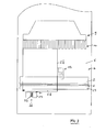
- FIG. 1 shown cutting machine 1 which is designed as a plan cutting machine, is used for cutting stacked, leaflet Good, especially those of paper, cardboard, films or the like, which is in cuboid shape.
- the cutting machine has a stand 2 with upper portal frame 3, further a table 4.
- the table 4 is provided with an upper, horizontal table surface, which serves to accommodate the stack, be it stack to be cut Guts or stack cut Guts, the latter as Benefit pile called.
- the table surface 5 thus extends perpendicular to the plane of the drawing sheet.
- a lowering and liftable cutting blade 6 is mounted, behind which a pressing beam 7 is also raised and lowered in the portal frame 3.
- the press beam 7 serves to fix the material to be cut by the pressing bar 7 presses the cut material stack against the table 4 in the lowered position.
- the cutting blade 6 is in the swing section by means of a crank mechanism from the in FIG. 1 illustrated upper end position movable in a lower end position in which it penetrates into a recorded by the table 4 cutting bar.
- the pressing beam 7 is by means of a drive from the in FIG. 1 illustrated raised position in the lowered, resting on the stack position lowered. In the raised position of the knife 6 and the pressing bar 7, the pressing bar 7 extends slightly below the level of the knife 6, so that the knife edge is not exposed.
- the drive motor for the cutting blade 6 is arranged in the right area of the portal frame 3 and accessible through an opening 8 in the portal frame 3 closing flap.
- a feed device In the area of the rear table part, a feed device is provided, which has a feed saddle 9 with front calculating section 10 which is designed in a known manner and which serves to advance the stack to be cut in the direction of the operator, perpendicular to the cutting plane.
- the side of the feed saddle 9 facing the operator runs parallel to the cutting plane of the cutting blade 6.
- the feed saddle 10 can be moved back and forth in the region of the rear part of the table.
- this is provided with a control and information display 11, which is a Touchscreen acts.
- the cutting machine 1 is actuated by two-handed operation by two control buttons 12 are provided in the front region of the table 4, at a distance from each other.
- the cutting machine is further provided in the region of both sides with side stops 13 for positioning the material to be cut to one or the other stop.
- an opening 14 is formed in the portal frame 3 between these and the table surface 5.
- the maximum dimension of the material to be cut in width and height is limited by this opening 14.
- arrangements 15, which, at the same starting position, are arranged symmetrically to a central plane 16, which is arranged perpendicular to the cutting plane, thus perpendicular to the drawing sheet.
- the respective arrangement 15 is essentially formed by a light barrier housing 17, photoelectric sensors 18 accommodated by the latter and a cover element 19.
- the light barriers 18 of the two arrangements 15 serve to protect the space in front of the cutting blade and the respective cover element 19 can be pivoted from the position illustrated in the figure into an end position with respect to the associated light barrier housing 17 in which the light beams or light signals of the light barriers 18 are interrupted. This is particularly important for the arrangement 15 illustrated on the right, if the flap 8 of the portal frame 3 is opened after pivoting the cover 19 into the light beams of the light barriers and maintenance work on the cutting machine 1, in particular on the drive of the cutting blade 6 are made.
- an electrical machine control 20 for the functions of the planing machine. 1 arranged in the stand 2 of the plan cutting machine 1 arranged in the stand 2 of the plan cutting machine 1 .
- This machine control is illustrated by a dashed line area.
- the operating and information display 11 On the operator-facing side of the portal frame 3, not only the operating and information display 11 is arranged, but also an operating unit 21, which in particular has an on-off switch 22 for switching on and off the planing machine 1.
- the table 4 has, on its side facing the operator, in the middle of the table 4, a hand wheel 23, which allows a slow forward or backward movement of the feed saddle 9 by rotation via a rotary potentiometer, which cooperates with the electrical machine control 20 manually by means of the feed saddle 9, the material to be cut is to be positioned exactly with respect to the cutting plane of the cutting blade 6. Furthermore, the plan cutting machine 1 in the region of the front side of the stator 2 in the region of the lower end of a centrally arranged foot pedal 24.
- the operator of the cutting machine 1 can move the pressing bar 7 into a cutting position, in which the pressing bar is positioned at a short distance above the stack to be cut and thus precisely by manipulating cutting marks of the top sheet of the stack with respect to a Thomasandeutungsline the press bar 7 of the stack can be aligned by the operator.
- This handling of the stack is usually done by the operator grasps the stack with both hands or acts on the stack laterally on one or two alignment devices.
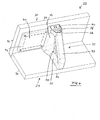
- FIG. 2 illustrates, greatly simplified, the cutting system 25 according to the invention, consisting of the previously described, in FIG. 2 only very simplified illustrated cutting machine 1 and a manually manageable alignment device 26 which is handled by the operator.
- This FIG. 2 It can be seen that the cutting blade 6 is held in a knife holder 27, which represents the actual storage of the cutting blade 6 in the portal frame 3.
- the cutting blade 6 is wedge-shaped, so that when cutting the illustrated entire stack 28 is separated a partial stack, which is parallellogrammförmig shifted.
- FIG. 2 illustrates the stack 28 in its advanced by means of the feed saddle 9 under the cutting blade 6 position when pressing the stack 28 through the pressing bar 7, before performing the cut.
- FIG. 4 A first embodiment of the alignment device 26 is shown in FIG FIG. 4 shown.
- the alignment device 26 has a first rectangular plate 29 with lower planar surface 30 and a perpendicular to this plate 29 arranged second, also cuboidal plate 31 which has a flat surface 32 on the side facing away from the plate 29, which is perpendicular to the surface 30 is.
- the surface 30 represents a contact surface, in the region of which the alignment device 26 can be placed on the table surface 5 of the table 4.
- the surface 32 of the alignment device 26 represents an alignment surface, in the region of which the material to be cut is contacted by means of the alignment device 26 for alignment.
- the two plates 29 and 31 have the same length and it is about half the length of the respective plate 29 and 31, a handle portion 33 connected to the two plates 29 and 31 having a handle recess 34.
- the handle portion 33 is formed as a triangular body having the handle recess 34, wherein the two legs 35, 36 of the handle portion 33, which enclose the right angle with each other, are connected to the plates 29 and 31.
- the two opposite ends of the two legs 35 and 36 connects a web 37 of the handle portion 33. In the region of this web 37, the alignment device 36 is gripped with one hand of the operator. In the transition from web 37 to leg 36, the associated ends of leg 36 and web 37 have control elements 38, 39 and 40.
- the control element 38 serves to operate the function of the feed forward feed, thus the movement of the feed saddle 9 forward in the direction of the cutting plane.
- the control element 39 is provided for the operation of the function of the saddle return.
- the operating element 40 can be used to change the speed of the feed forward feed and the feed saddle return. If the operating element 40 is transferred, for example, to a switching position which causes a fast feed saddle the subsequent pressing of the control element 38 to a fast saddle forward, the pressing of the control element 39 to a fast saddle return. If the control element 40 in the other switching position, the pressing of the control element 38 requires a slow Sattelvorlauf, pressing the control element 39 a slow saddle return.
- the operating elements 38, 39 and 40 interact electrically with further electrical components of the alignment device 26, specifically an electrical control which interacts with the electrical machine control 20 of the cutting machine 1.
- This electrical control in FIG. 4 is shown with a dashed line and designated by the reference numeral 41, is integrated into a handle portion 33 toward open cavity of the plate 31 and this cavity is closed by means of a cover 42.
- the alignment device 26 may be provided with an access barrier, in particular an electronic access barrier, wherein an activation of one, several or all electrical functions of the alignment device 26 can be blocked by means of the access barrier.
- the pressing bar 7 in its raised position with the control of the alignment device 26 activated, the operator can refrain from bringing about the exact movement of the feed saddle 9 by turning the hand wheel 23 of the cutting machine 1, but is able to do so by operating the operating elements 38 to 40 of the alignment 26 to accomplish.
- the operator can keep an eye on the stack and in this case operate the alignment device 26 such that a coarse, fast feed of the feed saddle 9 is first switched on by operation of the operating element 40 and then the fast feed movement is carried out by actuating the operating element 38. with on the table 4 resting alignment device 26, which may be handled by the operator, such as FIG. 2 and to FIG.
- FIG. 3 illustrates, with one hand, the alignment device 26 provided according to the invention, which has the electrical components move, and move with the other hand a conventional alignment device 26, which serves solely to align the goods, thus having no electrical components.
- the alignment device 26 provided according to the invention, which has the electrical components move, and move with the other hand a conventional alignment device 26, which serves solely to align the goods, thus having no electrical components.
- the dash-dotted line in FIG. 2 designated by the reference numeral 44, illustrates the cutting plane of the cutting blade 6, viewed perpendicular to the page plane of the drawing sheet.
- the uppermost sheet of the stack 28 is provided on its front, left side with a printed bar code 45, which can be evaluated by means of a bar code scanner of the alignment device 26.
- Data evaluated by the scanner can either be displayed on a display of the alignment device 26 or the operator and information display 11 of the slicer 1, or even processed by the machine controller in the sense of an automated processing operation of the stack 28.
- FIGS. 6 and 7 illustrate a second embodiment of the alignment device 26. This is with respect to the plates 29, 31 and the handle portion 33 substantially according to the embodiment according to FIG. 4 educated.
- the alignment device 26 according to the FIGS. 6 and 7 shows on the one side of the alignment 26, in addition to the handle portion 23, a box 46 in which not only the electronic control 41 of the alignment unit 26 is housed, but a bar code scanner whose scanner beam can pass through a rectangular passage opening 47 in the plate 29.
- a connection 48 with three sockets 49 for inserting mobile data memories is provided with the plate 29. For example, measured data or software updates relating to the alignment device having the electrical components are stored on these data memories.
- two controls 38 and 39 are arranged for flow and return of the feed saddle 9, further between these two controls 38, 39, a thumbwheel 50, said dial is connected to electrical components of the electrical control 41, such that more or less large Rotation angle of the adjusting wheel 50, the travel speed of the feed saddle 9, taking into account the operation by the controls 38 and 39 can be changed.
- the third embodiment according to the FIGS. 8 and 9 differs from the basic structure of the alignment device 26 according to the FIGS. 6 and 7 concerning plate 29, plate 31, handle 33 with handle recess 34 and the controls 38, 39 and the thumbwheel 50 characterized in that the plate 29 on one side of the handle portion 33, on the top of the plate 29, a touch screen 51 having with is connected to the electrical controller 51 and over the manually data can be entered and data can be displayed on this.
- this alignment device 26 on the other side of the handle portion 33, on the underside of the plate 29, measuring means 52 for measuring a travel path of the resting on the table 4 alignment device 26 relative to the table 4.
- These measuring means may comprise a wheel which is on the table 4 expires and the rotational movement is a reference for the distance covered by the alignment device 26.
- the alignment device 26 has a measuring means 53 for determining a force acting on this measuring means. When the alignment device 26 with the plate 31 is applied to the stack 28, it acts on the measuring means 53 projecting slightly beyond the surface 32 so that it can absorb the force with which the stack presses against the measuring means 53.
- the cutting system 25 described permits a wide variety of modifications, in particular with regard to the alignment device 26 and the control of the cutting machine 1 by means of the alignment device 26 or the activation of the alignment device 26 by means of the cutting machine 1.
- the alignment device 26 may also have operating elements that cause the function of the foot pedal 26 to perform the Thomasandeutung by lowering the press bar 7 in a position slightly above the stack to be cut 28. It is therefore not necessary for the operator to operate the foot pedal 24. Thus, without letting the area of interest of the stack 28 out of sight, by actuating one or more operating elements of the alignment device 26, this function can be achieved.
- the function of the pressure change of the press bar can also be integrated into the alignment device 26.
Landscapes
- Life Sciences & Earth Sciences (AREA)
- Forests & Forestry (AREA)
- Engineering & Computer Science (AREA)
- Mechanical Engineering (AREA)
- Details Of Cutting Devices (AREA)
- Control Of Cutting Processes (AREA)
Priority Applications (3)
| Application Number | Priority Date | Filing Date | Title |
|---|---|---|---|
| EP20120166048 EP2656984B1 (fr) | 2012-04-27 | 2012-04-27 | Système de coupe avec machine à découper et un dispositif d'alignement |
| US14/396,122 US10052778B2 (en) | 2012-04-27 | 2013-04-19 | Cutting system with cutting machine and an alignment device |
| PCT/EP2013/001162 WO2013159885A1 (fr) | 2012-04-27 | 2013-04-19 | Système de coupe comprenant une machine de coupe et un dispositif d'orientation |
Applications Claiming Priority (1)
| Application Number | Priority Date | Filing Date | Title |
|---|---|---|---|
| EP20120166048 EP2656984B1 (fr) | 2012-04-27 | 2012-04-27 | Système de coupe avec machine à découper et un dispositif d'alignement |
Publications (2)
| Publication Number | Publication Date |
|---|---|
| EP2656984A1 true EP2656984A1 (fr) | 2013-10-30 |
| EP2656984B1 EP2656984B1 (fr) | 2015-02-25 |
Family
ID=48520878
Family Applications (1)
| Application Number | Title | Priority Date | Filing Date |
|---|---|---|---|
| EP20120166048 Active EP2656984B1 (fr) | 2012-04-27 | 2012-04-27 | Système de coupe avec machine à découper et un dispositif d'alignement |
Country Status (3)
| Country | Link |
|---|---|
| US (1) | US10052778B2 (fr) |
| EP (1) | EP2656984B1 (fr) |
| WO (1) | WO2013159885A1 (fr) |
Cited By (1)
| Publication number | Priority date | Publication date | Assignee | Title |
|---|---|---|---|---|
| EP4302947A1 (fr) * | 2022-07-07 | 2024-01-10 | Adolf Mohr Maschinenfabrik GmbH & Co. KG | Machine de coupe |
Families Citing this family (6)
| Publication number | Priority date | Publication date | Assignee | Title |
|---|---|---|---|---|
| JP7030601B2 (ja) * | 2018-04-05 | 2022-03-07 | 極東産機株式会社 | 畳床の裁断装置 |
| WO2020017684A1 (fr) * | 2018-07-16 | 2020-01-23 | (주)파인테크 | Appareil et procédé de poinçonnage d'un film |
| WO2021251072A1 (fr) * | 2020-06-08 | 2021-12-16 | 住友電気工業株式会社 | Outil de coupe, système d'outil et procédé de commande de communication |
| EP4056336A1 (fr) | 2021-03-12 | 2022-09-14 | Adolf Mohr Maschinenfabrik GmbH & Co. KG | Machine de coupe permettant de couper des marchandises empilées en forme de feuilles dotée d'un dispositif de correction de l'alignement des marchandises à couper |
| KR102867052B1 (ko) * | 2022-12-15 | 2025-10-13 | 주식회사 이츠유컴퍼니 | 커팅용 조깅블록 |
| EP4414146A1 (fr) | 2023-02-13 | 2024-08-14 | POLAR-Mohr Beteiligungs GmbH | Procédé de correction d'une orientation d'une position de coupe et machine de coupe |
Citations (4)
| Publication number | Priority date | Publication date | Assignee | Title |
|---|---|---|---|---|
| DE3101911A1 (de) | 1981-01-22 | 1982-09-02 | Karl Mohr | "vorrichtung zum schneiden von papier, pappe oder dgl.." |
| EP0829332A1 (fr) * | 1996-09-12 | 1998-03-18 | Adolf Mohr Maschinenfabrik GmbH & Co. KG | Dispositif pour la coupe de matériau en feuille |
| EP0972618A2 (fr) * | 1998-07-16 | 2000-01-19 | Adolf Mohr Maschinenfabrik GmbH & Co. KG | Machine de coupe pour matériaux en feuilles empilées |
| EP1018408A1 (fr) | 1998-12-28 | 2000-07-12 | Adolf Mohr Maschinenfabrik GmbH & Co. KG | Guillotine pour couper des produits en feuilles empilées |
Family Cites Families (11)
| Publication number | Priority date | Publication date | Assignee | Title |
|---|---|---|---|---|
| US5251142A (en) * | 1990-12-14 | 1993-10-05 | Digital Cutting Systems, Inc. | Rip fence of table saw which may be positioned by computer control |
| CN1198700C (zh) * | 1998-11-12 | 2005-04-27 | 布莱克和戴克公司 | 斜切锯操作台 |
| DE59807671D1 (de) * | 1998-12-28 | 2003-04-30 | Mohr Adolf Maschf | Verfahren zur Bildung und Weiterverarbeitung von kleinen Blattgutstapeln |
| US6327949B1 (en) * | 1999-12-07 | 2001-12-11 | Larry J. Abernathy | Motorized saw hand guard |
| US20060076385A1 (en) * | 2002-04-18 | 2006-04-13 | Etter Mark A | Power tool control system |
| US7574949B2 (en) * | 2003-07-31 | 2009-08-18 | Hadaway Jeffrey P | Computer numerically controlled table saw fence |
| US7401416B2 (en) * | 2006-09-05 | 2008-07-22 | Brooks Mark B | System for measuring and cutting |
| TW200821116A (en) * | 2006-11-09 | 2008-05-16 | Rexon Ind Corp Ltd | Table saw machine |
| US8453549B2 (en) * | 2008-01-15 | 2013-06-04 | Technical Services, Inc. | Method and apparatus for sawing lineal material to length |
| JP5142271B2 (ja) * | 2008-05-23 | 2013-02-13 | ホリゾン・インターナショナル株式会社 | 用紙断裁機における断裁順表示装置 |
| US9808949B2 (en) * | 2012-05-29 | 2017-11-07 | Horizon International Inc. | Trimmer |
-
2012
- 2012-04-27 EP EP20120166048 patent/EP2656984B1/fr active Active
-
2013
- 2013-04-19 WO PCT/EP2013/001162 patent/WO2013159885A1/fr not_active Ceased
- 2013-04-19 US US14/396,122 patent/US10052778B2/en active Active
Patent Citations (4)
| Publication number | Priority date | Publication date | Assignee | Title |
|---|---|---|---|---|
| DE3101911A1 (de) | 1981-01-22 | 1982-09-02 | Karl Mohr | "vorrichtung zum schneiden von papier, pappe oder dgl.." |
| EP0829332A1 (fr) * | 1996-09-12 | 1998-03-18 | Adolf Mohr Maschinenfabrik GmbH & Co. KG | Dispositif pour la coupe de matériau en feuille |
| EP0972618A2 (fr) * | 1998-07-16 | 2000-01-19 | Adolf Mohr Maschinenfabrik GmbH & Co. KG | Machine de coupe pour matériaux en feuilles empilées |
| EP1018408A1 (fr) | 1998-12-28 | 2000-07-12 | Adolf Mohr Maschinenfabrik GmbH & Co. KG | Guillotine pour couper des produits en feuilles empilées |
Cited By (2)
| Publication number | Priority date | Publication date | Assignee | Title |
|---|---|---|---|---|
| EP4302947A1 (fr) * | 2022-07-07 | 2024-01-10 | Adolf Mohr Maschinenfabrik GmbH & Co. KG | Machine de coupe |
| WO2024008689A1 (fr) * | 2022-07-07 | 2024-01-11 | Polar-Mohr Beteiligungs Gmbh | Machine de coupe |
Also Published As
| Publication number | Publication date |
|---|---|
| WO2013159885A1 (fr) | 2013-10-31 |
| US20150122098A1 (en) | 2015-05-07 |
| EP2656984B1 (fr) | 2015-02-25 |
| US10052778B2 (en) | 2018-08-21 |
Similar Documents
| Publication | Publication Date | Title |
|---|---|---|
| EP2656984B1 (fr) | Système de coupe avec machine à découper et un dispositif d'alignement | |
| EP0242763B1 (fr) | Dispositif pour couper des feuilles empilées | |
| DE3107436C2 (fr) | ||
| DE60015488T2 (de) | Automatische Hobelmaschine zum Bearbeiten von Flitchen | |
| DE4228651A1 (de) | Verfahren und Vorrichtung zum Optimieren des Schneidevorganges bei einer Schneidemaschine | |
| DE3035962C3 (de) | Vorrichtung zum Steuern der Antriebe einer Bandsägemaschine | |
| EP1018408B1 (fr) | Guillotine pour couper des produits en feuilles empilées | |
| EP3246690A1 (fr) | Microtome avec joystick | |
| DE3613315A1 (de) | Anordnung zum zufuehren von gestapeltem, blattfoermigen gut zu einer weiterverarbeitungsstation, insbesondere schneidstation | |
| EP0406219B1 (fr) | Dispositif pour découper des pièces, en particulier des pièces en bois | |
| WO2009138366A1 (fr) | Trancheuse pour produits alimentaires | |
| EP1000715B1 (fr) | Dispositif pour la coupe de matériaux en feuilles empilées | |
| EP2123412B1 (fr) | Machine de coupe destinée à la coupe de articles empilés, en forme de feuilles, et procédé | |
| DE3245925C2 (de) | Gerät zum Schneiden von Blöcken und Anwendung desselben | |
| EP2591897B1 (fr) | Machine de découpage pour découper des produits empilés en forme de feuilles à l'aide d'une barrière lumineuse | |
| DE2654000B2 (de) | Maschine zum Ausbrechen von Nutzen | |
| EP2656985A1 (fr) | Machine à découper pour la découpe de produits empilés en forme de feuilles | |
| EP2058256B1 (fr) | Dispositif destiné à secouer un bien en forme de feuilles empilées | |
| EP2228182B1 (fr) | Procédé de production de piles utiles à l'aide d'une machine de découpage de plans | |
| EP0829332B1 (fr) | Dispositif pour la coupe de matériau en feuille | |
| DE2429903A1 (de) | Vorrichtung zum loesen von ausgestanztem stanzgut aus einem stapel bzw. zum abtrennen von stanzgut und abfall | |
| DE4002101A1 (de) | Vorrichtung zum schneiden von gestapeltem, blattfoermigem gut mit seitenanschlag und gegen diesen bewegbarem andruckschieber zum ausrichten des zu schneidenden gutes | |
| DE1258583B (de) | Durchlaufschere zum Ausschneiden fehlerhafter oder ungleichmaessiger Stellen einer Werkstoffbahn, insbesondere Furnierbahn | |
| DE1561544C3 (de) | Vorrichtung zum Ausschneiden der Bildfenster von Passepartouts | |
| DE6911788U (de) | Hoehenverstellbare schutzvorrichtung fuer bandmesserzuschneidemaschinen fuer stoffe oder aehnliche maschinen |
Legal Events
| Date | Code | Title | Description |
|---|---|---|---|
| PUAI | Public reference made under article 153(3) epc to a published international application that has entered the european phase |
Free format text: ORIGINAL CODE: 0009012 |
|
| AK | Designated contracting states |
Kind code of ref document: A1 Designated state(s): AL AT BE BG CH CY CZ DE DK EE ES FI FR GB GR HR HU IE IS IT LI LT LU LV MC MK MT NL NO PL PT RO RS SE SI SK SM TR |
|
| AX | Request for extension of the european patent |
Extension state: BA ME |
|
| 17P | Request for examination filed |
Effective date: 20140408 |
|
| RBV | Designated contracting states (corrected) |
Designated state(s): AL AT BE BG CH CY CZ DE DK EE ES FI FR GB GR HR HU IE IS IT LI LT LU LV MC MK MT NL NO PL PT RO RS SE SI SK SM TR |
|
| GRAP | Despatch of communication of intention to grant a patent |
Free format text: ORIGINAL CODE: EPIDOSNIGR1 |
|
| RIC1 | Information provided on ipc code assigned before grant |
Ipc: B26D 5/00 20060101AFI20140917BHEP Ipc: B26D 7/01 20060101ALI20140917BHEP |
|
| INTG | Intention to grant announced |
Effective date: 20141013 |
|
| GRAS | Grant fee paid |
Free format text: ORIGINAL CODE: EPIDOSNIGR3 |
|
| GRAA | (expected) grant |
Free format text: ORIGINAL CODE: 0009210 |
|
| AK | Designated contracting states |
Kind code of ref document: B1 Designated state(s): AL AT BE BG CH CY CZ DE DK EE ES FI FR GB GR HR HU IE IS IT LI LT LU LV MC MK MT NL NO PL PT RO RS SE SI SK SM TR |
|
| REG | Reference to a national code |
Ref country code: GB Ref legal event code: FG4D Free format text: NOT ENGLISH |
|
| REG | Reference to a national code |
Ref country code: CH Ref legal event code: EP |
|
| REG | Reference to a national code |
Ref country code: IE Ref legal event code: FG4D Free format text: LANGUAGE OF EP DOCUMENT: GERMAN |
|
| REG | Reference to a national code |
Ref country code: DE Ref legal event code: R096 Ref document number: 502012002320 Country of ref document: DE Effective date: 20150402 |
|
| REG | Reference to a national code |
Ref country code: AT Ref legal event code: REF Ref document number: 711532 Country of ref document: AT Kind code of ref document: T Effective date: 20150415 |
|
| REG | Reference to a national code |
Ref country code: NL Ref legal event code: VDEP Effective date: 20150225 |
|
| REG | Reference to a national code |
Ref country code: LT Ref legal event code: MG4D |
|
| PG25 | Lapsed in a contracting state [announced via postgrant information from national office to epo] |
Ref country code: ES Free format text: LAPSE BECAUSE OF FAILURE TO SUBMIT A TRANSLATION OF THE DESCRIPTION OR TO PAY THE FEE WITHIN THE PRESCRIBED TIME-LIMIT Effective date: 20150225 Ref country code: SE Free format text: LAPSE BECAUSE OF FAILURE TO SUBMIT A TRANSLATION OF THE DESCRIPTION OR TO PAY THE FEE WITHIN THE PRESCRIBED TIME-LIMIT Effective date: 20150225 Ref country code: HR Free format text: LAPSE BECAUSE OF FAILURE TO SUBMIT A TRANSLATION OF THE DESCRIPTION OR TO PAY THE FEE WITHIN THE PRESCRIBED TIME-LIMIT Effective date: 20150225 Ref country code: NO Free format text: LAPSE BECAUSE OF FAILURE TO SUBMIT A TRANSLATION OF THE DESCRIPTION OR TO PAY THE FEE WITHIN THE PRESCRIBED TIME-LIMIT Effective date: 20150525 Ref country code: LT Free format text: LAPSE BECAUSE OF FAILURE TO SUBMIT A TRANSLATION OF THE DESCRIPTION OR TO PAY THE FEE WITHIN THE PRESCRIBED TIME-LIMIT Effective date: 20150225 Ref country code: FI Free format text: LAPSE BECAUSE OF FAILURE TO SUBMIT A TRANSLATION OF THE DESCRIPTION OR TO PAY THE FEE WITHIN THE PRESCRIBED TIME-LIMIT Effective date: 20150225 |
|
| PG25 | Lapsed in a contracting state [announced via postgrant information from national office to epo] |
Ref country code: GR Free format text: LAPSE BECAUSE OF FAILURE TO SUBMIT A TRANSLATION OF THE DESCRIPTION OR TO PAY THE FEE WITHIN THE PRESCRIBED TIME-LIMIT Effective date: 20150526 Ref country code: LV Free format text: LAPSE BECAUSE OF FAILURE TO SUBMIT A TRANSLATION OF THE DESCRIPTION OR TO PAY THE FEE WITHIN THE PRESCRIBED TIME-LIMIT Effective date: 20150225 Ref country code: RS Free format text: LAPSE BECAUSE OF FAILURE TO SUBMIT A TRANSLATION OF THE DESCRIPTION OR TO PAY THE FEE WITHIN THE PRESCRIBED TIME-LIMIT Effective date: 20150225 Ref country code: IS Free format text: LAPSE BECAUSE OF FAILURE TO SUBMIT A TRANSLATION OF THE DESCRIPTION OR TO PAY THE FEE WITHIN THE PRESCRIBED TIME-LIMIT Effective date: 20150625 |
|
| PG25 | Lapsed in a contracting state [announced via postgrant information from national office to epo] |
Ref country code: NL Free format text: LAPSE BECAUSE OF FAILURE TO SUBMIT A TRANSLATION OF THE DESCRIPTION OR TO PAY THE FEE WITHIN THE PRESCRIBED TIME-LIMIT Effective date: 20150225 |
|
| PG25 | Lapsed in a contracting state [announced via postgrant information from national office to epo] |
Ref country code: SK Free format text: LAPSE BECAUSE OF FAILURE TO SUBMIT A TRANSLATION OF THE DESCRIPTION OR TO PAY THE FEE WITHIN THE PRESCRIBED TIME-LIMIT Effective date: 20150225 Ref country code: CZ Free format text: LAPSE BECAUSE OF FAILURE TO SUBMIT A TRANSLATION OF THE DESCRIPTION OR TO PAY THE FEE WITHIN THE PRESCRIBED TIME-LIMIT Effective date: 20150225 Ref country code: EE Free format text: LAPSE BECAUSE OF FAILURE TO SUBMIT A TRANSLATION OF THE DESCRIPTION OR TO PAY THE FEE WITHIN THE PRESCRIBED TIME-LIMIT Effective date: 20150225 Ref country code: DK Free format text: LAPSE BECAUSE OF FAILURE TO SUBMIT A TRANSLATION OF THE DESCRIPTION OR TO PAY THE FEE WITHIN THE PRESCRIBED TIME-LIMIT Effective date: 20150225 Ref country code: RO Free format text: LAPSE BECAUSE OF FAILURE TO SUBMIT A TRANSLATION OF THE DESCRIPTION OR TO PAY THE FEE WITHIN THE PRESCRIBED TIME-LIMIT Effective date: 20150225 |
|
| REG | Reference to a national code |
Ref country code: DE Ref legal event code: R097 Ref document number: 502012002320 Country of ref document: DE |
|
| PG25 | Lapsed in a contracting state [announced via postgrant information from national office to epo] |
Ref country code: PL Free format text: LAPSE BECAUSE OF FAILURE TO SUBMIT A TRANSLATION OF THE DESCRIPTION OR TO PAY THE FEE WITHIN THE PRESCRIBED TIME-LIMIT Effective date: 20150225 Ref country code: MC Free format text: LAPSE BECAUSE OF FAILURE TO SUBMIT A TRANSLATION OF THE DESCRIPTION OR TO PAY THE FEE WITHIN THE PRESCRIBED TIME-LIMIT Effective date: 20150225 Ref country code: LU Free format text: LAPSE BECAUSE OF FAILURE TO SUBMIT A TRANSLATION OF THE DESCRIPTION OR TO PAY THE FEE WITHIN THE PRESCRIBED TIME-LIMIT Effective date: 20150427 |
|
| REG | Reference to a national code |
Ref country code: CH Ref legal event code: PL |
|
| PG25 | Lapsed in a contracting state [announced via postgrant information from national office to epo] |
Ref country code: IT Free format text: LAPSE BECAUSE OF FAILURE TO SUBMIT A TRANSLATION OF THE DESCRIPTION OR TO PAY THE FEE WITHIN THE PRESCRIBED TIME-LIMIT Effective date: 20150225 |
|
| PLBE | No opposition filed within time limit |
Free format text: ORIGINAL CODE: 0009261 |
|
| STAA | Information on the status of an ep patent application or granted ep patent |
Free format text: STATUS: NO OPPOSITION FILED WITHIN TIME LIMIT |
|
| REG | Reference to a national code |
Ref country code: IE Ref legal event code: MM4A |
|
| PG25 | Lapsed in a contracting state [announced via postgrant information from national office to epo] |
Ref country code: LI Free format text: LAPSE BECAUSE OF NON-PAYMENT OF DUE FEES Effective date: 20150430 Ref country code: CH Free format text: LAPSE BECAUSE OF NON-PAYMENT OF DUE FEES Effective date: 20150430 |
|
| REG | Reference to a national code |
Ref country code: FR Ref legal event code: ST Effective date: 20151231 |
|
| 26N | No opposition filed |
Effective date: 20151126 |
|
| PG25 | Lapsed in a contracting state [announced via postgrant information from national office to epo] |
Ref country code: SI Free format text: LAPSE BECAUSE OF FAILURE TO SUBMIT A TRANSLATION OF THE DESCRIPTION OR TO PAY THE FEE WITHIN THE PRESCRIBED TIME-LIMIT Effective date: 20150225 Ref country code: FR Free format text: LAPSE BECAUSE OF NON-PAYMENT OF DUE FEES Effective date: 20150430 |
|
| PG25 | Lapsed in a contracting state [announced via postgrant information from national office to epo] |
Ref country code: IE Free format text: LAPSE BECAUSE OF NON-PAYMENT OF DUE FEES Effective date: 20150427 |
|
| GBPC | Gb: european patent ceased through non-payment of renewal fee |
Effective date: 20160427 |
|
| PG25 | Lapsed in a contracting state [announced via postgrant information from national office to epo] |
Ref country code: MT Free format text: LAPSE BECAUSE OF FAILURE TO SUBMIT A TRANSLATION OF THE DESCRIPTION OR TO PAY THE FEE WITHIN THE PRESCRIBED TIME-LIMIT Effective date: 20150225 |
|
| PG25 | Lapsed in a contracting state [announced via postgrant information from national office to epo] |
Ref country code: GB Free format text: LAPSE BECAUSE OF NON-PAYMENT OF DUE FEES Effective date: 20160427 |
|
| PG25 | Lapsed in a contracting state [announced via postgrant information from national office to epo] |
Ref country code: BG Free format text: LAPSE BECAUSE OF FAILURE TO SUBMIT A TRANSLATION OF THE DESCRIPTION OR TO PAY THE FEE WITHIN THE PRESCRIBED TIME-LIMIT Effective date: 20150225 Ref country code: HU Free format text: LAPSE BECAUSE OF FAILURE TO SUBMIT A TRANSLATION OF THE DESCRIPTION OR TO PAY THE FEE WITHIN THE PRESCRIBED TIME-LIMIT; INVALID AB INITIO Effective date: 20120427 Ref country code: SM Free format text: LAPSE BECAUSE OF FAILURE TO SUBMIT A TRANSLATION OF THE DESCRIPTION OR TO PAY THE FEE WITHIN THE PRESCRIBED TIME-LIMIT Effective date: 20150225 |
|
| PG25 | Lapsed in a contracting state [announced via postgrant information from national office to epo] |
Ref country code: CY Free format text: LAPSE BECAUSE OF FAILURE TO SUBMIT A TRANSLATION OF THE DESCRIPTION OR TO PAY THE FEE WITHIN THE PRESCRIBED TIME-LIMIT Effective date: 20150225 |
|
| PG25 | Lapsed in a contracting state [announced via postgrant information from national office to epo] |
Ref country code: BE Free format text: LAPSE BECAUSE OF NON-PAYMENT OF DUE FEES Effective date: 20150430 Ref country code: PT Free format text: LAPSE BECAUSE OF FAILURE TO SUBMIT A TRANSLATION OF THE DESCRIPTION OR TO PAY THE FEE WITHIN THE PRESCRIBED TIME-LIMIT Effective date: 20150625 |
|
| PG25 | Lapsed in a contracting state [announced via postgrant information from national office to epo] |
Ref country code: TR Free format text: LAPSE BECAUSE OF FAILURE TO SUBMIT A TRANSLATION OF THE DESCRIPTION OR TO PAY THE FEE WITHIN THE PRESCRIBED TIME-LIMIT Effective date: 20150225 |
|
| REG | Reference to a national code |
Ref country code: AT Ref legal event code: MM01 Ref document number: 711532 Country of ref document: AT Kind code of ref document: T Effective date: 20170427 |
|
| PG25 | Lapsed in a contracting state [announced via postgrant information from national office to epo] |
Ref country code: MK Free format text: LAPSE BECAUSE OF FAILURE TO SUBMIT A TRANSLATION OF THE DESCRIPTION OR TO PAY THE FEE WITHIN THE PRESCRIBED TIME-LIMIT Effective date: 20150225 |
|
| PG25 | Lapsed in a contracting state [announced via postgrant information from national office to epo] |
Ref country code: AT Free format text: LAPSE BECAUSE OF NON-PAYMENT OF DUE FEES Effective date: 20170427 |
|
| PG25 | Lapsed in a contracting state [announced via postgrant information from national office to epo] |
Ref country code: AL Free format text: LAPSE BECAUSE OF FAILURE TO SUBMIT A TRANSLATION OF THE DESCRIPTION OR TO PAY THE FEE WITHIN THE PRESCRIBED TIME-LIMIT Effective date: 20150225 |
|
| REG | Reference to a national code |
Ref country code: DE Ref legal event code: R081 Ref document number: 502012002320 Country of ref document: DE Owner name: POLAR-MOHR BETEILIGUNGS GMBH, DE Free format text: FORMER OWNER: ADOLF MOHR MASCHINENFABRIK GMBH & CO. KG, 65719 HOFHEIM, DE Ref country code: DE Ref legal event code: R081 Ref document number: 502012002320 Country of ref document: DE Owner name: HEIDELBERGER DRUCKMASCHINEN AKTIENGESELLSCHAFT, DE Free format text: FORMER OWNER: ADOLF MOHR MASCHINENFABRIK GMBH & CO. KG, 65719 HOFHEIM, DE |
|
| P01 | Opt-out of the competence of the unified patent court (upc) registered |
Effective date: 20230524 |
|
| PGFP | Annual fee paid to national office [announced via postgrant information from national office to epo] |
Ref country code: DE Payment date: 20250425 Year of fee payment: 14 |
|
| REG | Reference to a national code |
Ref country code: DE Ref legal event code: R081 Ref document number: 502012002320 Country of ref document: DE Owner name: HEIDELBERGER DRUCKMASCHINEN AKTIENGESELLSCHAFT, DE Free format text: FORMER OWNER: POLAR-MOHR BETEILIGUNGS GMBH, 65719 HOFHEIM, DE Ref country code: DE Ref legal event code: R082 Ref document number: 502012002320 Country of ref document: DE |