EP2657032B1 - Dispositif et système de remplissage de cartouche d'encre et procédé associé - Google Patents
Dispositif et système de remplissage de cartouche d'encre et procédé associé Download PDFInfo
- Publication number
- EP2657032B1 EP2657032B1 EP11851601.2A EP11851601A EP2657032B1 EP 2657032 B1 EP2657032 B1 EP 2657032B1 EP 11851601 A EP11851601 A EP 11851601A EP 2657032 B1 EP2657032 B1 EP 2657032B1
- Authority
- EP
- European Patent Office
- Prior art keywords
- ink cartridge
- ink
- refilling
- sealing
- air inlet
- Prior art date
- Legal status (The legal status is an assumption and is not a legal conclusion. Google has not performed a legal analysis and makes no representation as to the accuracy of the status listed.)
- Not-in-force
Links
- 238000000034 method Methods 0.000 title claims description 19
- 238000007789 sealing Methods 0.000 claims description 91
- 238000002347 injection Methods 0.000 claims description 37
- 239000007924 injection Substances 0.000 claims description 37
- 230000007246 mechanism Effects 0.000 claims description 37
- 230000009471 action Effects 0.000 claims description 11
- 238000003860 storage Methods 0.000 description 17
- 238000010586 diagram Methods 0.000 description 13
- 229920000742 Cotton Polymers 0.000 description 7
- 229910000831 Steel Inorganic materials 0.000 description 5
- 230000008569 process Effects 0.000 description 5
- 239000010959 steel Substances 0.000 description 5
- VYPSYNLAJGMNEJ-UHFFFAOYSA-N Silicium dioxide Chemical compound O=[Si]=O VYPSYNLAJGMNEJ-UHFFFAOYSA-N 0.000 description 3
- 239000013013 elastic material Substances 0.000 description 3
- 238000007639 printing Methods 0.000 description 3
- 239000000741 silica gel Substances 0.000 description 3
- 229910002027 silica gel Inorganic materials 0.000 description 3
- 239000007788 liquid Substances 0.000 description 2
- 239000004033 plastic Substances 0.000 description 2
- 229920003023 plastic Polymers 0.000 description 2
- 238000000926 separation method Methods 0.000 description 2
- 239000012780 transparent material Substances 0.000 description 2
- 238000003466 welding Methods 0.000 description 2
- 239000004568 cement Substances 0.000 description 1
- 230000007547 defect Effects 0.000 description 1
- 238000009826 distribution Methods 0.000 description 1
- 238000005516 engineering process Methods 0.000 description 1
- 238000003912 environmental pollution Methods 0.000 description 1
- 239000012530 fluid Substances 0.000 description 1
- 238000001746 injection moulding Methods 0.000 description 1
- 238000004519 manufacturing process Methods 0.000 description 1
- 230000004048 modification Effects 0.000 description 1
- 238000012986 modification Methods 0.000 description 1
- 239000011148 porous material Substances 0.000 description 1
- 238000003825 pressing Methods 0.000 description 1
- 230000001360 synchronised effect Effects 0.000 description 1
- 239000002699 waste material Substances 0.000 description 1
Images


Classifications
-
- B—PERFORMING OPERATIONS; TRANSPORTING
- B41—PRINTING; LINING MACHINES; TYPEWRITERS; STAMPS
- B41J—TYPEWRITERS; SELECTIVE PRINTING MECHANISMS, i.e. MECHANISMS PRINTING OTHERWISE THAN FROM A FORME; CORRECTION OF TYPOGRAPHICAL ERRORS
- B41J2/00—Typewriters or selective printing mechanisms characterised by the printing or marking process for which they are designed
- B41J2/005—Typewriters or selective printing mechanisms characterised by the printing or marking process for which they are designed characterised by bringing liquid or particles selectively into contact with a printing material
- B41J2/01—Ink jet
- B41J2/17—Ink jet characterised by ink handling
- B41J2/175—Ink supply systems ; Circuit parts therefor
- B41J2/17503—Ink cartridges
- B41J2/17506—Refilling of the cartridge
-
- B—PERFORMING OPERATIONS; TRANSPORTING
- B41—PRINTING; LINING MACHINES; TYPEWRITERS; STAMPS
- B41J—TYPEWRITERS; SELECTIVE PRINTING MECHANISMS, i.e. MECHANISMS PRINTING OTHERWISE THAN FROM A FORME; CORRECTION OF TYPOGRAPHICAL ERRORS
- B41J2/00—Typewriters or selective printing mechanisms characterised by the printing or marking process for which they are designed
- B41J2/005—Typewriters or selective printing mechanisms characterised by the printing or marking process for which they are designed characterised by bringing liquid or particles selectively into contact with a printing material
- B41J2/01—Ink jet
- B41J2/17—Ink jet characterised by ink handling
- B41J2/175—Ink supply systems ; Circuit parts therefor
- B41J2/17503—Ink cartridges
- B41J2/17513—Inner structure
-
- B—PERFORMING OPERATIONS; TRANSPORTING
- B41—PRINTING; LINING MACHINES; TYPEWRITERS; STAMPS
- B41J—TYPEWRITERS; SELECTIVE PRINTING MECHANISMS, i.e. MECHANISMS PRINTING OTHERWISE THAN FROM A FORME; CORRECTION OF TYPOGRAPHICAL ERRORS
- B41J2/00—Typewriters or selective printing mechanisms characterised by the printing or marking process for which they are designed
- B41J2/005—Typewriters or selective printing mechanisms characterised by the printing or marking process for which they are designed characterised by bringing liquid or particles selectively into contact with a printing material
- B41J2/01—Ink jet
- B41J2/17—Ink jet characterised by ink handling
- B41J2/175—Ink supply systems ; Circuit parts therefor
- B41J2/17503—Ink cartridges
- B41J2/17553—Outer structure
Definitions
- Inkjet printhead is a necessary component of an inkjet printer, wherein the inkjet printhead is arranged on a carriage of the inkjet printer, which moves back and forth, and ejects ink to a recording medium along with the movement of the carriage, so as to form an image on the recording medium.
- Ink cartridge is used as an ink storage container and is responsible to supply ink to the printhead. As the ink level of the ink cartridge is limited, a user needs to replace the ink cartridge after the ink in the ink cartridge is out. However, most used ink cartridges are thrown away but cannot be degraded naturally as the ink cartridges contain plastic cements, chips and the like, which would obviously cause resource waste and environmental pollution and increase the printing cost of users.
- the most economical and environment-friendly mode is for the used ink cartridges to be refilled with ink so that the ink cartridges can be subjected to secondary utilization. Therefore, in order to meet the requirement, there are various ink cartridge refilling devices on the market.
- the Chinese patent CN200620061311 .X discloses a negative-pressure ink cartridge refilling device.
- the refilling device comprises an air suction mechanism and an ink injection mechanism, wherein the air suction mechanism consists of a cylinder and a piston; the cylinder consists of a sealed cavity and a connecting opening which connects the outside and the mentioned sealed cavity; the piston is pneumatically sealed inside the sealed cavity; the ink injection mechanism consists of an ink storage cavity and an ink injection opening which communicates the outside and the ink storage cavity; and the ink storage cavity is communicated with a section of the sealed cavity of the cylinder, which is positioned at the outside of the piston compared with the connecting opening, through a guide tube.
- the mode for utilizing the above mentioned negative-pressure ink cartridge refilling device for ink refilling is as follows: sucking ink into the ink storage cavity of the ink cartridge refilling device in advance, and aligning the connecting opening and the ink injection opening to an air suction hole and an ink injection hole of an ink cartridge respectively, so that the synchronized operation of two steps can be realized, namely air in the ink cartridge is sucked and removed on one hand while ink is refilled into the ink cartridge simultaneously on the other hand.
- the above refilling method is comparatively convenient.
- the refilling method has the defect that: as a sponge of a cavernous cavity tends to be in a supersaturated state after the ink refilling, the ink dropping phenomenon tends to occur if the ink cartridge after the ink refilling is directly taken off, thus the environment is polluted or hands, clothes, etc. of users are dirtied.
- CN201645992U discloses the preamble of claim 1.
- the invention provides an ink cartridge refilling device to solve the technical problem in the traditional ink cartridge refilling device that the ink dropping phenomenon tends to occur after an ink cartridge is filled with ink.
- the invention adopts the technical proposal according to claims 1 to 22.
- the cover component is provided with the first sealing section for sealing the ink cartridge to be refilled and the second sealing section for sealing the air inlet channel
- air in a sealed ink cartridge can be sucked to enable ink in the ink container to flow into the sealed ink cartridge during the ink refilling, thus negative pressure is formed in the ink container and the ink is conveyed from the ink container to the ink cartridge under the negative pressure, consequently the refilling of the ink into the ink cartridge and the replenishing of the air into the ink container may not be carried out at the same time.
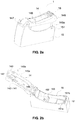
- the negative-pressure cavity 21 is provided with an adsorbing member for holding the ink, and the adsorbing member is mostly made of porous materials and is preferably a sponge 211 in the embodiment, namely the sponge 211 can adsorb and hold the ink by utilization of the capillary force of the sponge 211, thus the negative pressure in the ink cartridge 2 can be controlled.
- an ink outlet 22 for introducing the ink in the ink cartridge 2 to the printhead for the printer is also arranged at the bottom of the negative-pressure cavity 21, and an air inlet 23 for replenishing outside air into the ink cartridge 2 is also arranged at the top wall of the negative-pressure cavity 21.
- the ink outlet 22 is also provided with a cotton core 221 of which the density is higher than that of the sponge 211 in the negative-pressure cavity 21, and the cotton core 221 is in contact with an ink supply end on the printer to introduce ink to flow to the ink outlet 22 and be supplied to the printhead through the ink supply end when the ink cartridge 2 is installed on the printer.
- the ink cartridge 2 is also provided with an ink injection opening 24 which is used for injecting ink into the ink cartridge 2.
- the ink injection opening 24 is arranged on the ink storage cavity 20 and sealed by a steel ball after the ink refilling for the first time, so that the leakage phenomenon of the ink cartridge 2 when transported or used can be prevented.
- a prism 27 for detecting the ink-out state of the ink cartridge 2 is also arranged at the bottom wall of the ink storage cavity 20.
- the process of detecting the ink level by adoption of the prism 27 belongs to the mature technology of the field and is not explained in detail here.
- a movable member 25 provided with a first engagement section 251 and a second engagement section 26 are also arranged on both sidewalls of the ink cartridge 2, and a concave section 28 is also arranged at the bottom wall of the ink cartridge 2, close to the movable member 25.
- the concave section 28 can be engaged with a locking mechanism of the printer when the ink cartridge 2 is installed into the printer, so as to fix the ink cartridge 2 into the printer.
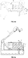
- FIG. 2a is an external view of ink cartridge refilling device 1 of the embodiment
- FIG. 2b is a schematic diagram of the ink cartridge refilling device 1, in the opened state, of the embodiment.
- the ink cartridge refilling device 1 comprises an ink container 10, an ink injection channel 11, an air inlet channel 12, an aspirator 13, an ink cartridge positioning mechanism 15 and a cover component 14, wherein the ink container 10 is used for storing ink to be conveyed to the ink cartridge to be refilled 2 during the refilling
- the ink injection channel 11 is arranged inside the ink container 10 and used for conveying the ink in the ink container to the ink cartridge 2 and comprises an outlet end 111 which is connected with an ink outlet 22 of the ink cartridge 2 and an inlet end 112 which introduces the ink to flow into the channel from the ink container 10
- the air inlet channel 12 is arranged on the ink container 10 and used for replenishing air into the ink container 10 from the outside and comprises an air
- the positioning mechanism 15 and the ink container 10 are preferably integrated into a whole by injection molding.
- clamping grooves 151a and 151b are respectively arranged on both sidewalls of the positioning mechanism 15.
- the cover component 14 is arranged on the ink container 10 and used for fixing the ink cartridge 2 into the ink cartridge refilling device 1.
- the cover component 14 is preferably connected with the ink cartridge positioning mechanism 15 through a rotating shaft. As illustrated in FIG.
- one end of the cover component 14 is a connecting end 147 which is connected with the positioning mechanism 15 through the rotating shaft, namely the cover component 14 can be rotated to a certain angle around the positioning mechanism 15; and the other end of the cover component 14 is a free end 148.
- two extended clamp hooks 145a and 145b which are extended from the inside of the cover component 14 are also arranged near the free end 148 and can be clamped with the two clamping grooves 151a and 151b of the ink cartridge positioning mechanism 15, so that the cover component 14 can fix the ink cartridge 2 on the ink cartridge refilling device 1 after the ink cartridge 2 is assembled into the ink cartridge positioning mechanism 15.
- the first sealing section is preferably composed of a convex section 141 and an elastic sleeve 142, wherein the convex section 141 is convex from the inside of the cover component 14 and arranged inside the cover component 14, at a position corresponding to the air inlet 23 of the ink cartridge 2; to be specific, the convex section 141 can cover the upper part of the air inlet 23 when the cover component 14 and the ink cartridge positioning mechanism 15 are clamped with each other; and the elastic sleeve 142 is made of elastic materials such as silica gel and rubber, has the same dimension with the convex section 141, and is used for enclosing the convex section 141.
- the diameter of the concave section is equivalent to the outside diameter of the air inlet end 121 of the air inlet channel 12, and the outside diameter of the sealing element 144 is equivalent to the inside diameter of the extended section 143. That is to say, the sealing element 144 is assembled inside the extended section 133 in general and can be used to directly seal the air inlet channel 12 when the cover component 14 and the positioning mechanism 15 are clamped with each other.
- the sealing element 144 can also be a gasket of which the area is equivalent to that of the end face of the extended section 143, and the gasket is welded on the end face of the extended section 143, which is in contact with the air inlet channel 12; and the sealing element 144 can also be a silica gel sleeve which is engaged with the extended section 143.
- the first sealing section and the second sealing section can seal the air inlet 23 of the ink cartridge 2 and the second sealing section can seal the air inlet channel 12 of the refilling device 1, so that the outside air cannot flow into the ink cartridge 2 and the ink container 10, thus a closed space is formed between the ink cartridge 2 and the ink container 10 which are isolated from the outside.
- the first sealing section and the second sealing section can limit the movement of the ink cartridge 2 on the refilling device 1, namely the ink cartridge 2 cannot move upwards, thus the complete fixation of the ink cartridge 2 inside the ink cartridge refilling device 2 is guaranteed.
- the air inlet channel 12 is opened first, and then the sealing of the ink cartridge 2 is canceled. Therefore, after the ink refilling is completed and the refilling device 1 is opened, the air can be replenished into the ink container 10 first and then replenished into the ink cartridge 2, so that redundant ink can be removed, thus the reflowing of redundant ink in the ink cartridge 2 into the ink container 10 can be prevented.
- the distance between the extended section 143 and the convex section 141 can be determined according to different ink cartridge structures.
- the deformation of the elastic sleeve 142 in the embodiment is preferably larger than that of the sealing element 144, so that the ink cartridge 2 can be still maintained to be sealed by the first sealing section after the air inlet channel 12 is opened by the second sealing section.
- the deformation of the first sealing section is also larger than that of the second sealing section, so that the first elastic pad can be still maintained to be in the sealed state after the second elastic pad is opened, namely the thickness of the first sealing section is larger than that of the second sealing section.
- a through hole 146 is reserved on the cover component 14, at a position corresponding to the ink injection opening 24 of the ink cartridge 2.
- the diameter of the through hole 146 is equivalent to that of the ink injection opening 24, so that the suction nozzle 136 of the aspirator 13 is connected with the ink injection opening 24 through the through hole 146 during the refilling.
- a gasket 113 is arranged at the outlet end 111 of the ink injection channel 11 and made of elastic materials such as silica gel and rubber, and can be a common seal ring which is taken off during the refilling and assembled after the refilling.
- the gasket 113 is preferably a self-closing gasket, and a self-closing slot is reserved on the self-closing gasket.
- the self-closing gasket is in the closed state at normal times and can only be opened when the pressure difference at both sides of the ink cartridge 2 and the ink container 10 reaches the predetermined value.
- a friction section 16 is also arranged at the free end 148 of the cover component 14 and formed by a plurality of concave-convex groove parts. The object of the friction section 16 is to increase the friction force between a hand of a user and the cover component 14 and guarantee that the hand of the user cannot slide easily when the user handles the cover component 14 for opening or closing the refilling device 1.
- the ink cartridge refilling device 1 is preferably made of transparent materials in the embodiment.
- FIGS. 4a to 4e The process of refilling ink into the ink cartridge 2 by adoption of the ink cartridge refilling device 1 is illustrated according to FIGS. 4a to 4e .
- the rubber plug 18 assembled into the ink injection opening 24 can be a common elastic seal ring.
- the rubber plug 18 is preferably a self-closing seal ring which can be opened or closed according to the pressure difference between the inside and the outside of the ink cartridge.
- the self-closing seal ring is in the opened state when the aspirator 13 is inserted and is in the closed state when the aspirator 13 is not inserted.
- the “matter balance principle" is followed during the ink refilling, namely the mass of matters flowing out of a container is equivalent to that of matters flowing into the container.
- the volume of the ink flowing out of the ink storage cavity of the refilling tool mentioned in the background of the invention is equivalent to the volume of air replenished into the ink storage cavity.
- the ink container 10 is maintained to be in the closed state during the sucking and air is not replenished into the ink container 10.
- the ink refilling of the ink cartridge 2 enables the pressure in the ink container 10 to be unbalanced and is continued under the condition of unbalanced pressure in the ink container 10, namely the refilling of ink into the ink cartridge and the replenishing of air into the ink container are not carried out at the same time.
- the reason for adopting the mode is as follows: in the prior art, the sponge 211 and the cotton core 221 in the ink cartridge 2 tend to be in the supersaturated state after the ink refilling, namely there is redundant ink in the negative-pressure cavity 21, thus the ink dropping phenomenon tends to occur when the ink cartridge 2 is taken off at the time; but in the technical proposal, a closed space is formed between the ink cartridge 2 and the ink container 10 during the refilling, so that large negative pressure can be formed in the ink container 10 when air in the ink cartridge 2 is sucked to enable ink in the ink container 10 to flow into the ink cartridge 2 and air is not replenished into the ink container 10 in time.
- the air can be replenished into the negative-pressure cavity 21 through the air inlet 23, and redundant ink in the sponge 211 and the cotton core 221 can flow into the ink container 10 at the time due to the matter balance principle, so that the sponge 211 and the cotton core 221 are in the unsaturated state, thus the ink dropping phenomenon cannot occur when the ink cartridge 2 is taken off.
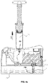
- FIG. 5 is a schematic diagram of the ink cartridge refilling device, in the opened state, of the embodiment. Same components in the embodiment have same symbols with those in the embodiment 1.
- a mandrel 17 used for removing a steel ball for sealing the ink injection opening 24 is arranged at the through hole 146 of the cover component 14; a concave face which is engaged with the steel ball of the ink injection opening 24 is arranged at the top of the mandrel 17; a plurality of linear grooves at different lengths are arranged on the side face of the mandrel 17, so that the concave face and the side face of the mandrel 17 are combined to form an edge provided with a plurality of blade parts.
- the mandrel 17 is arranged to be movable, and to be specific, arranged to be able to slide back and forth on the cover component 14, namely the mandrel 17 can slide back and forth at the opening position and the non-opening position. It should be understood by those skilled in the art that the mandrel 17 can also be arranged to be able to be removed from the cover component 14. That is to say, firstly, the mandrel 17 is taken off after the opening action is completed; secondly, a refilling tool is utilized for ink refilling; and thirdly, the mandrel 17 is reset after the ink refilling.
- a delay action component is added in the embodiment on the basis of the embodiments 1 and 2 and used for guaranteeing that the air inlet channel is opened by the second sealing section while the ink cartridge to be refilled is still sealed by the first sealing section.
- the delay action component is an elastic component which is engaged with the first sealing section.
- the elastic component in the embodiment is a spiral spring 19.
- the first sealing section is still in the state of sealing the air inlet 23 when the second sealing section is driven to open the air inlet channel 12 due to the application of the compressive force and can only be detached from the air inlet 23 when the compressive force is canceled after the cover component 14 is rotated to a certain angle and the spring 19 moves upwards along with the movement of the cover component 14.
- the first sealing section illustrated in the above process can be the first elastic pad, can be the convex section and the elastic sleeve, and can also be other similar sealing components. The structure of the first sealing section is numerous and is not explained in detail here.
- the ink cartridge can also be an ink cartridge without an ink storage cavity and only with a sponge, namely the refilling device and the refilling method are also applicable to the ink cartridge for refilling.
- the extended clamp hook(s) can be one or more than two and the position and the number of the clamping grooves correspond to those of the extended clamp hook(s).
- cover component can also perform up-and-down parallel movement relative to the ink cartridge positioning mechanism, and herein the cover component and the ink cartridge positioning mechanism can also be connected with each other through the engagement of the extended clamp hooks and the clamping grooves.
- the sealing and opening actions of the first sealing section and the second sealing section on the cover component can be performed at the same time, namely the opening of the air inlet channel and the canceling of the sealing of the ink cartridge after the ink refilling can be carried out at the same time. But in the case, more redundant ink in the sponge can flow back to the ink container compared with the embodiment 1 or 2, and the ink dropping phenomenon can also be prevented.
- the ink cartridge refilling device can also be made of non-transparent materials. If so, it can be determined that the ink cartridge is filled with ink when there is ink in the aspirator during the ink refilling, and a user only needs to enable redundant ink in the aspirator to be refilled into the ink container again after the ink refilling.
Landscapes
- Ink Jet (AREA)
- Basic Packing Technique (AREA)
Claims (22)
- Dispositif de recharge de cartouche d'encre à pression négative (1,13) pour recharger de l'encre dans une cartouche d'encre (2), ledit dispositif de recharge de cartouche d'encre comprenant :- un conteneur d'entre (10) pour stocker l'encre à recharger ;- un canal d'injection d'encre (11) communiquant avec ledit conteneur d'entre (10) et transportant ladite encre dudit conteneur d'encre (10) à ladite cartouche d'encre (2) ;- un canal d'entrée d'air (12) communiquant avec ledit conteneur d'encre (10) et reconstituant l'air dans ledit conteneur d'encre (10) ;- un aspirateur (13) pour aspirer l'air hors de ladite cartouche d'encre (2) ; et- un composant de couvercle (14), dans lequel ledit composant de couvercle (14) est pourvu d'une première section d'isolation étanche (142) pour isoler de manière étanche une entrée d'air (23) de ladite cartouche d'encre (2) ;caractérisé en ce que
ledit composant de couvercle (14) est pourvu d'une seconde section d'isolation étanche (144) pour isoler de manière étanche ledit canal d'entrée d'air (12). - Dispositif de recharge de cartouche d'encre (1,13) selon la revendication 1, dans lequel ledit dispositif de recharge de cartouche d'encre (1,13) comprend aussi un mécanisme de positionnement (15) de cartouche d'encre (2) pour positionner ladite cartouche d'encre (2) sur ledit dispositif de recharge de cartouche d'encre (1 ;13); et ledit mécanisme de positionnement (15) de cartouche d'encre (2) est raccordé audit composant de couvercle (14) via un arbre rotatif.
- Dispositif de recharge de cartouche d'encre (1,13) selon la revendication 2, dans lequel ladite première section d'isolation étanche (142) est plus proche dudit arbre rotatif que ladite seconde section d'isolation étanche (144).
- Dispositif de recharge de cartouche d'encre (1,13) selon une des revendications 1 à 3, dans lequel ladite première section d'isolation étanche (142) est un premier tampon élastique qui est disposé sur ledit composant de couvercle (14) et ladite seconde section d'isolation étanche (144) est un second tampon élastique qui est disposé sur ledit composant de couvercle (14).
- Dispositif de recharge de cartouche d'encre (1,13) selon une des revendications 1 à 3, dans lequel ladite première section d'isolation étanche (142) est constituée d'une section convexe qui est convexe à partir dudit composant de couvercle (14) et d'un manchon élastique qui est mis en prise avec ladite section convexe.
- Dispositif de recharge de cartouche d'encre (1,13) selon une des revendications 1 à 5, dans lequel ladite seconde section d'isolation étanche est constituée d'une section étendue qui est étendue à partir dudit composant de couvercle (14) et un élément d'isolation étanche qui est mis en prise avec ladite section étendue.
- Dispositif de recharge de cartouche d'encre (1,13) selon une des revendications 1 à 6, dans lequel ledit dispositif de recharge de cartouche d'encre est aussi pourvu d'un composant de retard d'action qui permet à ladite première section d'isolation étanche (142) d'être toujours dans un état d'isolation étanche de ladite entrée d'air (23) de ladite cartouche d'encre (2) après que ledit composant de couvercle (14) est amené dans une position dans laquelle ledit canal d'entrée d'air (12) dudit dispositif de recharge de cartouche d'entre n'est plus isolé de manière étanche par ladite seconde section d'isolation étanche (144).
- Dispositif de recharge de cartouche d'encre (1,13) selon la revendication 7, dans lequel ledit composant de retard d'action est un composant élastique qui est raccordé à ladite première section d'isolation étanche.
- Dispositif de recharge de cartouche d'encre (1,13) selon la revendication 4, dans lequel une déformation dudit premier tampon élastique est supérieure à une déformation dudit second tampon élastique, lorsque ladite cartouche d'encre (2) est fixée par ledit composant de couvercle (14) dans ledit dispositif de recharge de cartouche d'encre.
- Dispositif de recharge de cartouche d'encre (1,13) selon la revendication 6, dans lequel une déformation dudit manchon élastique est supérieure à une déformation dudit élément d'isolation étanche, lorsque ladite cartouche d'encre (2) est fixée par ledit composant de couvercle (14) dans ledit dispositif de recharge de cartouche d'encre.
- Dispositif de recharge de cartouche d'encre (1,13) selon une quelconque des revendications 1 à 10, dans lequel ledit composant de couvercle (14) est aussi pourvu de crochets de serrage étendus et ledit mécanisme de positionnement est pourvu de rainures de serrage qui sont mises en prise avec lesdits crochets de serrage étendus.
- Système de recharge de cartouche d'encre à pression négative (1,2,13), comprenant une cartouche d'encre (2) et un dispositif de recharge de cartouche d'encre (1,13) selon une quelconque des revendications 1 à 11.
- Système de recharge de cartouche d'encre à pression négative (1,2,13) selon la revendication 12, dans lequel ladite cartouche d'encre (2) comprend :- une cavité (20, 21) pour stocker de l'encre,- une éponge (211) disposée à l'intérieur de ladite cavité pour conserver une pression négative dans ladite cartouche d'encre (2),- une sortie d'encre (22) pour transporter ladite encre dudit conteneur d'encre (10) vers ladite cartouche d'encre (2) et pour libérer ladite encre de ladite cavité vers l'extérieur de ladite cartouche d'encre (2) et- ladite entrée d'air (23) pour reconstituer l'air dans ladite cavité, et- une ouverture d'injection d'encre (24) pouvant être raccordée audit aspirateur (13) pour aspirer de l'air dans ladite cavité (20).
- Système de recharge de cartouche d'encre à pression négative (1,2,13) selon la revendication 13, dans lequel ladite cavité est divisée en ladite cavité (20) de réception de ladite encre et une cavité à pression négative (21) pour recevoir ladite éponge (211).
- Système de recharge de cartouche d'encre à pression négative (1,2,13) selon une des revendications 12 à 14, dans lequel ladite première section d'isolation étanche est disposée sur ledit composant de couvercle (14), à une position correspondant à ladite entrée d'air (23) de ladite cartouche d'encre (2).
- Système de recharge de cartouche d'encre à pression négative (1,2,13) selon la revendication 15, dans lequel un alésage traversant (146) est réservé sur ledit composant de couvercle (14), à une position correspondant à ladite ouverture d'injection d'encre (24) de ladite cartouche d'encre (2).
- Système de recharge de cartouche d'encre à pression négative (1,2,13) selon la revendication 16, dans lequel un mandrin mobile (17) est disposé au niveau dudit alésage traversant (146) et utilisé pour éliminer un élément d'isolation étanche (18) de ladite cartouche d'encre (2), qui isole de manière étanche ladite ouverture d'injection d'encre (24) avant l'élimination dudit élément d'isolation étanche (18) de ladite cartouche d'encre (2).
- Procédé de recharge pour utiliser un système de recharge de cartouche d'encre (1,2,13) selon une quelconque des revendications 12 à 17 pour recharger ladite cartouche d'encre (2), comprenant les étapes suivantes de :- formation d'un espace fermé entre ladite cartouche d'encre (2) et ledit conteneur d'encre (10) en• raccordant ledit canal d'injection d'encre (11) à une sortie d'encre (22) de ladite cartouche d'encre (2) en positionnant ladite cartouche d'encre (2) sur ledit dispositif de recharge de cartouche d'encre,• isolant de manière étanche ladite entrée d'air (23) de ladite cartouche d'encre (2),• isolant de manière étanche ledit canal d'entrée d'air (12) dudit dispositif de recharge de cartouche d'encre,• raccordant ledit aspirateur (13) à une ouverture d'injection (24) de ladite cartouche d'encre (2) ;- aspiration d'air par ledit aspirateur (13) hors de ladite cartouche d'encre (2) via ladite ouverture d'injection d'encre (24) de ladite cartouche d'encre (2) ; et- arrêt de ladite isolation étanche dudit espace fermé en ouvrant ledit canal d'entrée d'air (12).
- Procédé de recharge selon la revendication 18, comprenant aussi l'étape suivante avant la première étape du procédé de recharge selon la revendication 18 :- ouverture de ladite ouverture d'injection d'encre (24) de ladite cartouche d'encre (2) et assemblage d'un bouchon en caoutchouc (18) dans ladite ouverture d'injection d'encre (24).
- Procédé de recharge selon la revendication 18, dans lequel à la troisième étape du procédé de recharge selon la revendication 18 ledit canal d'entrée d'air (12) est ouvert en premier, et l'isolation étanche de ladite entrée d'air (23) de ladite cartouche d'encre (2) est ensuite arrêtée.
- Procédé de recharge selon la revendication 18, dans lequel à la troisième étape du procédé de recharge selon la revendication 18 ledit canal d'entrée d'air (12) est ouvert et simultanément l'isolation étanche de ladite entrée d'air (23) de ladite cartouche d'encre (2) est arrêtée.
- Procédé de recharge selon une quelconque des revendications 19 à 21, dans lequel ledit procédé de recharge comprend aussi l'étape suivante après que ladite troisième étape est terminée :- retrait de ladite cartouche d'encre (2) dudit dispositif de recharge de cartouche d'encre et isolation étanche à nouveau dudit canal d'entrée d'air (12).
Applications Claiming Priority (2)
| Application Number | Priority Date | Filing Date | Title |
|---|---|---|---|
| CN201010603099.6A CN102529386B (zh) | 2010-12-22 | 2010-12-22 | 一种墨盒填充装置、墨盒填充系统及相应的墨盒填充方法 |
| PCT/CN2011/075494 WO2012083644A1 (fr) | 2010-12-22 | 2011-06-09 | Dispositif et système de remplissage de cartouche d'encre et procédé associé |
Publications (3)
| Publication Number | Publication Date |
|---|---|
| EP2657032A1 EP2657032A1 (fr) | 2013-10-30 |
| EP2657032A4 EP2657032A4 (fr) | 2017-01-11 |
| EP2657032B1 true EP2657032B1 (fr) | 2018-02-28 |
Family
ID=46313093
Family Applications (1)
| Application Number | Title | Priority Date | Filing Date |
|---|---|---|---|
| EP11851601.2A Not-in-force EP2657032B1 (fr) | 2010-12-22 | 2011-06-09 | Dispositif et système de remplissage de cartouche d'encre et procédé associé |
Country Status (5)
| Country | Link |
|---|---|
| US (1) | US9050813B2 (fr) |
| EP (1) | EP2657032B1 (fr) |
| JP (2) | JP5940088B2 (fr) |
| CN (1) | CN102529386B (fr) |
| WO (1) | WO2012083644A1 (fr) |
Families Citing this family (15)
| Publication number | Priority date | Publication date | Assignee | Title |
|---|---|---|---|---|
| CN102717599A (zh) * | 2012-06-29 | 2012-10-10 | 珠海天威飞马打印耗材有限公司 | 墨水容器及灌墨装置 |
| JP6048004B2 (ja) | 2012-07-23 | 2016-12-21 | セイコーエプソン株式会社 | カートリッジ |
| US9776418B2 (en) | 2012-07-23 | 2017-10-03 | Seiko Epson Corporation | Method and apparatus for manufacturing cartridge |
| US10647123B2 (en) | 2012-07-23 | 2020-05-12 | Seiko Epson Corporation | Refilled cartridge and method for manufacturing refilled cartridge |
| JP6069964B2 (ja) * | 2012-07-23 | 2017-02-01 | セイコーエプソン株式会社 | カートリッジの製造方法、注入キット、及び、注入装置 |
| US9421781B2 (en) * | 2012-10-15 | 2016-08-23 | Seiko Epson Corporation | Recording apparatus |
| JP2015077731A (ja) * | 2013-10-17 | 2015-04-23 | キヤノン株式会社 | インク充填装置およびインク充填方法 |
| JP6459673B2 (ja) * | 2014-07-25 | 2019-01-30 | セイコーエプソン株式会社 | プリンター |
| CN107206806B (zh) * | 2015-01-29 | 2019-09-17 | 惠普发展公司,有限责任合伙企业 | 启动使用打印系统的方法及打印系统 |
| US9878894B1 (en) * | 2016-07-08 | 2018-01-30 | Funai Electric Co., Ltd. | Fluid delivery devices having improved efficiency in delivering fluid with reduced wastage of fluid |
| US11396188B2 (en) * | 2019-05-23 | 2022-07-26 | Hewlett-Packard Development Company, L.P. | Selectable fill mode of printing device having reservoir fillable from external colorant supply |
| CN213355232U (zh) * | 2020-03-27 | 2021-06-04 | 珠海纳思达企业管理有限公司 | 包装组件 |
| CN113733756B (zh) * | 2021-09-30 | 2023-04-11 | 珠海纳思达企业管理有限公司 | 墨盒填充装置和墨盒填充方法 |
| JP7793979B2 (ja) * | 2021-12-27 | 2026-01-06 | セイコーエプソン株式会社 | 液体収容容器、および液体収容容器に液体を収容させる方法 |
| CN117207676B (zh) * | 2023-11-08 | 2024-01-16 | 珠海杨杋科技有限公司 | 一种新型连供墨盒 |
Family Cites Families (29)
| Publication number | Priority date | Publication date | Assignee | Title |
|---|---|---|---|---|
| IT1258135B (it) * | 1992-12-28 | 1996-02-20 | Olivetti Canon Ind Spa | Dispositivo per conservare e mantenere rifornite d'inchiostro le cartucce di una stampante a getto d'inchiostro. |
| US5400573A (en) * | 1993-12-14 | 1995-03-28 | Crystal; Richard G. | Kit and method for opening, refilling and sealing a cartridge |
| JP3613346B2 (ja) * | 1994-09-16 | 2005-01-26 | セイコーエプソン株式会社 | インクカートリッジへのインクの充填方法 |
| JPH08281964A (ja) * | 1995-04-19 | 1996-10-29 | Kao Corp | インクカートリッジへのインク補充装置 |
| US5838352A (en) * | 1995-11-24 | 1998-11-17 | Smith Corona Corporation | Ink cartridge refilling device and station for cartridges and gravity feed ink bottle |
| US5709253A (en) * | 1996-07-30 | 1998-01-20 | Procubed Corporation | Method for refilling an inkjet cartridge and apparatus to modify a cartridge with a negative pressure reservoir |
| JP3513377B2 (ja) * | 1996-12-05 | 2004-03-31 | キヤノン株式会社 | 液体収容容器への液体充填方法、該充填方法を実施するための充填ユニットと該充填方法により製造された液体収容容器、及び液体吐出記録装置 |
| ATE267707T1 (de) * | 1999-03-29 | 2004-06-15 | Seiko Epson Corp | Verfahren und vorrichtung zum befüülen von tintenpatronen mit tinte |
| US6640843B2 (en) * | 2000-09-29 | 2003-11-04 | Lee Yong-Soo | Ink refilling apparatus and method for cartridge of ink jet printer |
| CN2467325Y (zh) * | 2001-01-21 | 2001-12-26 | 刘文荧 | 喷墨打印机墨匣的墨水填充器 |
| JP3802360B2 (ja) * | 2001-03-22 | 2006-07-26 | シャープ株式会社 | インク充填装置 |
| JP4193435B2 (ja) * | 2002-07-23 | 2008-12-10 | ブラザー工業株式会社 | インクカートリッジ、および、そのインク充填方法 |
| US6386691B1 (en) * | 2001-06-05 | 2002-05-14 | Win-Yin Liu | Ink cartridge of a printer facilitating second refilling |
| CN100352657C (zh) * | 2003-02-26 | 2007-12-05 | 付刚 | 喷墨打印机墨盒再生自动墨水填充装置及其方法 |
| ITTO20030303A1 (it) * | 2003-04-17 | 2004-10-18 | Tecnost Sistemi S P A | Stazione di custodia e rifornimento di inchiostro di |
| US7344215B2 (en) * | 2004-09-28 | 2008-03-18 | E. I. Du Pont De Nemours And Company | Inkjet cartridge refilling machine and method |
| TW200640701A (en) * | 2005-05-31 | 2006-12-01 | Just Print Technology Co Ltd | Ink-filling mechanism for inkjet cartridge |
| TWM282839U (en) * | 2005-07-29 | 2005-12-11 | Yi-Tzung Yan | Unsophisticated filling component for ink cartridge |
| US7690741B2 (en) * | 2006-10-30 | 2010-04-06 | Hewlett-Packard Development Company, L.P. | Introducing ink into an ink cartridge |
| JP2008307853A (ja) * | 2007-06-18 | 2008-12-25 | Canon Inc | インク再充填方法 |
| DE202007019225U1 (de) * | 2007-08-06 | 2011-05-05 | Pelikan Hardcopy Production Ag | Vorrichtung zur Wiederbefüllung einer Tintenpatrone für einen Tintenstrahldrucker |
| CN101117053B (zh) * | 2007-09-01 | 2013-05-01 | 珠海天威飞马打印耗材有限公司 | 灌墨装置及使用该灌墨装置的灌墨方法 |
| CN201483892U (zh) * | 2009-08-05 | 2010-05-26 | 珠海纳思达电子科技有限公司 | 一种将墨水再填充至墨盒的墨水填充工具 |
| CN201645992U (zh) * | 2009-11-26 | 2010-11-24 | 珠海纳思达电子科技有限公司 | 一种墨盒填充装置用密封垫及墨盒填充装置 |
| CN102233736B (zh) * | 2010-05-01 | 2015-01-07 | 珠海纳思达企业管理有限公司 | 一种墨盒填充装置及利用该装置进行墨水填充的墨盒填充方法 |
| CN201685529U (zh) * | 2010-05-12 | 2010-12-29 | 珠海纳思达企业管理有限公司 | 墨盒填充装置 |
| CN102371767B (zh) * | 2010-08-12 | 2014-06-25 | 珠海纳思达企业管理有限公司 | 一种负压式墨盒填充装置、系统及填充方法 |
| CN201998564U (zh) * | 2010-12-22 | 2011-10-05 | 珠海纳思达企业管理有限公司 | 一种墨盒填充装置及墨盒填充系统 |
| US8465136B2 (en) * | 2011-07-31 | 2013-06-18 | Dongguan Master Ink Co., Ltd. | Ink cartridge refill apparatus |
-
2010
- 2010-12-22 CN CN201010603099.6A patent/CN102529386B/zh not_active Expired - Fee Related
-
2011
- 2011-06-09 JP JP2013545015A patent/JP5940088B2/ja not_active Expired - Fee Related
- 2011-06-09 US US13/636,113 patent/US9050813B2/en active Active
- 2011-06-09 EP EP11851601.2A patent/EP2657032B1/fr not_active Not-in-force
- 2011-06-09 WO PCT/CN2011/075494 patent/WO2012083644A1/fr not_active Ceased
-
2016
- 2016-05-12 JP JP2016096207A patent/JP6078676B2/ja active Active
Non-Patent Citations (1)
| Title |
|---|
| None * |
Also Published As
| Publication number | Publication date |
|---|---|
| JP2016147501A (ja) | 2016-08-18 |
| EP2657032A4 (fr) | 2017-01-11 |
| JP6078676B2 (ja) | 2017-02-08 |
| EP2657032A1 (fr) | 2013-10-30 |
| CN102529386B (zh) | 2015-12-09 |
| US20130255826A1 (en) | 2013-10-03 |
| JP5940088B2 (ja) | 2016-06-29 |
| US9050813B2 (en) | 2015-06-09 |
| CN102529386A (zh) | 2012-07-04 |
| JP2014500168A (ja) | 2014-01-09 |
| WO2012083644A1 (fr) | 2012-06-28 |
Similar Documents
| Publication | Publication Date | Title |
|---|---|---|
| EP2657032B1 (fr) | Dispositif et système de remplissage de cartouche d'encre et procédé associé | |
| US10183495B2 (en) | Liquid supply device, printing apparatus and liquid ejection system | |
| JP3658328B2 (ja) | 液体収容容器への液体再充填方法および装置 | |
| EP2604434B1 (fr) | Appareil, système et procédé de remplissage à pression négative pour cartouche d'encre | |
| KR970064939A (ko) | 인쇄 시스템과 프린트 카트리지 보충방법 | |
| CN201922646U (zh) | 墨盒填充装置和墨盒填充组件 | |
| WO2012019393A1 (fr) | Appareil de remplissage à pression négative pour cartouche d'encre | |
| JP2006183621A (ja) | チューブポンプ、インクジェット記録装置、及びインク供給方法 | |
| CN201483892U (zh) | 一种将墨水再填充至墨盒的墨水填充工具 | |
| CN201784253U (zh) | 一种负压式墨盒填充装置 | |
| CN101623956B (zh) | 一种将墨水再填充至墨盒的方法及填充工具 | |
| US20010015743A1 (en) | Method for manufacturing ink tank, ink tank, ink jet cartridge, and ink jet recording apparatus | |
| JP5719429B2 (ja) | インクカートリッジ充填装置および当該装置を用いたインクカートリッジ充填方法 | |
| JP5975420B2 (ja) | 反転式印判 | |
| CN201900800U (zh) | 喷墨墨盒用墨水补充装置 | |
| CN201998564U (zh) | 一种墨盒填充装置及墨盒填充系统 | |
| WO2007109925A1 (fr) | Cartouche d'encre à support de cartouche d'encre | |
| CN201728898U (zh) | 液体容器 | |
| CN213973224U (zh) | 一种不漏墨不滴墨的墨盒 | |
| CN218171809U (zh) | 墨水填充装置 | |
| CN220904437U (zh) | 一种墨仓以及一种墨水补充系统 | |
| JP3077213U (ja) | バブルジェットプリンターインクカートリッジのインク充填用具 | |
| JP3082141U (ja) | 第二次充填の容易なプリンタ用インクカートリッジ | |
| CN201745249U (zh) | 一种墨盒的墨水填充装置 | |
| JP3063080U (ja) | バブルジェットプリンタ―インクカ―トリッジの簡易クランプホルダ及びインク補充装置 |
Legal Events
| Date | Code | Title | Description |
|---|---|---|---|
| PUAI | Public reference made under article 153(3) epc to a published international application that has entered the european phase |
Free format text: ORIGINAL CODE: 0009012 |
|
| 17P | Request for examination filed |
Effective date: 20130524 |
|
| AK | Designated contracting states |
Kind code of ref document: A1 Designated state(s): AL AT BE BG CH CY CZ DE DK EE ES FI FR GB GR HR HU IE IS IT LI LT LU LV MC MK MT NL NO PL PT RO RS SE SI SK SM TR |
|
| DAX | Request for extension of the european patent (deleted) | ||
| RA4 | Supplementary search report drawn up and despatched (corrected) |
Effective date: 20161208 |
|
| RIC1 | Information provided on ipc code assigned before grant |
Ipc: B41J 2/175 20060101AFI20161202BHEP |
|
| GRAP | Despatch of communication of intention to grant a patent |
Free format text: ORIGINAL CODE: EPIDOSNIGR1 |
|
| INTG | Intention to grant announced |
Effective date: 20171102 |
|
| RIN1 | Information on inventor provided before grant (corrected) |
Inventor name: QIN, LEI Inventor name: NIE, BING |
|
| GRAS | Grant fee paid |
Free format text: ORIGINAL CODE: EPIDOSNIGR3 |
|
| GRAA | (expected) grant |
Free format text: ORIGINAL CODE: 0009210 |
|
| AK | Designated contracting states |
Kind code of ref document: B1 Designated state(s): AL AT BE BG CH CY CZ DE DK EE ES FI FR GB GR HR HU IE IS IT LI LT LU LV MC MK MT NL NO PL PT RO RS SE SI SK SM TR |
|
| REG | Reference to a national code |
Ref country code: GB Ref legal event code: FG4D Ref country code: CH Ref legal event code: EP |
|
| REG | Reference to a national code |
Ref country code: AT Ref legal event code: REF Ref document number: 973679 Country of ref document: AT Kind code of ref document: T Effective date: 20180315 |
|
| REG | Reference to a national code |
Ref country code: IE Ref legal event code: FG4D |
|
| REG | Reference to a national code |
Ref country code: DE Ref legal event code: R096 Ref document number: 602011046149 Country of ref document: DE |
|
| REG | Reference to a national code |
Ref country code: NL Ref legal event code: MP Effective date: 20180228 |
|
| REG | Reference to a national code |
Ref country code: LT Ref legal event code: MG4D |
|
| REG | Reference to a national code |
Ref country code: AT Ref legal event code: MK05 Ref document number: 973679 Country of ref document: AT Kind code of ref document: T Effective date: 20180228 |
|
| PG25 | Lapsed in a contracting state [announced via postgrant information from national office to epo] |
Ref country code: HR Free format text: LAPSE BECAUSE OF FAILURE TO SUBMIT A TRANSLATION OF THE DESCRIPTION OR TO PAY THE FEE WITHIN THE PRESCRIBED TIME-LIMIT Effective date: 20180228 Ref country code: CY Free format text: LAPSE BECAUSE OF FAILURE TO SUBMIT A TRANSLATION OF THE DESCRIPTION OR TO PAY THE FEE WITHIN THE PRESCRIBED TIME-LIMIT Effective date: 20180228 Ref country code: LT Free format text: LAPSE BECAUSE OF FAILURE TO SUBMIT A TRANSLATION OF THE DESCRIPTION OR TO PAY THE FEE WITHIN THE PRESCRIBED TIME-LIMIT Effective date: 20180228 Ref country code: ES Free format text: LAPSE BECAUSE OF FAILURE TO SUBMIT A TRANSLATION OF THE DESCRIPTION OR TO PAY THE FEE WITHIN THE PRESCRIBED TIME-LIMIT Effective date: 20180228 Ref country code: NL Free format text: LAPSE BECAUSE OF FAILURE TO SUBMIT A TRANSLATION OF THE DESCRIPTION OR TO PAY THE FEE WITHIN THE PRESCRIBED TIME-LIMIT Effective date: 20180228 Ref country code: FI Free format text: LAPSE BECAUSE OF FAILURE TO SUBMIT A TRANSLATION OF THE DESCRIPTION OR TO PAY THE FEE WITHIN THE PRESCRIBED TIME-LIMIT Effective date: 20180228 Ref country code: NO Free format text: LAPSE BECAUSE OF FAILURE TO SUBMIT A TRANSLATION OF THE DESCRIPTION OR TO PAY THE FEE WITHIN THE PRESCRIBED TIME-LIMIT Effective date: 20180528 |
|
| PG25 | Lapsed in a contracting state [announced via postgrant information from national office to epo] |
Ref country code: AT Free format text: LAPSE BECAUSE OF FAILURE TO SUBMIT A TRANSLATION OF THE DESCRIPTION OR TO PAY THE FEE WITHIN THE PRESCRIBED TIME-LIMIT Effective date: 20180228 Ref country code: BG Free format text: LAPSE BECAUSE OF FAILURE TO SUBMIT A TRANSLATION OF THE DESCRIPTION OR TO PAY THE FEE WITHIN THE PRESCRIBED TIME-LIMIT Effective date: 20180528 Ref country code: GR Free format text: LAPSE BECAUSE OF FAILURE TO SUBMIT A TRANSLATION OF THE DESCRIPTION OR TO PAY THE FEE WITHIN THE PRESCRIBED TIME-LIMIT Effective date: 20180529 Ref country code: RS Free format text: LAPSE BECAUSE OF FAILURE TO SUBMIT A TRANSLATION OF THE DESCRIPTION OR TO PAY THE FEE WITHIN THE PRESCRIBED TIME-LIMIT Effective date: 20180228 Ref country code: SE Free format text: LAPSE BECAUSE OF FAILURE TO SUBMIT A TRANSLATION OF THE DESCRIPTION OR TO PAY THE FEE WITHIN THE PRESCRIBED TIME-LIMIT Effective date: 20180228 Ref country code: LV Free format text: LAPSE BECAUSE OF FAILURE TO SUBMIT A TRANSLATION OF THE DESCRIPTION OR TO PAY THE FEE WITHIN THE PRESCRIBED TIME-LIMIT Effective date: 20180228 |
|
| PG25 | Lapsed in a contracting state [announced via postgrant information from national office to epo] |
Ref country code: AL Free format text: LAPSE BECAUSE OF FAILURE TO SUBMIT A TRANSLATION OF THE DESCRIPTION OR TO PAY THE FEE WITHIN THE PRESCRIBED TIME-LIMIT Effective date: 20180228 Ref country code: RO Free format text: LAPSE BECAUSE OF FAILURE TO SUBMIT A TRANSLATION OF THE DESCRIPTION OR TO PAY THE FEE WITHIN THE PRESCRIBED TIME-LIMIT Effective date: 20180228 Ref country code: PL Free format text: LAPSE BECAUSE OF FAILURE TO SUBMIT A TRANSLATION OF THE DESCRIPTION OR TO PAY THE FEE WITHIN THE PRESCRIBED TIME-LIMIT Effective date: 20180228 Ref country code: EE Free format text: LAPSE BECAUSE OF FAILURE TO SUBMIT A TRANSLATION OF THE DESCRIPTION OR TO PAY THE FEE WITHIN THE PRESCRIBED TIME-LIMIT Effective date: 20180228 Ref country code: IT Free format text: LAPSE BECAUSE OF FAILURE TO SUBMIT A TRANSLATION OF THE DESCRIPTION OR TO PAY THE FEE WITHIN THE PRESCRIBED TIME-LIMIT Effective date: 20180228 |
|
| REG | Reference to a national code |
Ref country code: DE Ref legal event code: R097 Ref document number: 602011046149 Country of ref document: DE |
|
| PG25 | Lapsed in a contracting state [announced via postgrant information from national office to epo] |
Ref country code: SM Free format text: LAPSE BECAUSE OF FAILURE TO SUBMIT A TRANSLATION OF THE DESCRIPTION OR TO PAY THE FEE WITHIN THE PRESCRIBED TIME-LIMIT Effective date: 20180228 Ref country code: DK Free format text: LAPSE BECAUSE OF FAILURE TO SUBMIT A TRANSLATION OF THE DESCRIPTION OR TO PAY THE FEE WITHIN THE PRESCRIBED TIME-LIMIT Effective date: 20180228 Ref country code: CZ Free format text: LAPSE BECAUSE OF FAILURE TO SUBMIT A TRANSLATION OF THE DESCRIPTION OR TO PAY THE FEE WITHIN THE PRESCRIBED TIME-LIMIT Effective date: 20180228 Ref country code: SK Free format text: LAPSE BECAUSE OF FAILURE TO SUBMIT A TRANSLATION OF THE DESCRIPTION OR TO PAY THE FEE WITHIN THE PRESCRIBED TIME-LIMIT Effective date: 20180228 |
|
| PLBE | No opposition filed within time limit |
Free format text: ORIGINAL CODE: 0009261 |
|
| STAA | Information on the status of an ep patent application or granted ep patent |
Free format text: STATUS: NO OPPOSITION FILED WITHIN TIME LIMIT |
|
| REG | Reference to a national code |
Ref country code: CH Ref legal event code: PL |
|
| 26N | No opposition filed |
Effective date: 20181129 |
|
| PG25 | Lapsed in a contracting state [announced via postgrant information from national office to epo] |
Ref country code: SI Free format text: LAPSE BECAUSE OF FAILURE TO SUBMIT A TRANSLATION OF THE DESCRIPTION OR TO PAY THE FEE WITHIN THE PRESCRIBED TIME-LIMIT Effective date: 20180228 |
|
| REG | Reference to a national code |
Ref country code: BE Ref legal event code: MM Effective date: 20180630 |
|
| REG | Reference to a national code |
Ref country code: IE Ref legal event code: MM4A |
|
| PG25 | Lapsed in a contracting state [announced via postgrant information from national office to epo] |
Ref country code: LU Free format text: LAPSE BECAUSE OF NON-PAYMENT OF DUE FEES Effective date: 20180609 Ref country code: MC Free format text: LAPSE BECAUSE OF FAILURE TO SUBMIT A TRANSLATION OF THE DESCRIPTION OR TO PAY THE FEE WITHIN THE PRESCRIBED TIME-LIMIT Effective date: 20180228 |
|
| PG25 | Lapsed in a contracting state [announced via postgrant information from national office to epo] |
Ref country code: CH Free format text: LAPSE BECAUSE OF NON-PAYMENT OF DUE FEES Effective date: 20180630 Ref country code: IE Free format text: LAPSE BECAUSE OF NON-PAYMENT OF DUE FEES Effective date: 20180609 Ref country code: FR Free format text: LAPSE BECAUSE OF NON-PAYMENT OF DUE FEES Effective date: 20180630 Ref country code: LI Free format text: LAPSE BECAUSE OF NON-PAYMENT OF DUE FEES Effective date: 20180630 |
|
| PG25 | Lapsed in a contracting state [announced via postgrant information from national office to epo] |
Ref country code: BE Free format text: LAPSE BECAUSE OF NON-PAYMENT OF DUE FEES Effective date: 20180630 |
|
| PG25 | Lapsed in a contracting state [announced via postgrant information from national office to epo] |
Ref country code: MT Free format text: LAPSE BECAUSE OF NON-PAYMENT OF DUE FEES Effective date: 20180609 |
|
| PG25 | Lapsed in a contracting state [announced via postgrant information from national office to epo] |
Ref country code: TR Free format text: LAPSE BECAUSE OF FAILURE TO SUBMIT A TRANSLATION OF THE DESCRIPTION OR TO PAY THE FEE WITHIN THE PRESCRIBED TIME-LIMIT Effective date: 20180228 |
|
| PG25 | Lapsed in a contracting state [announced via postgrant information from national office to epo] |
Ref country code: HU Free format text: LAPSE BECAUSE OF FAILURE TO SUBMIT A TRANSLATION OF THE DESCRIPTION OR TO PAY THE FEE WITHIN THE PRESCRIBED TIME-LIMIT; INVALID AB INITIO Effective date: 20110609 Ref country code: PT Free format text: LAPSE BECAUSE OF FAILURE TO SUBMIT A TRANSLATION OF THE DESCRIPTION OR TO PAY THE FEE WITHIN THE PRESCRIBED TIME-LIMIT Effective date: 20180228 |
|
| PG25 | Lapsed in a contracting state [announced via postgrant information from national office to epo] |
Ref country code: MK Free format text: LAPSE BECAUSE OF NON-PAYMENT OF DUE FEES Effective date: 20180228 |
|
| PG25 | Lapsed in a contracting state [announced via postgrant information from national office to epo] |
Ref country code: IS Free format text: LAPSE BECAUSE OF FAILURE TO SUBMIT A TRANSLATION OF THE DESCRIPTION OR TO PAY THE FEE WITHIN THE PRESCRIBED TIME-LIMIT Effective date: 20180628 |
|
| PGFP | Annual fee paid to national office [announced via postgrant information from national office to epo] |
Ref country code: DE Payment date: 20220914 Year of fee payment: 13 |
|
| REG | Reference to a national code |
Ref country code: DE Ref legal event code: R082 Ref document number: 602011046149 Country of ref document: DE Representative=s name: SUN, YIMING, M.SC. DIPL. SC. POL. UNIV., DE |
|
| PGFP | Annual fee paid to national office [announced via postgrant information from national office to epo] |
Ref country code: GB Payment date: 20230622 Year of fee payment: 13 |
|
| REG | Reference to a national code |
Ref country code: DE Ref legal event code: R119 Ref document number: 602011046149 Country of ref document: DE |
|
| GBPC | Gb: european patent ceased through non-payment of renewal fee |
Effective date: 20240609 |
|
| PG25 | Lapsed in a contracting state [announced via postgrant information from national office to epo] |
Ref country code: DE Free format text: LAPSE BECAUSE OF NON-PAYMENT OF DUE FEES Effective date: 20250101 |
|
| PG25 | Lapsed in a contracting state [announced via postgrant information from national office to epo] |
Ref country code: GB Free format text: LAPSE BECAUSE OF NON-PAYMENT OF DUE FEES Effective date: 20240609 |