EP2657068A2 - Verriegelungsvorrichtung eines Fahrzeugsitzes - Google Patents
Verriegelungsvorrichtung eines Fahrzeugsitzes Download PDFInfo
- Publication number
- EP2657068A2 EP2657068A2 EP13163374.5A EP13163374A EP2657068A2 EP 2657068 A2 EP2657068 A2 EP 2657068A2 EP 13163374 A EP13163374 A EP 13163374A EP 2657068 A2 EP2657068 A2 EP 2657068A2
- Authority
- EP
- European Patent Office
- Prior art keywords
- plate
- striker
- lock
- cover member
- base plate
- Prior art date
- Legal status (The legal status is an assumption and is not a legal conclusion. Google has not performed a legal analysis and makes no representation as to the accuracy of the status listed.)
- Withdrawn
Links
- 230000000994 depressogenic effect Effects 0.000 claims abstract description 17
- 230000002093 peripheral effect Effects 0.000 claims abstract description 9
- 239000002184 metal Substances 0.000 claims description 5
- 239000004033 plastic Substances 0.000 claims description 5
- 230000004323 axial length Effects 0.000 claims description 2
- 230000007246 mechanism Effects 0.000 description 6
- 239000002985 plastic film Substances 0.000 description 6
- 229920006255 plastic film Polymers 0.000 description 6
- 238000010276 construction Methods 0.000 description 4
- 230000008878 coupling Effects 0.000 description 3
- 238000010168 coupling process Methods 0.000 description 3
- 238000005859 coupling reaction Methods 0.000 description 3
- 230000035939 shock Effects 0.000 description 3
- 238000006073 displacement reaction Methods 0.000 description 2
- 238000000034 method Methods 0.000 description 2
- 230000008569 process Effects 0.000 description 2
- 230000009471 action Effects 0.000 description 1
- 230000015572 biosynthetic process Effects 0.000 description 1
- 238000003780 insertion Methods 0.000 description 1
- 230000037431 insertion Effects 0.000 description 1
- 238000012986 modification Methods 0.000 description 1
- 230000004048 modification Effects 0.000 description 1
Images


Classifications
-
- B—PERFORMING OPERATIONS; TRANSPORTING
- B60—VEHICLES IN GENERAL
- B60N—SEATS SPECIALLY ADAPTED FOR VEHICLES; VEHICLE PASSENGER ACCOMMODATION NOT OTHERWISE PROVIDED FOR
- B60N2/00—Seats specially adapted for vehicles; Arrangement or mounting of seats in vehicles
- B60N2/02—Seats specially adapted for vehicles; Arrangement or mounting of seats in vehicles the seat or part thereof being movable, e.g. adjustable
- B60N2/22—Seats specially adapted for vehicles; Arrangement or mounting of seats in vehicles the seat or part thereof being movable, e.g. adjustable the back-rest being adjustable
- B60N2/235—Seats specially adapted for vehicles; Arrangement or mounting of seats in vehicles the seat or part thereof being movable, e.g. adjustable the back-rest being adjustable by gear-pawl type mechanisms
- B60N2/2352—Seats specially adapted for vehicles; Arrangement or mounting of seats in vehicles the seat or part thereof being movable, e.g. adjustable the back-rest being adjustable by gear-pawl type mechanisms with external pawls
-
- B—PERFORMING OPERATIONS; TRANSPORTING
- B60—VEHICLES IN GENERAL
- B60N—SEATS SPECIALLY ADAPTED FOR VEHICLES; VEHICLE PASSENGER ACCOMMODATION NOT OTHERWISE PROVIDED FOR
- B60N2/00—Seats specially adapted for vehicles; Arrangement or mounting of seats in vehicles
- B60N2/005—Arrangement or mounting of seats in vehicles, e.g. dismountable auxiliary seats
- B60N2/015—Attaching seats directly to vehicle chassis
- B60N2/01508—Attaching seats directly to vehicle chassis using quick release attachments
- B60N2/01516—Attaching seats directly to vehicle chassis using quick release attachments with locking mechanisms
- B60N2/01583—Attaching seats directly to vehicle chassis using quick release attachments with locking mechanisms locking on transversal elements on the vehicle floor or rail, e.g. transversal rods
-
- B—PERFORMING OPERATIONS; TRANSPORTING
- B60—VEHICLES IN GENERAL
- B60N—SEATS SPECIALLY ADAPTED FOR VEHICLES; VEHICLE PASSENGER ACCOMMODATION NOT OTHERWISE PROVIDED FOR
- B60N2/00—Seats specially adapted for vehicles; Arrangement or mounting of seats in vehicles
- B60N2/24—Seats specially adapted for vehicles; Arrangement or mounting of seats in vehicles for particular purposes or particular vehicles
- B60N2/32—Seats specially adapted for vehicles; Arrangement or mounting of seats in vehicles for particular purposes or particular vehicles convertible for other use
- B60N2/36—Seats specially adapted for vehicles; Arrangement or mounting of seats in vehicles for particular purposes or particular vehicles convertible for other use into a loading platform
- B60N2/366—Seats specially adapted for vehicles; Arrangement or mounting of seats in vehicles for particular purposes or particular vehicles convertible for other use into a loading platform characterised by the locking device
Definitions
- the present invention relates in general to lock devices that lock one member to the other member, and more particularly to the lock devices of a type that locks a seat back or seat cushion of a vehicle seat relative to a body of the vehicle. More specifically, the present invention is concerned with the lock devices of a type having a cover member that is stably fixed to a base plate while covering essential parts of the lock device.
- Some lock devices of such type are disclosed in Japanese Laid-open Patent Application (tokkai) 2008-265484 and Japanese Translation of PCT International Application 2007-518000 .
- a similar lock device that locks a trunk lid to a vehicle body is disclosed in Japanese Laid-open Patent Application (tokkaihei) 2-96069.
- a cover member for covering essential parts of the lock device is given little thought by the lock devices disclosed by the publications.
- the cover members employed in such lock devices are those of a type which is simply fitted to one part of the lock device. Accordingly, when, under cruising of the vehicle, a big shock is applied to the lock device, it sometimes occurs that the cover member is displaced from its original position spoiling the appearance of the lock device. In the worst case, the cover member comes off the lock device.
- the lock devices disclosed by the publications "2008-265484” and “2007-518000” are bulky in construction, which is not matched with modernized vehicle seats. Furthermore, in the lock device disclosed by the publication "2-96069", in addition to the bulky construction, a noise trouble tends to occur due to deformation of essential parts of the lock device when the trunk lid is kept used for a long time.
- a lock device for a vehicle seat which comprises a cover member that is stably fitted to a base plate of the lock device while covering essential parts of the lock device and assuring a relative positioning between the cover member and the base plate.
- a seat lock device for a vehicle which can assuredly and smoothly bring about a locked condition of the seat in spite of its compact construction.
- a lock device for locking a seat of a vehicle relative to a striker fixed to a vehicle body, which comprises a base plate (2) having a striker receiving recess (2a) for receiving therein the striker (200); a latch plate (3) rotatably connected to the base plate (2) and having a striker catching recess (3b) for catching the striker (200), the latch plate (3) being rotatable between a latch position to cause the striker catching recess (3b) to catch the striker (200) and an unlatch position to cause the striker catching recess (3b) to release the striker (200); a lock plate (4) rotatably connected to the base plate (2) and rotatable between a lock position to cause the latch plate (3) to be locked at the latch position and an unlock position to cause the latch plate (3) to be unlocked; a cover member (6) having a U-shaped flange (6d) formed thereon, the cover member (6) covering one major
- a lock device for locking a seat of a vehicle relative to a striker fixed to a vehicle body, which comprises a base plate (2) having a striker receiving recess (2a) for receiving therein the striker (200); a latch plate (3) rotatably connected to the base plate (2) through a first shaft (3a) and having a striker catching recess (3b) for catching the striker (200), the latch plate (3) being rotatable between a latch position to cause the striker catching recess (3b) to catch the striker (200) and an unlatch position to cause the striker catching recess (3b) to release the striker (200); a lock plate (4) rotatably connected to the base plate (2) through a second shaft (4a) and rotatable between a lock position to cause the latch plate (3) to be locked at the latch position and an unlock position to cause the latch plate (3) to be unlocked; a cover member (6) having a U-shaped f
- the vehicle seat is mounted in a motor vehicle with its front side facing forward and comprises a seat cushion that is mounted on a floor of the vehicle and a pivotal seat back that is pivotally connected at its lower part to a rear part of the seat cushion through a pivot shaft. That is, the seat back is pivotal between a front-rest position (or not in-use position) where the seat back falls down on the seat cushion and a rear-stand position (or in-use position) where the seat back stands on the seat cushion while being locked relative to a vehicle body (or the seat cushion) due to a locking work of the lock device of the present invention.
- one major part (or lock unit) of the lock device of the invention is mounted to one side portion of the seat back and the other major part (or striker) of the lock device is mounted to a given position of a side wall of the vehicle body. That is, as will become apparent as the description proceeds, when the seat back is raised up from the front-rest position and brought to a given angular position, the lock unit catches the striker thereby to establish the locked condition of the seat back at the rear-stand position.
- FIG. 6 there is shown an exploded view of the lock device of the present invention.
- the lock device generally comprises two major parts which are a lock unit 100 that is mounted to the seat back of the seat and a striker 200 that is fixed to the side wall of the vehicle body, as has been mentioned hereinabove.
- the lock unit 100 comprises a base plate 2 that has a striker receiving recess 2a which is rectangular in shape.
- the base plate 2 is formed at both sides of the recess 2a with respective openings 2b and 2b for tightly receiving therein a latch plate shaft 3a and a lock plate shaft 4a respectively.
- the base plate 2 is formed at an upper left portion thereof with a recess 2g that has a rounded bottom wall.
- Denoted by numeral 3 is a latch plate that has a circular opening 3g through which the latch plate shaft 3a passes, so that the latch plate 3 is rotatably disposed on the latch plate shaft 3a.
- Denoted by numeral 4 is a lock plate 4 that has a circular opening 4b through which the lock plate shaft 4a passes, so that the lock plate 4 is rotatably disposed on the lock plate shaft 4a.
- the latch plate 3 is formed with a striker catching recess 3b that is sized to receive the striker 200 and defined between upper and lower finger portions 3d and 3h of the latch plate 3.
- the lower finger portion 3h has a leading end 3i projected rightward and an upper surface 3j.
- the striker catching recess 3b is defined by the upwardly facing surface 3j of the lower finger portion 3h and a downwardly facing surface (no numeral) of the upper finger portion 3d.
- a spring holding pin 3e is put in an opening 3x formed in an upwardly projected portion of the latch plate 3.
- a right end 3f of the spring holding pin 3e which extends rightward from the opening 3x of the latch plate 3, is slidably engaged with the rounded bottom wall of the above-mentioned recess 2g of the base plate 2. Due to this slidable engagement between the right end 3f of the pin 3e and the recess 2g, the pivoting movement of the latch plate 3 about the latch plate shaft 3a has a limited range.
- the latch plate 3 takes such an angular position as to cause the striker catching recess 3b to across the striker receiving recess 2a of the base plate 2.
- the latch plate 3 is entirely covered with a plastic film 10 (see Fig. 8 ) except the leading end 3i.
- a plastic film 10 see Fig. 8
- an entire surface of the latch plate 3 that defines the striker catching recess 3b is also covered with the plastic film.
- an elastic one is used as the plastic film. It is preferable to use an elastic one as the plastic film.
- the latch plate 3 is further provided with a pin 3c that projects leftward from the upper finger portion 3d and a projection 3p that projects radially outward from the upper finger portion 3d, as shown.
- the lock plate 4 is formed with a rounded lock edge 4f that is used for locking the latch plate 3 when the striker 200 is sufficiently received in both the striker receiving recess 2a of the base plate 2 and the striker catching recess 3b of the latch plate 3.
- the lock plate 4 has a back edge 4g that is used for unlocking the latch plate 3 when the projection 3p contacts the back edge 4g.
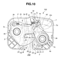
- the rounded lock edge 4f of the lock plate 4 is concentric with the circular opening 4b of the lock plate 4. That is, in the locked condition of the latch plate 3, the rounded lock edge 4f is in contact with a jaw part of the upper finger portion 3d of the latch plate 3 (see Fig. 10 ).
- a holding plate 5 For holding left ends of the latch and lock plate shafts 3a and 4a, there is further provided a holding plate 5 that is postured in parallel with the base plate 2.
- two openings 5b and 5b provided by the holding plate 5 receive therein the left ends of the latch and lock plate shafts 3a and 4a respectively.
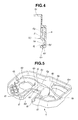
- the opening 5b for the latch plate shaft 3a is depressed toward the base plate 2 to provide a depressed portion 5e, as shown.
- Denoted by reference numeral 5a in Fig. 6 is a straight wall edge possessed by the holding plate 5, which becomes matched with a right wall edge of the striker receiving recess 2a of the base plate 2 when the holding plate 5 is properly mounted to a cover member 6 in an after-mentioned manner. That is, the straight wall edge 5a of the holding plate 5 can reinforce the striker receiving recess 2a of the base plate 2.
- a projection 4c is provided at a diametrically opposed portion of the rounded lock edge 4f with respect to the circular opening 4c.
- annular torsion spring 9 that biases the lock plate 4 to turn in a counterclockwise (or locking) direction to engage the rounded lock edge 4f of the lock plate 4 with the jaw part of the upper finger portion 3d of the latch plate 3.
- the annular torsion spring 9 is disposed around the lock plate shaft 4a between the lock plate 4 and the base plate 2.
- the lock plate 4 is formed with a lever portion 4d near the rounded lock edge 4f, that extends toward the upper finger portion 3d of the latch plate 3.
- the lever portion 4d is used for turning the lock plate 4 in a lock cancelling direction as will be described hereinafter.
- an operation rod that extends from a lock-cancelling knob mounted on an exposed given area of the seat back. That is, upon manipulation of the control knob by an operator (or passenger in the vehicle), the operation rod is moved in a direction to pivot the lock plate 4 in the lock cancelling direction.
- the pressing cam 7 is formed with a circular opening 7b that receives therein the lock plate shaft 4a.
- the pressing cam 7 is formed with a cam surface 7a that can be in contact with the above-mentioned pin 3c of the latch plate 3.
- the pressing cam 7 has near the cam surface 7a a projection 7c for catching one end of a tension spring 8.
- the other end of the tension spring 8 is caught by the above-mentioned spring holding pin 3e. Due to the biasing force of the tension spring 8, the latch plate 3 is biased to turn in a clockwise (or lock cancelling) direction and the pressing cam 7 is biased to turn in a counterclockwise direction.
- the pressing cam 7 is further formed with an engaging arm 7d that projects toward the lock plate 4. That is, when the latch plate 3 becomes unlocked due to turning the lock plate 4 in a clockwise direction, the engaging arm 7d functions to turn the pressing cam 7 in a clockwise direction against the biasing force of the tension spring 8.
- the base plate 2, latch plate 3, lock plate 4, pressing cam 7 and holding plate 5 which are assembled in the above-mentioned manner constitute a thinner mechanism unit as will be understood from Fig. 8 .
- the thinner mechanism unit is neatly received in a cover member 6 that is made of a metal, a plastic or the like. As shown, when the mechanism unit is properly received in the cover member 6, a right major surface of the base plate 2 faces and contacts an inner base surface of the cover member 6.
- the cover member 6 is formed with larger circular openings 6b and 6b for receiving right end portions of the latch and lock plate shafts 3a and 4a.
- the cover member 6 is further formed with a surrounding wall 6c that extends around a periphery of the cover member 6. Furthermore, the cover member 6 is further formed with a generally U-shaped flange (or bridge) 6d at a portion that coincides with the striker receiving recess 2a of the base plate 2.
- an axial length (or height) of the U-shaped flange 6d of the cover member 6 is so set as not to project beyond the striker receiving recess 2a of the base plate 2, as is seen from Fig. 8 .
- the U-shaped flange 6d of the cover member 6 is snugly received in the striker receiving recess 2a of the base plate 2. With this, a naked periphery of the striker receiving recess 2a is covered by the flange 6d of the plastic cover member 6. With this plastic covering, a noise that would be produced when the striker 200 hits against the wall of the striker receiving recess 2a is suppressed or at least damped.
- denoted by reference 6m is an elongate opening formed in the cover member 6, through which the above-mentioned operation rod from the lock-canceling knob passes.
- the cover member 6 is detachably connected to the thinner mechanism by a fixing means which will be described in the following.
- the cover member 6 is formed, at laterally opposed portions of an inner surface of the wall 6c, with respective bosses 6k and 6k each having a sloped top surface, and as is seen from Fig. 6 , the holding plate 5 is formed at its lateral ends with respective arms 5c and 5c each projecting toward the cover member 6 and having an opening 5d.
- the mechanism unit When it is intended to couple the cover member 6 and the mechanism unit, the mechanism unit is pressed against the inner wall of the cover member 6 with a given force. With this pressing action, the two bosses 6k and 6k are pushed into the openings 5d of the arms 5c and 5c in a snap-action manner.
- the following setting means is provided.
- the setting means comprises three pawls 2d, 2d and 2e that are formed by the base plate 2 around the striker receiving recess 2a and depressed toward the cover member 6 and three recesses 6f, 6f and 6g that are formed by the cover member 6 around the U-shaped flange 6d.
- the depressed pawls 2d, 2d and 2e of the base plate 2 are received in the respective recesses 6f, 6f and 6g of the cover member 6 before making axial movement of the base plate 2 relative to the cover member 6.
- the recesses 6f, 6f and 6g of the cover member 6 are formed at their front portions with small projections 6i, 6i and 6j behind which small pockets 6p, 6p, 6p' are formed for receiving the depressed pawls 2d, 2d and 2e.
- Positioning means is further provided for establishing a relative positioning between the cover member 6 and the base plate 2 as will be described in the following.
- the positioning means comprises two openings 2f and 2f (see Figs. 1 and 6 ) that are formed in the base plate 2 at both sides of the striker receiving recess 2a, and two ribs 6h and 6h (see Fig. 5 ) that are formed on the inner wall of the cover member 6 at positions corresponding to those of the two openings 2f and 2f.
- Each rib 6h has a sloped top surface.
- the two ribs 6h and 6h are put into the two openings 2f and 2f to achieve the relative positioning between the cover member 6 and the base plate 2, and thus, positioning of the U-shaped flange 6d of the cover member 6 relative to the striker receiving recess 2a of the base plate 2 is established.
- the lock unit 100 takes an unlock condition as shown in Fig. 9 wherein the latch plate 3 and the lock plate 4 assume their rest positions. That is, under this rest condition, the projection 3p of the latch plate 3 contacts the back edge 4g of the lock plate 4 to place the lock plate 4 at a lock cancelling position. Under this, the latch plate 3 is unlocked.
- the striker receiving recess 2a of the base plate 2 receives the striker 200, as will be understood from Fig. 9 .
- the striker 200 moves into the striker receiving recess 2a and abuts against the upper finger portion 3d of the latch plate 3 and pushes the upper finger portion 3d upward in the drawing against the force of the tension spring 8. Due to insertion of the striker 200 into the striker receiving recess 2a, the latch plate 3 is forced to turn in a counterclockwise direction in Fig. 9 about the latch plate shaft 3a leaving the projection 3p of the latch plate 3 from the back edge 4g of the lock plate 4.
- the lock plate 4 When, as is seen from Fig. 10 , the projection 3p of the latch plate 3 is disengaged from the back edge 4g of the lock plate 4, the lock plate 4 is allowed or forced to turn in a counterclockwise direction about the lock plate shaft 4a due to the biasing force of the annular torsion spring 9, and stopped at an angular position where the rounded lock edge 4f of the lock plate 4 abuts against the jaw part of the upper finger portion 3d of the latch plate 3. Upon this, a clockwise turning of the lock plate 3, which is induced by the biasing force of the torsion spring 8, is blocked by the lock edge 4f of the lock plate 4.
- the latch plate 3 is locked while catching the striker 200 as will be understood from Fig. 10 .
- the striker 200 is locked by the locked latch plate 3.
- the lower finger portion 3h of the latch plate 3 is biased to turn upward in Fig. 10 pressing the striker 200 against the bottom of the striker receiving recess 2a of the base plate 2.
- undesired play of the striker 200 is suppressed.
- undesired play of the lock unit 100 relative to the striker 200 is suppressed or at least minimized.
- the seat back is locked at the predetermined angular position by the lock device.
- a passenger can use the seat as a normal seat having a back rest.
- the turning of the latch plate 3 in the clockwise direction releases the striker 200 from the striker catching recess 3b of the latch plate 3 and at the same time from the striker receiving recess 2a of the base plate 2.
- the lock unit 100 mounted on the seat back is released from the striker 200 fixed to the vehicle body, and thus, the locked condition of the seat back at the predetermined angular position is cancelled. Under this condition, the seat back can be folded up upon receiving a certain handling force.
- the depressed pawls 2d and 2d of the base plate 2 are received in respective pockets 6p and 6p each being defined between a major part of the cover member 6 and the small projection 6i of the cover member 6, and the depressed pawl 2e of the base plate 2 is received in a pocket 6p' defined between the major part of the cover member 6 and the small projection 6j of the cover member 6.
- the ribs 6h and 6h (see Fig. 5 ) of the cover member 6 are snugly received in the openings 2f and 2f (see Figs. 3 and 6 ) of the base plate 2.
- the U-shaped flange 6d of the cover member 6 is disposed on the peripheral edge of the striker receiving recess 2a of the base plate 2 while entirely covering the peripheral edge of the recess 2a, and such disposal is reinforced by the engagement between the depressed pawls 2d, 2d and 2e of the base plate 2 and the pockets 6p, 6p, 6p' provided by the cover member 6. Accordingly, coupling between the base plate 2 and the cover member 6 is tightly achieved.
- the lock unit 100 thus assembled can provide therein a smoothed flat space for neatly housing the latch plate 3 and lock plate 4.
- Figs. 2 to 4 and 8 denoted by reference (b) is an inner surface of the base plate 2.
- the latch plate 3 is placed very close to the inner surface of the base plate 2.
- formation of the smoothed flat space in the lock unit 100 is necessary.
- the latch plate 3 can smoothly rotate about its shaft 3a without being interrupted by the projections 6i, 6i and 6j of the cover member 6, as will be understood from Figs 2 , 3 , 4 and 8 .
- Fig. 8 denoted by reference numeral 10a is one of three projections that are integrally formed on the plastic film 10 that covers the latch plate 3. Due to provision of such projections 10a, the contact resistance between the latch plate 3 and the base plate 2 is reduced.
- the U-shaped flange 6d of the cover member 6 is so sized as not to project beyond the striker receiving recess 2a of the base plate 2, the rotation of the latch plate 3 is smoothly made without being interrupted by the U-shaped flange 6d.
- the base plate 2 is put in the cover member 6, and then the base plate 2 is so postured that the striker receiving recess 2a of the base plate 2 is roughly registered with the U-shaped flange 6d of the cover member 6. Then, the base plate 2 is moved downward in Fig. 6 along an axis of the U-shaped flange 6d for inserting the three depressed pawls 2d, 2d and 2e of the base plate 2 into the respective pockets 6p, 6p and 6p' provided behind the projections 6i, 6i and 6j of the cover member 6, and then, a central area of the base plate 2 is pressed against the inner wall of the cover member 6. Upon this pressing, as will be understood from Fig. 3 and 5 , the two ribs 6h and 6h of the cover member 6 are pressed into the respective openings 2f and 2f of the base plate 2.
- the description is directed to a lock device that is arranged to lock a pivotal seat back to a striker fixed to a vehicle body.
- the lock device can be used for locking a pivotal seat cushion to a striker fixed to a vehicle body.
Landscapes
- Engineering & Computer Science (AREA)
- Aviation & Aerospace Engineering (AREA)
- Transportation (AREA)
- Mechanical Engineering (AREA)
- Lock And Its Accessories (AREA)
- Seats For Vehicles (AREA)
Applications Claiming Priority (1)
| Application Number | Priority Date | Filing Date | Title |
|---|---|---|---|
| JP2012101976A JP5883345B2 (ja) | 2012-04-27 | 2012-04-27 | シートの固定装置 |
Publications (2)
| Publication Number | Publication Date |
|---|---|
| EP2657068A2 true EP2657068A2 (de) | 2013-10-30 |
| EP2657068A3 EP2657068A3 (de) | 2017-11-29 |
Family
ID=48326095
Family Applications (1)
| Application Number | Title | Priority Date | Filing Date |
|---|---|---|---|
| EP13163374.5A Withdrawn EP2657068A3 (de) | 2012-04-27 | 2013-04-11 | Verriegelungsvorrichtung eines Fahrzeugsitzes |
Country Status (4)
| Country | Link |
|---|---|
| US (1) | US8894153B2 (de) |
| EP (1) | EP2657068A3 (de) |
| JP (1) | JP5883345B2 (de) |
| CN (1) | CN103373249B (de) |
Cited By (2)
| Publication number | Priority date | Publication date | Assignee | Title |
|---|---|---|---|---|
| WO2014202468A1 (de) * | 2013-06-18 | 2014-12-24 | Johnson Controls Gmbh | Fahrzeugsitz mit verriegelungseinheit |
| WO2017009336A1 (en) * | 2015-07-14 | 2017-01-19 | Kiekert Ag | Lock for a vehicle seat back |
Families Citing this family (13)
| Publication number | Priority date | Publication date | Assignee | Title |
|---|---|---|---|---|
| CN103597158B (zh) * | 2011-06-17 | 2015-12-23 | 提爱思科技股份有限公司 | 交通工具用锁紧装置 |
| DE102013002820B3 (de) * | 2013-02-15 | 2014-05-28 | Johnson Controls Gmbh | Fahrzeugsitz mit Verriegelungseinheit |
| DE102014200012B4 (de) * | 2013-09-10 | 2025-02-06 | Keiper Seating Mechanisms Co., Ltd. | Verriegelungseinheit für einen Fahrzeugsitz und Fahrzeugsitz |
| JP6364794B2 (ja) * | 2014-01-31 | 2018-08-01 | アイシン精機株式会社 | ロック装置 |
| JP6123718B2 (ja) * | 2014-03-25 | 2017-05-10 | 株式会社アンセイ | シートロック装置 |
| JP2016027968A (ja) * | 2014-07-08 | 2016-02-25 | アイシン精機株式会社 | 車両用シートロック装置 |
| DE102015004282A1 (de) * | 2015-04-08 | 2016-10-13 | Kiekert Aktiengesellschaft | Kraftfahrzeugtürschloss |
| US9914369B2 (en) * | 2015-09-29 | 2018-03-13 | Faurecia Automotive Seating, Llc | Vehicle seat with hook and cam latching mechanism |
| JP6613829B2 (ja) * | 2015-11-09 | 2019-12-04 | アイシン精機株式会社 | シートロック装置 |
| JP6687221B2 (ja) * | 2017-05-30 | 2020-04-22 | 三井金属アクト株式会社 | シートロック装置 |
| JP6691313B2 (ja) | 2018-01-29 | 2020-04-28 | テイ・エス テック株式会社 | ラッチ装置および乗物用シート |
| CZ201937A3 (cs) * | 2019-01-22 | 2020-04-01 | Brano A.S. | Ovládací mechanismus západky zámku |
| EP4243594B1 (de) * | 2020-12-14 | 2025-06-25 | Husqvarna Ab | Aktivierbare tür für ein autonomes gerät |
Citations (3)
| Publication number | Priority date | Publication date | Assignee | Title |
|---|---|---|---|---|
| JPH0296069A (ja) | 1988-10-01 | 1990-04-06 | Mitsui Mining & Smelting Co Ltd | 自動車トランク扉のロック装置 |
| JP2007518000A (ja) | 2004-01-15 | 2007-07-05 | カイペル ゲーエムベーハー アンド カンパニー カーゲー | 車両座席用のロック装置 |
| JP2008265484A (ja) | 2007-04-19 | 2008-11-06 | Toyota Boshoku Corp | ロック装置 |
Family Cites Families (12)
| Publication number | Priority date | Publication date | Assignee | Title |
|---|---|---|---|---|
| JP3609217B2 (ja) * | 1996-09-30 | 2005-01-12 | 株式会社大井製作所 | ロック装置 |
| JP4456339B2 (ja) * | 2003-06-09 | 2010-04-28 | 株式会社大井製作所 | 車両用フードラッチ装置 |
| JP2005132316A (ja) * | 2003-10-31 | 2005-05-26 | T S Tec Kk | 車両用シートのロック装置 |
| US7434862B2 (en) * | 2005-10-11 | 2008-10-14 | Bae Industries, Inc. | Combination front and rear floor latch assembly for selective forward tumbling and removal of a rear row vehicle seat |
| KR100794896B1 (ko) * | 2006-01-23 | 2008-01-14 | 미츠이 긴조쿠 고교 가부시키가이샤 | 차량 시트 잠금장치 |
| JP4688685B2 (ja) * | 2006-01-23 | 2011-05-25 | 三井金属アクト株式会社 | 車両用シートロック装置 |
| DE102007016409B4 (de) * | 2007-03-30 | 2008-12-18 | Keiper Gmbh & Co.Kg | Schloss für einen Fahrzeugsitz |
| JP5056387B2 (ja) * | 2007-12-07 | 2012-10-24 | アイシン精機株式会社 | 車両用ロック装置 |
| JP4625889B2 (ja) * | 2008-07-08 | 2011-02-02 | 三井金属アクト株式会社 | 車両用ラッチ装置 |
| DE102008051832A1 (de) * | 2008-10-17 | 2010-04-22 | Johnson Controls Gmbh | Verriegelungselement für einen Fahrzeugsitz |
| JP5637881B2 (ja) * | 2011-01-31 | 2014-12-10 | 富士機工株式会社 | シートの固定装置 |
| JP5614332B2 (ja) * | 2011-02-28 | 2014-10-29 | アイシン精機株式会社 | 車両用ロック装置 |
-
2012
- 2012-04-27 JP JP2012101976A patent/JP5883345B2/ja active Active
-
2013
- 2013-04-11 EP EP13163374.5A patent/EP2657068A3/de not_active Withdrawn
- 2013-04-26 US US13/871,124 patent/US8894153B2/en not_active Expired - Fee Related
- 2013-04-26 CN CN201310149257.9A patent/CN103373249B/zh not_active Expired - Fee Related
Patent Citations (3)
| Publication number | Priority date | Publication date | Assignee | Title |
|---|---|---|---|---|
| JPH0296069A (ja) | 1988-10-01 | 1990-04-06 | Mitsui Mining & Smelting Co Ltd | 自動車トランク扉のロック装置 |
| JP2007518000A (ja) | 2004-01-15 | 2007-07-05 | カイペル ゲーエムベーハー アンド カンパニー カーゲー | 車両座席用のロック装置 |
| JP2008265484A (ja) | 2007-04-19 | 2008-11-06 | Toyota Boshoku Corp | ロック装置 |
Cited By (2)
| Publication number | Priority date | Publication date | Assignee | Title |
|---|---|---|---|---|
| WO2014202468A1 (de) * | 2013-06-18 | 2014-12-24 | Johnson Controls Gmbh | Fahrzeugsitz mit verriegelungseinheit |
| WO2017009336A1 (en) * | 2015-07-14 | 2017-01-19 | Kiekert Ag | Lock for a vehicle seat back |
Also Published As
| Publication number | Publication date |
|---|---|
| JP2013226992A (ja) | 2013-11-07 |
| EP2657068A3 (de) | 2017-11-29 |
| CN103373249A (zh) | 2013-10-30 |
| JP5883345B2 (ja) | 2016-03-15 |
| US8894153B2 (en) | 2014-11-25 |
| CN103373249B (zh) | 2015-09-30 |
| US20130285429A1 (en) | 2013-10-31 |
Similar Documents
| Publication | Publication Date | Title |
|---|---|---|
| EP2657068A2 (de) | Verriegelungsvorrichtung eines Fahrzeugsitzes | |
| EP2657067B1 (de) | Verriegelungsvorrichtung eines Fahrzeugsitzes | |
| JPH077225Y2 (ja) | 車載移動体の閉位置係止装置 | |
| US7226096B2 (en) | Door handle device for vehicles | |
| US9994129B1 (en) | Seatback latch | |
| JP7192426B2 (ja) | 車両用ドアロック装置 | |
| JP7000736B2 (ja) | 車両用ハンドル装置 | |
| EP0123251B1 (de) | Türverschluss | |
| JP3444721B2 (ja) | 自動車用ドアハンドル | |
| JPH0550875A (ja) | 自動車のコンソールボツクス | |
| JP4939253B2 (ja) | リッド開放操作装置 | |
| JPH0111894Y2 (de) | ||
| JP2000213220A (ja) | 車載用収納箱 | |
| JPH08333936A (ja) | チャイルドレバーを備えた自動車用ドアロック装置 | |
| JP3683465B2 (ja) | ロック装置 | |
| KR100600649B1 (ko) | 자동차의 후드 개방장치 | |
| US11773632B2 (en) | Vehicular door outer handle device | |
| JPH0223719Y2 (de) | ||
| JP2527580Y2 (ja) | 自動車用ドアロック装置 | |
| JPH0225704Y2 (de) | ||
| JP2001020583A (ja) | ハンドル装置 | |
| JP3138204B2 (ja) | シフトレバー装置用シフトロック解除ボタン | |
| JPH048208Y2 (de) | ||
| JP4335552B2 (ja) | ロック装置 | |
| JPH0336679Y2 (de) |
Legal Events
| Date | Code | Title | Description |
|---|---|---|---|
| PUAI | Public reference made under article 153(3) epc to a published international application that has entered the european phase |
Free format text: ORIGINAL CODE: 0009012 |
|
| AK | Designated contracting states |
Kind code of ref document: A2 Designated state(s): AL AT BE BG CH CY CZ DE DK EE ES FI FR GB GR HR HU IE IS IT LI LT LU LV MC MK MT NL NO PL PT RO RS SE SI SK SM TR |
|
| AX | Request for extension of the european patent |
Extension state: BA ME |
|
| PUAL | Search report despatched |
Free format text: ORIGINAL CODE: 0009013 |
|
| AK | Designated contracting states |
Kind code of ref document: A3 Designated state(s): AL AT BE BG CH CY CZ DE DK EE ES FI FR GB GR HR HU IE IS IT LI LT LU LV MC MK MT NL NO PL PT RO RS SE SI SK SM TR |
|
| AX | Request for extension of the european patent |
Extension state: BA ME |
|
| RIC1 | Information provided on ipc code assigned before grant |
Ipc: B60N 2/015 20060101AFI20171023BHEP Ipc: B60N 2/36 20060101ALI20171023BHEP |
|
| RAP1 | Party data changed (applicant data changed or rights of an application transferred) |
Owner name: TF-METAL CO., LTD. |
|
| STAA | Information on the status of an ep patent application or granted ep patent |
Free format text: STATUS: THE APPLICATION IS DEEMED TO BE WITHDRAWN |
|
| 18D | Application deemed to be withdrawn |
Effective date: 20180530 |