EP2657080A2 - Unterscheinwerfereinheit und Unterscheinwerfersystem zur Verwendung in einem Fahrzeug, das sich in Kurven lehnt, sowie Fahrzeug, das sich in Kurven lehnt - Google Patents
Unterscheinwerfereinheit und Unterscheinwerfersystem zur Verwendung in einem Fahrzeug, das sich in Kurven lehnt, sowie Fahrzeug, das sich in Kurven lehnt Download PDFInfo
- Publication number
- EP2657080A2 EP2657080A2 EP13164320.7A EP13164320A EP2657080A2 EP 2657080 A2 EP2657080 A2 EP 2657080A2 EP 13164320 A EP13164320 A EP 13164320A EP 2657080 A2 EP2657080 A2 EP 2657080A2
- Authority
- EP
- European Patent Office
- Prior art keywords
- sub headlight
- light source
- headlight light
- vehicle
- lean angle
- Prior art date
- Legal status (The legal status is an assumption and is not a legal conclusion. Google has not performed a legal analysis and makes no representation as to the accuracy of the status listed.)
- Granted
Links
Images






Classifications
-
- B—PERFORMING OPERATIONS; TRANSPORTING
- B60—VEHICLES IN GENERAL
- B60Q—ARRANGEMENT OF SIGNALLING OR LIGHTING DEVICES, THE MOUNTING OR SUPPORTING THEREOF OR CIRCUITS THEREFOR, FOR VEHICLES IN GENERAL
- B60Q1/00—Arrangement of optical signalling or lighting devices, the mounting or supporting thereof or circuits therefor
- B60Q1/02—Arrangement of optical signalling or lighting devices, the mounting or supporting thereof or circuits therefor the devices being primarily intended to illuminate the way ahead or to illuminate other areas of way or environments
- B60Q1/04—Arrangement of optical signalling or lighting devices, the mounting or supporting thereof or circuits therefor the devices being primarily intended to illuminate the way ahead or to illuminate other areas of way or environments the devices being headlights
- B60Q1/06—Arrangement of optical signalling or lighting devices, the mounting or supporting thereof or circuits therefor the devices being primarily intended to illuminate the way ahead or to illuminate other areas of way or environments the devices being headlights adjustable, e.g. remotely-controlled from inside vehicle
- B60Q1/08—Arrangement of optical signalling or lighting devices, the mounting or supporting thereof or circuits therefor the devices being primarily intended to illuminate the way ahead or to illuminate other areas of way or environments the devices being headlights adjustable, e.g. remotely-controlled from inside vehicle automatically
- B60Q1/12—Arrangement of optical signalling or lighting devices, the mounting or supporting thereof or circuits therefor the devices being primarily intended to illuminate the way ahead or to illuminate other areas of way or environments the devices being headlights adjustable, e.g. remotely-controlled from inside vehicle automatically due to steering position
-
- B—PERFORMING OPERATIONS; TRANSPORTING
- B60—VEHICLES IN GENERAL
- B60Q—ARRANGEMENT OF SIGNALLING OR LIGHTING DEVICES, THE MOUNTING OR SUPPORTING THEREOF OR CIRCUITS THEREFOR, FOR VEHICLES IN GENERAL
- B60Q1/00—Arrangement of optical signalling or lighting devices, the mounting or supporting thereof or circuits therefor
- B60Q1/02—Arrangement of optical signalling or lighting devices, the mounting or supporting thereof or circuits therefor the devices being primarily intended to illuminate the way ahead or to illuminate other areas of way or environments
- B60Q1/04—Arrangement of optical signalling or lighting devices, the mounting or supporting thereof or circuits therefor the devices being primarily intended to illuminate the way ahead or to illuminate other areas of way or environments the devices being headlights
- B60Q1/18—Arrangement of optical signalling or lighting devices, the mounting or supporting thereof or circuits therefor the devices being primarily intended to illuminate the way ahead or to illuminate other areas of way or environments the devices being headlights being additional front lights
-
- B—PERFORMING OPERATIONS; TRANSPORTING
- B62—LAND VEHICLES FOR TRAVELLING OTHERWISE THAN ON RAILS
- B62J—CYCLE SADDLES OR SEATS; AUXILIARY DEVICES OR ACCESSORIES SPECIALLY ADAPTED TO CYCLES AND NOT OTHERWISE PROVIDED FOR, e.g. ARTICLE CARRIERS OR CYCLE PROTECTORS
- B62J6/00—Arrangement of optical signalling or lighting devices on cycles; Mounting or supporting thereof; Circuits therefor
- B62J6/02—Headlights
- B62J6/022—Headlights specially adapted for motorcycles or the like
- B62J6/023—Headlights specially adapted for motorcycles or the like responsive to the lean angle of the cycle, e.g. changing intensity or switching sub-lights when cornering
-
- B—PERFORMING OPERATIONS; TRANSPORTING
- B62—LAND VEHICLES FOR TRAVELLING OTHERWISE THAN ON RAILS
- B62J—CYCLE SADDLES OR SEATS; AUXILIARY DEVICES OR ACCESSORIES SPECIALLY ADAPTED TO CYCLES AND NOT OTHERWISE PROVIDED FOR, e.g. ARTICLE CARRIERS OR CYCLE PROTECTORS
- B62J6/00—Arrangement of optical signalling or lighting devices on cycles; Mounting or supporting thereof; Circuits therefor
- B62J6/05—Direction indicators
- B62J6/055—Electrical means, e.g. lamps
-
- B—PERFORMING OPERATIONS; TRANSPORTING
- B60—VEHICLES IN GENERAL
- B60Q—ARRANGEMENT OF SIGNALLING OR LIGHTING DEVICES, THE MOUNTING OR SUPPORTING THEREOF OR CIRCUITS THEREFOR, FOR VEHICLES IN GENERAL
- B60Q2300/00—Indexing codes for automatically adjustable headlamps or automatically dimmable headlamps
- B60Q2300/05—Special features for controlling or switching of the light beam
- B60Q2300/054—Variable non-standard intensity, i.e. emission of various beam intensities different from standard intensities, e.g. continuous or stepped transitions of intensity
-
- B—PERFORMING OPERATIONS; TRANSPORTING
- B60—VEHICLES IN GENERAL
- B60Q—ARRANGEMENT OF SIGNALLING OR LIGHTING DEVICES, THE MOUNTING OR SUPPORTING THEREOF OR CIRCUITS THEREFOR, FOR VEHICLES IN GENERAL
- B60Q2300/00—Indexing codes for automatically adjustable headlamps or automatically dimmable headlamps
- B60Q2300/10—Indexing codes relating to particular vehicle conditions
- B60Q2300/13—Attitude of the vehicle body
- B60Q2300/136—Roll
Definitions
- the present invention relates to a sub headlight unit and a sub headlight system for use in a vehicle that leans into turns, and to a vehicle that leans into turns.
- a rider In general, in a vehicle that leans into turns (such as saddle-ride type vehicles including motorcycles, three-wheeled motor vehicles, snowmobiles, and ATVs (all terrain vehicles)), when the vehicle corners or turns at an intersection, a rider operates a handlebar and additionally shifts his/her own weight in order to counteract centrifugal force acting on a vehicle body. Thereby, the vehicle turns with an attitude (hereinafter, also referred to as "lean attitude") leaning to the inner side of a curve.
- a rider operatics a steering wheel and turns with centrifugal force acting on a vehicle body. Therefore, in the vehicle that does not lean into turns, the vehicle body leans to the outer side of a curve due to the centrifugal force.
- the turning is made with an active use of the weight shifting of the rider himself/herself. Therefore, the vehicle body largely leans.
- the vehicle body leans to the outer of the curve due to the centrifugal force. The of this leaning varies depending on the running speed of the vehicle and the magnitude (radius) of the curve, and this of the vehicle body is not utilized for the turning. In the vehicle that does not lean into turns, it is preferable that the of leaning to the outer side of the curve due to the centrifugal force is small.
- the vehicle that leans into turns causes the vehicle body to lean to the inner side of the curve with a relatively large of leaning, while the vehicle that does not lean into turns causes the vehicle body to lean to the outer side of the curve with a relatively small amount of leaning.
- a vehicle is provided with a plurality of lights irrespective of whether or not the vehicle leans into turns.
- the lights include a light intended mainly to ensure a field of view of a rider of the vehicle and a light intended mainly to enable a surrounding vehicle or the like to recognize the presence of the own vehicle.
- a headlight is the light intended mainly to ensure the field of view of the rider of the vehicle, and in general, is configured to switch between a high beam (running headlight) and a low beam (passing headlight).
- the high beam which emits light in a horizontal (upward) direction, ensures a field of view at a long distance.
- the high beam is used in a situation where there is no vehicle or the like existing ahead at night.
- the low beam which emits light in a downward direction, is used even in a situation where there is a vehicle or the like existing ahead. Therefore, in a normal case, a vehicle often runs with the low beam turned on.
- an illumination range of a headlight light source spreads evenly to the left and right in an area ahead in an advancing direction and below a horizontal plane including the headlight light source.
- the vehicle that leans into turns is running on a road curving to the left, the vehicle runs with the vehicle body inclined to the left. Accordingly, the illumination range of the headlight light source spreads downward to the left. As a result, a nearer position on a running lane is illuminated. Thus, the illumination range in an area inside the curve and ahead in the advancing direction is reduced.
- a vehicle in which, in addition to a main headlight that illuminates an area ahead of the vehicle, a pair of right and left sub headlights that are turned on depending on the magnitude of a lean angle (angle of inclination of a vehicle body to the inner side of a curve relative to an upright state thereof) are provided as the headlight ( WO 2010/061651 ).
- Each of the sub headlights includes two light sources (filaments).
- the lean angle increases and reaches a predetermined value
- one of the two light sources included in the sub headlight is turned on.
- the lean angle further increases and reaches a predetermined value
- the two light sources are turned on.
- Such a vehicle is known from WO 2010/061651 .
- the lean angle is gently changed in a curve with a large radius while the lean angle is rapidly changed in a curve with a small radius. Accordingly, for example, in a case of continuously passing through a plurality of curves having different radii during touring on a mountain road, the amount of change in the lean angle per unit time changes in each curve, even though the speed does not change so much.
- the two light sources of the sub headlight are sequentially turned on in accordance with an increase in the lean angle. Accordingly, at a time point when a light source is turned on, an illumination range of this light source is additionally provided, which can suppress a reduction in the illumination range which may be caused by inclination of the vehicle.
- an illumination range of a sub headlight produced on a road surface continuously approaches to the vehicle, and accordingly a cut-off line of the sub headlight also approaches to the vehicle.
- the speed of movement of the cut-off line of the sub headlight light source varies depending on the amount of change in the lean angle per unit time.
- the speed of movement of the cut-off line varies depending on a running scene. Therefore, in a case where the speed of movement of the cut-off line largely changes upon each turn in a curve or in a case where the speed of movement of the cut-off line increases, the rider may feel uncomfortable.
- the present invention has been made in view of the problems described above, and an object of the present invention is to prevent a rider from feeling uncomfortable about a change in an illumination range in the course of an increase or decrease in the lean angle of a vehicle body.
- the present invention adopts the following configurations.
- a main headlight light source or a sub headlight light source included in the vehicle has been already turned on
- a first headlight light source included in the vehicle
- an illumination range produced on a road surface is reduced so that a cut-off line of the first headlight light source that has been already turned on approaches to the vehicle. Therefore, the illumination range of the first headlight light source gradually moves away from a position a rider desires to see toward the vehicle.
- the second sub headlight light source lights up with a brightness lower than the first brightness.
- an illumination range of the second sub headlight light source that is currently turned on partially overlaps the cut-off line of the first headlight light source that has been previously turned on.
- the brightness of the second sub headlight light source is lower than the first brightness. Therefore, a situation where the turn-on of the second sub headlight makes the rider feel uncomfortable is suppressed.
- the illumination range of the first headlight light source is reduced so that the cut-off line approaches to the vehicle, and when the lean angle reaches the reference value that is set for the second headlight light source, the second headlight light source lights up with the first brightness. Accordingly, when the illumination range of the first headlight light source is moving away from the position the rider desires to see, the illumination range of the second headlight light source can spread over the position the rider desires to see. As a result, the cut-off line of the second headlight light source is more conspicuous to the rider than the cut-off line of the first headlight light source.
- An illumination range having a predetermined illuminance is enlarged along with an increase in the brightness of the second headlight light source from the brightness lower than the first brightness to the first brightness. Therefore, an effect of reducing the speed of approach of the cut-off line to the vehicle is exerted. Since the effect of reducing the speed of movement of the cut-off line is exerted, a change in the speed of movement of the cut-off line which occurs in each turn can be made small. This enables suppression of an uncomfortable feeling, which may otherwise be given to the rider. Since a reduction in the illumination range of the headlight is suppressed, occurrence of a situation where the position the rider desires to see is not sufficiently covered by the illumination range of the headlight can be suppressed. This enables suppression of an uncomfortable feeling, which may otherwise be given to the rider.
- the brightness of the headlight light source changes in accordance with the lean angle of the vehicle.
- the illumination range of the sub headlight light source is located in a space below the horizontal line. Accordingly, occurrence of glare can be suppressed.
- the illumination range of the sub headlight light source contains a space above the horizontal line. However, the sub headlight light source lights up with a brightness lower than the first brightness, and therefore occurrence of glare can be suppressed.
- the cut-off line of the sub headlight light source is close to horizontal. Accordingly, when the headlight light source lights up with the first brightness, a wide illumination range can be ensured on a road surface, with prevention of glare.
- the sub headlight light sources along with an increase in the lean angle, the sub headlight light sources, sequentially from the one having the smallest reference value set therefor, lights up with the brightness lower than the first brightness and then lights up with the first brightness. Sequentially changing the brightness of each sub headlight light source in this manner can slow the speed of movement of the cut-off line while suppressing a reduction in the illumination range of the sub headlight light source in accordance with the increase in the lean angle.
- the second headlight light source lights up with a brightness lower than the first brightness before the first headlight light source lights up with the first brightness, it is difficult to fully enjoy the advantage of compensation of the illumination range by the second headlight light source, because the brightness of the first headlight light source will be subsequently increased. Therefore, in a configuration of (5), in the course of an increase in the lean angle, the second headlight light source is caused to light up with a brightness lower than the first brightness after the first headlight light source lights up with the first brightness.
- the first headlight light source means such a headlight light source that the reference value of the lean angle set therefor is the first to be reached in the course of the lean angle increasing and reaching the reference value of the headlight light source.
- the second headlight light source means such a headlight light source that the reference value of the lean angle set therefor is the next to be reached after the reference value of the first headlight light source is reached.
- an AFS Adaptive Front-Lighting System
- a configuration of (8) can suppress a change in the illumination range of the sub headlight light source which is caused by a variation in the supply voltage supplied from the battery to the sub headlight light source. Accordingly, occurrence of glare can be suppressed.
- the present invention can also adopt the following configurations.
- a configuration of (8-1) can correct a reduction in the brightness of the sub headlight light source (for example, an LED) caused by a temperature rise.
- the sub headlight light source for example, an LED
- a configuration of (8-2) or (8-3) can correct a reduction in the brightness of the sub headlight light source caused by a long-term use.
- the configuration of (9) is also adoptable in the sub headlight system according to any one of (8-1) to (8-3) described above.
- a configuration of (10) enables suppression of occurrence of a situation where the rider feels uncomfortable about a change in the illumination range.
- the optical axis is a straight line that passes through a light source and the center of a maximum illuminance portion of emitted light.
- the center of the maximum illuminance portion of the emitted light can be identified by emitting light from a light source to a screen that is placed ahead of the light source.
- This screen illuminance test can be implemented by a method specified in JIS D1619.
- the cut-off line and the illumination range having the predetermined illuminance can be identified based on a result (such as an isolux distribution map) of the screen illuminance test mentioned above.
- the illumination range means an illumination range having a predetermined illuminance, and this predetermined illuminance is not particularly limited.
- the cut-off line and the illumination range having the predetermined illuminance in a plan view can be identified based on a road-surface light distribution that is obtained by converting the result of the screen illuminance test mentioned above into the road-surface light distribution.
- the conversion into the road-surface light distribution can be implemented by a conventionally known method.
- conversion from a screen illuminance value into a road-surface illuminance value can be performed.
- the following expression (I) is usable.
- D represents a light source
- E represents a point on a road surface
- F represents a point of intersection at which the screen placed between D and E intersects with a straight line connecting D to E.
- Road - surface illuminance Lx Screen Illuminance Lx ⁇ Distance between D and F m / Distance between D and E m 2
- the present invention enables suppression of occurrence of a situation where a rider feels uncomfortable about a change in an illumination range.
- FIG. 1 is a front elevational view schematically showing a motorcycle according to a first embodiment of the present invention.
- a motorcycle 10 is an example of a vehicle that leans into turns according to the present invention.
- vehicle that leans into turns For example, saddle-ride type vehicles including motorcycles, three-wheeled motor vehicles, snowmobiles, and ATVs (all terrain vehicles) may be mentioned.
- front and back are terms with respect to an advancing direction of the vehicle
- the terms “up” and “down” are terms with respect to the vertical direction of the vehicle
- the terms “right” and “left” are terms with respect to a rider.
- the motorcycle 10 includes a handlebar 12.
- An operation switch 15 is provided in a left portion of the handlebar 12 with respect to a width direction of the vehicle.
- the operation switch 15 includes a beam switch 15B and a flasher switch 15F (see FIG. 2 ).
- a steering shaft (not shown) is fixed to a center portion of the handlebar 12 with respect to the width direction of the vehicle.
- the steering shaft extends downward through a headpipe (not shown).
- a frontfork 17 is provided at a lower end of the steering shaft.
- a front wheel 16 is rotatably supported at the lower end of the frontfork 17.
- the headpipe is a member constituting a vehicle body frame. In the present invention, no particular limitation is put on the vehicle body frame, and a conventionally known configuration is adoptable.
- a front cover 18 covers a front part of the headpipe having the steering shaft passing therethrough.
- a main headlight 11 is provided in a center portion with respect to the width direction of the vehicle.
- the main headlight 11 includes a high beam light source 11 H (running headlight) and a low beam light source 11L (passing headlight).
- the high beam light source 11H illuminates an area ahead of the motorcycle 10 at a height equal to or above a horizontal plane of the main headlight 11.
- the low beam light source 11L illuminates an area ahead of the motorcycle 10 at a height below the horizontal plane of the main headlight 11.
- the high beam light source 11H and the low beam light source 11L are configured such that only one of them is turned on in accordance with an operation performed on the beam switch 15B (see FIG. 2 ) by the rider.
- the motorcycle 10 includes a sub headlight 13.
- the sub headlight 13 is composed of two sub headlight units 13L and 13R of variable light distribution type. Each of the sub headlight units 13L and 13R is provided at each side with respect to the width direction of the vehicle.
- the sub headlight unit 13L includes a plurality of sub headlight light sources 13La, 13Lb, and 13Lc.
- the sub headlight light sources 13La, 13Lb, and 13Lc are arranged in this order from the center toward the upper left with respect to the width direction of the vehicle.
- the sub headlight light sources 13La, 13Lb, and 13Lc illuminate an area ahead and left-lateral with respect to the width direction of the vehicle.
- Illumination ranges of the sub headlight light sources 13La, 13Lb, and 13Lc are arranged in this order from the center toward the upper left with respect to the width direction of the vehicle.
- the illumination ranges of the sub headlight light sources 13La, 13Lb, and 13Lc overlap one another.
- the sub headlight unit 13R includes a plurality of sub headlight light sources 13Ra, 13Rb, and 13Rc.
- the sub headlight light sources 13Ra, 13Rb, and 13Rc are arranged in this order from the center toward the upper right with respect to the width direction of the vehicle.
- the sub headlight light sources 13Ra, 13Rb, and 13Rc illuminate an area ahead and right-lateral with respect to the width direction of the vehicle.
- Illumination ranges of the sub headlight light sources 13Ra, 13Rb, and 13Rc are arranged in this order from the center toward the upper right with respect to the width direction of the vehicle.
- the illumination ranges of the sub headlight light sources 13Ra, 13Rb, and 13Rc overlap one another.
- Optical axes of the sub headlight light sources 13La to 13Lc, 13Ra to 13Rc are fixed, and not moved in accordance with a lean angle.
- a reflector (not shown) of the sub headlight light source is also fixed, and not moved in accordance with the lean angle.
- no particular limitation is put on the sub headlight light source.
- an LED is adoptable.
- a mono-focus type light source is also adoptable as the sub headlight light source.
- the above-described arrangement manner is merely an illustrative example of the present invention. The present invention is not limited to this example.
- Flashers 14L and 14R serving as direction indicators, are provided at both sides of the motorcycle 10 with respect to the width direction of the vehicle.
- the flashers 14L and 14R are configured such that only one of them is turned on in accordance with an operation performed on the flasher switch 15F (see FIG. 2 ) by the rider.
- the plurality of sub headlight light sources 13La, 13Lb, and 13Lc which are positioned at the left side in the motorcycle 10 with respect to the width direction of the vehicle, are arranged between the main headlight 11 and the flasher 14L.
- no particular limitation is put on the positional relationship between the sub headlight light source and the flasher with respect to the width direction of the vehicle.
- the sub headlight light source is provided outside the flasher with respect to the width direction of the vehicle.
- the plurality of sub headlight light sources 13La, 13Lb, and 13Lc are provided above the main headlight 11 and the flasher 14L.
- the plurality of sub headlight light sources 13Ra, 13Rb, and 13Rc are provided above the main headlight 11 and the flasher 14R.
- the plurality of sub headlight light sources 13La to 13Lc which are provided to the left with respect to the width direction of the vehicle, illuminate an area ahead of and left-lateral to the motorcycle 10.
- the plurality of sub headlight light sources 13Ra to 13Rc which are provided to the right with respect to the width direction of the vehicle, illuminate an area ahead of and right-lateral to the motorcycle 10.
- FIG. 2 is a block diagram showing a basic configuration concerning the sub headlight light sources 13La to 13Lc, 13Ra to 13Rc of the motorcycle 10 shown in FIG. 1 .
- the operation switch 15 includes the beam switch 15B and the flasher switch 15F.
- the beam switch 15B is connected to the high beam light source 11H and the low beam light source 11L included in the main headlight 11.
- turn-on/turn-off of the high beam light source 11H and the low beam light source 11L is switched in accordance with the operation performed on the beam switch 15B.
- the flasher switch 15F is connected to the flashers 14L and 14R.
- the rider operates the flasher switch 15F, one of the flashers 14L and 14R is caused to flash in accordance with the operation performed on the flasher switch 15F.
- the lean angle sensor 22 is a gyro sensor that detects the angular velocity about an axis in the front-back direction of the motorcycle 10.
- the lean angle sensor 22 supplies, to a controller 20, a signal indicating the detected angular velocity (roll rate) about the axis in the front-back direction.
- the vehicle speed sensor 23 detects the vehicle speed, and supplies, to the controller 20, a signal indicating the detected vehicle speed.
- the controller 20 calculates the lean angle of the motorcycle 10 based on the angular velocity about the axis in the front-back direction and the vehicle speed.
- the roll rate is integrated over time, and the vehicle speed is used as correction information, thereby calculating the lean angle.
- a method for calculating the lean angle is not limited to this example.
- the vehicle speed is not an essential variable.
- a conventionally known method is adoptable.
- the calculation may be performed based on a static equilibrium equation by using the yaw rate (angular velocity about an axis in the vertical direction) and the vehicle speed.
- the correction information is not limited to the vehicle speed. For example, it may be acceptable to provide a plurality of gyro sensors and G sensors and use values obtained from these sensors and the vehicle speed as the correction information.
- GPS position information and/or geomagnetic information may be used as the correction information.
- sensors detection part
- An appropriate sensor may be provided in accordance with variables available for the calculation.
- the controller 20 includes a memory (not shown).
- the memory stores, in the form of data, a plurality of reference values K(°) to be compared with the lean angle.
- the memory stores three reference values (a first reference value K 1 , a second reference value K 2 , and a third reference value K 3 ).
- the first reference value K 1 , the second reference value K 2 , and the third reference value K 3 satisfy the relationship of "first reference value K 1 ⁇ second reference value K 2 ⁇ third reference value K 3 ".
- the memory stores, in the form of data, lower values T(°) to be compared with the lean angle.
- the lower value corresponds to the lean angle obtained when a light source that has been turned off is starting to light up in the course of an increase in the lean angle.
- the memory stores three lower values (a first lower value T 1 , a second lower value T 2 , and a third lower value T 3 ).
- the first lower value T 1 , the second lower value T 2 , and the third lower value T 3 satisfy the relationship of "first lower value T 1 ⁇ second lower value T 2 ⁇ third lower value T 3 ".
- Each of the lower values T is smaller than each corresponding reference value K. To be specific, the relationship of "first lower value T 1 ⁇ first reference value K 1 " is satisfied.
- the memory stores, in the form of data, upper values U(°) to be compared with the lean angle.
- the upper value corresponds to the lean angle obtained when a light source is starting to light up with the highest brightness in the course of an increase in the lean angle.
- the memory stores three upper values (a first upper value U 1 , a second upper value U 2 , and a third upper value U 3 ).
- the first upper value U 1 , the second upper value U 2 , and the third upper value U 3 satisfy the relationship of "first upper value U 1 ⁇ second upper value U 2 ⁇ third upper value U 3 ".
- Each of the upper values U is greater than each corresponding reference value K. To be specific, the relationship of "first reference value K 1 ⁇ first upper value U 1 " is satisfied.
- the memory stores, in the form of data, specific values I(°) to be compared with the lean angle.
- the specific value corresponds to the lean angle obtained when a light source that has lighted up with the highest brightness is starting to dim in the course of an increase in the lean angle.
- the memory stores two specific values (a first specific value I 1 and a second specific value I 2 ).
- the first specific value I 1 and the second specific value I 2 satisfy the relationship of "first specific value I 1 ⁇ second specific value I 2 ".
- Each of the specific values I is greater than each corresponding upper value U. To be specific, the relationship of "first upper value U 1 ⁇ first specific value I 1 " is satisfied.
- the memory stores, in the form of data, defined values J(°) to be compared with the lean angle.
- the defined value corresponds to the lean angle obtained when the lowest brightness is achieved in the course of an increase in the lean angle beyond the specific value. While the lean angle is equal to or greater than the defined value, the state (brightness) obtained when the lean angle takes the defined value is maintained.
- the memory stores two defined values (a first defined value J 1 and a second defined value J 2 ).
- the first defined value J 1 and the second defined value J 2 satisfy the relationship of "first defined value J 1 ⁇ second defined value J 2 ".
- Each of the defined values J is greater than each corresponding specific value I. To be specific, the relationship of "first specific value I 1 ⁇ first defined value J 1 " is satisfied.
- the first reference value K 1 , the first lower value T 1 , the first upper value U 1 , the first specific value I 1 , and the first defined value J 1 are associated with the sub headlight light sources 13La and 13Ra.
- the second reference value K 2 , the second lower value T 2 , the second upper value U 2 , the second specific value I 2 , and the second defined value J 2 are associated with the sub headlight light sources 13Lb and 13Rb.
- the third reference value K 3 , the third lower value T 3 , and the third upper value U 3 are associated with the sub headlight light sources 13Lc and 13Rc.
- the sub headlight light sources 13Lc and 13Rc, with which the greatest reference value is associated have no specific value and no defined value associated therewith. The relationship between each variable and the brightness of the sub headlight light source will be detailed later with reference to FIG. 4 .
- An answerback main unit 21 is connected to the controller 20.
- the answerback main unit 21 receives a signal radio wave from a remote control key 25.
- the sub headlight light sources 13La to 13Lc, 13Ra to 13Rc are connected to the controller 20.
- a power source 26 (battery) is connected to the high beam light source 11H and the low beam light source 11 L via the beam switch 15B.
- the power source 26 is connected to the flashers 14L and 14R via the flasher switch 15F.
- the power source 26 is connected to the controller 20.
- the controller 20 controls the brightnesses of the sub headlight light sources 13La to 13Lc, 13Ra to 13Rc.
- the sub headlight light sources 13La to 13Lc, 13Ra to 13Rc are configured of LEDs.
- the controller 20 performs a pulse width modulation control (PWM control) to adjust the duty cycle, and thereby the brightnesses are controlled (dimming control).
- PWM control pulse width modulation control
- a method for performing the dimming control on the sub headlight light source is not particularly limited. For example, it may be conceivable to control a current to be supplied to the sub headlight light source, or to control a voltage to be supplied to the sub headlight light source.
- a single sub headlight light source may include a plurality of light sources having different brightnesses.
- the dimming control on the sub headlight light source can be implemented by switching which of the light sources is turned on.
- the brightness of the light source can be controlled by switching the turned-on light source from the light source configured to light up with a first brightness to the light source configured to light up with a second brightness.
- a single sub headlight light source may include a plurality of light sources.
- the dimming control on the sub headlight light source can be implemented by changing the number or combination of light sources that are turned on.
- the brightnesses of the plurality of light sources may be either different or the same.
- a single sub headlight light source includes a plurality of light sources (for example, four light sources) having the same brightness, turning on part of the plurality of light sources enables the sub headlight light source to light up with the first brightness, while turning on all the plurality of light sources enables the sub headlight light source to light up with the second brightness.
- a voltage detector (not shown) for detecting a supply voltage that is supplied from the power source 26 to each of the sub headlight light sources 13La to 13Lc, 13Ra to 13Rc may be provided in a cable that connects the controller 20 to each of the sub headlight light sources 13La to 13Lc, 13Ra to 13Rc.
- a supply voltage value detected by the voltage detector is, in the form of data, supplied to the controller 20 at a predetermined timing, for example. In this case, data indicating a reference voltage value of the power source 26 is stored in the memory of the controller 20.
- the controller 20 performs an information acquisition process for acquiring data indicating the supply voltage value from the voltage detector, and compares the supply voltage value against the reference voltage value, to calculate a difference between the supply voltage value and the reference voltage value.
- the memory of the controller 20 stores a data table indicating a correspondence relationship of the rate of correction of the brightness of the sub headlight light source relative to the difference between the supply voltage value and the reference voltage value. In this data table, as the absolute value of the difference between the supply voltage value and the reference voltage value increases, the absolute value of the rate of correction of the brightness of the sub headlight light source increases. When a difference of the supply voltage value from the reference voltage value is a positive value, the rate of correction is set to be a negative value.
- a correction object to be corrected is not particularly limited. At least one of a voltage value, a current value, and a duty cycle value may be adopted as the correction object. It may be also acceptable that the memory stores a table associating the supply voltage value with the rate of correction of the brightness of the sub headlight light source. In this table data, the rate of correction is set based on the reference voltage value.
- the controller 20 does not have to calculate the difference of the supply voltage value from the reference voltage value. In this case, an indirect comparison between the supply voltage value and the reference voltage value is performed. Furthermore, although the above-described example describes a case where the memory includes the data table, the rate of correction may be calculated through computing with use of the supply voltage value or with use of the difference of the supply voltage value from the reference voltage value. Then, based on the rate of correction thus obtained, the value of the correction object (such as the voltage, the current, the duty cycle) is corrected.
- the rate of correction object such as the voltage, the current, the duty cycle
- the controller 20 controls the supply voltage supplied to each of the sub headlight light sources 13La to 13Lc, so that the supply voltage supplied from the controller 20 to each of the sub headlight light sources 13La to 13Lc, 13Ra to 13Rc is made constant.
- the brightness of each of the sub headlight light sources 13La to 13Lc, 13Ra to 13Rc can be controlled by adjusting the current value or the duty cycle.
- the above-described brightness control (adjustment process) is performed on the sub headlight light sources 13La to 13Lc, 13Ra to 13Rc, while when the lean angle is out of this range, the brightness control is not performed. Accordingly, at a time of causing the sub headlight light source to light up with a high brightness, an output of the sub headlight light source can be made without limitation, to make it possible to ensure a wide illumination range.
- the present invention is not limited to this example.
- the above-described brightness control may be performed irrespective of the lean angle of the motorcycle 10.
- FIG. 3 is a front elevational view schematically showing optical axes and cut-off lines of the sub headlight light sources 13La to 13Lc, 13Ra to 13Rc of the motorcycle 10 in an upright state.
- the motorcycle 10 stands upright on a flat ground G.
- An optical axis A 0 of the low beam light source 11L is located below a horizon H of the low beam light source 11L.
- a cut-off line L 0 of the low beam light source 11L is located above the optical axis A 0 , and located below the horizon H of the low beam light source 11L.
- the cut-off line L 0 extends right and left along the width direction of the vehicle.
- An illumination range of the low beam light source 11L covers both of the right and left sides with respect to the width direction of the vehicle.
- the optical axes AL 1 to AL 3 of the sub headlight light sources 13La to 13Lc are located outward in the order of the optical axes AL 1 to AL 3 with respect to the width direction of the vehicle.
- the optical axes AL 1 to AL 3 of the sub headlight light sources 13La to 13Lc are located above the optical axis A 0 of the low beam light source 11 L.
- Inclination angles ⁇ 1 to ⁇ 3 of cut-off lines LL 1 to LL 3 of the sub headlight light sources 13La to 13Lc increase in the order of the inclination angles ⁇ 1 to ⁇ 3 .
- the inclination angles ⁇ 1 to ⁇ 3 of the cut-off lines LL 1 to LL 3 of the sub headlight light sources 13La to 13Lc are set to be values increasing at intervals from 0° to ⁇ 1 , ⁇ 2 , and ⁇ 3 in this order.
- the interval between 0° and ⁇ 1 is ⁇ 1 .
- the intervals ⁇ 1 , ⁇ 2 ', and ⁇ 3 ' satisfy ⁇ 1 > ⁇ 2 '> ⁇ 3 '.
- a larger inclination angle ( ⁇ 1 to ⁇ 3 ) has a smaller interval ( ⁇ 1 , ⁇ 2 ', ⁇ 3 ').
- the relationship among the inclination angles ( ⁇ 1 to ⁇ 3 ) is not limited to this example.
- the cut-off lines LL 1 to LL 3 of the sub headlight light sources 13La to 13Lc define the upper end edges of the illumination ranges of the sub headlight light sources 13La to 13Lc, respectively, though not shown in FIG. 3 . Therefore, the illumination ranges of the sub headlight light sources 13La to 13Lc are located below the cut-off lines LL 1 to LL 3 of the sub headlight light sources 13La to 13Lc. Accordingly, each of the illumination ranges of the sub headlight light sources 13La to 13Lc includes a space above the horizon H, and their locations are higher in ascending order of the illumination range of the sub headlight light source 13La, the illumination range of the sub headlight light source 13Lb, and the illumination range of the sub headlight light source 13Lc.
- the illumination ranges of the sub headlight 13La to 13Lc are located at the left side with respect to the width direction of the vehicle. Except for whether the sub headlight light sources are provided at the right side or the left side of the symmetry, the sub headlight light sources 13Ra to 13Rc are identical to the sub headlight light sources 13La to 13Lc described above. Therefore, a description thereof will be omitted.
- FIG. 4 is a chart showing the relationship between the lean angle of the motorcycle 10 and the brightnesses of the sub headlight light sources 13La to 13Lc according to the first embodiment of the present invention.
- Q 1 represents a first brightness
- Q 2 represents a second brightness
- Q 3 represents a third brightness.
- the brightnesses Q 1 to Q 3 of the sub headlight light sources 13La to 13Lc satisfy the relationship of Q 3 ⁇ Q 1 ⁇ Q 2 .
- each of the light sources of the sub headlight 13 is in the following state.
- the sub headlight light source 13La is not turned on.
- the sub headlight light source 13Lb is not turned on.
- the sub headlight light source 13Lc is not turned on.
- each of the light sources of the sub headlight 13 is as follows.
- the sub headlight light source 13La starts to light up when the lean angle reaches the first lower value T 1 that is set for the sub headlight light source 13La.
- the brightness of the sub headlight light source 13La continuously increases along with the increase in the lean angle. That is, when the lean angle is in the range from the first lower value T 1 to the first reference value K 1 , the sub headlight light source 13La lights up with a brightness lower than the first brightness Q 1 .
- the sub headlight light source 13Lb is not turned on.
- the sub headlight light source 13Lc is not turned on.
- each of the light sources of the sub headlight 13 is in the following state.
- the sub headlight light source 13La lights up with the first brightness Q 1 .
- the sub headlight light source 13Lb is not turned on.
- the sub headlight light source 13Lc is not turned on.
- each of the light sources of the sub headlight 13 is as follows.
- the brightness of the sub headlight light source 13La continuously increases along with the increase in the lean angle until the lean angle reaches the first upper value U 1 .
- the sub headlight light source 13La lights up with the second brightness Q 2 .
- the sub headlight light source 13La lights up with the second brightness Q 2 .
- the sub headlight light source 13Lb starts to light up when the lean angle reaches the second lower value T 2 that is set for the sub headlight light source 13Lb.
- the brightness of the sub headlight light source 13Lb continuously increases along with the increase in the lean angle.
- the sub headlight light source 13Lc is not turned on.
- each of the light sources of the sub headlight 13 is in the following state.
- the sub headlight light source 13La lights up with the brightness Q 2 .
- the sub headlight light source 13Lb lights up with the brightness Q 1 .
- the sub headlight light source 13 Lc is not turned on.
- each of the light sources of the sub headlight 13 is as follows.
- the sub headlight light source 13La lights up with the second brightness Q 2 until the lean angle reaches the first specific value I 1 .
- the brightness of the sub headlight light source 13La continuously decreases along with the increase in the lean angle.
- the brightness of the sub headlight light source 13Lb continuously increases along with the increase in the lean angle when the lean angle is in the range from the second reference value K 2 to the second upper value U 2 .
- the sub headlight light source 13Lb lights up with the second brightness Q 2 .
- the sub headlight light source 13Lc starts to light up when the lean angle reaches the third lower value T 3 that is set for the sub headlight light source 13Lc.
- the lean angle is in the range from the third lower value T 3 to the third reference value K 3 , the brightness of the sub headlight light source 13Lc continuously increases along with the increase in the lean angle.
- each of the light sources of the sub headlight 13 is in the following state.
- the sub headlight light source 13La lights up with a brightness lower than the second brightness Q 2 and higher than the third brightness Q 3 .
- the sub headlight light source 13Lb lights up with the second brightness Q 2 .
- the sub headlight light source 13Lc lights up with the first brightness Q 1 .
- each of the light sources of the sub headlight 13 is as follows.
- the brightness of the sub headlight light source 13La continuously decreases along with the increase in the lean angle until the lean angle reaches the first defined value J 1 .
- the sub headlight light source 13La lights up with the brightness Q 3 .
- the sub headlight light source 13Lb lights up with the second brightness Q 2 until the lean angle reaches the second specific value I 2 .
- the brightness of the sub headlight light source 13Lb continuously decreases along with the increase in the lean angle.
- the sub headlight light source 13Lb lights up with the brightness Q 3 .
- the sub headlight light source 13Lc lights up with the brightness Q 2 when the lean angle is equal to or greater than the upper value U 3 .
- the brightnesses of the sub headlight light sources 13La to 13Lc are changed in accordance with the lean angle, as follows.
- the lean angle is equal to or greater than 0° and less than the lower value T 1 to T 3 that is set for the sub headlight light source 13La to 13Lc
- the corresponding sub headlight light source 13La to 13Lc is turned off.
- the lean angle is equal to or greater than the lower value T 1 to T 3 that is set for the sub headlight light source 13La to 13Lc and less than the reference value K 1 to K 3 that is set for the sub headlight light source 13La to 13Lc
- the corresponding sub headlight light source 13La to 13Lc lights up with a brightness lower than the first brightness Q 1 .
- the brightness of the corresponding sub headlight light source 13La to 13Lc continuously increases along with an increase in the lean angle, and the brightness of the corresponding sub headlight light source 13La to 13Lc continuously decreases along with a decrease in the lean angle.
- the lean angle takes the reference value K 1 to K 3
- the corresponding sub headlight light source 13La to 13Lc lights up with the first brightness Q 1 .
- the corresponding sub headlight light source 13La to 13Lc lights up with a brightness higher than the first brightness Q 1 and lower than the second brightness Q 2 .
- the brightness of the corresponding sub headlight light source 13La to 13Lc continuously increases along with an increase in the lean angle, and the brightness of the corresponding sub headlight light source 13La to 13Lc continuously decreases along with a decrease in the lean angle.
- the corresponding sub headlight light source 13La to 13Lc lights up with the second brightness Q 2 .
- the lean angle is equal to or greater than the lower value T 1 to T 3 that is set for the sub headlight light source 13La to 13Lc and less than the reference value K 1 to K 3 that is set for the sub headlight light source 13La to 13Lc
- the brightness of the corresponding sub headlight light sources 13La to 13Lc continuously increases along with an increase in the lean angle.
- the present invention is not limited to this example.
- the corresponding sub headlight light source 13La to 13Lc lights up with a brightness lower than the first brightness Q 1 . Therefore, the corresponding sub headlight light source 13La to 13Lc may light up with a predetermined brightness lower than the first brightness Q 1 .
- the lean angle is equal to or greater than the lower value T1 to T3 that is set for the sub headlight light source 13La to 13Lc and less than the reference value K1 to K3 that is set for the sub headlight light source 13La to 13Lc
- continuously increasing the brightness of the sub headlight light source 13La to 13Lc in accordance with an increase in the lean angle causes the brightness of the sub headlight light source 13La to 13Lc to gradually increase. This can suppress occurrence of a situation where the corresponding headlight light source 13La to 13Lc suddenly lights up with a high brightness to make the rider feel uncomfortable.
- the specific value and the defined value are not set for the sub headlight light source 13Lc having the greatest reference value set therefor among the plurality of sub headlight light sources 13La to 13Lc,
- the sub headlight light source 13Lc having the greatest reference value set therefor keeps lighting up with the second brightness Q 2 .
- the specific values I 1 and I 2 and the defined values J 1 and J 2 are set, respectively.
- the corresponding sub headlight light source 13La, 13Lb having the reference value smaller than the greatest reference value set therefor lights up with the second brightness Q 2 .
- the lean angle is greater than the specific value I 1 , I 2 and less than the defined value J 1 , J 2
- the brightness of the corresponding sub headlight light source 13La, 13Lb having the reference value smaller than the greatest reference value set therefor continuously decreases along with an increase in the lean angle
- the brightness of the corresponding sub headlight light source 13La, 13Lb having the reference value smaller than the greatest reference value set therefor continuously increases along with a decrease in the lean angle.
- the lean angle is equal to or greater than the defined value J 1 , J 2
- the corresponding sub headlight light source 13La, 13Lb lights up with the third brightness Q 3 .
- This embodiment describes a case where the specific value and the defined value are not set for one sub headlight light source 13Lc having the greatest reference value set therefor.
- the present invention is not limited to this example. It may be acceptable that the specific values and the defined values are set for all the sub headlight light sources 13La to 13Lc.
- the duty cycle of a voltage supplied to the sub headlight light source is adopted as an index of the brightness of the sub headlight light source.
- the index of the brightness of the sub headlight light source is not limited to this example. Examples of the index include a supply voltage, a supplied current, an illuminance obtained at a position at a predetermined distance from the light source, and a luminance of the light source.
- the above-described magnitude relationship (Q 3 ⁇ Q 1 ⁇ Q 2 ) among the brightnesses of the sub headlight light source is established.
- the brightnesses Q 1 , Q 2 , and Q 3 are not particularly limited, and appropriately set as needed.
- the sub headlight light sources 13La to 13Lc and the sub headlight light source 13Ra to 13Rc adopt the same brightnesses Q 1 , Q 2 , and Q 3 .
- the present invention is not limited to this example, and appropriate setting is made as needed.
- FIG. 5(a) is a diagram schematically showing a screen light distribution obtained when the lean angle of the motorcycle 10 takes a value that is in the range from the lower value T 1 to the reference value K 1 and is relatively close to the lower value T 1 .
- An illumination range LB of the low beam light source 11L is located ahead in front of the motorcycle 10.
- An illumination range SH 1 of the sub headlight light source 13La is located above a left portion of the illumination range LB.
- the cut-off line LL 1 of the sub headlight light source 13La is located above the horizon H.
- the sub headlight light source 13La lights up with a brightness lower than the brightness Q 1 ( FIG. 4 ).
- FIG. 5(b) is a diagram schematically showing a screen light distribution obtained when the lean angle of the motorcycle 10 takes a value that is in the range from the lower value T 1 to the reference value K 1 and is greater than the lean angle shown in FIG. 5(a) .
- the illumination ranges LB and SH 1 tilt toward the lower left as compared with FIG. 5(a) .
- the cut-off line LL 1 of the sub headlight light source 13La is adjacent to the horizon H at a location above the horizon H.
- the sub headlight light source 13La lights up with a brightness lower than the brightness Q 1 and higher than the brightness in the state shown in FIG. 5(a) ( FIG. 4 ).
- FIG. 5(c) is a diagram schematically showing a screen light distribution obtained when the lean angle of the motorcycle 10 takes the reference value K 1 .
- the illumination ranges LB and SH 1 tilt toward the lower left as compared with FIG. 5(b) .
- the cut-off line LL 1 of the sub headlight light source 13La is located below the horizon H.
- the illumination range SH 1 of the sub headlight light source 13La is located in a space below the horizon H.
- the sub headlight light source 13La lights up with the brightness Q 1 ( FIG. 4 ).
- FIG. 6(a) is a diagram schematically showing a screen light distribution obtained when the lean angle of the motorcycle 10 takes the upper value U 1 .
- the illumination ranges LB and SH 1 tilt toward the lower left as compared with FIG. 5(c) .
- the cut-off line LL 1 of the sub headlight light source 13La is located below the horizon H while tilting toward the lower left.
- the sub headlight light source 13La lights up with the brightness Q 2 ( FIG. 4 ).
- the cut-off line LL 1 obtained when the lean angle takes the reference value K 1 ( FIG. 5(c) ) is closer to horizontal than the cut-off line LL 1 obtained when the lean angle takes the upper value U 1 ( FIG. 6(a) ) and the cut-off line LL 1 obtained when the motorcycle 10 is in the upright state ( FIG. 3 ).
- FIG. 6(b) is a diagram schematically showing a screen light distribution obtained when the lean angle of the motorcycle 10 takes a value that is in the range from the lower value T 2 to the reference value K 2 .
- the illumination ranges LB and SH 1 tilt toward the lower left as compared with FIG. 6(a) .
- An illumination range SH 2 of the sub headlight light source 13Lb is located above the illumination range SH 1 .
- the cut-off line LL 2 of the sub headlight light source 13Lb is adjacent to the horizon H at a location above the horizon H.
- the sub headlight light source 13Lb lights up with a brightness lower than the brightness Q 1 ( FIG. 4 ).
- FIG. 6(c) is a diagram schematically showing a screen light distribution obtained when the lean angle of the motorcycle 10 takes the reference value K 2 .
- the illumination ranges LB, SH 1 , and SH 2 tilt toward the lower left as compared with FIG. 6(b) .
- the cut-off line LL 2 of the sub headlight light source 13Lb is located below the horizon H.
- the illumination range SH 2 of the sub headlight light source 13Lb is located in a space below the horizon H.
- the sub headlight light source 13Lb lights up with the brightness Q 1 ( FIG. 4 ).
- FIG. 7(a) is a diagram schematically showing a screen light distribution obtained when the lean angle of the motorcycle 10 takes a value that is in the range from the lower value T 3 to the reference value K 3 .
- the illumination ranges LB, SH 1 , and SH 2 tilt toward the lower left as compared with FIG. 6(c) .
- An illumination range SH 3 of the sub headlight light source 13Lc is located above the illumination range SH 2 .
- the cut-off line LL 3 of the sub headlight light source 13Lc is adjacent to the horizon H at a location above the horizon H.
- the sub headlight light source 13Lc lights up with a brightness lower than the brightness Q 1 ( FIG. 4 ).
- FIG. 7(b) is a diagram schematically showing a screen light distribution obtained when the lean angle of the motorcycle 10 takes the reference value K 3 .
- the illumination ranges LB, SH 1 to SH 3 tilt toward the lower left as compared with FIG. 7(a) .
- the cut-off line LL 3 of the sub headlight light source 13Lc is located below the horizon H.
- the illumination range SH 3 of the sub headlight light source 13Lc is located in a space below the horizon H.
- the sub headlight light source 13Lc lights up with the brightness Q 2 ( FIG. 4 ).
- FIGS. 4 In the course of an increase in the lean angle of the motorcycle 10 ( FIGS.
- FIGS. 8 to 17 a change in an illumination range of the headlight in accordance with the lean angle of the motorcycle 10 will be described with reference to FIGS. 8 to 17 .
- X represents a straight ahead direction of the motorcycle 10 that leans into turns
- Y represents the left side with respect to the width direction of the motorcycle 10.
- the reference numeral 80 denotes a path of the motorcycle 10. The path 80 curves to the left, with a predetermined radius.
- FIG. 8 illustrates a light distribution, schematically showing an illumination range of the headlight produced on a road surface at a time when the lean angle of the motorcycle 10 takes a value that is in the range from the lower value T 1 to the reference value K 1 and is relatively close to the lower value T 1 .
- the illumination range LB of the low beam light source 11L having an illuminance L 1 spreads ahead of the motorcycle 10 along the advancing direction X. Since the motorcycle 10 is inclined to the left, the cut-off line L 0 of the low beam light source 11L approaches to the motorcycle 10 from the left side of the motorcycle 10. Accordingly, on the path 80, only a region relatively close to the motorcycle 10 is covered by the illumination range having the illuminance L 1 . In running, the rider normally looks at a position on the path 80 ahead of the motorcycle 10. Therefore, the cut-off line L 0 approaching to the motorcycle 10 enters the rider's field of view.
- the sub headlight light source 13La produces illumination along the optical axis AL 1 . Therefore, on the path 80, the illumination range SH 1 of the sub headlight light source 13La covers the cut-off line L 0 of the low beam light source 11 L. Accordingly, the movement of the cut-off line L 0 of the low beam light source 11L within the rider's field of view is less likely to be conspicuous. Moreover, the cut-off line LL 1 of the sub headlight light source 13La is located at a relatively farther position ahead of the motorcycle 10. In a state shown in FIG. 8 , the cut-off line LL 1 is less clear than the cut-off line L 0 . Moreover, a region on the path 80 covered by the illumination range having the illuminance L 1 is elongated. The illumination range SH 1 of the sub headlight light source 13La spreads over a position the rider desires to see.
- FIG. 9 illustrates a light distribution, schematically showing an illumination range of the headlight produced on a road surface at a time when the lean angle of the motorcycle 10 takes a value that is in the range from the lower value T 1 to the reference value K 1 and is greater than the lean angle shown in FIG. 8 .
- the lean angle of the motorcycle 10 increases as compared with the state shown in FIG. 8 . Therefore, the cut-off line L 0 of the low beam light source 11L further approaches to the motorcycle 10 as compared with the state shown in FIG. 8 . Accordingly, the region on the path 80 covered by the illumination range LB of the low beam light source 11L having the illuminance L 1 is shortened.
- the brightness of the sub headlight light source 13La increases in accordance with the increase in the lean angle, and therefore the illumination range SH 1 is enlarged.
- the illumination range SH 1 of the sub headlight light source 13La still covers the cut-off line L 0 of the low beam light source 11L on the path 80. Accordingly, the movement of the cut-off line L 0 of the low beam light source 11L within the rider's field of view is less likely to be conspicuous.
- the cut-off line LL 1 of the sub headlight light source 13La is located at a relatively farther position ahead of the motorcycle 10. In the state shown in FIG. 9 , the cut-off line LL 1 is less clear than the cut-off line L 0 .
- the lean angle increases as compared with the state shown in FIG. 8 , but the brightness of the sub headlight light source 13La increases so that a region on the path 80 covered by the illumination range having the illuminance L 1 is ensured to the same extent as in the state shown in FIG. 8 .
- the illumination range SH 1 of the sub headlight light source 13La spreads over the position the rider desires to see (on the path 80).
- FIG. 10 illustrates a light distribution, schematically showing an illumination range of the headlight produced on a road surface at a time when the lean angle of the motorcycle 10 takes the reference value K 1 .
- the lean angle of the motorcycle 10 increases as compared with the state shown in FIG. 9 . Therefore, the cut-off line L 0 of the low beam light source 11L further approaches to the motorcycle 10 as compared with the state shown in FIG. 9 . Accordingly, the region on the path 80 covered by the illumination range LB of the low beam light source 11L having the illuminance L 1 is further shortened.
- the sub headlight light source 13La is lighting up with the first brightness Q 1 , and the brightness of the sub headlight light source 13La increases in accordance with the increase in the lean angle. Therefore, the illumination range SH 1 is enlarged. As a result, the illumination range SH 1 of the sub headlight light source 13La still covers the cut-off line L 0 of the low beam light source 11L on the path 80. Accordingly, the movement of the cut-off line L 0 of the low beam light source 11L within the rider's field of view is less likely to be conspicuous. In the state shown in FIG. 10 , the lean angle increases as compared with the state shown in FIG.
- the brightness of the sub headlight light source 13La increases so that a region on the path 80 covered by the illumination range having the illuminance L 1 is ensured to the same extent as in the state shown in FIG. 9 .
- the illumination range SH 1 of the sub headlight light source 13La spreads over the position the rider desires to see (on the path 80).
- the cut-off line LL 1 of the sub headlight light source 13La is located at the side (X side) of the illumination range SH 1 to which the motorcycle 10 is advancing.
- the cut-off line LL 1 extends right and left along the width direction of the vehicle (Y direction).
- FIG. 11 illustrates a light distribution, schematically showing an illumination range of the headlight produced on a road surface at a time when the lean angle of the motorcycle 10 takes the upper value U 1 .
- the lower value T 2 is less than the upper value U 1 . Therefore, when the lean angle of the motorcycle 10 takes the upper value U 1 , the sub headlight light source 13Lb has already started to light up. However, the illumination range SH 2 of the sub headlight light source 13Lb is not shown in FIG. 11 .
- the cut-off line L 0 of the low beam light source 11L further approaches to the motorcycle 10 as compared with the state shown in FIG. 10 .
- the cut-off line LL 1 of the sub headlight light source 13La also approaches to the motorcycle 10 from the left side of the motorcycle 10.
- the illumination range SH 1 of the sub headlight light source 13La is enlarged.
- a region SH 1 ' enclosed by the broken line indicates an illumination range of the sub headlight light source 13La obtained when the sub headlight light source 13La lights up with the first brightness Q 1 .
- the illumination range SH 1 of the sub headlight light source 13La is larger than the region SH 1 ' enclosed by the broken line.
- the cut-off line LL 1 of the sub headlight light source 13 La approaches to the motorcycle 10 along with the increase in the lean angle, but the illumination range SH 1 is enlarged in accordance with the increase in the brightness of the sub headlight light source 13La from the first brightness Q 1 to the second brightness Q 2 .
- the speed of approach of the cut-off line LL 1 to the motorcycle 10 can be reduced.
- FIG. 12 illustrates a light distribution, schematically showing an illumination range of the headlight produced on a road surface at a time when the lean angle of the motorcycle 10 takes a value that is in the range from the lower value T 2 to the reference value K 2 .
- the cut-off line LL 1 of the sub headlight light source 13La further approaches to the motorcycle 10 as compared with the state shown in FIG. 11 . Accordingly, a region on the path 80 covered by the illumination ranges LB and SH 1 is shortened.
- the sub headlight light source 13Lb produces illumination along the optical axis AL 2 . Therefore, on the path 80, the illumination range SH 2 of the sub headlight light source 13Lb covers the cut-off line LL 1 of the sub headlight light source 13La. Accordingly, the movement of the cut-off line LL 1 of the sub headlight light source 13La within the rider's field of view is less likely to be conspicuous. Moreover, the cut-off line LL 2 of the sub headlight light source 13Lb is located at a relatively farther position ahead of the motorcycle 10. In the state shown in FIG. 12 , the cut-off line LL 2 is less clear than the cut-off line LL 1 . Moreover, a region on the path 80 covered by the illumination range having the illuminance L 1 is elongated. The illumination range SH 2 of the sub headlight light source 13Lb spreads over the position the rider desires to see.
- FIG. 13 illustrates a light distribution, schematically showing an illumination range of the headlight produced on a road surface at a time when the lean angle of the motorcycle 10 takes the reference value K 2 .
- the cut-off line LL 1 of the sub headlight light source 13La further approaches to the motorcycle 10 as compared with the state shown in FIG. 12 . Accordingly, the region covered by the illumination range SH 1 of the sub headlight light source 13La having the illuminance L 1 is further shortened.
- the sub headlight light source 13Lb is lighting up with the first brightness Q 1 . and the brightness of the sub headlight light source 13Lb increases along with the increase in the lean angle. Therefore, the illumination range SH 2 is enlarged. As a result, the illumination range SH 2 of the sub headlight light source 13Lb still covers the cut-off line LL 1 of the sub headlight light source 13La on the path 80. Accordingly, the movement of the cut-off line LL 1 of the sub headlight light source 13La within the rider's field of view is less likely to be conspicuous. In the state shown in FIG. 13 , the lean angle increases as compared with the state shown in FIG.
- the brightness of the sub headlight light source 13Lb increases so that a region on the path 80 covered by the illumination range having the illuminance L 1 is ensured to the same extent as in the state shown in FIG. 12 .
- the illumination range SH 2 of the sub headlight light source 13Lb spreads over the position the rider desires to see (on the path 80).
- the cut-off line LL 2 of the sub headlight light source 13Lb is located at the side (X side) of the illumination range SH 2 to which the motorcycle 10 is advancing.
- the cut-off line LL 2 extends right and left along the width direction of the vehicle (Y direction).
- FIG. 14 illustrates a light distribution, schematically showing an illumination range of the headlight produced on a road surface at a time when the lean angle of the motorcycle 10 takes the upper value U 2 .
- the lower value T 3 is less than the upper value U 2 . Therefore, when the lean angle of the motorcycle 10 takes the upper value U 2 , the sub headlight light source 13Lc has already started to light up. However, the illumination range SH 3 of the sub headlight light source 13Lc is not shown in FIG. 14 .
- the cut-off line LL 1 of the sub headlight light source 13La further approaches to the motorcycle 10 as compared with the state shown in FIG. 13 .
- the cut-off line LL 2 of the sub headlight light source 13Lb also approaches to the motorcycle 10 from the left side of the motorcycle 10.
- the illumination range SH 2 of the sub headlight light source 13Lb is enlarged.
- a region SH 2 ' enclosed by the broken line indicates an illumination range of the sub headlight light source 13Lb obtained when the sub headlight light source 13Lb lights up with the first brightness Q 1 .
- the illumination range SH 2 of the sub headlight light source 13Lb is larger than the region SH 2 ' enclosed by the broken line.
- the cut-off line LL 2 of the sub headlight light source 13Lb approaches to the motorcycle 10 along with the increase in the lean angle, but the illumination range SH 2 is enlarged along with the increase in the brightness of the sub headlight light source 13Lb from the first brightness Q 1 to the second brightness Q 2 .
- the speed of approach of the cut-off line LL 2 to the motorcycle 10 can be reduced.
- FIG. 15 illustrates a light distribution, schematically showing an illumination range of the headlight produced on a road surface at a time when the lean angle of the motorcycle 10 takes a value that is in the range from the lower value T 3 to the reference value K 3 .
- the cut-off line LL 2 of the sub headlight light source 13Lb further approaches to the motorcycle 10 as compared with the state shown in FIG. 14 . Accordingly, a region on the path 80 covered by the illumination ranges LB, SH 1 , and SH 2 is shortened.
- the sub headlight light source 13Lc produces illumination along the optical axis AL 3 . Therefore, on the path 80, the illumination range SH 3 of the sub headlight light source 13Lc covers the cut-off line LL 2 of the sub headlight light source 13Lb. Accordingly, the movement of the cut-off line LL 2 of the sub headlight light source 13Lb within the rider's field of view is less likely to be conspicuous. Moreover, a region on the path 80 covered by the illumination range having the illuminance L 1 is elongated. The illumination range SH 3 of the sub headlight light source 13Lc spreads over the position the rider desires to see.
- FIG. 16 illustrates a light distribution, schematically showing an illumination range of the headlight produced on a road surface at a time when the lean angle of the motorcycle 10 takes the reference value K 3 .
- the cut-off line LL 2 of the sub headlight light source 13Lb further approaches to the motorcycle 10 as compared with the state shown in FIG. 15 . Accordingly, the region covered by the illumination range SH 2 of the sub headlight light source 13Lb having the illuminance L 1 is further shortened.
- the sub headlight light source 13Lc is lighting up with the first brightness Q 1 , and the brightness of the sub headlight light source 13Lc increases along with the increase in the lean angle. Therefore, the illumination range SH 3 is enlarged. As a result, the illumination range SH 3 of the sub headlight light source 13Lc still covers the cut-off line LL 2 of the sub headlight light source 13Lb on the path 80. Accordingly, the movement of the cut-off line LL 2 of the sub headlight light source 13Lb within the rider's field of view is less likely to be conspicuous. In the state shown in FIG. 16 , the lean angle increases as compared with the state shown in FIG.
- the brightness of the sub headlight light source 13Lc increases so that a region on the path 80 covered by the illumination range having the illuminance L 1 is ensured to the same extent as in the state shown in FIG. 15 .
- the illumination range SH 3 of the sub headlight light source 13Lc spreads over the position the rider desires to see (on the path 80).
- the cut-off line LL 3 of the sub headlight light source 13Lc is located at the side (X side) of the illumination range SH 3 to which the motorcycle 10 is advancing.
- the cut-off line LL 3 extends right and left along the width direction of the vehicle (Y direction).
- FIG. 17 illustrates a light distribution, schematically showing an illumination range of the headlight produced on a road surface at a time when the lean angle of the motorcycle 10 takes the upper value U 3 .
- the cut-off line LL 2 of the sub headlight light source 13Lb further approaches to the motorcycle 10 as compared with the state shown in FIG. 16 .
- the cut-off line LL 3 of the sub headlight light source 13Lc also approaches to the motorcycle 10 from the left side of the motorcycle 10.
- the illumination range SH 3 of the sub headlight light source 13Lc is enlarged.
- a region SH 3 ' enclosed by the broken line indicates an illumination range of the sub headlight light source 13Lc obtained when the sub headlight light source 13Lc lights up with the first brightness Q 1 .
- the illumination range SH 3 of the sub headlight light source 13Lc is larger than the region SH 3 ' enclosed by the broken line.
- the cut-off line LL 3 of the sub headlight light source 13Lc approaches to the motorcycle 10 along with the increase in the lean angle, but the illumination range SH 3 is enlarged along with the increase in the brightness of the sub headlight light source 13Lc from the first brightness Q 1 to the second brightness Q 2 .
- the speed of approach of the cut-off line LL 3 to the motorcycle 10 can be reduced.
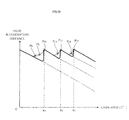
- FIG. 18 is a diagram showing the relationship between the lean angle of the motorcycle 10 and an illumination distance of the headlight illuminating the path of the motorcycle 10 according to the first embodiment of the present invention.
- the points P8 to P17 correspond to situations shown in FIGS. 8 to 17 , respectively.
- a path irradiation range (which means a distance on the path 80 from the motorcycle 10 to the most distal end of the illumination range) becomes shorter along with the increase in the lean angle.
- the sub headlight light source 13La is turned on so that the illumination range SH 1 of the sub headlight light source 13La is produced (P8). This extends the path irradiation range.
- the brightness of the sub headlight light source 13La increases to enlarge the illumination range SH 1 , thus extending the path irradiation range (P9 to P10).
- the cut-off line LL 1 of the sub headlight light source 13La approaches to the motorcycle 10 along with the increase in the lean angle.
- the brightness of the sub headlight light source 13La increases from the first brightness Q 1 to the second brightness Q 2 , to enlarge the illumination range SH 1 .
- the speed of movement of the cut-off line LL 1 to the motorcycle 10 drops, which suppresses a reduction in the path irradiation range along with the increase in the lean angle (P11).
- the sub headlight light source 13Lb When the lean angle further increases, the sub headlight light source 13Lb is turned on so that the illumination range SH 2 of the sub headlight light source 13Lb is produced. Then, along with the increase in the lean angle, the brightness of the sub headlight light source 13Lb increases to enlarge the illumination range SH 2 , thus extending the path irradiation range (P12).
- the cut-off line LL 2 of the sub headlight light source 13Lb approaches to the motorcycle 10 along with the increase in the lean angle.
- the brightness of the sub headlight light source 13Lb increases from the first brightness Q 1 to the second brightness Q 2 , to enlarge the illumination range SH 2 .
- the speed of movement of the cut-off line LL 2 to the motorcycle 10 drops, which suppresses a reduction in the path irradiation range along with the increase in the lean angle (P14).
- the sub headlight light source 13Lc When the lean angle further increases, the sub headlight light source 13Lc is turned on so that the illumination range SH 3 of the sub headlight light source 13Lc is produced. Then, along with the increase in the lean angle, the brightness of the sub headlight light source 13Lc increases to enlarge the illumination range SH 3 , thus extending the path irradiation range (P15).
- the cut-off line LL 3 of the sub headlight light source 13Lc approaches to the motorcycle 10 along with the increase in the lean angle.
- the brightness of the sub headlight light source 13Lc increases from the first brightness Q 1 to the second brightness Q 2 , to enlarge the illumination range SH 3 .
- the speed of movement of the cut-off line LL 3 to the motorcycle 10 drops, which suppresses a reduction in the path irradiation range along with the increase in the lean angle (P17).
- the present invention is not limited to this example.
- a second embodiment is adoptable.
- FIG. 19 is a chart showing the relationship between the lean angle of the motorcycle 10 and the brightnesses of the sub headlight light sources 13La to 13Lc according to the second embodiment of the present invention.
- the upper value U (U 1 to U 3 ) is not set.
- the sub headlight light source 13 (13La to 13Lc) starts to light up, and the brightness of the sub headlight light source 13 (13La to 13Lc) gradually increases in accordance with an increase in the lean angle.
- the lean angle of the motorcycle 10 takes the reference value K (K 1 to K 3 )
- the sub headlight light source 13 (13La to 13Lc) lights up with the second brightness Q 2 .
- the sub headlight light source 13 (13La to 13Lc) lights up in the same manner as in the first embodiment ( FIG. 4 ), except that, at a time point when the lean angle takes the reference value K, the sub headlight light source 13 (13La to 13Lc) lights up with the second brightness Q 2 . Therefore, a description of the manner will be omitted.
- FIG. 20 is a diagram showing the relationship between the lean angle of the motorcycle 10 and the illumination distance of the headlight illuminating the path of the motorcycle 10 according to the second embodiment of the present invention.
- the points P8, P9, P10, P12, P13, P15, and P16 correspond to situations shown in FIGS. 8 , 9 , 10 , 12 , 13 , 15 , and 16 , respectively.
- the path irradiation range becomes shorter along with the increase in the lean angle.
- the sub headlight light source 13La is turned on so that the illumination range SH 1 of the sub headlight light source 13La is produced (P8). This extends the path irradiation range.
- the brightness of the sub headlight light source 13La increases to enlarge the illumination range SH 1 , thus extending the path irradiation range (P9).
- the sub headlight light source 13La lights up with the second brightness Q 2 (P10).
- the cut-off line LL 1 of the sub headlight light source 13La approaches to the motorcycle 10 along with the increase in the lean angle.
- the sub headlight light source 13Lb is turned on so that the illumination range SH 2 of the sub headlight light source 13Lb is produced.
- the brightness of the sub headlight light source 13Lb increases to enlarge the illumination range SH 2 , thus extending the path irradiation range (P12).
- the sub headlight light source 13Lb lights up with the second brightness Q 2 (P13).
- the cut-off line LL 2 of the sub headlight light source 13Lb approaches to the motorcycle 10 along with the increase in the lean angle.
- the sub headlight light source 13Lc is turned on so that the illumination range SH 3 of the sub headlight light source 13Lc is produced.
- the brightness of the sub headlight light source 13Lc increases to enlarge the illumination range SH 3 , thus extending the path irradiation range (P 15).
- the sub headlight light source 13Lc lights up with the second brightness Q 2 (P16).
- the sub headlight light source 13La to 13Lc lights up with a brightness lower than the first brightness Q 1 (the second brightness Q 2 in the second embodiment), and when the lean angle reaches the reference value K, the sub headlight light source 13La to 13Lc lights up with the first brightness Q 1 (the second brightness Q 2 in the second embodiment). Accordingly, when the illumination range of the low beam light source 11L or the sub headlight light source 13La or 13Lb that has been already turned on is moving away from the position the rider desires to see, the illumination range of the sub headlight light source 13La to 13Lc that is subsequently turned on can spread over the position the rider desires to see.
- the cut-off line LL 1 to LL 3 of the sub headlight light source 13La to 13Lc that is subsequently turned on is likely to be conspicuous.
- the illumination range of the sub headlight light source 13La to 13Lc that is subsequently turned on is enlarged along with an increase in the brightness. Therefore, an effect of reducing the speed of approach of the cut-off line LL 1 to LL 3 to the motorcycle 10 is exerted. This enables suppression of an uncomfortable feeling, which may otherwise be given to the rider.
- the sub headlight light source 13La to 13Lc lights up with a brightness lower than the first brightness Q 1 (the second brightness Q 2 in the second embodiment), and when the lean angle subsequently reaches the reference value K (K 1 to K 3 ), the sub headlight light source 13La to 13Lc lights up with the first brightness Q 1 (the second brightness Q 2 in the second embodiment).
- This enables suppression of occurrence of a situation where the sub headlight light sources 13La to 13Lc suddenly lights up with a high brightness, which may make the rider feel uncomfortable.
- the sub headlight 13 is composed of the sub headlight units 13L and 13R, each of which is provided at each side with respect to the width direction of the vehicle.
- the present invention is not limited to this example.
- the sub headlight units 13L and 13R each provided at each side with respect to the width direction of the vehicle are formed integral with each other, as a single sub headlight unit.
- the single sub headlight unit has, at each side thereof with respect to the width direction of the vehicle, a plurality of headlight light sources that generate illumination ranges at one side with respect to the width direction of the vehicle.
- each of the sub headlight units 13L and 13R is a physically integrated unit.
- the present invention is not limited to this example. It may be possible that the sub headlight unit 13L is physically divided into the sub headlight light sources 13La to 13Lc. In this case, it may be possible that these sub headlight light sources 13La to 13Lc are assembled into a single sub headlight unit 13L which is then installed in the motorcycle 10 (vehicle). It may be also possible that each of the sub headlight light sources 13La to 13Lc is individually installed in the motorcycle 10. In this case, the sub headlight light sources 13La to 13Lc, in a state of being installed in the motorcycle 10, constitute a single sub headlight unit 13L.
- the sub headlight units 13L and 13R are members separate from the main headlight 11.
- the present invention is not limited to this example. It may be acceptable that a sub headlight unit is integrated with a main headlight.
- the lean angle sensor 22 and the vehicle speed sensor 23 correspond to a detection part for detecting variables available for obtaining the lean angle of the motorcycle 10.
- the detection part includes the lean angle sensor 22 and the vehicle speed sensor 23 in these embodiments, the present invention is not limited to this example.
- the detection part may include the lean angle sensor 22 while not including the vehicle speed sensor 23.
- the controller 20 corresponds to a control part of the present invention.
- a hardware configuration of the present invention is not limited to this example.
- the control part determines whether or not the lean angle of the motorcycle 10 has reached the reference value based on the variables detected by the detection part. At this time, it is not always necessary that the control part calculates the lean angle. No particular limitation is put on details of processing performed in the control part.
- a memory provided in the controller 20 serving as the control part stores, in the form of data, a table in which the angular velocity (roll rate) and the vehicle speed are associated with a result of whether or not the lean angle has reached a first reference value.
- the control part refers to the table based on the angular velocity and the vehicle speed, and thereby can determine whether or not the lean angle has reached the first reference value without calculating the lean angle.
- the lean angle is the angle of inclination of the vehicle body to the inner side of a curve relative to the upright state (vertical direction).
- the lean angle may be the angle of inclination of the vehicle body to the inner side of a curve relative to a direction perpendicular to a road surface.
- a method and a device for measuring the angle of inclination of the vehicle body to the inner side of a curve relative to the direction perpendicular to the road surface conventionally known ones are adoptable.
- the sub headlight unit 13L and 13R are members separate from the control part (controller 20) and the detection part (the lean angle sensor 22 and the vehicle speed sensor 23).
- the present invention is not limited to this example.
- the sub headlight unit may include at least one of the control part, the communication part, and the detection part.
- three sub headlight light sources are provided at each side of the vehicle with respect to the width direction of the vehicle.
- the number of light sources it is preferable that the number of sub headlight light sources that illuminate one side of the vehicle with respect to the width direction of the vehicle is at least three.
- each of the sub headlight light sources and the low beam light source is constituted of one light source, and one reference value is set for this one light source.
- the number of light sources that constitute one sub headlight light source or the low beam light source is not particularly limited.
- one sub headlight light source or the low beam light source is constituted of a plurality of light sources and one reference value is set for the plurality of light sources.
- the sub headlight light source may be configured such that a turn-on function in accordance with the lean angle is manually activated or deactivated.
- the function is manually put into a standby state and, in the standby state, the sub headlight light source is turned on in accordance with the lean angle.
- the sub headlight light source is turned on not manually but in accordance with the lean angle.
- flashing/turn-off is manually switched.
- the main headlight the illuminating direction is manually switched.
- the sub headlight light source is different from the flasher and the main headlight.
- the sub headlight light source may be also configured such that an instruction for turn-on or turn-off is manually inputted.
- the instruction for turn-on or turn-off is manually inputted.
- the sub headlight light source is turned on irrespective of the lean angle.
- the instruction for turn-off is inputted, the sub headlight light source is turned off irrespective of the lean angle.
- the sub headlight system includes an input part (for example, a switch) to which the instruction for turning on or off the sub headlight light source is manually inputted.
- the control part turns on or off the sub headlight light source in accordance with the instruction.
- the control part changes the brightness of the sub headlight light source in accordance with the lean angle.
- the sub headlight light source is different from the flasher and the main headlight, in that a function of turning on the sub headlight light source in accordance with the lean angle is provided.
- the sub headlight light source may be configured such that, when the lean angle is equal to or larger than a minimum reference value, the brightness is changed in accordance with the lean angle, while when the lean angle is less than the minimum reference value (for example, at a time of running straight ahead), the brightness is manually changed.
- the sub headlight light source is different from the flasher and the main headlight, in that a function of turning on the sub headlight light source in accordance with the lean angle is provided.
- the sub headlight light source is turned on in accordance with the lean angle.
- the sub headlight light source is turned on in accordance with the lean angle because the sub headlight light source functions mainly as a light for ensuring the field of view of the rider of the vehicle. Therefore, in a well-lit situation, for example, in daytime, the sub headlight light source may not necessarily be turned on in accordance with the lean angle.
- the present invention is not limited to this example.
- a temperature detector for detecting the temperature of the sub headlight light source or the vicinity thereof may be provided.
- the control part performs such a control that the brightness of the sub headlight light source increases as the temperature detected by the temperature detector is higher.
- the control part may perform such a control that the brightness of the sub headlight light source increases in a case where the temperature detected by the temperature detector is equal to or higher than a predetermined temperature. This can correct a reduction in the brightness of the sub headlight light source caused by a temperature rise.
- the control part performs a distance information acquisition process and an adjustment process.
- distance information acquisition process distance information indicating a distance the vehicle has traveled is acquired from a tripmeter or the like.
- adjustment process the brightness of the sub headlight light source, which changes in accordance with the lean angle of the vehicle, is adjusted based on the distance information.
- the control part controls such a control that the brightness of the sub headlight light source increases as the distance the vehicle has traveled is longer. This can correct a reduction in the brightness of the sub headlight light source caused by a long-term use.
- the control part performs a time information acquisition process and an adjustment process.
- time information acquisition process time information indicating a period of use of the vehicle or the sub headlight light source is acquired.
- adjustment process the brightness of the sub headlight light source, which changes in accordance with the lean angle of the vehicle, is adjusted based on the time information acquired as a result of the time information acquisition process.
- the control part can acquire the time information based on information of the current time, which is obtained by a clock or the like, and information indicating the time and date when the use of the vehicle or the sub headlight light source was started, which is stored in the memory.
- the vehicle is configured to acquire, through wireless communication, the time information indicating the period of use of the vehicle or the sub headlight light source from an external storage device (for example, a server) remote from the vehicle.
- the control part performs such a control that the brightness of the sub headlight light source increases as the period of use indicated by the time information is longer. This can correct a reduction in the brightness of the sub headlight light source caused by a long-term use.
- the brightness of the sub headlight light source which changes in accordance with the lean angle, is corrected based on the temperature, the travel distance, and the period of use.
- a correction adjustment process
- the lean angle of the vehicle is in a range of at least the lower limit value and less than the reference value
- such a correction adjustment process
- an output of the sub headlight light source can be made without limitation, to make it possible to ensure a wide illumination range.
- the present invention is not limited to this example.
- the above-described brightness control may be performed irrespective of the lean angle of the vehicle.
Landscapes
- Engineering & Computer Science (AREA)
- Mechanical Engineering (AREA)
- Lighting Device Outwards From Vehicle And Optical Signal (AREA)
Applications Claiming Priority (1)
| Application Number | Priority Date | Filing Date | Title |
|---|---|---|---|
| JP2012104063A JP2013230773A (ja) | 2012-04-27 | 2012-04-27 | リーン姿勢で旋回する車両用のサブヘッドライトユニット及びサブヘッドライトシステム、並びにリーン姿勢で旋回する車両 |
Publications (3)
| Publication Number | Publication Date |
|---|---|
| EP2657080A2 true EP2657080A2 (de) | 2013-10-30 |
| EP2657080A3 EP2657080A3 (de) | 2013-12-25 |
| EP2657080B1 EP2657080B1 (de) | 2017-04-05 |
Family
ID=48143487
Family Applications (1)
| Application Number | Title | Priority Date | Filing Date |
|---|---|---|---|
| EP13164320.7A Active EP2657080B1 (de) | 2012-04-27 | 2013-04-18 | Unterscheinwerfereinheit und Unterscheinwerfersystem zur Verwendung in einem Fahrzeug, das sich in Kurven lehnt, sowie Fahrzeug, das sich in Kurven lehnt |
Country Status (6)
| Country | Link |
|---|---|
| EP (1) | EP2657080B1 (de) |
| JP (1) | JP2013230773A (de) |
| CN (1) | CN103373416B (de) |
| AP (1) | AP3877A (de) |
| BR (1) | BR102013007924B1 (de) |
| ES (1) | ES2622903T3 (de) |
Cited By (7)
| Publication number | Priority date | Publication date | Assignee | Title |
|---|---|---|---|---|
| EP2792584A1 (de) * | 2013-04-17 | 2014-10-22 | Yamaha Hatsudoki Kabushiki Kaisha | Scheinwerfereinheit zur Verwendung in einem Fahrzeug, das sich in Kurven lehnt, und Verfahren zur Steuerung eines Scheinwerfersystems |
| DE102016107233A1 (de) | 2015-04-24 | 2016-10-27 | Zkw Group Gmbh | Scheinwerfer für Fahrzeuge, insbesondere für einspurige Fahrzeuge |
| AT517408A1 (de) * | 2015-06-30 | 2017-01-15 | Zkw Group Gmbh | Scheinwerfer für Fahrzeuge, insbesondere für einspurige Kraftfahrzeuge |
| EP3150434A1 (de) * | 2012-05-31 | 2017-04-05 | Yamaha Hatsudoki Kabushiki Kaisha | Unterscheinwerfereinheit und unterscheinwerfersystem zur verwendung in einem fahrzeug, das sich in kurven neigt, und fahrzeug, das sich in kurven neigt, und verfahren zur steuerung einer unterscheinwerfereinheit zur verwendung in einem fahrzeug, das sich in kurven neigt |
| US10023103B2 (en) | 2013-09-13 | 2018-07-17 | J.W. Speaker, Corporation | Systems and methods for illumination control and distribution during a vehicle bank |
| EP3802298B1 (de) * | 2018-06-05 | 2022-12-21 | Indian Motorcycle International, LLC | Adaptives beleuchtungssystem für zweirädrige fahrzeuge |
| WO2025256692A1 (de) * | 2024-06-11 | 2025-12-18 | Bayerische Motoren Werke Aktiengesellschaft | Kraftfahrzeug |
Families Citing this family (2)
| Publication number | Priority date | Publication date | Assignee | Title |
|---|---|---|---|---|
| US9324195B2 (en) | 2013-02-26 | 2016-04-26 | Polaris Industries Inc. | Recreational vehicle interactive, telemetry, mapping, and trip planning system |
| CN108604320B (zh) * | 2016-02-10 | 2022-09-23 | 北极星工业有限公司 | 休闲车辆组管理系统 |
Citations (1)
| Publication number | Priority date | Publication date | Assignee | Title |
|---|---|---|---|---|
| WO2010061651A1 (ja) | 2008-11-25 | 2010-06-03 | ヤマハ発動機株式会社 | 前照灯ユニット及び自動二輪車 |
Family Cites Families (7)
| Publication number | Priority date | Publication date | Assignee | Title |
|---|---|---|---|---|
| DE10102292C1 (de) * | 2001-01-19 | 2002-09-05 | Stephan Gropp | Scheinwerfereinheit für einspurige Zweiradfahrzeuge |
| US7445364B2 (en) * | 2001-01-19 | 2008-11-04 | Stephan Gropp | Headlight unit for single-track two-wheeled vehicles |
| JP4170928B2 (ja) * | 2004-02-18 | 2008-10-22 | 株式会社小糸製作所 | 車両用灯具 |
| CN100404357C (zh) * | 2004-10-07 | 2008-07-23 | 雅马哈发动机株式会社 | 二轮摩托车的照明灯的照射区域控制方法和该照明灯 |
| DE102004055883A1 (de) * | 2004-11-19 | 2006-06-01 | Audi Ag | Kraftfahrzeug mit einer Beleuchtungseinrichtung umfassend ein Steuergerät und ein über das Steuergerät zum Ausleuchten einer Kurve in Abhängigkeit des über einen Lenkwinkelsensor erfassten Lenkwinkels ansteuerbares Leuchtmittel |
| JP4864562B2 (ja) * | 2006-06-26 | 2012-02-01 | 株式会社小糸製作所 | 二輪車用灯具システム |
| US8080942B2 (en) * | 2009-02-24 | 2011-12-20 | Volkswagen Ag | System and method for electronic adaptive front-lighting |
-
2012
- 2012-04-27 JP JP2012104063A patent/JP2013230773A/ja active Pending
-
2013
- 2013-04-02 BR BR102013007924-3A patent/BR102013007924B1/pt active IP Right Grant
- 2013-04-18 ES ES13164320.7T patent/ES2622903T3/es active Active
- 2013-04-18 EP EP13164320.7A patent/EP2657080B1/de active Active
- 2013-04-23 AP AP2013006828A patent/AP3877A/en active
- 2013-04-27 CN CN201310153020.8A patent/CN103373416B/zh active Active
Patent Citations (1)
| Publication number | Priority date | Publication date | Assignee | Title |
|---|---|---|---|---|
| WO2010061651A1 (ja) | 2008-11-25 | 2010-06-03 | ヤマハ発動機株式会社 | 前照灯ユニット及び自動二輪車 |
Cited By (15)
| Publication number | Priority date | Publication date | Assignee | Title |
|---|---|---|---|---|
| EP3150433A1 (de) * | 2012-05-31 | 2017-04-05 | Yamaha Hatsudoki Kabushiki Kaisha | Unterscheinwerfereinheit und unterscheinwerfersystem zur verwendung in einem fahrzeug, das sich in kurven neigt, und fahrzeug, das sich in kurven neigt, und verfahren zur steuerung einer unterscheinwerfereinheit zur verwendung in einem fahrzeug, das sich in kurven neigt |
| EP2669116B1 (de) * | 2012-05-31 | 2018-06-20 | Yamaha Hatsudoki Kabushiki Kaisha | Unterscheinwerfereinheit und Unterscheinwerfersystem zur Verwendung in einem Fahrzeug, das sich in Kurven lehnt, und Fahrzeug, das sich in Kurven lehnt, und Verfahren zur Steuerung einer Unterscheinwerfereinheit zur Verwendung in einem Fahrzeug, das sich in Kurven lehnt |
| EP3150434A1 (de) * | 2012-05-31 | 2017-04-05 | Yamaha Hatsudoki Kabushiki Kaisha | Unterscheinwerfereinheit und unterscheinwerfersystem zur verwendung in einem fahrzeug, das sich in kurven neigt, und fahrzeug, das sich in kurven neigt, und verfahren zur steuerung einer unterscheinwerfereinheit zur verwendung in einem fahrzeug, das sich in kurven neigt |
| EP2792584A1 (de) * | 2013-04-17 | 2014-10-22 | Yamaha Hatsudoki Kabushiki Kaisha | Scheinwerfereinheit zur Verwendung in einem Fahrzeug, das sich in Kurven lehnt, und Verfahren zur Steuerung eines Scheinwerfersystems |
| US10676018B2 (en) | 2013-09-13 | 2020-06-09 | J.W. Speaker, Corporation | Systems and methods for illumination control and distribution during a vehicle bank |
| US10023103B2 (en) | 2013-09-13 | 2018-07-17 | J.W. Speaker, Corporation | Systems and methods for illumination control and distribution during a vehicle bank |
| US11447062B2 (en) | 2013-09-13 | 2022-09-20 | J.W. Speaker Corporation | Systems and methods for illumination control and distribution during a vehicle bank |
| US11987168B2 (en) | 2013-09-13 | 2024-05-21 | J.W. Speaker Corporation | Systems and methods for illumination control and distribution during a vehicle bank |
| AT517135B1 (de) * | 2015-04-24 | 2017-04-15 | Zkw Group Gmbh | Scheinwerfer für Fahrzeuge, insbesondere für einspurige Fahrzeuge |
| DE102016107233A1 (de) | 2015-04-24 | 2016-10-27 | Zkw Group Gmbh | Scheinwerfer für Fahrzeuge, insbesondere für einspurige Fahrzeuge |
| DE102016107233B4 (de) * | 2015-04-24 | 2024-08-01 | Zkw Group Gmbh | Scheinwerfer für Fahrzeuge, insbesondere für einspurige Fahrzeuge |
| AT517408B1 (de) * | 2015-06-30 | 2017-09-15 | Zkw Group Gmbh | Scheinwerfer für Fahrzeuge, insbesondere für einspurige Kraftfahrzeuge |
| AT517408A1 (de) * | 2015-06-30 | 2017-01-15 | Zkw Group Gmbh | Scheinwerfer für Fahrzeuge, insbesondere für einspurige Kraftfahrzeuge |
| EP3802298B1 (de) * | 2018-06-05 | 2022-12-21 | Indian Motorcycle International, LLC | Adaptives beleuchtungssystem für zweirädrige fahrzeuge |
| WO2025256692A1 (de) * | 2024-06-11 | 2025-12-18 | Bayerische Motoren Werke Aktiengesellschaft | Kraftfahrzeug |
Also Published As
| Publication number | Publication date |
|---|---|
| JP2013230773A (ja) | 2013-11-14 |
| EP2657080A3 (de) | 2013-12-25 |
| AP2013006828A0 (en) | 2013-04-30 |
| EP2657080B1 (de) | 2017-04-05 |
| AP3877A (en) | 2016-10-31 |
| BR102013007924B1 (pt) | 2021-03-02 |
| ES2622903T3 (es) | 2017-07-07 |
| CN103373416B (zh) | 2017-04-26 |
| BR102013007924A2 (pt) | 2015-06-16 |
| CN103373416A (zh) | 2013-10-30 |
Similar Documents
| Publication | Publication Date | Title |
|---|---|---|
| EP2657080B1 (de) | Unterscheinwerfereinheit und Unterscheinwerfersystem zur Verwendung in einem Fahrzeug, das sich in Kurven lehnt, sowie Fahrzeug, das sich in Kurven lehnt | |
| EP2657078B1 (de) | Scheinwerfereinheit und Scheinwerfersystem zur Verwendung in einem Fahrzeug, das sich in Kurven lehnt, und Fahrzeug, das sich in Kurven lehnt, und Verfahren zur Steuerung einer Scheinwerfereinheit | |
| US8987991B2 (en) | Sub headlight unit and sub headlight system for use in vehicle that leans into turns, and vehicle that leans into turns | |
| EP2641778B1 (de) | Unterscheinwerfereinheit, Verfahren zur Steuerung einer Unterscheinwerfereinheit und Unterscheinwerfersystem zur Verwendung in einem Fahrzeug, das sich in Kurven legt, und Fahrzeug, das sich in Kurven legt | |
| EP2669116B1 (de) | Unterscheinwerfereinheit und Unterscheinwerfersystem zur Verwendung in einem Fahrzeug, das sich in Kurven lehnt, und Fahrzeug, das sich in Kurven lehnt, und Verfahren zur Steuerung einer Unterscheinwerfereinheit zur Verwendung in einem Fahrzeug, das sich in Kurven lehnt | |
| US8912722B2 (en) | Sub headlight unit and sub headlight system for use in vehicle that leans into turns, and vehicle that leans into turns | |
| EP2669161B1 (de) | Sich in Kurven lehnendes Fahrzeug mit Unterscheinwerfereinheit | |
| EP2676872B1 (de) | Unterscheinwerfereinheit, Scheinwerfereinheit, Scheinwerfersystem für Fahrzeuge, das sich in Kurven legt, Fahrzeug, das sich in Kurven legt und Verfahren zum Steuern einer Unterscheinwerfereinheit für Fahrzeuge, die sich in Kurven legen | |
| EP2657076B1 (de) | Scheinwerfereinheit für Fahrzeuge, die sich in Kurven legen, und deren Verfahren | |
| EP2669114B1 (de) | Fahrzeug, das sich in Kurven lehnt, mit Unterscheinwerfereinheit oder Unterscheinwerfersystem, und Verfahren zum Steuern vom Unterscheinwerfereinheit oder Unterscheinwerfersystem zur Verwendung in einem Fahrzeug, das sich in Kurven lehnt | |
| EP2669163B1 (de) | Unterscheinwerfereinheit und Unterscheinwerfersystem zur Verwendung in einem Fahrzeug, das sich in Kurven lehnt, und Verfahren zur Steuerung einer Unterscheinwerfereinheit | |
| EP2669162B1 (de) | Unterscheinwerfereinheit zur Verwendung in einem sich in Kurven neigenden Fahrzeug | |
| OA18846A (en) | Sub headlight unit and sub headlight system for use in vehicle that leans into turns, and vehicle that leans into turns. | |
| OA18077A (en) | Headlight unit and headlight system for use in vehicle that leans into turns, vehicle that leans into turns, and method for controlling a headlight unit. | |
| OA16382A (en) | Sub headlight unit and sub headlight system for use in vehicle that leans into turns, and vehicle that leans into turns. | |
| OA16383A (en) | Headlight unit and headlight system for use in vehicle that leans into turns, vehicle that leans into turns, and method for controlling a headlight unit. | |
| OA18076A (en) | Sub headlight unit and sub headlight system for use in vehicle that leans into turns, and vehicle that leans into turns, and method for controlling light emission of a sub headlight unit. |
Legal Events
| Date | Code | Title | Description |
|---|---|---|---|
| PUAI | Public reference made under article 153(3) epc to a published international application that has entered the european phase |
Free format text: ORIGINAL CODE: 0009012 |
|
| AK | Designated contracting states |
Kind code of ref document: A2 Designated state(s): AL AT BE BG CH CY CZ DE DK EE ES FI FR GB GR HR HU IE IS IT LI LT LU LV MC MK MT NL NO PL PT RO RS SE SI SK SM TR |
|
| AX | Request for extension of the european patent |
Extension state: BA ME |
|
| PUAL | Search report despatched |
Free format text: ORIGINAL CODE: 0009013 |
|
| AK | Designated contracting states |
Kind code of ref document: A3 Designated state(s): AL AT BE BG CH CY CZ DE DK EE ES FI FR GB GR HR HU IE IS IT LI LT LU LV MC MK MT NL NO PL PT RO RS SE SI SK SM TR |
|
| AX | Request for extension of the european patent |
Extension state: BA ME |
|
| RIC1 | Information provided on ipc code assigned before grant |
Ipc: B60Q 1/12 20060101ALI20131120BHEP Ipc: B60Q 1/18 20060101AFI20131120BHEP Ipc: B62J 6/02 20060101ALI20131120BHEP |
|
| 17P | Request for examination filed |
Effective date: 20140430 |
|
| RBV | Designated contracting states (corrected) |
Designated state(s): AL AT BE BG CH CY CZ DE DK EE ES FI FR GB GR HR HU IE IS IT LI LT LU LV MC MK MT NL NO PL PT RO RS SE SI SK SM TR |
|
| 17Q | First examination report despatched |
Effective date: 20140611 |
|
| GRAP | Despatch of communication of intention to grant a patent |
Free format text: ORIGINAL CODE: EPIDOSNIGR1 |
|
| INTG | Intention to grant announced |
Effective date: 20160225 |
|
| INTC | Intention to grant announced (deleted) | ||
| GRAP | Despatch of communication of intention to grant a patent |
Free format text: ORIGINAL CODE: EPIDOSNIGR1 |
|
| GRAJ | Information related to disapproval of communication of intention to grant by the applicant or resumption of examination proceedings by the epo deleted |
Free format text: ORIGINAL CODE: EPIDOSDIGR1 |
|
| GRAP | Despatch of communication of intention to grant a patent |
Free format text: ORIGINAL CODE: EPIDOSNIGR1 |
|
| INTG | Intention to grant announced |
Effective date: 20161116 |
|
| INTG | Intention to grant announced |
Effective date: 20161125 |
|
| GRAS | Grant fee paid |
Free format text: ORIGINAL CODE: EPIDOSNIGR3 |
|
| GRAA | (expected) grant |
Free format text: ORIGINAL CODE: 0009210 |
|
| AK | Designated contracting states |
Kind code of ref document: B1 Designated state(s): AL AT BE BG CH CY CZ DE DK EE ES FI FR GB GR HR HU IE IS IT LI LT LU LV MC MK MT NL NO PL PT RO RS SE SI SK SM TR |
|
| REG | Reference to a national code |
Ref country code: GB Ref legal event code: FG4D |
|
| REG | Reference to a national code |
Ref country code: CH Ref legal event code: EP |
|
| REG | Reference to a national code |
Ref country code: AT Ref legal event code: REF Ref document number: 881485 Country of ref document: AT Kind code of ref document: T Effective date: 20170415 |
|
| REG | Reference to a national code |
Ref country code: FR Ref legal event code: PLFP Year of fee payment: 5 |
|
| REG | Reference to a national code |
Ref country code: IE Ref legal event code: FG4D |
|
| REG | Reference to a national code |
Ref country code: DE Ref legal event code: R096 Ref document number: 602013019339 Country of ref document: DE |
|
| REG | Reference to a national code |
Ref country code: ES Ref legal event code: FG2A Ref document number: 2622903 Country of ref document: ES Kind code of ref document: T3 Effective date: 20170707 |
|
| REG | Reference to a national code |
Ref country code: NL Ref legal event code: MP Effective date: 20170405 |
|
| REG | Reference to a national code |
Ref country code: LT Ref legal event code: MG4D |
|
| REG | Reference to a national code |
Ref country code: AT Ref legal event code: MK05 Ref document number: 881485 Country of ref document: AT Kind code of ref document: T Effective date: 20170405 |
|
| PG25 | Lapsed in a contracting state [announced via postgrant information from national office to epo] |
Ref country code: NL Free format text: LAPSE BECAUSE OF FAILURE TO SUBMIT A TRANSLATION OF THE DESCRIPTION OR TO PAY THE FEE WITHIN THE PRESCRIBED TIME-LIMIT Effective date: 20170405 |
|
| PG25 | Lapsed in a contracting state [announced via postgrant information from national office to epo] |
Ref country code: GR Free format text: LAPSE BECAUSE OF FAILURE TO SUBMIT A TRANSLATION OF THE DESCRIPTION OR TO PAY THE FEE WITHIN THE PRESCRIBED TIME-LIMIT Effective date: 20170706 Ref country code: LT Free format text: LAPSE BECAUSE OF FAILURE TO SUBMIT A TRANSLATION OF THE DESCRIPTION OR TO PAY THE FEE WITHIN THE PRESCRIBED TIME-LIMIT Effective date: 20170405 Ref country code: HR Free format text: LAPSE BECAUSE OF FAILURE TO SUBMIT A TRANSLATION OF THE DESCRIPTION OR TO PAY THE FEE WITHIN THE PRESCRIBED TIME-LIMIT Effective date: 20170405 Ref country code: AT Free format text: LAPSE BECAUSE OF FAILURE TO SUBMIT A TRANSLATION OF THE DESCRIPTION OR TO PAY THE FEE WITHIN THE PRESCRIBED TIME-LIMIT Effective date: 20170405 Ref country code: NO Free format text: LAPSE BECAUSE OF FAILURE TO SUBMIT A TRANSLATION OF THE DESCRIPTION OR TO PAY THE FEE WITHIN THE PRESCRIBED TIME-LIMIT Effective date: 20170705 Ref country code: FI Free format text: LAPSE BECAUSE OF FAILURE TO SUBMIT A TRANSLATION OF THE DESCRIPTION OR TO PAY THE FEE WITHIN THE PRESCRIBED TIME-LIMIT Effective date: 20170405 |
|
| PG25 | Lapsed in a contracting state [announced via postgrant information from national office to epo] |
Ref country code: BG Free format text: LAPSE BECAUSE OF FAILURE TO SUBMIT A TRANSLATION OF THE DESCRIPTION OR TO PAY THE FEE WITHIN THE PRESCRIBED TIME-LIMIT Effective date: 20170705 Ref country code: LV Free format text: LAPSE BECAUSE OF FAILURE TO SUBMIT A TRANSLATION OF THE DESCRIPTION OR TO PAY THE FEE WITHIN THE PRESCRIBED TIME-LIMIT Effective date: 20170405 Ref country code: IS Free format text: LAPSE BECAUSE OF FAILURE TO SUBMIT A TRANSLATION OF THE DESCRIPTION OR TO PAY THE FEE WITHIN THE PRESCRIBED TIME-LIMIT Effective date: 20170805 Ref country code: PL Free format text: LAPSE BECAUSE OF FAILURE TO SUBMIT A TRANSLATION OF THE DESCRIPTION OR TO PAY THE FEE WITHIN THE PRESCRIBED TIME-LIMIT Effective date: 20170405 Ref country code: RS Free format text: LAPSE BECAUSE OF FAILURE TO SUBMIT A TRANSLATION OF THE DESCRIPTION OR TO PAY THE FEE WITHIN THE PRESCRIBED TIME-LIMIT Effective date: 20170405 Ref country code: SE Free format text: LAPSE BECAUSE OF FAILURE TO SUBMIT A TRANSLATION OF THE DESCRIPTION OR TO PAY THE FEE WITHIN THE PRESCRIBED TIME-LIMIT Effective date: 20170405 |
|
| REG | Reference to a national code |
Ref country code: CH Ref legal event code: PL |
|
| REG | Reference to a national code |
Ref country code: DE Ref legal event code: R097 Ref document number: 602013019339 Country of ref document: DE |
|
| REG | Reference to a national code |
Ref country code: IE Ref legal event code: MM4A |
|
| PG25 | Lapsed in a contracting state [announced via postgrant information from national office to epo] |
Ref country code: SK Free format text: LAPSE BECAUSE OF FAILURE TO SUBMIT A TRANSLATION OF THE DESCRIPTION OR TO PAY THE FEE WITHIN THE PRESCRIBED TIME-LIMIT Effective date: 20170405 Ref country code: MC Free format text: LAPSE BECAUSE OF FAILURE TO SUBMIT A TRANSLATION OF THE DESCRIPTION OR TO PAY THE FEE WITHIN THE PRESCRIBED TIME-LIMIT Effective date: 20170405 Ref country code: EE Free format text: LAPSE BECAUSE OF FAILURE TO SUBMIT A TRANSLATION OF THE DESCRIPTION OR TO PAY THE FEE WITHIN THE PRESCRIBED TIME-LIMIT Effective date: 20170405 Ref country code: RO Free format text: LAPSE BECAUSE OF FAILURE TO SUBMIT A TRANSLATION OF THE DESCRIPTION OR TO PAY THE FEE WITHIN THE PRESCRIBED TIME-LIMIT Effective date: 20170405 Ref country code: CZ Free format text: LAPSE BECAUSE OF FAILURE TO SUBMIT A TRANSLATION OF THE DESCRIPTION OR TO PAY THE FEE WITHIN THE PRESCRIBED TIME-LIMIT Effective date: 20170405 Ref country code: DK Free format text: LAPSE BECAUSE OF FAILURE TO SUBMIT A TRANSLATION OF THE DESCRIPTION OR TO PAY THE FEE WITHIN THE PRESCRIBED TIME-LIMIT Effective date: 20170405 |
|
| PLBE | No opposition filed within time limit |
Free format text: ORIGINAL CODE: 0009261 |
|
| STAA | Information on the status of an ep patent application or granted ep patent |
Free format text: STATUS: NO OPPOSITION FILED WITHIN TIME LIMIT |
|
| PG25 | Lapsed in a contracting state [announced via postgrant information from national office to epo] |
Ref country code: CH Free format text: LAPSE BECAUSE OF NON-PAYMENT OF DUE FEES Effective date: 20170430 Ref country code: LI Free format text: LAPSE BECAUSE OF NON-PAYMENT OF DUE FEES Effective date: 20170430 Ref country code: LU Free format text: LAPSE BECAUSE OF NON-PAYMENT OF DUE FEES Effective date: 20170418 Ref country code: SM Free format text: LAPSE BECAUSE OF FAILURE TO SUBMIT A TRANSLATION OF THE DESCRIPTION OR TO PAY THE FEE WITHIN THE PRESCRIBED TIME-LIMIT Effective date: 20170405 |
|
| 26N | No opposition filed |
Effective date: 20180108 |
|
| REG | Reference to a national code |
Ref country code: BE Ref legal event code: MM Effective date: 20170430 |
|
| REG | Reference to a national code |
Ref country code: FR Ref legal event code: PLFP Year of fee payment: 6 |
|
| PG25 | Lapsed in a contracting state [announced via postgrant information from national office to epo] |
Ref country code: IE Free format text: LAPSE BECAUSE OF NON-PAYMENT OF DUE FEES Effective date: 20170418 |
|
| PG25 | Lapsed in a contracting state [announced via postgrant information from national office to epo] |
Ref country code: SI Free format text: LAPSE BECAUSE OF FAILURE TO SUBMIT A TRANSLATION OF THE DESCRIPTION OR TO PAY THE FEE WITHIN THE PRESCRIBED TIME-LIMIT Effective date: 20170405 Ref country code: BE Free format text: LAPSE BECAUSE OF NON-PAYMENT OF DUE FEES Effective date: 20170430 |
|
| PG25 | Lapsed in a contracting state [announced via postgrant information from national office to epo] |
Ref country code: MT Free format text: LAPSE BECAUSE OF NON-PAYMENT OF DUE FEES Effective date: 20170418 |
|
| PG25 | Lapsed in a contracting state [announced via postgrant information from national office to epo] |
Ref country code: HU Free format text: LAPSE BECAUSE OF FAILURE TO SUBMIT A TRANSLATION OF THE DESCRIPTION OR TO PAY THE FEE WITHIN THE PRESCRIBED TIME-LIMIT; INVALID AB INITIO Effective date: 20130418 |
|
| PG25 | Lapsed in a contracting state [announced via postgrant information from national office to epo] |
Ref country code: CY Free format text: LAPSE BECAUSE OF NON-PAYMENT OF DUE FEES Effective date: 20170405 |
|
| PG25 | Lapsed in a contracting state [announced via postgrant information from national office to epo] |
Ref country code: MK Free format text: LAPSE BECAUSE OF FAILURE TO SUBMIT A TRANSLATION OF THE DESCRIPTION OR TO PAY THE FEE WITHIN THE PRESCRIBED TIME-LIMIT Effective date: 20170405 |
|
| PG25 | Lapsed in a contracting state [announced via postgrant information from national office to epo] |
Ref country code: TR Free format text: LAPSE BECAUSE OF FAILURE TO SUBMIT A TRANSLATION OF THE DESCRIPTION OR TO PAY THE FEE WITHIN THE PRESCRIBED TIME-LIMIT Effective date: 20170405 |
|
| PG25 | Lapsed in a contracting state [announced via postgrant information from national office to epo] |
Ref country code: PT Free format text: LAPSE BECAUSE OF FAILURE TO SUBMIT A TRANSLATION OF THE DESCRIPTION OR TO PAY THE FEE WITHIN THE PRESCRIBED TIME-LIMIT Effective date: 20170405 |
|
| PG25 | Lapsed in a contracting state [announced via postgrant information from national office to epo] |
Ref country code: AL Free format text: LAPSE BECAUSE OF FAILURE TO SUBMIT A TRANSLATION OF THE DESCRIPTION OR TO PAY THE FEE WITHIN THE PRESCRIBED TIME-LIMIT Effective date: 20170405 |
|
| P01 | Opt-out of the competence of the unified patent court (upc) registered |
Effective date: 20230527 |
|
| PGFP | Annual fee paid to national office [announced via postgrant information from national office to epo] |
Ref country code: DE Payment date: 20250422 Year of fee payment: 13 |
|
| PGFP | Annual fee paid to national office [announced via postgrant information from national office to epo] |
Ref country code: ES Payment date: 20250529 Year of fee payment: 13 |
|
| PGFP | Annual fee paid to national office [announced via postgrant information from national office to epo] |
Ref country code: IT Payment date: 20250424 Year of fee payment: 13 |
|
| PGFP | Annual fee paid to national office [announced via postgrant information from national office to epo] |
Ref country code: FR Payment date: 20250425 Year of fee payment: 13 |
|
| PGFP | Annual fee paid to national office [announced via postgrant information from national office to epo] |
Ref country code: GB Payment date: 20260306 Year of fee payment: 14 |