EP2657164B1 - Dispositif d'alimentation papier - Google Patents
Dispositif d'alimentation papier Download PDFInfo
- Publication number
- EP2657164B1 EP2657164B1 EP11873155.3A EP11873155A EP2657164B1 EP 2657164 B1 EP2657164 B1 EP 2657164B1 EP 11873155 A EP11873155 A EP 11873155A EP 2657164 B1 EP2657164 B1 EP 2657164B1
- Authority
- EP
- European Patent Office
- Prior art keywords
- support frame
- sheet
- detector
- guide rail
- housing
- Prior art date
- Legal status (The legal status is an assumption and is not a legal conclusion. Google has not performed a legal analysis and makes no representation as to the accuracy of the status listed.)
- Active
Links
Images



Classifications
-
- B—PERFORMING OPERATIONS; TRANSPORTING
- B65—CONVEYING; PACKING; STORING; HANDLING THIN OR FILAMENTARY MATERIAL
- B65H—HANDLING THIN OR FILAMENTARY MATERIAL, e.g. SHEETS, WEBS, CABLES
- B65H7/00—Controlling article feeding, separating, pile-advancing, or associated apparatus, to take account of incorrect feeding, absence of articles, or presence of faulty articles
- B65H7/20—Controlling associated apparatus
-
- B—PERFORMING OPERATIONS; TRANSPORTING
- B65—CONVEYING; PACKING; STORING; HANDLING THIN OR FILAMENTARY MATERIAL
- B65H—HANDLING THIN OR FILAMENTARY MATERIAL, e.g. SHEETS, WEBS, CABLES
- B65H5/00—Feeding articles separated from piles; Feeding articles to machines
- B65H5/06—Feeding articles separated from piles; Feeding articles to machines by rollers or balls, e.g. between rollers
- B65H5/062—Feeding articles separated from piles; Feeding articles to machines by rollers or balls, e.g. between rollers between rollers or balls
-
- B—PERFORMING OPERATIONS; TRANSPORTING
- B65—CONVEYING; PACKING; STORING; HANDLING THIN OR FILAMENTARY MATERIAL
- B65H—HANDLING THIN OR FILAMENTARY MATERIAL, e.g. SHEETS, WEBS, CABLES
- B65H7/00—Controlling article feeding, separating, pile-advancing, or associated apparatus, to take account of incorrect feeding, absence of articles, or presence of faulty articles
- B65H7/02—Controlling article feeding, separating, pile-advancing, or associated apparatus, to take account of incorrect feeding, absence of articles, or presence of faulty articles by feelers or detectors
- B65H7/06—Controlling article feeding, separating, pile-advancing, or associated apparatus, to take account of incorrect feeding, absence of articles, or presence of faulty articles by feelers or detectors responsive to presence of faulty articles or incorrect separation or feed
-
- B—PERFORMING OPERATIONS; TRANSPORTING
- B65—CONVEYING; PACKING; STORING; HANDLING THIN OR FILAMENTARY MATERIAL
- B65H—HANDLING THIN OR FILAMENTARY MATERIAL, e.g. SHEETS, WEBS, CABLES
- B65H7/00—Controlling article feeding, separating, pile-advancing, or associated apparatus, to take account of incorrect feeding, absence of articles, or presence of faulty articles
- B65H7/02—Controlling article feeding, separating, pile-advancing, or associated apparatus, to take account of incorrect feeding, absence of articles, or presence of faulty articles by feelers or detectors
- B65H7/14—Controlling article feeding, separating, pile-advancing, or associated apparatus, to take account of incorrect feeding, absence of articles, or presence of faulty articles by feelers or detectors by photoelectric feelers or detectors
-
- B—PERFORMING OPERATIONS; TRANSPORTING
- B65—CONVEYING; PACKING; STORING; HANDLING THIN OR FILAMENTARY MATERIAL
- B65H—HANDLING THIN OR FILAMENTARY MATERIAL, e.g. SHEETS, WEBS, CABLES
- B65H9/00—Registering, e.g. orientating, articles; Devices therefor
-
- B—PERFORMING OPERATIONS; TRANSPORTING
- B42—BOOKBINDING; ALBUMS; FILES; SPECIAL PRINTED MATTER
- B42C—BOOKBINDING
- B42C1/00—Collating or gathering sheets combined with processes for permanently attaching together sheets or signatures or for interposing inserts
- B42C1/12—Machines for both collating or gathering and permanently attaching together the sheets or signatures
-
- B—PERFORMING OPERATIONS; TRANSPORTING
- B65—CONVEYING; PACKING; STORING; HANDLING THIN OR FILAMENTARY MATERIAL
- B65H—HANDLING THIN OR FILAMENTARY MATERIAL, e.g. SHEETS, WEBS, CABLES
- B65H2402/00—Constructional details of the handling apparatus
- B65H2402/30—Supports; Subassemblies; Mountings thereof
-
- B—PERFORMING OPERATIONS; TRANSPORTING
- B65—CONVEYING; PACKING; STORING; HANDLING THIN OR FILAMENTARY MATERIAL
- B65H—HANDLING THIN OR FILAMENTARY MATERIAL, e.g. SHEETS, WEBS, CABLES
- B65H2511/00—Dimensions; Position; Numbers; Identification; Occurrences
- B65H2511/20—Location in space
- B65H2511/22—Distance
-
- B—PERFORMING OPERATIONS; TRANSPORTING
- B65—CONVEYING; PACKING; STORING; HANDLING THIN OR FILAMENTARY MATERIAL
- B65H—HANDLING THIN OR FILAMENTARY MATERIAL, e.g. SHEETS, WEBS, CABLES
- B65H2511/00—Dimensions; Position; Numbers; Identification; Occurrences
- B65H2511/40—Identification
- B65H2511/415—Identification of job
-
- B—PERFORMING OPERATIONS; TRANSPORTING
- B65—CONVEYING; PACKING; STORING; HANDLING THIN OR FILAMENTARY MATERIAL
- B65H—HANDLING THIN OR FILAMENTARY MATERIAL, e.g. SHEETS, WEBS, CABLES
- B65H2511/00—Dimensions; Position; Numbers; Identification; Occurrences
- B65H2511/50—Occurence
- B65H2511/51—Presence
- B65H2511/512—Marks, e.g. invisible to the human eye; Patterns
-
- B—PERFORMING OPERATIONS; TRANSPORTING
- B65—CONVEYING; PACKING; STORING; HANDLING THIN OR FILAMENTARY MATERIAL
- B65H—HANDLING THIN OR FILAMENTARY MATERIAL, e.g. SHEETS, WEBS, CABLES
- B65H2551/00—Means for control to be used by operator; User interfaces
- B65H2551/20—Display means; Information output means
- B65H2551/29—Means displaying permanently a particular information, e.g. mark, ruler
-
- B—PERFORMING OPERATIONS; TRANSPORTING
- B65—CONVEYING; PACKING; STORING; HANDLING THIN OR FILAMENTARY MATERIAL
- B65H—HANDLING THIN OR FILAMENTARY MATERIAL, e.g. SHEETS, WEBS, CABLES
- B65H2553/00—Sensing or detecting means
- B65H2553/40—Sensing or detecting means using optical, e.g. photographic, elements
- B65H2553/41—Photoelectric detectors
- B65H2553/412—Photoelectric detectors in barrier arrangements, i.e. emitter facing a receptor element
-
- B—PERFORMING OPERATIONS; TRANSPORTING
- B65—CONVEYING; PACKING; STORING; HANDLING THIN OR FILAMENTARY MATERIAL
- B65H—HANDLING THIN OR FILAMENTARY MATERIAL, e.g. SHEETS, WEBS, CABLES
- B65H2553/00—Sensing or detecting means
- B65H2553/40—Sensing or detecting means using optical, e.g. photographic, elements
- B65H2553/41—Photoelectric detectors
- B65H2553/414—Photoelectric detectors involving receptor receiving light reflected by a reflecting surface and emitted by a separate emitter
-
- B—PERFORMING OPERATIONS; TRANSPORTING
- B65—CONVEYING; PACKING; STORING; HANDLING THIN OR FILAMENTARY MATERIAL
- B65H—HANDLING THIN OR FILAMENTARY MATERIAL, e.g. SHEETS, WEBS, CABLES
- B65H2553/00—Sensing or detecting means
- B65H2553/80—Arangement of the sensing means
- B65H2553/81—Arangement of the sensing means on a movable element
-
- B—PERFORMING OPERATIONS; TRANSPORTING
- B65—CONVEYING; PACKING; STORING; HANDLING THIN OR FILAMENTARY MATERIAL
- B65H—HANDLING THIN OR FILAMENTARY MATERIAL, e.g. SHEETS, WEBS, CABLES
- B65H2553/00—Sensing or detecting means
- B65H2553/80—Arangement of the sensing means
- B65H2553/82—Arangement of the sensing means with regard to the direction of transport of the handled material
-
- B—PERFORMING OPERATIONS; TRANSPORTING
- B65—CONVEYING; PACKING; STORING; HANDLING THIN OR FILAMENTARY MATERIAL
- B65H—HANDLING THIN OR FILAMENTARY MATERIAL, e.g. SHEETS, WEBS, CABLES
- B65H2553/00—Sensing or detecting means
- B65H2553/80—Arangement of the sensing means
- B65H2553/83—Arangement of the sensing means selectively positionable in operative state
-
- B—PERFORMING OPERATIONS; TRANSPORTING
- B65—CONVEYING; PACKING; STORING; HANDLING THIN OR FILAMENTARY MATERIAL
- B65H—HANDLING THIN OR FILAMENTARY MATERIAL, e.g. SHEETS, WEBS, CABLES
- B65H2801/00—Application field
- B65H2801/48—Bookbinding
Definitions
- the present invention relates to a sheet feeding machine for feeding sheets from a printer and so on to a book binding apparatus.
- a sheet feeding machine for supplying a sheet one by one to a book binding apparatus from a sheet stack which is formed by a printer or a copier and configured by plural sets of sheets collated by page order, each of which corresponds to one volume.
- the book binding apparatus binds the sheets fed from the sheet feeding machine for each set of sheets which corresponds to one volume (see for example Patent Document 1).
- Such sheet feeding machine should feed sheets to the book binding apparatus for each set of sheets which corresponds to one volume. Therefore, information for identifying the front and last pages of a set of sheets which corresponds to one volume, for example mark, bar-cord or image, is printed on the sheet.
- the machine further comprises a detecting section for detecting the information so as to feed the sheets to the book binding apparatus for each set of sheets which corresponds to one volume based on the detection signal of the detecting section.
- the detecting section has one detector if the information is printed on the only front page, while the detecting section has two detectors if the information is printed on both front and last pages.
- the information may be printed on the various positions on the upper or lower side of the sheet. The position on which the information is printed depends on the contents printed on the sheet. Thus, the detector should be moved to a proper position so as to detect the information.
- the conventional machine is not configured to easily move the detector. An operator wastes time and effort to move the detector because he or she cannot easily access the detector installed in the machine in which there is a plurality of various parts. Additionally, in the conventional machine, an operator cannot confirm the exact position of the detector. Thus, the detection error is caused if the detector is not set at the proper position.
- Patent Document 1 JP 2005-119797
- a sheet feeding machine comprises:
- the support frame comprises:
- the machine further comprises:
- the machine further comprises:
- each of the upper and lower portions of the attachments is pin-shaped and projects from the support frame so as to be inserted into and removed from a hole which is formed on the guide rail.
- the reflective arm has a scale for confirming an exact potion of the detector.
- the sheet feeding machine comprises the housing, the feed section for feeding the sheets placed on a sheet tray in a feed direction, and the detecting section having at least one detector for detecting information printed on the sheet.
- the detecting section comprises the support frame for supporting the detector, the horizontal guide rail mounted on the support frame so as to guide the detector, and the guide mechanism arranged between the housing and the support frame for guiding the support frame in such a manner that the support frame moves into and out of the housing perpendicularly to the feed direction and in the horizontal direction.
- an operator can draw the support frame together with the detector out of the housing so as to easily move the detector along the guide rail without wasting time and effort. Further, an operator can confirm the exact position of the detector so as to prevent the detection error from being caused by the improper position of the detector.
- the sheet feeding machine comprises a housing 1.
- the housing 1 consists of a wall or frame so as to cover a whole or a part of the machine.
- the machine comprises a feed section 2 and a detecting section 3.
- the feed section 2 and the detecting section 3 are accommodated in the housing 1.
- the feed section 2 has a sheet tray 20 on which a sheet stack 4 is placed.
- the sheet stack 4 consists of a plurality of sheets 40 fed from a printer or a copier (not shown).
- the sheet stack 4 is configured by plural sets of sheets 40 collated by page order, each of which corresponds to one volume.
- the feed section 2 has a pair of sheet feeding rollers 21, 21 for feeding a sheet 40 in a feed direction 11.
- the top sheet 40 of the sheet stack 4 placed on the sheet tray 20 is fed one by one.
- a belt 22 is extended between the sheet feeding rollers 21, 21.
- the belt 22 is circulated by the sheet feeding rollers 21, 21.
- a plurality of holes is provided on the belt 22, and a suction device (not shown) is arranged inside the belt 22.
- a sensor (not shown) detects the change of the height of the sheet stack 4.
- the sheet tray 20 moves up and down to adjust the height of the sheet 40 based on a detection signal of the sensor so that the sheet feeding rollers 21 can feed the top sheet 40 of the sheet stack 4 one by one.
- the feed section 2 has a pair of first discharge rollers 23 and a pair of second discharge rollers 24.
- the first and second discharge rollers 23, 24 are spaced from each other in the feed direction 11.
- the first discharge rollers 23 are opposed to each other vertically and rotated respectively.
- the second discharge rollers 24 are also opposed to each other vertically and rotated respectively.
- the sheet 40 is fed by the sheet feeding rollers 21, and nipped between the first discharge rollers 23, and fed in the feed direction 11 by the first discharge rollers 23, and nipped between the second discharge rollers 24, and then fed in the feed direction 11 by the second discharge rollers 24.
- the sheet 40 is discharged from the machine and fed toward a book binding apparatus 10.
- the machine comprises a detecting section 3.
- the detecting section 3 is disposed between the first and second discharge rollers 23, 24.
- the detecting section 3 has first and second detectors 30, 31. It is necessary to identify the front and last pages of a set of sheets 40 which corresponds to one volume, because the sheet stack 4 is configured by plural sets of sheets 40. Thus, information to be detected by the detectors 30, 31 is printed on the sheet 40 so as to identify the front and last pages.
- a first mark 41 as the information is printed on the front page of the set of sheets 40.
- a second mark 42 as information is printed on the last page of the set of sheets 40.
- the first detector 30 identifies the sheet 40 fed from the first discharge rollers 23 as the front page by the detection of the first mark 41.
- the second detector 31 identifies the sheet 40 fed from the first discharge rollers 23 as the last page by the detection of the second mark 42.
- the detector 30 When the detector 30 does not detect the next first mark 41 (on the front page) right after detecting the second mark 42 (on the last page), the detector 30 sends a detection error signal to stop the machine.
- two detectors 30, 31 are arranged for independently detecting the front and last pages, so that the accuracy of the detection of the error can be improved.
- the detectors 30, 31 emit light and detect amount of the light reflected from the sheet 40 so as to detect the first and second marks 41, 42.
- the first and second detectors 30, 31 are disposed above the sheets 40.
- the first detector 30 is arranged in such a manner that the first mark 41 can pass underneath the first detector 30.
- the second detector 31 is arranged in such a manner that the second mark 42 can pass underneath the second detector 31.
- the first and second detectors 30, 31 are supported by a support frame 32.
- the support frame 32 comprises a pair of horizontal members 320.
- the horizontal members 320 are arranged in parallel to each other.
- the support frame 32 further comprises a pair of vertical members 321.
- the vertical members 321 are arranged in parallel to each other and extending between the horizontal members 320.
- the support frame 32 is rectangle-shaped.
- the sheet 40 can pass the inside of the rectangle-shaped support frame 32.
- the sheet 40 is fed by the first discharge rollers 23 in feed direction 11, and passes the inside of the support frame 32, and then discharged out of the machine by the second discharge rollers 24.
- a horizontal guide rail 33 is mounted on the support frame 32.
- the guide rail 33 is arranged perpendicularly to the feed direction 11 and extends in parallel to the horizontal members 320.
- the detectors 30, 31 can slide along the guide rail 33. As above described, since the marks 41, 42 are printed on the various positions of the sheet 40 depending on contents printed on the sheet 40, the position of the detectors 30, 31 should be adjusted corresponding to the position of the marks 41, 42 so as to detect them properly.
- a reflective arm 34 is attached to the support frame 32 and disposed beneath the guide rail 33.
- the reflective arm 34 extends in parallel to the guide rail 33.
- the light emitted from the detectors 30, 31 is reflected by the upper side of the reflective arm 34.
- the reflective arm 34 has a scale at its front side. An operator can confirm the exact position of the detectors 30, 31 by use of the scale of the reflective arm 34.
- the detectors 30, 31 can be disposed properly in such a manner that the marks 41, 42 printed on the sheet 40 can pass underneath the detectors 30, 31.
- the detecting section 3 has a guide mechanism 35 for guiding the support frame 32 perpendicularly to the feed direction 11 and in the horizontal direction 323.
- the support frame 32 can be moved into and out of the housing 1 by use of the guide mechanism 35.
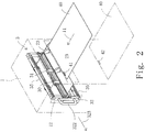
- the support frame 32 can pass through an opening 12 formed in the side wall of the housing 1 ( Figs. 2 and 3 ).
- the guide mechanism 35 comprises an upper and lower horizontal telescopic arms which are actuated perpendicularly to the feed direction 11.
- Each of the telescopic arms 35 comprises a first fixed rail 351 mounted on the horizontal member 320 of the support frame 32, a second fixed rail 352 mounted on the housing 1, and a slider 350 attached to the first and second fixed rails 351, 352.
- the slider 350 can slide along the first and second fixed rails 351, 352.
- Each of the telescopic arms 35 can be contracted by superimposing the first and second fixed rails 351, 352 and sliders 350 ( Fig. 2 ), on the other hand, it can be expanded by drawing the support frame 32 out of housing 1 and sliding the slider 350 along the first and second fixed rails 351, 352 ( Fig. 3 ).
- a handle 322 is mounted on the support frame 32 in such a manner that the support frame 32 can be easily moved into and out of the housing 1.
- the support frame 32 has attachments 36, 37.
- the attachments 36, 37 are configured to detachably attach the guide rail 33 to the support frame 32.
- the attachment 36 comprises a pair of upper portions 36
- the attachment 37 comprises a pair of lower portions 37.
- the upper and lower portions 36, 37 are disposed on the vertical members 321 of the support frame 32.
- the upper portion 36 is spaced from the lower portion 37 at a predetermined interval.
- the upper and lower portions 36, 37 is pin-shaped and projects toward the front side of the support frame 32.
- the guide rail 33 has a pair of holes 330 at both ends thereof for inserting the upper or lower portion 36, 37.
- the reflective arm 34 has a pair of holes 340 at both ends thereof for inserting the upper or lower portion 36, 37.
- the guide rail 33 and the reflective arm 34 are attached to the support frame 32 in such a manner that the holes 330, 340 can be inserted into and removed from the upper and lower portions 36, 37.
- the guide rail 33 and the reflective arm 34 can be detachably attached to the support frame 32 easily.
- the guide rail 33 and the reflective arm 34 are removed from the support frame 32 ( Fig. 5A ).
- the guide rail 33 is disposed on the lower side of the support frame 32 in such a manner that the light emitted from the detectors 30, 31 can be toward the upper side.
- the reflective arm 34 is disposed on the upper side of the support frame 32 so as to reflect the light emitted from the detectors 30, 31.
- the guide rail 33 is attached to the lower side of the support frame 32, and the reflective arm 34 is attached to the upper side of the support frame 32 ( Fig. 5B ). In this operation, an operator can draw the support frame 32 out of the housing 1 so as to easily change the positional relation of the guide rail 33 and the reflective arm 34.
- the guide mechanism 35 comprises the telescopic arms having the first and second fixed rails 351, 352 and sliders 350
- another means may be used as the guide mechanism 35.
- the another means may comprise the first fixed rails 351 mounted on the support frame 32 and the second fixed rails 352 mounted on the housing 1, and the first and second rails 351, 352 are engaged with each other for slide movement.
- the detectors 30, 31 emits light toward the marks 41, 42
- the constructions of the detectors 30, 31 are not limited to this embodiment.
- the information is a bar-code
- bar-code readers should be used as the detectors 30, 31.
- CCD cameras may be used as the detectors 30, 31. If only one of the front and last page should be detected, a single detector is used for detecting information.
- the attachments 36, 37 comprise the pin-shape members 36, 37 and the holes 330, 340
- another means may be used.
- a velvet fastener, a combination of bolt and nut and so on can be used as the attachments 36,37.
Landscapes
- Engineering & Computer Science (AREA)
- Mechanical Engineering (AREA)
- Controlling Sheets Or Webs (AREA)
- Sheets, Magazines, And Separation Thereof (AREA)
Claims (6)
- Dispositif d'alimentation papier, comprenant :un logement (1) ;une section d'alimentation (2) pour alimenter une pluralité de feuilles (40) placée sur un bac à feuilles dans un sens d'alimentation (11) ; etune section de détection (3) comportant au moins un détecteur (30, 31) pour détecter des informations imprimées sur la feuille (40),caractérisé en ce que la section de détection (3) comprend:un châssis de support (32) pour supporter le détecteur (30, 31) ;un rail de guidage horizontal (33) monté sur le châssis de support (32) et s'étendant perpendiculairement au sens d'alimentation (11) de manière à guider le détecteur (30, 31) ; etun mécanisme de guidage (35) agencé entre le logement (1) et le châssis de support (32) pour guider le châssis de support (32) de manière à ce que le châssis de support (32) entre dans le logement (1) et en sorte perpendiculairement au sens d'alimentation (11) et dans le sens horizontal, et dans lequelle châssis de support (32) est reçu dans le logement (1) quand le détecteur (30, 31) détecte la feuille (40) alimentée depuis la section d'alimentation (2), etle châssis de support (32) est retiré du logement (1) quand le détecteur (30, 31) est déplacé le long du rail de guidage (33).
- Dispositif selon la revendication 1, dans lequel le châssis de support (32) comprend :une paire d'éléments horizontaux (320) agencés parallèlement l'un à l'autre ; etune paire d'éléments verticaux (321) agencés parallèlement l'un à l'autre et s'étendant entre les éléments horizontaux (320), dans lequelle mécanisme de guidage (35) comprend :une paire de bras télescopiques horizontaux (35) qui est actionnée perpendiculairement au sens d'alimentation (11), les bras télescopiques (35) étant attachés au logement (1) à une de leurs extrémités et attachés au châssis de support (32) à leur autre extrémité, et dans lequel chacun des bras télescopiques (35) est attaché aux éléments horizontaux (320) du châssis de support (32).
- Dispositif selon la revendication 1 ou 2, comprenant en outre :des attaches (36, 37) pour attacher de manière amovible le rail de guidage (33) sur le châssis de support (32), dans lequelles attaches (36, 37) comprennent :une partie supérieure (36) disposée sur le châssis de support (32) au-dessus de la feuille (40) alimentée depuis la section d'alimentation (2) de manière à attacher de manière amovible le rail de guidage (33) ; etune partie inférieure (37) disposée sur le châssis de support (32) en dessous de la feuille (40) alimentée depuis la section d'alimentation (2) de manière à attacher de manière amovible le rail de guidage (33) ; et dans lequelle détecteur (30, 31) détecte les informations (41, 42) imprimées sur un côté supérieur de la feuille (40) pendant que le rail de guidage (33) est attaché à la partie supérieure (36),le détecteur (30, 31) détecte les informations (41, 42) imprimées sur un côté inférieur de la feuille (40) pendant que le rail de guidage (33) est attaché à la partie inférieure (37).
- Dispositif selon la revendication 3, comprenant en outre :un bras réflecteur (34) pour réfléchir la lumière émise par le détecteur (30, 31), et dans lequelle bras réflecteur (34) est attaché de manière amovible aux parties supérieure (36) et inférieure (37) des attaches (36, 37) de telle sorte que le bras réflecteur (34) s'étende parallèlement au rail de guidage (33) quand le bras réflecteur (34) est attaché au châssis de support (32).
- Dispositif selon la revendication 3, dans lequel
chacune des parties supérieure (36) et inférieure (37) des attaches (36, 37) est en forme de goupille et fait saillie depuis le châssis de support (32) de manière à être insérée dans un orifice (330) formé sur le rail de guidage (33) et à en être extraite. - Dispositif selon la revendication 4, dans lequel
le bras réflecteur (34) comporte une échelle pour confirmer une position exacte du détecteur (30, 31).
Applications Claiming Priority (1)
| Application Number | Priority Date | Filing Date | Title |
|---|---|---|---|
| PCT/JP2011/071880 WO2013046295A1 (fr) | 2011-09-26 | 2011-09-26 | Dispositif d'alimentation papier |
Publications (3)
| Publication Number | Publication Date |
|---|---|
| EP2657164A1 EP2657164A1 (fr) | 2013-10-30 |
| EP2657164A4 EP2657164A4 (fr) | 2015-03-11 |
| EP2657164B1 true EP2657164B1 (fr) | 2016-05-25 |
Family
ID=47994414
Family Applications (1)
| Application Number | Title | Priority Date | Filing Date |
|---|---|---|---|
| EP11873155.3A Active EP2657164B1 (fr) | 2011-09-26 | 2011-09-26 | Dispositif d'alimentation papier |
Country Status (6)
| Country | Link |
|---|---|
| US (1) | US8833764B2 (fr) |
| EP (1) | EP2657164B1 (fr) |
| JP (1) | JP5761830B2 (fr) |
| CN (1) | CN103313923B (fr) |
| DK (1) | DK2657164T3 (fr) |
| WO (1) | WO2013046295A1 (fr) |
Families Citing this family (4)
| Publication number | Priority date | Publication date | Assignee | Title |
|---|---|---|---|---|
| CN104284853B (zh) * | 2012-07-06 | 2016-08-17 | 好利用国际株式会社 | 供纸装置 |
| JP6218595B2 (ja) * | 2013-12-25 | 2017-10-25 | キヤノン株式会社 | シート処理装置及び画像形成装置 |
| CN106219276A (zh) * | 2016-08-05 | 2016-12-14 | 广东新宏泽包装股份有限公司 | 自动检测印刷纸张的输纸设备及检测方法 |
| TWI716289B (zh) * | 2020-02-27 | 2021-01-11 | 康卓林機械股份有限公司 | 紙張側拉對位裝置 |
Family Cites Families (18)
| Publication number | Priority date | Publication date | Assignee | Title |
|---|---|---|---|---|
| GB638924A (en) * | 1947-08-05 | 1950-06-21 | Headley Townsend Backhouse | Improvements in or relating to front edge detector mechanism for use in sheet feeding apparatus |
| JPS55135052A (en) * | 1979-04-04 | 1980-10-21 | Toshiyo Insatsu Kk | Method and device for detecting missing leaves and surplus leaves in binding calender |
| US5166536A (en) * | 1991-02-11 | 1992-11-24 | Rye Timothy W | Method and apparatus for detecting edge cracks |
| US5260583A (en) * | 1991-02-11 | 1993-11-09 | Rye Timothy W | Method and apparatus for detecting edge cracks |
| KR0171545B1 (ko) * | 1996-01-12 | 1999-05-01 | 김광호 | 용지길이 자동검출에 의한 프린팅 시스템 및 그 제어방법 |
| US6255665B1 (en) * | 1999-01-29 | 2001-07-03 | Hewlett-Packard Company | Print media and method of detecting a characteristic of a substrate of print media used in a printing device |
| WO2000058104A1 (fr) * | 1999-03-26 | 2000-10-05 | Datamax Corporation | Imprimante modulaire |
| US6439563B1 (en) * | 2000-01-18 | 2002-08-27 | Currency Systems International, Inc. | Note feeder |
| JP2002067408A (ja) * | 2000-08-31 | 2002-03-05 | Sato Corp | ポータブルプリンタ |
| JP3746769B2 (ja) * | 2003-02-24 | 2006-02-15 | 新光電子株式会社 | 物品の寸法測定装置 |
| JP4467359B2 (ja) | 2003-05-28 | 2010-05-26 | ニスカ株式会社 | 画像読取装置 |
| US20050006285A1 (en) * | 2003-07-10 | 2005-01-13 | Kabushiki Kaisha Toshiba | Sheet discriminator, sheet discriminating method and sheet discriminating threshold value deciding method |
| JP4261308B2 (ja) | 2003-10-16 | 2009-04-30 | ホリゾン・インターナショナル株式会社 | 給紙装置 |
| JP4500746B2 (ja) * | 2005-08-29 | 2010-07-14 | 株式会社リコー | 穿孔処理装置、シート処理装置および画像形成装置 |
| JP4891608B2 (ja) | 2005-12-19 | 2012-03-07 | 三菱重工印刷紙工機械株式会社 | 印刷機の断裁制御装置及び断裁制御方法 |
| JP2007284158A (ja) * | 2006-04-13 | 2007-11-01 | Horizon International Inc | 針金綴機 |
| JP5623161B2 (ja) * | 2010-06-30 | 2014-11-12 | キヤノン株式会社 | 画像形成装置 |
| CA2852928A1 (fr) * | 2011-10-20 | 2013-04-25 | Source Technologies, Llc | Capteur de debut de page |
-
2011
- 2011-09-26 WO PCT/JP2011/071880 patent/WO2013046295A1/fr not_active Ceased
- 2011-09-26 DK DK11873155.3T patent/DK2657164T3/en active
- 2011-09-26 JP JP2013535656A patent/JP5761830B2/ja active Active
- 2011-09-26 EP EP11873155.3A patent/EP2657164B1/fr active Active
- 2011-09-26 CN CN201180064763.7A patent/CN103313923B/zh active Active
- 2011-09-26 US US13/976,270 patent/US8833764B2/en active Active
Also Published As
| Publication number | Publication date |
|---|---|
| EP2657164A4 (fr) | 2015-03-11 |
| DK2657164T3 (en) | 2016-08-22 |
| JPWO2013046295A1 (ja) | 2015-03-26 |
| CN103313923B (zh) | 2016-04-20 |
| US20130270766A1 (en) | 2013-10-17 |
| EP2657164A1 (fr) | 2013-10-30 |
| WO2013046295A1 (fr) | 2013-04-04 |
| US8833764B2 (en) | 2014-09-16 |
| CN103313923A (zh) | 2013-09-18 |
| JP5761830B2 (ja) | 2015-08-12 |
Similar Documents
| Publication | Publication Date | Title |
|---|---|---|
| US7694960B2 (en) | Media size sensing system and method | |
| DK2871146T3 (en) | Sheet feeder | |
| EP2657164B1 (fr) | Dispositif d'alimentation papier | |
| US20150151944A1 (en) | Post-processing device and image forming system including this post-processing device | |
| US9857748B2 (en) | Sheet supporting device | |
| EP2947863B1 (fr) | Appareil de lecture d'image et appareil multifonction doté de celui-ci | |
| US10053309B2 (en) | Sheet tray | |
| US20060255531A1 (en) | Automatic printer stack edge guide alignment information | |
| JP2016023031A (ja) | シート供給装置およびプリント装置 | |
| JP5825280B2 (ja) | 後処理装置および画像形成システム | |
| CN100488858C (zh) | 立式配页机 | |
| EP4082949B1 (fr) | Dispositif porteur de platine | |
| EP1640170A1 (fr) | Plateau pour montage d'un élement de type plaque fine, et appareil d'enregistrement | |
| JP4518171B2 (ja) | 用紙処理装置 | |
| US10272588B2 (en) | Sheet processing apparatus | |
| JP6507370B2 (ja) | 部品供給装置および部品装着装置ならびに部品検出センサ | |
| JP2006056681A (ja) | 手差し給紙装置及び画像形成装置 | |
| RU2774855C2 (ru) | Аппарат считывания изображения | |
| EP4082950A1 (fr) | Dispositif de transport de plaque | |
| JP2006311052A (ja) | 自動原稿送り装置 | |
| JP2004231410A (ja) | 手差しトレイユニット | |
| JP2021084745A (ja) | 媒体搬送装置及び処理装置 | |
| EP1971124A2 (fr) | Moyens de support de feuille originale dans un scanner | |
| JP2008114973A (ja) | 用紙ガイド装置 | |
| JPS6144789B2 (fr) |
Legal Events
| Date | Code | Title | Description |
|---|---|---|---|
| PUAI | Public reference made under article 153(3) epc to a published international application that has entered the european phase |
Free format text: ORIGINAL CODE: 0009012 |
|
| 17P | Request for examination filed |
Effective date: 20130722 |
|
| AK | Designated contracting states |
Kind code of ref document: A1 Designated state(s): AL AT BE BG CH CY CZ DE DK EE ES FI FR GB GR HR HU IE IS IT LI LT LU LV MC MK MT NL NO PL PT RO RS SE SI SK SM TR |
|
| RIN1 | Information on inventor provided before grant (corrected) |
Inventor name: MOCHIZUKI, JUN Inventor name: KASHIBA, MASAYUKI Inventor name: ONODERA, AKIRA |
|
| DAX | Request for extension of the european patent (deleted) | ||
| A4 | Supplementary search report drawn up and despatched |
Effective date: 20150206 |
|
| RIC1 | Information provided on ipc code assigned before grant |
Ipc: B65H 7/06 20060101ALI20150202BHEP Ipc: B42C 1/12 20060101ALN20150202BHEP Ipc: B65H 5/06 20060101AFI20150202BHEP Ipc: B65H 7/14 20060101ALI20150202BHEP |
|
| REG | Reference to a national code |
Ref country code: DE Ref legal event code: R079 Ref document number: 602011027014 Country of ref document: DE Free format text: PREVIOUS MAIN CLASS: B65H0007020000 Ipc: B65H0005060000 |
|
| GRAP | Despatch of communication of intention to grant a patent |
Free format text: ORIGINAL CODE: EPIDOSNIGR1 |
|
| RIC1 | Information provided on ipc code assigned before grant |
Ipc: B65H 7/14 20060101ALI20150925BHEP Ipc: B42C 1/12 20060101ALN20150925BHEP Ipc: B65H 7/06 20060101ALI20150925BHEP Ipc: B65H 5/06 20060101AFI20150925BHEP |
|
| INTG | Intention to grant announced |
Effective date: 20151104 |
|
| GRAS | Grant fee paid |
Free format text: ORIGINAL CODE: EPIDOSNIGR3 |
|
| GRAA | (expected) grant |
Free format text: ORIGINAL CODE: 0009210 |
|
| AK | Designated contracting states |
Kind code of ref document: B1 Designated state(s): AL AT BE BG CH CY CZ DE DK EE ES FI FR GB GR HR HU IE IS IT LI LT LU LV MC MK MT NL NO PL PT RO RS SE SI SK SM TR |
|
| REG | Reference to a national code |
Ref country code: GB Ref legal event code: FG4D |
|
| REG | Reference to a national code |
Ref country code: CH Ref legal event code: EP |
|
| REG | Reference to a national code |
Ref country code: IE Ref legal event code: FG4D Ref country code: AT Ref legal event code: REF Ref document number: 802114 Country of ref document: AT Kind code of ref document: T Effective date: 20160615 |
|
| REG | Reference to a national code |
Ref country code: DE Ref legal event code: R096 Ref document number: 602011027014 Country of ref document: DE |
|
| REG | Reference to a national code |
Ref country code: CH Ref legal event code: NV Representative=s name: SERVOPATENT GMBH, CH |
|
| REG | Reference to a national code |
Ref country code: SE Ref legal event code: TRGR |
|
| REG | Reference to a national code |
Ref country code: DK Ref legal event code: T3 Effective date: 20160818 |
|
| REG | Reference to a national code |
Ref country code: FR Ref legal event code: PLFP Year of fee payment: 6 |
|
| REG | Reference to a national code |
Ref country code: LT Ref legal event code: MG4D |
|
| REG | Reference to a national code |
Ref country code: NL Ref legal event code: MP Effective date: 20160525 |
|
| PG25 | Lapsed in a contracting state [announced via postgrant information from national office to epo] |
Ref country code: LT Free format text: LAPSE BECAUSE OF FAILURE TO SUBMIT A TRANSLATION OF THE DESCRIPTION OR TO PAY THE FEE WITHIN THE PRESCRIBED TIME-LIMIT Effective date: 20160525 Ref country code: FI Free format text: LAPSE BECAUSE OF FAILURE TO SUBMIT A TRANSLATION OF THE DESCRIPTION OR TO PAY THE FEE WITHIN THE PRESCRIBED TIME-LIMIT Effective date: 20160525 Ref country code: NO Free format text: LAPSE BECAUSE OF FAILURE TO SUBMIT A TRANSLATION OF THE DESCRIPTION OR TO PAY THE FEE WITHIN THE PRESCRIBED TIME-LIMIT Effective date: 20160825 Ref country code: NL Free format text: LAPSE BECAUSE OF FAILURE TO SUBMIT A TRANSLATION OF THE DESCRIPTION OR TO PAY THE FEE WITHIN THE PRESCRIBED TIME-LIMIT Effective date: 20160525 |
|
| PGFP | Annual fee paid to national office [announced via postgrant information from national office to epo] |
Ref country code: DK Payment date: 20160920 Year of fee payment: 6 |
|
| REG | Reference to a national code |
Ref country code: AT Ref legal event code: MK05 Ref document number: 802114 Country of ref document: AT Kind code of ref document: T Effective date: 20160525 |
|
| PG25 | Lapsed in a contracting state [announced via postgrant information from national office to epo] |
Ref country code: GR Free format text: LAPSE BECAUSE OF FAILURE TO SUBMIT A TRANSLATION OF THE DESCRIPTION OR TO PAY THE FEE WITHIN THE PRESCRIBED TIME-LIMIT Effective date: 20160826 Ref country code: RS Free format text: LAPSE BECAUSE OF FAILURE TO SUBMIT A TRANSLATION OF THE DESCRIPTION OR TO PAY THE FEE WITHIN THE PRESCRIBED TIME-LIMIT Effective date: 20160525 Ref country code: LV Free format text: LAPSE BECAUSE OF FAILURE TO SUBMIT A TRANSLATION OF THE DESCRIPTION OR TO PAY THE FEE WITHIN THE PRESCRIBED TIME-LIMIT Effective date: 20160525 Ref country code: ES Free format text: LAPSE BECAUSE OF FAILURE TO SUBMIT A TRANSLATION OF THE DESCRIPTION OR TO PAY THE FEE WITHIN THE PRESCRIBED TIME-LIMIT Effective date: 20160525 Ref country code: PT Free format text: LAPSE BECAUSE OF FAILURE TO SUBMIT A TRANSLATION OF THE DESCRIPTION OR TO PAY THE FEE WITHIN THE PRESCRIBED TIME-LIMIT Effective date: 20160926 |
|
| PG25 | Lapsed in a contracting state [announced via postgrant information from national office to epo] |
Ref country code: EE Free format text: LAPSE BECAUSE OF FAILURE TO SUBMIT A TRANSLATION OF THE DESCRIPTION OR TO PAY THE FEE WITHIN THE PRESCRIBED TIME-LIMIT Effective date: 20160525 Ref country code: SK Free format text: LAPSE BECAUSE OF FAILURE TO SUBMIT A TRANSLATION OF THE DESCRIPTION OR TO PAY THE FEE WITHIN THE PRESCRIBED TIME-LIMIT Effective date: 20160525 Ref country code: RO Free format text: LAPSE BECAUSE OF FAILURE TO SUBMIT A TRANSLATION OF THE DESCRIPTION OR TO PAY THE FEE WITHIN THE PRESCRIBED TIME-LIMIT Effective date: 20160525 Ref country code: CZ Free format text: LAPSE BECAUSE OF FAILURE TO SUBMIT A TRANSLATION OF THE DESCRIPTION OR TO PAY THE FEE WITHIN THE PRESCRIBED TIME-LIMIT Effective date: 20160525 |
|
| PG25 | Lapsed in a contracting state [announced via postgrant information from national office to epo] |
Ref country code: PL Free format text: LAPSE BECAUSE OF FAILURE TO SUBMIT A TRANSLATION OF THE DESCRIPTION OR TO PAY THE FEE WITHIN THE PRESCRIBED TIME-LIMIT Effective date: 20160525 Ref country code: AT Free format text: LAPSE BECAUSE OF FAILURE TO SUBMIT A TRANSLATION OF THE DESCRIPTION OR TO PAY THE FEE WITHIN THE PRESCRIBED TIME-LIMIT Effective date: 20160525 Ref country code: SM Free format text: LAPSE BECAUSE OF FAILURE TO SUBMIT A TRANSLATION OF THE DESCRIPTION OR TO PAY THE FEE WITHIN THE PRESCRIBED TIME-LIMIT Effective date: 20160525 |
|
| REG | Reference to a national code |
Ref country code: DE Ref legal event code: R097 Ref document number: 602011027014 Country of ref document: DE |
|
| PLBE | No opposition filed within time limit |
Free format text: ORIGINAL CODE: 0009261 |
|
| STAA | Information on the status of an ep patent application or granted ep patent |
Free format text: STATUS: NO OPPOSITION FILED WITHIN TIME LIMIT |
|
| PG25 | Lapsed in a contracting state [announced via postgrant information from national office to epo] |
Ref country code: MC Free format text: LAPSE BECAUSE OF FAILURE TO SUBMIT A TRANSLATION OF THE DESCRIPTION OR TO PAY THE FEE WITHIN THE PRESCRIBED TIME-LIMIT Effective date: 20160525 |
|
| 26N | No opposition filed |
Effective date: 20170228 |
|
| PG25 | Lapsed in a contracting state [announced via postgrant information from national office to epo] |
Ref country code: SI Free format text: LAPSE BECAUSE OF FAILURE TO SUBMIT A TRANSLATION OF THE DESCRIPTION OR TO PAY THE FEE WITHIN THE PRESCRIBED TIME-LIMIT Effective date: 20160525 |
|
| REG | Reference to a national code |
Ref country code: IE Ref legal event code: MM4A |
|
| PG25 | Lapsed in a contracting state [announced via postgrant information from national office to epo] |
Ref country code: IE Free format text: LAPSE BECAUSE OF NON-PAYMENT OF DUE FEES Effective date: 20160926 |
|
| PG25 | Lapsed in a contracting state [announced via postgrant information from national office to epo] |
Ref country code: LU Free format text: LAPSE BECAUSE OF NON-PAYMENT OF DUE FEES Effective date: 20160926 |
|
| REG | Reference to a national code |
Ref country code: FR Ref legal event code: PLFP Year of fee payment: 7 |
|
| REG | Reference to a national code |
Ref country code: DK Ref legal event code: EBP Effective date: 20170930 |
|
| PG25 | Lapsed in a contracting state [announced via postgrant information from national office to epo] |
Ref country code: HU Free format text: LAPSE BECAUSE OF FAILURE TO SUBMIT A TRANSLATION OF THE DESCRIPTION OR TO PAY THE FEE WITHIN THE PRESCRIBED TIME-LIMIT; INVALID AB INITIO Effective date: 20110926 Ref country code: CY Free format text: LAPSE BECAUSE OF FAILURE TO SUBMIT A TRANSLATION OF THE DESCRIPTION OR TO PAY THE FEE WITHIN THE PRESCRIBED TIME-LIMIT Effective date: 20160525 |
|
| PG25 | Lapsed in a contracting state [announced via postgrant information from national office to epo] |
Ref country code: MK Free format text: LAPSE BECAUSE OF FAILURE TO SUBMIT A TRANSLATION OF THE DESCRIPTION OR TO PAY THE FEE WITHIN THE PRESCRIBED TIME-LIMIT Effective date: 20160525 Ref country code: IS Free format text: LAPSE BECAUSE OF FAILURE TO SUBMIT A TRANSLATION OF THE DESCRIPTION OR TO PAY THE FEE WITHIN THE PRESCRIBED TIME-LIMIT Effective date: 20160525 Ref country code: TR Free format text: LAPSE BECAUSE OF FAILURE TO SUBMIT A TRANSLATION OF THE DESCRIPTION OR TO PAY THE FEE WITHIN THE PRESCRIBED TIME-LIMIT Effective date: 20160525 Ref country code: MT Free format text: LAPSE BECAUSE OF NON-PAYMENT OF DUE FEES Effective date: 20160930 Ref country code: HR Free format text: LAPSE BECAUSE OF FAILURE TO SUBMIT A TRANSLATION OF THE DESCRIPTION OR TO PAY THE FEE WITHIN THE PRESCRIBED TIME-LIMIT Effective date: 20160525 |
|
| PG25 | Lapsed in a contracting state [announced via postgrant information from national office to epo] |
Ref country code: BG Free format text: LAPSE BECAUSE OF FAILURE TO SUBMIT A TRANSLATION OF THE DESCRIPTION OR TO PAY THE FEE WITHIN THE PRESCRIBED TIME-LIMIT Effective date: 20160525 |
|
| REG | Reference to a national code |
Ref country code: FR Ref legal event code: PLFP Year of fee payment: 8 |
|
| PG25 | Lapsed in a contracting state [announced via postgrant information from national office to epo] |
Ref country code: AL Free format text: LAPSE BECAUSE OF FAILURE TO SUBMIT A TRANSLATION OF THE DESCRIPTION OR TO PAY THE FEE WITHIN THE PRESCRIBED TIME-LIMIT Effective date: 20160525 |
|
| PG25 | Lapsed in a contracting state [announced via postgrant information from national office to epo] |
Ref country code: DK Free format text: LAPSE BECAUSE OF NON-PAYMENT OF DUE FEES Effective date: 20170930 |
|
| REG | Reference to a national code |
Ref country code: CH Ref legal event code: PCAR Free format text: NEW ADDRESS: WANNERSTRASSE 9/1, 8045 ZUERICH (CH) |
|
| PGFP | Annual fee paid to national office [announced via postgrant information from national office to epo] |
Ref country code: BE Payment date: 20200925 Year of fee payment: 10 Ref country code: SE Payment date: 20200925 Year of fee payment: 10 Ref country code: IT Payment date: 20200922 Year of fee payment: 10 Ref country code: CH Payment date: 20200921 Year of fee payment: 10 |
|
| REG | Reference to a national code |
Ref country code: CH Ref legal event code: PL |
|
| REG | Reference to a national code |
Ref country code: SE Ref legal event code: EUG |
|
| REG | Reference to a national code |
Ref country code: BE Ref legal event code: MM Effective date: 20210930 |
|
| PG25 | Lapsed in a contracting state [announced via postgrant information from national office to epo] |
Ref country code: SE Free format text: LAPSE BECAUSE OF NON-PAYMENT OF DUE FEES Effective date: 20210927 Ref country code: BE Free format text: LAPSE BECAUSE OF NON-PAYMENT OF DUE FEES Effective date: 20210930 |
|
| PG25 | Lapsed in a contracting state [announced via postgrant information from national office to epo] |
Ref country code: LI Free format text: LAPSE BECAUSE OF NON-PAYMENT OF DUE FEES Effective date: 20210930 Ref country code: CH Free format text: LAPSE BECAUSE OF NON-PAYMENT OF DUE FEES Effective date: 20210930 |
|
| PG25 | Lapsed in a contracting state [announced via postgrant information from national office to epo] |
Ref country code: IT Free format text: LAPSE BECAUSE OF NON-PAYMENT OF DUE FEES Effective date: 20210926 |
|
| PGFP | Annual fee paid to national office [announced via postgrant information from national office to epo] |
Ref country code: DE Payment date: 20250919 Year of fee payment: 15 |
|
| PGFP | Annual fee paid to national office [announced via postgrant information from national office to epo] |
Ref country code: GB Payment date: 20250918 Year of fee payment: 15 |
|
| PGFP | Annual fee paid to national office [announced via postgrant information from national office to epo] |
Ref country code: FR Payment date: 20250922 Year of fee payment: 15 |