EP2657454A1 - Structure de diaphragme de turbine - Google Patents
Structure de diaphragme de turbine Download PDFInfo
- Publication number
- EP2657454A1 EP2657454A1 EP12165618.5A EP12165618A EP2657454A1 EP 2657454 A1 EP2657454 A1 EP 2657454A1 EP 12165618 A EP12165618 A EP 12165618A EP 2657454 A1 EP2657454 A1 EP 2657454A1
- Authority
- EP
- European Patent Office
- Prior art keywords
- diaphragm
- ring
- radially
- segments
- platform portions
- Prior art date
- Legal status (The legal status is an assumption and is not a legal conclusion. Google has not performed a legal analysis and makes no representation as to the accuracy of the status listed.)
- Granted
Links
Images
Classifications
-
- F—MECHANICAL ENGINEERING; LIGHTING; HEATING; WEAPONS; BLASTING
- F01—MACHINES OR ENGINES IN GENERAL; ENGINE PLANTS IN GENERAL; STEAM ENGINES
- F01D—NON-POSITIVE DISPLACEMENT MACHINES OR ENGINES, e.g. STEAM TURBINES
- F01D9/00—Stators
- F01D9/02—Nozzles; Nozzle boxes; Stator blades; Guide conduits, e.g. individual nozzles
- F01D9/04—Nozzles; Nozzle boxes; Stator blades; Guide conduits, e.g. individual nozzles forming ring or sector
- F01D9/042—Nozzles; Nozzle boxes; Stator blades; Guide conduits, e.g. individual nozzles forming ring or sector fixing blades to stators
-
- F—MECHANICAL ENGINEERING; LIGHTING; HEATING; WEAPONS; BLASTING
- F01—MACHINES OR ENGINES IN GENERAL; ENGINE PLANTS IN GENERAL; STEAM ENGINES
- F01D—NON-POSITIVE DISPLACEMENT MACHINES OR ENGINES, e.g. STEAM TURBINES
- F01D25/00—Component parts, details, or accessories, not provided for in, or of interest apart from, other groups
- F01D25/24—Casings; Casing parts, e.g. diaphragms, casing fastenings
- F01D25/246—Fastening of diaphragms or stator-rings
-
- F—MECHANICAL ENGINEERING; LIGHTING; HEATING; WEAPONS; BLASTING
- F05—INDEXING SCHEMES RELATING TO ENGINES OR PUMPS IN VARIOUS SUBCLASSES OF CLASSES F01-F04
- F05D—INDEXING SCHEME FOR ASPECTS RELATING TO NON-POSITIVE-DISPLACEMENT MACHINES OR ENGINES, GAS-TURBINES OR JET-PROPULSION PLANTS
- F05D2220/00—Application
- F05D2220/30—Application in turbines
- F05D2220/31—Application in turbines in steam turbines
-
- F—MECHANICAL ENGINEERING; LIGHTING; HEATING; WEAPONS; BLASTING
- F05—INDEXING SCHEMES RELATING TO ENGINES OR PUMPS IN VARIOUS SUBCLASSES OF CLASSES F01-F04
- F05D—INDEXING SCHEME FOR ASPECTS RELATING TO NON-POSITIVE-DISPLACEMENT MACHINES OR ENGINES, GAS-TURBINES OR JET-PROPULSION PLANTS
- F05D2240/00—Components
- F05D2240/80—Platforms for stationary or moving blades
-
- F—MECHANICAL ENGINEERING; LIGHTING; HEATING; WEAPONS; BLASTING
- F05—INDEXING SCHEMES RELATING TO ENGINES OR PUMPS IN VARIOUS SUBCLASSES OF CLASSES F01-F04
- F05D—INDEXING SCHEME FOR ASPECTS RELATING TO NON-POSITIVE-DISPLACEMENT MACHINES OR ENGINES, GAS-TURBINES OR JET-PROPULSION PLANTS
- F05D2250/00—Geometry
- F05D2250/30—Arrangement of components
- F05D2250/31—Arrangement of components according to the direction of their main axis or their axis of rotation
- F05D2250/314—Arrangement of components according to the direction of their main axis or their axis of rotation the axes being inclined in relation to each other
-
- Y—GENERAL TAGGING OF NEW TECHNOLOGICAL DEVELOPMENTS; GENERAL TAGGING OF CROSS-SECTIONAL TECHNOLOGIES SPANNING OVER SEVERAL SECTIONS OF THE IPC; TECHNICAL SUBJECTS COVERED BY FORMER USPC CROSS-REFERENCE ART COLLECTIONS [XRACs] AND DIGESTS
- Y10—TECHNICAL SUBJECTS COVERED BY FORMER USPC
- Y10T—TECHNICAL SUBJECTS COVERED BY FORMER US CLASSIFICATION
- Y10T29/00—Metal working
- Y10T29/49—Method of mechanical manufacture
- Y10T29/49229—Prime mover or fluid pump making
- Y10T29/49236—Fluid pump or compressor making
Definitions
- This disclosure relates to the construction of diaphragms for turbines, and in particular, to a novel structure and assembly process for diaphragms in axial flow steam turbines.
- a known way of constructing a steam turbine diaphragm is to mount an annulus of static guide blades between an inner ring and an outer ring.
- Each such blade comprises a blade unit in which an aerofoil portion extends between an inner platform and an outer platform, the blade unit being machined as a single component.
- This is known as the "platform" type of construction.
- Each platform is in the form of a segment of a cylinder so that when the annulus of blade units is assembled, the inner platforms combine to create an inner port wall and the outer platforms combine to create an outer port wall.
- the inner platforms are welded to an inner ring that retains the turbine blades and provides a mount for a sealing arrangement, such as a labyrinth seal, that acts between the inner ring and a rotor shaft of the turbine.
- the outer platforms are welded to an outer ring that provides support and rigidity to the diaphragm.
- Each of the inner and outer rings comprises two semi-circular halves which are joined along a plane that contains the major axis of the diaphragm and passes between blade units so that the entire diaphragm can be separated into two parts for assembly around the rotor of the turbomachine.
- Existing platform constructions for HP or IP steam turbine diaphragms generally comprise solid inner and outer rings cut from thick metal plate, or forged, or formed from bar stock. Since such rings in large turbines have substantial dimensions in the axial and radial directions of the turbine, e.g., 100mm to 200mm, the cost of welding together the components of the diaphragm is a significant factor in the ex-works price of a large steam turbine, not least because the necessary deep penetration welds require advanced specialist welding equipment for their production. Furthermore, welds are a possible source of metallurgical defects in the diaphragm and it is also necessary to heat treat the diaphragm in order to relieve stresses in the diaphragm caused by the welding processes.
- an axial flow turbine diaphragm comprising:
- the radially outer diaphragm ring includes the radially outer platform portions of the blade units as part of its structure.
- the present concept produces a diaphragm structure in which a radially outer port wall of the diaphragm comprises the radially outer platform portions, alternating in the circumferential direction with exposed portions of the inner circumference of the outer diaphragm ring.
- the above construction enables the components of the diaphragm to be assembled and held together solely by mechanical means, i.e., the diaphragm can be constructed without welding or other metal melting techniques.
- the radially inner platform portions of the blade units are elongate in the circumferential direction of the turbine diaphragm and an outer circumference of the radially inner ring is provided with a blade unit retaining feature of complementary shape and orientation to the inner platform portions of the static blade units, whereby the inner platform portions are retained to the radially inner ring.
- the radially inner diaphragm ring includes the radially inner platform portions of the blade units as part of its structure.
- the radially inner port wall of the diaphragm will comprise the radially inner platform portions, flanked on their axially opposed (inlet and outlet) sides by exposed portions of the outer circumference of the inner diaphragm ring.
- the preferred construction enables the components of the diaphragm to be assembled and held together solely by mechanical interlocking of its components.
- confronting ends of the radially inner elongate platform portions should preferably butt up to each other when inserted into the blade unit retaining feature of the inner ring, such that the platform portions extend continuously around the inner port wall of the diaphragm in the circumferential direction.
- the platform portions of the blade units and the blade retaining features of the inner and outer rings should be accurately manufactured and closely matched to each other, so that the inner and outer port walls of the diaphragm are sufficiently smooth to avoid excessive aerodynamic drag penalties.
- the radially inner platform portions and the radially outer platform portions of the blade units have radial cross-sections shaped to fit blade unit retaining features in the form of slots or grooves having radial cross-sections with undercut or re-entrant shapes, such as dovetails.
- the radially inner and outer platform portions of the blade units are T-shaped in cross-section; for the inner platform portions the cross-bar of the T-shape is positioned radially inwards of the stem of the T-shape, whereas for the outer platform portions, the cross-bar of the T-shape is positioned radially outwards of the stem of the T-shape.
- the radially inner and outer diaphragm rings may each comprise at least two segments.
- the inner diaphragm ring has an even number of segments comprising at least four segments and the outer diaphragm ring is preferably constructed as two segments that upon assembly are united with each other on joint planes at diametrically opposed sides of the outer diaphragm ring.
- the joint planes are pitched at a scarf angle that is the same or closely similar to the stagger angle of the aerofoils.
- the segments of the outer diaphragm ring may be united with each other by bolted joints.
- either the radially outer platform portions of the blade units, or the blade unit retaining features of the outer ring, or both, are provided with stop features operative against movement of the platform portions relative to the retaining features under the influence of a pressure difference across the diaphragm.
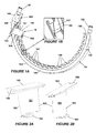
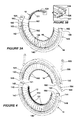
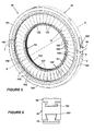
- Figures 1A , 3A , 4 and 5 show a high pressure steam turbine diaphragm 10 and which is constructed without welding or other fusion or adhesive metal joining techniques.
- the diaphragm 10 comprises a radially inner diaphragm ring 12, a radially outer diaphragm ring 14 and an annular array of static blade units 16 arranged between the inner and outer rings.
- the illustrated embodiment is a diaphragm with a radially compact type of construction, which has a much reduced radial thickness of its inner diaphragm ring 12 compared with the more robust type of construction traditionally used for large steam turbines.
- the inner diaphragm ring 12 of the illustrated embodiment is effectively part of all the inner platform port wall surfaces of the static blade units 16.
- the concept discussed herein is also applicable to diaphragms having inner rings which are radially thicker than the one illustrated and/or which do not form part of the inner platform surfaces.
- the outer ring 14 is constructed in two segments, an upper half 141 and a lower half 142, the two segments being united with each other at joint planes J.
- the number of segments in the outer ring 14 is at the option of the designer, consistent with requirements for cost-effective manufacture and assembly of the diaphragm 10.
- the joint planes J exhibit a scarf angle ⁇ , i.e., they are inclined away from alignment with the axial direction of the assembly (the axial direction being defined by reference to the major axis X-X of the diaphragm), as explained later, and the joint is bolted at 18 on diametrically opposite sides of the outer ring 14.
- bolt guide spacers 181, 182 are shown poised for insertion into bores 183 in planar joint faces 143, 144 of the lower half 142 of the outer diaphragm ring 14.
- Each bolt guide spacer 181, 182 essentially comprises a dowel having a bore which will allow the bolts of the bolted joint 18 to pass through it, and an external diameter which allows a push-fit into the bore 183.
- the bolt guide spacers 181, 182 are necessary because of the scarf angle of the joint faces.
- each planar joint face 143, 144 mates with a complementarily inclined planar joint face 145, 146 on the upper half 141 of the outer ring 14, and a projecting part of each bolt guide spacer 181, 182 fits inside a complementarily dimensioned bore 184 in the upper half 141 of the outer ring 14.
- the outer circumference of the upper half 141 of the outer ring 14 is specially recessed at 150 on opposite sides of the ring 14 to allow insertion of bolts 185 into the bores, which run tangentially of the ring. Only a distal end portion 186 of each bolt 185 is provided with a screw thread, which screws into a complementarily threaded portion of each bore 183 in the lower half 142 of outer ring 14.
- a blade unit 16 is shown poised for insertion into the lower half 142 of the outer ring 14.
- Each blade unit comprises an aerofoil portion 161, an inner platform portion 162 that engages the radially inner ring 12, and an outer platform portion 163 that engages the radially outer ring 14.
- the inner platform portion 162 is elongate in the circumferential direction of the inner ring 12
- the outer platform portion 163 is elongate in a direction which is generally transverse of the inner platform portion and compatible with the stagger angle of the blade aerofoils.
- the inner and outer platform portions 162, 163 are effectively cross-keyed relative to each other in the inner and outer rings 12 and 14 respectively, thus stabilising the blade units 16 within the diaphragm structure.
- an inner circumference of the radially outer ring is provided with blade unit retaining features 147 in the form of an array of angularly spaced-apart slots, each slot 147 being of complementary shape to the corresponding outer platform portion 163 of a static blade unit 16.
- the outer platform portions 163 are T-shaped in cross-section, as shown more clearly in Figure 2A .
- the slots 147 are also T-shaped, so that each T-shaped platform portion 163 fits inside an equivalent T-shaped slot 147 in the inner circumference of the radially outer ring 14.
- the slots 147 and the outer platform portions 163 of the static blade units 16 could be other than T-shaped in cross-section, e.g., dove-tail shaped or some other undercut or re-entrant shape that securely retains the blade units in an interlocking manner. It should also be appreciated that the slots 147 and the outer platform portions 163 of the static blade units 16 are oriented to match, or closely approximate, the stagger angle of the aerofoils 161. Hence, the planar joint faces 143 to 146 must be pitched at the same or a closely similar angle to the stagger angle in order to avoid the joint planes J ( Figure 5 ) cutting across any of the slots 147 in the outer ring 14.
- a stop feature 166 is provided at the inlet end of each outer platform portion 163.
- the stop feature 166 is in the form of a step that projects radially outwards of the rest of the platform portion 163 and fits into a matching complementary step 148 ( Figure 1B ) cut into the inlet end of the slots 147.
- Alternative stop features could be used; e.g., a step at the outlet end of the slot 147, the step projecting radially inwards of the radially outer part of the slot and fitting into a matching complementary step cut into the outlet end of the outer platform portion 163.
- the inner ring 12 comprises four segments, each of ninety degrees of arc, i.e., two segments 121 in the upper half 122 of the inner ring and two segments 121 in the lower half 123 of the inner ring.
- the inner ring 14 is made up of four segments to make assembly easier, it would also be possible for the inner ring to comprise only two segments, namely an upper half 122 and a lower half 123.
- the number of segments in the inner ring 12 is at the option of the designer, consistent with requirements for cost-effective manufacture and assembly of the diaphragm 10.
- FIG. 3A a segment 121 of the inner ring 12 is shown poised for attachment to the inner platform portions 162 of an assembled half ring of the static blade units 16.
- Each segment 121 has a blade unit retaining feature in the form of a circumferentially extending slot 124 in the outer circumference of the segment. Attachment of segment 121 to the inner platform portions 162 is achieved by sliding the slot 124 in segment 121 onto the inner platform portions 162 of the static blade units 16, the slot 124 being complementary in shape to the inner platform portions 162.
- the inner platform portions 162 are T-shaped in cross-section, as shown more clearly in Figures 2A and 2B , so that each T-shaped platform portion 162 fits inside the T-shaped slot 124 in the outer circumference of the inner ring 12, the slot 124 being shown more clearly in Figure 3B .
- slot 124 and the inner platform portions 162 of the static blade units 16 could be other than T-shaped in cross-section, e.g., dove-tail shaped or some other undercut or re-entrant shape that securely retains the blade units in an interlocking manner.
- each segment 121 of the radially inner ring 12 is configured as a labyrinth seal 127 for sealing directly against a rotor when the diaphragm has been assembled into a turbine, the seal being necessary to restrict leakage between relatively high and low pressure sides of the diaphragm,.
- the radially inner side of_a radially inner diaphragm ring to comprise a circumferentially extending recess configured to retain a separate seal therein, as shown diagrammatically in Figure 6 , which represents a fragmentary radial section through an inner ring 20 that is radially thicker than the inner ring 12, and therefore can carry segments of a separately formed labyrinth seal 22 in a dovetail-shaped slot 201 or other undercut or re-entrant shape machined in its radially inner side, the radially outer side of the inner ring 20 being engaged by the inner platform portions 162 of the static blade units 16, as previously described.
- seals such as brush or leaf seals
- the labyrinth seal may be substituted for the labyrinth seal, and/or provision may be made for the seal to be spring-mounted in the slot 201, so that it can automatically adjust to variations in the clearance between the inner ring 20 and the rotor surface (not shown) against which the seal acts.
- the blade units are machined as single components complete with aerofoils and inner and outer platforms, so that when the platforms are welded onto their respective inner and outer rings, the inner platforms combine to create an inner port wall and the outer platforms combine to create an outer port wall.
- the present concept for platform construction is distinct from the traditional type, in that the inner and outer blade platforms are reduced to elongate attachment features 162, 163 that are retained in complementary-shaped blade-retaining features 124, 147 provided in the inner and outer diaphragm rings 12, 14.
- the radially outer platform portions 163 of the blade units 16 are elongate in directions compatible with the stagger angle of the blade aerofoils 161, whereas the radially inner platform portions 162 of the blade units 16 are elongate in the circumferential direction of the inner ring 12.
- the radially outer port wall of the diaphragm comprises the radially outer elongate platform portions 163 of the blade units 16, alternating in the circumferential direction with exposed portions 149 of the inner circumference of the outer diaphragm ring 14.
- the radially inner port wall of the diaphragm 10 comprises the radially inner elongate platform portions 162 of the blade units 16, flanked on their axially opposed (inlet and outlet) sides by exposed portions 126 (see also Figure 3B ) of the outer circumference of the inner diaphragm ring 12.
- exposed portions 126 see also Figure 3B
- the ends of the elongate platform portions 162 butt up to each other when inserted into the inner ring 12, so that the platform portions 162 extend continuously around the inner port wall in the circumferential direction, as do the exposed portions 126 of the inner diaphragm ring 12.
- the inner and outer port walls of the diaphragm are sufficiently smooth to avoid excessive aerodynamic drag penalties, and to this end the platform portions of the blade units and the blade retaining features of the inner and outer rings should be accurately manufactured and closely matched to each other with regard to their dimensions and surface finishes.
Landscapes
- Engineering & Computer Science (AREA)
- Mechanical Engineering (AREA)
- General Engineering & Computer Science (AREA)
- Turbine Rotor Nozzle Sealing (AREA)
Priority Applications (4)
| Application Number | Priority Date | Filing Date | Title |
|---|---|---|---|
| EP12165618.5A EP2657454B1 (fr) | 2012-04-26 | 2012-04-26 | Structure de diaphragme de turbine |
| US13/863,685 US9840928B2 (en) | 2012-04-26 | 2013-04-16 | Turbine diaphragm construction |
| JP2013092869A JP5653476B2 (ja) | 2012-04-26 | 2013-04-25 | タービンダイアフラム構成 |
| CN201310149528.0A CN103375180B (zh) | 2012-04-26 | 2013-04-26 | 涡轮隔板构造 |
Applications Claiming Priority (1)
| Application Number | Priority Date | Filing Date | Title |
|---|---|---|---|
| EP12165618.5A EP2657454B1 (fr) | 2012-04-26 | 2012-04-26 | Structure de diaphragme de turbine |
Publications (2)
| Publication Number | Publication Date |
|---|---|
| EP2657454A1 true EP2657454A1 (fr) | 2013-10-30 |
| EP2657454B1 EP2657454B1 (fr) | 2014-05-14 |
Family
ID=46044478
Family Applications (1)
| Application Number | Title | Priority Date | Filing Date |
|---|---|---|---|
| EP12165618.5A Active EP2657454B1 (fr) | 2012-04-26 | 2012-04-26 | Structure de diaphragme de turbine |
Country Status (4)
| Country | Link |
|---|---|
| US (1) | US9840928B2 (fr) |
| EP (1) | EP2657454B1 (fr) |
| JP (1) | JP5653476B2 (fr) |
| CN (1) | CN103375180B (fr) |
Cited By (3)
| Publication number | Priority date | Publication date | Assignee | Title |
|---|---|---|---|---|
| CN104942551A (zh) * | 2015-07-15 | 2015-09-30 | 上海电气电站设备有限公司 | 斜置式静叶环及其制造方法 |
| WO2021139939A1 (fr) * | 2020-01-07 | 2021-07-15 | Siemens Aktiengesellschaft | Anneau d'aube directrice doté d'éléments d'usure |
| EP3835552A4 (fr) * | 2018-09-28 | 2021-08-25 | Mitsubishi Heavy Industries Compressor Corporation | Stator de turbine, turbine à vapeur et plaque de séparation |
Families Citing this family (19)
| Publication number | Priority date | Publication date | Assignee | Title |
|---|---|---|---|---|
| FR2972380A1 (fr) * | 2011-03-11 | 2012-09-14 | Alstom Technology Ltd | Procede de fabrication d'un diaphragme de turbine a vapeur |
| DE102013210427A1 (de) * | 2013-06-05 | 2014-12-11 | Rolls-Royce Deutschland Ltd & Co Kg | Deckbandanordnung für eine Strömungsmaschine |
| USD777212S1 (en) * | 2015-06-20 | 2017-01-24 | General Electric Company | Nozzle ring |
| CN106089335B (zh) * | 2016-07-22 | 2017-09-19 | 哈尔滨汽轮机厂有限责任公司 | 汽轮机叶片试装配用承载装置及其装配方法 |
| PL3284919T3 (pl) * | 2016-08-16 | 2024-12-09 | General Electric Technology Gmbh | Turbina o przepływie osiowym mająca kryzę podzieloną na dwie połowy w płaszczyźnie połączenia |
| CN106121856A (zh) * | 2016-08-25 | 2016-11-16 | 张家港市中程进出口贸易有限公司 | 内燃机二级隔板 |
| CN106121855A (zh) * | 2016-08-25 | 2016-11-16 | 张家港市中程进出口贸易有限公司 | 一种内燃机二级隔板 |
| CN106194491A (zh) * | 2016-08-25 | 2016-12-07 | 张家港市中程进出口贸易有限公司 | 一种内燃机隔板 |
| CN107676178A (zh) * | 2017-11-10 | 2018-02-09 | 张家港市三林金泰新能源有限公司 | 新型能源内燃机的隔板 |
| KR101950922B1 (ko) * | 2018-09-06 | 2019-02-21 | 터보파워텍(주) | 가스터빈용 베인조립체 |
| IT201900014724A1 (it) | 2019-08-13 | 2021-02-13 | Ge Avio Srl | Elementi di trattenimento delle pale per turbomacchine. |
| IT201900014739A1 (it) | 2019-08-13 | 2021-02-13 | Ge Avio Srl | Elementi di trattenimento delle pale per turbomacchine. |
| IT201900014736A1 (it) | 2019-08-13 | 2021-02-13 | Ge Avio Srl | Elementi di tenuta integrali per pale trattenute in un rotore a tamburo esterno anulare girevole in una turbomacchina. |
| JP7284737B2 (ja) * | 2020-08-06 | 2023-05-31 | 三菱重工業株式会社 | ガスタービン静翼 |
| CN112177688A (zh) * | 2020-09-28 | 2021-01-05 | 宁国市华成金研科技有限公司 | 一种发动机精铸导向器及其加工方法 |
| US11549388B2 (en) | 2021-01-18 | 2023-01-10 | Raytheon Technologies Corporation | Inner shroud assembly for gas turbine engine variable vane system |
| CN113202569A (zh) * | 2021-06-16 | 2021-08-03 | 中国航发沈阳发动机研究所 | 一种发动机静子结构 |
| CN113202568A (zh) * | 2021-06-16 | 2021-08-03 | 中国航发沈阳发动机研究所 | 一种发动机静子结构及其装配方法 |
| CN113847105B (zh) * | 2021-10-26 | 2024-06-11 | 中国航发沈阳发动机研究所 | 一种发动机奇数可调静子叶片静子部件装配结构及其方法 |
Citations (3)
| Publication number | Priority date | Publication date | Assignee | Title |
|---|---|---|---|---|
| EP0945597A1 (fr) * | 1998-03-23 | 1999-09-29 | Asea Brown Boveri AG | Montage des aubes statoriques dans une installation de turbine à gas |
| EP1408198A1 (fr) * | 2001-07-19 | 2004-04-14 | Toshiba Carrier Corporation | Membrane de buse de type a assembler et procede d'assemblage |
| US20070086892A1 (en) * | 2005-10-18 | 2007-04-19 | Tomko Andrew J | Machine tooled diaphragm partitions and nozzles |
Family Cites Families (14)
| Publication number | Priority date | Publication date | Assignee | Title |
|---|---|---|---|---|
| JPS5171901A (fr) | 1974-12-18 | 1976-06-22 | Hitachi Ltd | |
| US4455730A (en) | 1982-08-30 | 1984-06-26 | Westinghouse Electric Corp. | Turbine blade extractor |
| FR2675536B1 (fr) | 1991-04-19 | 1994-12-09 | Alsthom Gec | Turbine a action a rotor tambour et perfectionnement a ces turbines. |
| JP2754992B2 (ja) * | 1991-12-20 | 1998-05-20 | 日産自動車株式会社 | タービンロータの分割および一体成形方法 |
| JP4437515B2 (ja) | 2000-08-01 | 2010-03-24 | 株式会社Ihi | タービンノズルの製造方法 |
| JP2005146896A (ja) | 2003-11-11 | 2005-06-09 | Toshiba Corp | 蒸気タービンのノズルダイアフラムおよび蒸気タービンプラント |
| JP4326315B2 (ja) | 2003-12-08 | 2009-09-02 | 三菱重工業株式会社 | 翼環構造 |
| JP2006125282A (ja) | 2004-10-28 | 2006-05-18 | Mitsubishi Heavy Ind Ltd | タービンの翼列構造、及び、タービン翼列構造の冷却方法 |
| GB0505978D0 (en) * | 2005-03-24 | 2005-04-27 | Alstom Technology Ltd | Interlocking turbine blades |
| US7217099B2 (en) | 2005-05-24 | 2007-05-15 | General Electric Company | Coated forward stub shaft dovetail slot |
| JP2008144687A (ja) | 2006-12-12 | 2008-06-26 | Mitsubishi Heavy Ind Ltd | タービン静翼構造 |
| CN201424965Y (zh) | 2009-04-22 | 2010-03-17 | 宰汉林 | 一种背压式汽轮机喷嘴 |
| JP2010270717A (ja) | 2009-05-22 | 2010-12-02 | Hitachi Ltd | タービン静翼の植え込み方法、及びタービンノズル |
| US20150211372A1 (en) * | 2014-01-30 | 2015-07-30 | Solar Turbines Incorporated | Hot isostatic pressing to heal weld cracks |
-
2012
- 2012-04-26 EP EP12165618.5A patent/EP2657454B1/fr active Active
-
2013
- 2013-04-16 US US13/863,685 patent/US9840928B2/en active Active
- 2013-04-25 JP JP2013092869A patent/JP5653476B2/ja active Active
- 2013-04-26 CN CN201310149528.0A patent/CN103375180B/zh active Active
Patent Citations (3)
| Publication number | Priority date | Publication date | Assignee | Title |
|---|---|---|---|---|
| EP0945597A1 (fr) * | 1998-03-23 | 1999-09-29 | Asea Brown Boveri AG | Montage des aubes statoriques dans une installation de turbine à gas |
| EP1408198A1 (fr) * | 2001-07-19 | 2004-04-14 | Toshiba Carrier Corporation | Membrane de buse de type a assembler et procede d'assemblage |
| US20070086892A1 (en) * | 2005-10-18 | 2007-04-19 | Tomko Andrew J | Machine tooled diaphragm partitions and nozzles |
Cited By (8)
| Publication number | Priority date | Publication date | Assignee | Title |
|---|---|---|---|---|
| CN104942551A (zh) * | 2015-07-15 | 2015-09-30 | 上海电气电站设备有限公司 | 斜置式静叶环及其制造方法 |
| CN104942551B (zh) * | 2015-07-15 | 2017-06-20 | 上海电气电站设备有限公司 | 斜置式静叶环及其制造方法 |
| EP3835552A4 (fr) * | 2018-09-28 | 2021-08-25 | Mitsubishi Heavy Industries Compressor Corporation | Stator de turbine, turbine à vapeur et plaque de séparation |
| US11655733B2 (en) | 2018-09-28 | 2023-05-23 | Mitsubishi Heavy Industries Compressor Corporation | Turbine stator, steam turbine, and partition plate |
| WO2021139939A1 (fr) * | 2020-01-07 | 2021-07-15 | Siemens Aktiengesellschaft | Anneau d'aube directrice doté d'éléments d'usure |
| CN114945733A (zh) * | 2020-01-07 | 2022-08-26 | 西门子能源全球有限两合公司 | 具有磨损元件的导向叶片环 |
| CN114945733B (zh) * | 2020-01-07 | 2023-10-20 | 西门子能源全球有限两合公司 | 具有磨损元件的导向叶片环 |
| US11965432B2 (en) | 2020-01-07 | 2024-04-23 | Siemens Energy Global GmbH & Co. KG | Guide vane ring with wear elements |
Also Published As
| Publication number | Publication date |
|---|---|
| JP2013227980A (ja) | 2013-11-07 |
| EP2657454B1 (fr) | 2014-05-14 |
| US9840928B2 (en) | 2017-12-12 |
| JP5653476B2 (ja) | 2015-01-14 |
| CN103375180A (zh) | 2013-10-30 |
| US20130287563A1 (en) | 2013-10-31 |
| CN103375180B (zh) | 2016-01-20 |
Similar Documents
| Publication | Publication Date | Title |
|---|---|---|
| US9840928B2 (en) | Turbine diaphragm construction | |
| US9453425B2 (en) | Turbine diaphragm construction | |
| US9127559B2 (en) | Diaphragm for turbomachines and method of manufacture | |
| US5302086A (en) | Apparatus for retaining rotor blades | |
| EP3026212A1 (fr) | Dégagement de face de grille monobloc | |
| EP3123002B1 (fr) | Système de support d'aube de stator à l'intérieur d'un moteur à turbine à gaz | |
| US20090148279A1 (en) | Gas turbine belly band seal anti-rotation structure | |
| EP1953347A2 (fr) | Appareil de stator sans Stablug et procédé de montage | |
| US9739159B2 (en) | Method and system for relieving turbine rotor blade dovetail stress | |
| US8562292B2 (en) | Steam turbine singlet interface for margin stage nozzles with pinned or bolted inner ring | |
| EP3112598B1 (fr) | Segment de tuyère de turbine à vapeur pour application à arc partiel, ensemble associé et turbine à vapeur | |
| US9650918B2 (en) | Austenitic segment for steam turbine nozzle assembly, and related assembly | |
| EP2564979B1 (fr) | Procédé pour réparer un anneau à bride circonférentiel d'une turbine à gaz et assemblage d'une douille et d'un anneau à bride circonférentiel d'une turbine à gaz | |
| RU2793871C1 (ru) | Наборная диафрагма паровой турбины | |
| US9334746B2 (en) | Turbomachine flow divider and related turbomachine |
Legal Events
| Date | Code | Title | Description |
|---|---|---|---|
| PUAI | Public reference made under article 153(3) epc to a published international application that has entered the european phase |
Free format text: ORIGINAL CODE: 0009012 |
|
| AK | Designated contracting states |
Kind code of ref document: A1 Designated state(s): AL AT BE BG CH CY CZ DE DK EE ES FI FR GB GR HR HU IE IS IT LI LT LU LV MC MK MT NL NO PL PT RO RS SE SI SK SM TR |
|
| AX | Request for extension of the european patent |
Extension state: BA ME |
|
| 17P | Request for examination filed |
Effective date: 20131024 |
|
| RBV | Designated contracting states (corrected) |
Designated state(s): AL AT BE BG CH CY CZ DE DK EE ES FI FR GB GR HR HU IE IS IT LI LT LU LV MC MK MT NL NO PL PT RO RS SE SI SK SM TR |
|
| GRAP | Despatch of communication of intention to grant a patent |
Free format text: ORIGINAL CODE: EPIDOSNIGR1 |
|
| INTG | Intention to grant announced |
Effective date: 20140227 |
|
| GRAS | Grant fee paid |
Free format text: ORIGINAL CODE: EPIDOSNIGR3 |
|
| GRAA | (expected) grant |
Free format text: ORIGINAL CODE: 0009210 |
|
| AK | Designated contracting states |
Kind code of ref document: B1 Designated state(s): AL AT BE BG CH CY CZ DE DK EE ES FI FR GB GR HR HU IE IS IT LI LT LU LV MC MK MT NL NO PL PT RO RS SE SI SK SM TR |
|
| REG | Reference to a national code |
Ref country code: GB Ref legal event code: FG4D |
|
| REG | Reference to a national code |
Ref country code: AT Ref legal event code: REF Ref document number: 668457 Country of ref document: AT Kind code of ref document: T Effective date: 20140615 |
|
| REG | Reference to a national code |
Ref country code: IE Ref legal event code: FG4D |
|
| REG | Reference to a national code |
Ref country code: DE Ref legal event code: R096 Ref document number: 602012001689 Country of ref document: DE Effective date: 20140703 |
|
| REG | Reference to a national code |
Ref country code: NL Ref legal event code: VDEP Effective date: 20140514 Ref country code: AT Ref legal event code: MK05 Ref document number: 668457 Country of ref document: AT Kind code of ref document: T Effective date: 20140514 |
|
| REG | Reference to a national code |
Ref country code: LT Ref legal event code: MG4D |
|
| PG25 | Lapsed in a contracting state [announced via postgrant information from national office to epo] |
Ref country code: NO Free format text: LAPSE BECAUSE OF FAILURE TO SUBMIT A TRANSLATION OF THE DESCRIPTION OR TO PAY THE FEE WITHIN THE PRESCRIBED TIME-LIMIT Effective date: 20140814 Ref country code: LT Free format text: LAPSE BECAUSE OF FAILURE TO SUBMIT A TRANSLATION OF THE DESCRIPTION OR TO PAY THE FEE WITHIN THE PRESCRIBED TIME-LIMIT Effective date: 20140514 Ref country code: GR Free format text: LAPSE BECAUSE OF FAILURE TO SUBMIT A TRANSLATION OF THE DESCRIPTION OR TO PAY THE FEE WITHIN THE PRESCRIBED TIME-LIMIT Effective date: 20140815 Ref country code: IS Free format text: LAPSE BECAUSE OF FAILURE TO SUBMIT A TRANSLATION OF THE DESCRIPTION OR TO PAY THE FEE WITHIN THE PRESCRIBED TIME-LIMIT Effective date: 20140914 Ref country code: FI Free format text: LAPSE BECAUSE OF FAILURE TO SUBMIT A TRANSLATION OF THE DESCRIPTION OR TO PAY THE FEE WITHIN THE PRESCRIBED TIME-LIMIT Effective date: 20140514 Ref country code: CY Free format text: LAPSE BECAUSE OF FAILURE TO SUBMIT A TRANSLATION OF THE DESCRIPTION OR TO PAY THE FEE WITHIN THE PRESCRIBED TIME-LIMIT Effective date: 20140514 |
|
| PG25 | Lapsed in a contracting state [announced via postgrant information from national office to epo] |
Ref country code: ES Free format text: LAPSE BECAUSE OF FAILURE TO SUBMIT A TRANSLATION OF THE DESCRIPTION OR TO PAY THE FEE WITHIN THE PRESCRIBED TIME-LIMIT Effective date: 20140514 Ref country code: PL Free format text: LAPSE BECAUSE OF FAILURE TO SUBMIT A TRANSLATION OF THE DESCRIPTION OR TO PAY THE FEE WITHIN THE PRESCRIBED TIME-LIMIT Effective date: 20140514 Ref country code: RS Free format text: LAPSE BECAUSE OF FAILURE TO SUBMIT A TRANSLATION OF THE DESCRIPTION OR TO PAY THE FEE WITHIN THE PRESCRIBED TIME-LIMIT Effective date: 20140514 Ref country code: HR Free format text: LAPSE BECAUSE OF FAILURE TO SUBMIT A TRANSLATION OF THE DESCRIPTION OR TO PAY THE FEE WITHIN THE PRESCRIBED TIME-LIMIT Effective date: 20140514 Ref country code: LV Free format text: LAPSE BECAUSE OF FAILURE TO SUBMIT A TRANSLATION OF THE DESCRIPTION OR TO PAY THE FEE WITHIN THE PRESCRIBED TIME-LIMIT Effective date: 20140514 Ref country code: SE Free format text: LAPSE BECAUSE OF FAILURE TO SUBMIT A TRANSLATION OF THE DESCRIPTION OR TO PAY THE FEE WITHIN THE PRESCRIBED TIME-LIMIT Effective date: 20140514 Ref country code: AT Free format text: LAPSE BECAUSE OF FAILURE TO SUBMIT A TRANSLATION OF THE DESCRIPTION OR TO PAY THE FEE WITHIN THE PRESCRIBED TIME-LIMIT Effective date: 20140514 |
|
| PG25 | Lapsed in a contracting state [announced via postgrant information from national office to epo] |
Ref country code: PT Free format text: LAPSE BECAUSE OF FAILURE TO SUBMIT A TRANSLATION OF THE DESCRIPTION OR TO PAY THE FEE WITHIN THE PRESCRIBED TIME-LIMIT Effective date: 20140915 |
|
| PG25 | Lapsed in a contracting state [announced via postgrant information from national office to epo] |
Ref country code: EE Free format text: LAPSE BECAUSE OF FAILURE TO SUBMIT A TRANSLATION OF THE DESCRIPTION OR TO PAY THE FEE WITHIN THE PRESCRIBED TIME-LIMIT Effective date: 20140514 Ref country code: BE Free format text: LAPSE BECAUSE OF FAILURE TO SUBMIT A TRANSLATION OF THE DESCRIPTION OR TO PAY THE FEE WITHIN THE PRESCRIBED TIME-LIMIT Effective date: 20140514 Ref country code: CZ Free format text: LAPSE BECAUSE OF FAILURE TO SUBMIT A TRANSLATION OF THE DESCRIPTION OR TO PAY THE FEE WITHIN THE PRESCRIBED TIME-LIMIT Effective date: 20140514 Ref country code: SK Free format text: LAPSE BECAUSE OF FAILURE TO SUBMIT A TRANSLATION OF THE DESCRIPTION OR TO PAY THE FEE WITHIN THE PRESCRIBED TIME-LIMIT Effective date: 20140514 Ref country code: RO Free format text: LAPSE BECAUSE OF FAILURE TO SUBMIT A TRANSLATION OF THE DESCRIPTION OR TO PAY THE FEE WITHIN THE PRESCRIBED TIME-LIMIT Effective date: 20140514 Ref country code: DK Free format text: LAPSE BECAUSE OF FAILURE TO SUBMIT A TRANSLATION OF THE DESCRIPTION OR TO PAY THE FEE WITHIN THE PRESCRIBED TIME-LIMIT Effective date: 20140514 |
|
| REG | Reference to a national code |
Ref country code: DE Ref legal event code: R097 Ref document number: 602012001689 Country of ref document: DE |
|
| PG25 | Lapsed in a contracting state [announced via postgrant information from national office to epo] |
Ref country code: NL Free format text: LAPSE BECAUSE OF FAILURE TO SUBMIT A TRANSLATION OF THE DESCRIPTION OR TO PAY THE FEE WITHIN THE PRESCRIBED TIME-LIMIT Effective date: 20140514 |
|
| PLBE | No opposition filed within time limit |
Free format text: ORIGINAL CODE: 0009261 |
|
| STAA | Information on the status of an ep patent application or granted ep patent |
Free format text: STATUS: NO OPPOSITION FILED WITHIN TIME LIMIT |
|
| 26N | No opposition filed |
Effective date: 20150217 |
|
| PG25 | Lapsed in a contracting state [announced via postgrant information from national office to epo] |
Ref country code: IT Free format text: LAPSE BECAUSE OF FAILURE TO SUBMIT A TRANSLATION OF THE DESCRIPTION OR TO PAY THE FEE WITHIN THE PRESCRIBED TIME-LIMIT Effective date: 20140514 |
|
| REG | Reference to a national code |
Ref country code: DE Ref legal event code: R097 Ref document number: 602012001689 Country of ref document: DE Effective date: 20150217 |
|
| PG25 | Lapsed in a contracting state [announced via postgrant information from national office to epo] |
Ref country code: SI Free format text: LAPSE BECAUSE OF FAILURE TO SUBMIT A TRANSLATION OF THE DESCRIPTION OR TO PAY THE FEE WITHIN THE PRESCRIBED TIME-LIMIT Effective date: 20140514 |
|
| PG25 | Lapsed in a contracting state [announced via postgrant information from national office to epo] |
Ref country code: LU Free format text: LAPSE BECAUSE OF FAILURE TO SUBMIT A TRANSLATION OF THE DESCRIPTION OR TO PAY THE FEE WITHIN THE PRESCRIBED TIME-LIMIT Effective date: 20150426 Ref country code: MC Free format text: LAPSE BECAUSE OF FAILURE TO SUBMIT A TRANSLATION OF THE DESCRIPTION OR TO PAY THE FEE WITHIN THE PRESCRIBED TIME-LIMIT Effective date: 20140514 |
|
| REG | Reference to a national code |
Ref country code: IE Ref legal event code: MM4A |
|
| REG | Reference to a national code |
Ref country code: FR Ref legal event code: ST Effective date: 20151231 |
|
| PG25 | Lapsed in a contracting state [announced via postgrant information from national office to epo] |
Ref country code: FR Free format text: LAPSE BECAUSE OF NON-PAYMENT OF DUE FEES Effective date: 20150430 |
|
| PG25 | Lapsed in a contracting state [announced via postgrant information from national office to epo] |
Ref country code: IE Free format text: LAPSE BECAUSE OF NON-PAYMENT OF DUE FEES Effective date: 20150426 |
|
| REG | Reference to a national code |
Ref country code: CH Ref legal event code: PFA Owner name: GENERAL ELECTRIC TECHNOLOGY GMBH, CH Free format text: FORMER OWNER: ALSTOM TECHNOLOGY LTD, CH |
|
| REG | Reference to a national code |
Ref country code: DE Ref legal event code: R082 Ref document number: 602012001689 Country of ref document: DE Representative=s name: RUEGER | ABEL PATENT- UND RECHTSANWAELTE, DE Ref country code: DE Ref legal event code: R082 Ref document number: 602012001689 Country of ref document: DE Representative=s name: RUEGER ABEL PATENTANWAELTE PARTGMBB, DE Ref country code: DE Ref legal event code: R082 Ref document number: 602012001689 Country of ref document: DE Representative=s name: RUEGER, BARTHELT & ABEL, DE Ref country code: DE Ref legal event code: R081 Ref document number: 602012001689 Country of ref document: DE Owner name: GENERAL ELECTRIC TECHNOLOGY GMBH, CH Free format text: FORMER OWNER: ALSTOM TECHNOLOGY LTD., BADEN, CH Ref country code: DE Ref legal event code: R082 Ref document number: 602012001689 Country of ref document: DE Representative=s name: RUEGER ABEL PATENT- UND RECHTSANWAELTE, DE |
|
| GBPC | Gb: european patent ceased through non-payment of renewal fee |
Effective date: 20160426 |
|
| PG25 | Lapsed in a contracting state [announced via postgrant information from national office to epo] |
Ref country code: MT Free format text: LAPSE BECAUSE OF FAILURE TO SUBMIT A TRANSLATION OF THE DESCRIPTION OR TO PAY THE FEE WITHIN THE PRESCRIBED TIME-LIMIT Effective date: 20140514 |
|
| PG25 | Lapsed in a contracting state [announced via postgrant information from national office to epo] |
Ref country code: GB Free format text: LAPSE BECAUSE OF NON-PAYMENT OF DUE FEES Effective date: 20160426 |
|
| PG25 | Lapsed in a contracting state [announced via postgrant information from national office to epo] |
Ref country code: BG Free format text: LAPSE BECAUSE OF FAILURE TO SUBMIT A TRANSLATION OF THE DESCRIPTION OR TO PAY THE FEE WITHIN THE PRESCRIBED TIME-LIMIT Effective date: 20140514 Ref country code: SM Free format text: LAPSE BECAUSE OF FAILURE TO SUBMIT A TRANSLATION OF THE DESCRIPTION OR TO PAY THE FEE WITHIN THE PRESCRIBED TIME-LIMIT Effective date: 20140514 Ref country code: HU Free format text: LAPSE BECAUSE OF FAILURE TO SUBMIT A TRANSLATION OF THE DESCRIPTION OR TO PAY THE FEE WITHIN THE PRESCRIBED TIME-LIMIT; INVALID AB INITIO Effective date: 20120426 |
|
| PGFP | Annual fee paid to national office [announced via postgrant information from national office to epo] |
Ref country code: CH Payment date: 20170427 Year of fee payment: 6 |
|
| PG25 | Lapsed in a contracting state [announced via postgrant information from national office to epo] |
Ref country code: TR Free format text: LAPSE BECAUSE OF FAILURE TO SUBMIT A TRANSLATION OF THE DESCRIPTION OR TO PAY THE FEE WITHIN THE PRESCRIBED TIME-LIMIT Effective date: 20140514 |
|
| PG25 | Lapsed in a contracting state [announced via postgrant information from national office to epo] |
Ref country code: MK Free format text: LAPSE BECAUSE OF FAILURE TO SUBMIT A TRANSLATION OF THE DESCRIPTION OR TO PAY THE FEE WITHIN THE PRESCRIBED TIME-LIMIT Effective date: 20140514 |
|
| PG25 | Lapsed in a contracting state [announced via postgrant information from national office to epo] |
Ref country code: AL Free format text: LAPSE BECAUSE OF FAILURE TO SUBMIT A TRANSLATION OF THE DESCRIPTION OR TO PAY THE FEE WITHIN THE PRESCRIBED TIME-LIMIT Effective date: 20140514 |
|
| REG | Reference to a national code |
Ref country code: CH Ref legal event code: PL |
|
| PG25 | Lapsed in a contracting state [announced via postgrant information from national office to epo] |
Ref country code: CH Free format text: LAPSE BECAUSE OF NON-PAYMENT OF DUE FEES Effective date: 20180430 Ref country code: LI Free format text: LAPSE BECAUSE OF NON-PAYMENT OF DUE FEES Effective date: 20180430 |
|
| P01 | Opt-out of the competence of the unified patent court (upc) registered |
Effective date: 20230523 |
|
| REG | Reference to a national code |
Ref country code: DE Ref legal event code: R081 Ref document number: 602012001689 Country of ref document: DE Owner name: ARABELLE SOLUTIONS FRANCE, FR Free format text: FORMER OWNER: GENERAL ELECTRIC TECHNOLOGY GMBH, BADEN, CH Ref country code: DE Ref legal event code: R081 Ref document number: 602012001689 Country of ref document: DE Owner name: ARABELLE TECHNOLOGIES, FR Free format text: FORMER OWNER: GENERAL ELECTRIC TECHNOLOGY GMBH, BADEN, CH |
|
| REG | Reference to a national code |
Ref country code: DE Ref legal event code: R081 Ref document number: 602012001689 Country of ref document: DE Owner name: ARABELLE SOLUTIONS FRANCE, FR Free format text: FORMER OWNER: ARABELLE TECHNOLOGIES, BOULOGNE-BILLANCOURT, FR |
|
| PGFP | Annual fee paid to national office [announced via postgrant information from national office to epo] |
Ref country code: DE Payment date: 20250319 Year of fee payment: 14 |