EP2657543B1 - High retention fastener - Google Patents
High retention fastener Download PDFInfo
- Publication number
- EP2657543B1 EP2657543B1 EP13165269.5A EP13165269A EP2657543B1 EP 2657543 B1 EP2657543 B1 EP 2657543B1 EP 13165269 A EP13165269 A EP 13165269A EP 2657543 B1 EP2657543 B1 EP 2657543B1
- Authority
- EP
- European Patent Office
- Prior art keywords
- fastener
- panel
- retention
- wing
- tooth
- Prior art date
- Legal status (The legal status is an assumption and is not a legal conclusion. Google has not performed a legal analysis and makes no representation as to the accuracy of the status listed.)
- Not-in-force
Links
- 230000014759 maintenance of location Effects 0.000 title claims description 67
- 238000005452 bending Methods 0.000 claims description 9
- 238000009434 installation Methods 0.000 claims description 9
- 239000000463 material Substances 0.000 description 8
- 238000000034 method Methods 0.000 description 4
- HCHKCACWOHOZIP-UHFFFAOYSA-N Zinc Chemical compound [Zn] HCHKCACWOHOZIP-UHFFFAOYSA-N 0.000 description 3
- 239000011248 coating agent Substances 0.000 description 3
- 238000000576 coating method Methods 0.000 description 3
- 230000007423 decrease Effects 0.000 description 3
- 238000003780 insertion Methods 0.000 description 3
- 230000037431 insertion Effects 0.000 description 3
- 239000002184 metal Substances 0.000 description 3
- 229910052751 metal Inorganic materials 0.000 description 3
- 229910052725 zinc Inorganic materials 0.000 description 3
- 239000011701 zinc Substances 0.000 description 3
- 238000005260 corrosion Methods 0.000 description 2
- 230000007797 corrosion Effects 0.000 description 2
- 238000012986 modification Methods 0.000 description 2
- 230000004048 modification Effects 0.000 description 2
- 238000000465 moulding Methods 0.000 description 2
- 229910000639 Spring steel Inorganic materials 0.000 description 1
- 238000013459 approach Methods 0.000 description 1
- 230000003247 decreasing effect Effects 0.000 description 1
- 238000005516 engineering process Methods 0.000 description 1
- 230000009972 noncorrosive effect Effects 0.000 description 1
- 238000004080 punching Methods 0.000 description 1
- 230000000717 retained effect Effects 0.000 description 1
Images


Classifications
-
- F—MECHANICAL ENGINEERING; LIGHTING; HEATING; WEAPONS; BLASTING
- F16—ENGINEERING ELEMENTS AND UNITS; GENERAL MEASURES FOR PRODUCING AND MAINTAINING EFFECTIVE FUNCTIONING OF MACHINES OR INSTALLATIONS; THERMAL INSULATION IN GENERAL
- F16B—DEVICES FOR FASTENING OR SECURING CONSTRUCTIONAL ELEMENTS OR MACHINE PARTS TOGETHER, e.g. NAILS, BOLTS, CIRCLIPS, CLAMPS, CLIPS OR WEDGES; JOINTS OR JOINTING
- F16B5/00—Joining sheets or plates, e.g. panels, to one another or to strips or bars parallel to them
- F16B5/06—Joining sheets or plates, e.g. panels, to one another or to strips or bars parallel to them by means of clamps or clips
- F16B5/0607—Joining sheets or plates, e.g. panels, to one another or to strips or bars parallel to them by means of clamps or clips joining sheets or plates to each other
- F16B5/0621—Joining sheets or plates, e.g. panels, to one another or to strips or bars parallel to them by means of clamps or clips joining sheets or plates to each other in parallel relationship
- F16B5/0642—Joining sheets or plates, e.g. panels, to one another or to strips or bars parallel to them by means of clamps or clips joining sheets or plates to each other in parallel relationship the plates being arranged one on top of the other and in full close contact with each other
-
- B—PERFORMING OPERATIONS; TRANSPORTING
- B60—VEHICLES IN GENERAL
- B60R—VEHICLES, VEHICLE FITTINGS, OR VEHICLE PARTS, NOT OTHERWISE PROVIDED FOR
- B60R13/00—Elements for body-finishing, identifying, or decorating; Arrangements or adaptations for advertising purposes
- B60R13/02—Internal Trim mouldings ; Internal Ledges; Wall liners for passenger compartments; Roof liners
- B60R13/0206—Arrangements of fasteners and clips specially adapted for attaching inner vehicle liners or mouldings
-
- F—MECHANICAL ENGINEERING; LIGHTING; HEATING; WEAPONS; BLASTING
- F16—ENGINEERING ELEMENTS AND UNITS; GENERAL MEASURES FOR PRODUCING AND MAINTAINING EFFECTIVE FUNCTIONING OF MACHINES OR INSTALLATIONS; THERMAL INSULATION IN GENERAL
- F16B—DEVICES FOR FASTENING OR SECURING CONSTRUCTIONAL ELEMENTS OR MACHINE PARTS TOGETHER, e.g. NAILS, BOLTS, CIRCLIPS, CLAMPS, CLIPS OR WEDGES; JOINTS OR JOINTING
- F16B37/00—Nuts or like thread-engaging members
- F16B37/04—Devices for fastening nuts to surfaces, e.g. sheets, plates
- F16B37/041—Releasable devices
- F16B37/043—Releasable devices with snap action
-
- Y—GENERAL TAGGING OF NEW TECHNOLOGICAL DEVELOPMENTS; GENERAL TAGGING OF CROSS-SECTIONAL TECHNOLOGIES SPANNING OVER SEVERAL SECTIONS OF THE IPC; TECHNICAL SUBJECTS COVERED BY FORMER USPC CROSS-REFERENCE ART COLLECTIONS [XRACs] AND DIGESTS
- Y10—TECHNICAL SUBJECTS COVERED BY FORMER USPC
- Y10T—TECHNICAL SUBJECTS COVERED BY FORMER US CLASSIFICATION
- Y10T24/00—Buckles, buttons, clasps, etc.
- Y10T24/14—Bale and package ties, hose clamps
- Y10T24/1412—Bale and package ties, hose clamps with tighteners
- Y10T24/1441—Tangential screw
- Y10T24/1443—Adjustable girth
- Y10T24/1445—Step adjustment
- Y10T24/1447—Plural separable parts
-
- Y—GENERAL TAGGING OF NEW TECHNOLOGICAL DEVELOPMENTS; GENERAL TAGGING OF CROSS-SECTIONAL TECHNOLOGIES SPANNING OVER SEVERAL SECTIONS OF THE IPC; TECHNICAL SUBJECTS COVERED BY FORMER USPC CROSS-REFERENCE ART COLLECTIONS [XRACs] AND DIGESTS
- Y10—TECHNICAL SUBJECTS COVERED BY FORMER USPC
- Y10T—TECHNICAL SUBJECTS COVERED BY FORMER US CLASSIFICATION
- Y10T24/00—Buckles, buttons, clasps, etc.
- Y10T24/30—Trim molding fastener
- Y10T24/304—Resilient metal type
-
- Y—GENERAL TAGGING OF NEW TECHNOLOGICAL DEVELOPMENTS; GENERAL TAGGING OF CROSS-SECTIONAL TECHNOLOGIES SPANNING OVER SEVERAL SECTIONS OF THE IPC; TECHNICAL SUBJECTS COVERED BY FORMER USPC CROSS-REFERENCE ART COLLECTIONS [XRACs] AND DIGESTS
- Y10—TECHNICAL SUBJECTS COVERED BY FORMER USPC
- Y10T—TECHNICAL SUBJECTS COVERED BY FORMER US CLASSIFICATION
- Y10T24/00—Buckles, buttons, clasps, etc.
- Y10T24/30—Trim molding fastener
- Y10T24/304—Resilient metal type
- Y10T24/307—Sheet metal formed
-
- Y—GENERAL TAGGING OF NEW TECHNOLOGICAL DEVELOPMENTS; GENERAL TAGGING OF CROSS-SECTIONAL TECHNOLOGIES SPANNING OVER SEVERAL SECTIONS OF THE IPC; TECHNICAL SUBJECTS COVERED BY FORMER USPC CROSS-REFERENCE ART COLLECTIONS [XRACs] AND DIGESTS
- Y10—TECHNICAL SUBJECTS COVERED BY FORMER USPC
- Y10T—TECHNICAL SUBJECTS COVERED BY FORMER US CLASSIFICATION
- Y10T24/00—Buckles, buttons, clasps, etc.
- Y10T24/44—Clasp, clip, support-clamp, or required component thereof
- Y10T24/44017—Clasp, clip, support-clamp, or required component thereof with specific mounting means for attaching to rigid or semirigid supporting structure or structure-to-be-secured
- Y10T24/44026—Clasp, clip, support-clamp, or required component thereof with specific mounting means for attaching to rigid or semirigid supporting structure or structure-to-be-secured for cooperating with aperture in supporting structure or structure-to-be-secured
Definitions
- the present disclosure relates to high retention fasteners used to join components to an automobile vehicle body panel.
- fasteners are used to join trim or panel members to sections or metal body portions of the automobile.
- the requirements for these fasteners are that they be inserted into apertures of the automobile and meet requirements to both retain a component as well as provide a minimum pullout retention force such that the component is retained under given load conditions but can be removed without damaging the component.
- Common fastener designs include directly opposed flexible wings which deflect inwardly upon insertion of the fastener and expand by spring force to hold the fastener within an aperture such as a slot in the automobile.
- WO 2007/124824 A1 discloses a fastener of that kind.
- a retention fastener includes a body panel and first and second leg members integrally connected to the body panel and both co-extending with respect to a first panel face of the body panel.
- Each of the first and second leg members includes at least one retention feature having a single tooth wing having a smooth curved surface extending to a single wing retention tooth, and a multiple tooth wing positioned beside the single tooth wing.
- the multiple tooth wing has multiple individual teeth arranged on a curved surface. The multiple tooth wing is in a superimposed position with respect to the single tooth wing such that the individual teeth extend outwardly with respect to the smooth curved surface of the single tooth wing.
- a retention fastener includes a body panel and first and second leg members integrally connected to the body panel by first leg member portions. Both first and second leg members co-extend with respect to a first panel face of the body panel and have a second leg member portion directed back toward the body panel.
- Each of the first and second leg members include at least one retention feature connected to the second leg member portion, having: a single tooth wing having a smooth curved surface extending to a single wing retention tooth, and a multiple tooth wing positioned beside the single tooth wing.
- the multiple tooth wing has multiple individual teeth arranged on a curved surface sequentially increasing in height with respect to the curved surface.
- the multiple tooth wing is oriented in a superimposed position with respect to the single tooth wing such that the individual teeth extend outwardly with respect to the smooth curved surface of the single tooth wing.
- a retention fastener system includes a panel having an aperture created therethrough and opposed first and second panel surfaces, and a fastener adapted to partially extend through the aperture of the panel.
- the fastener includes a body panel contacting the first panel surface in a fastener installed position and first and second leg members integrally connected to the body panel by first leg member portions and both co-extending with respect to a first panel face of the body panel and having a second leg member portion directed back toward the body panel.
- Each of the first and second leg members include at least one retention feature connected to the second leg member portion.
- the at least one retention feature includes: a single tooth wing having a smooth curved surface extending to a single wing retention tooth, and a multiple tooth wing positioned beside the single tooth wing.
- the multiple tooth wing has multiple individual teeth arranged on a curved surface sequentially increasing in height with respect to the curved surface.
- the multiple tooth wing is oriented in a superimposed position with respect to the single tooth wing such that the individual teeth extend outwardly with respect to the smooth curved surface of the single tooth wing.
- the first and second leg members extend through the aperture in the fastener installed position and have an individual one of the individual teeth of the multiple tooth wing and the smooth curved surface of the single tooth wing of both the first and second leg members contacting the second panel surface.
- a high retention fastener 10 includes a fastener body 12 made for example from a metal, such as a spring steel, coated with a material, such as a zinc coating, to provide for corrosion resistance.
- Fastener body 12 includes a planar shaped body panel 14 from which a first leg member 16 integrally extends from a first panel edge 18 of planar body panel 14 and a second leg member 20 integrally extends from a second panel edge 21 oppositely directed with respect to first panel edge 18.
- Planar body panel 14 further includes a single helix aperture 22 and each of a first bite member 24 and a second bite member 26 oppositely positioned with respect to single helix aperture 22.
- each of a first, second, third, and fourth eyelet 28, 30, 32, 34 integrally extend from either the first or second panel edges 18, 21.
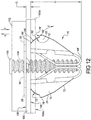
- the purpose of the first, second, third, fourth eyelets 28, 30, 32, 34 will be described in greater detail in reference to Figures 5 and 12 .
- Each of the eyelets 28, 30, 32, 34 includes an eyelet aperture 36 which are all sized to remove a predetermined amount of material of the eyelets 28, 30, 32, 34 to either increase or decrease a bending stiffness of the individual eyelets28, 30, 32, 34.
- both the first and second leg members 16, 20 extend away from a first panel face 38 of planar body panel 14.
- the first and second leg members 16, 20 define mirror images of each other.
- Each of the first and second leg members 16, 20 includes a first leg member portion 40, a second leg member portion 42 positioned outward of first leg member portion 40, and a U-shaped leg member portion 44 which integrally connects the first and second leg member portions 40, 42.
- Each of the first and second leg members 16, 20 also includes multiple retention features, including a first retention feature 46 and a second retention feature 48, which are mirror images of each other.
- First retention feature 46 includes a single tooth first wing 50
- second retention feature 48 includes a single tooth second wing 51.
- first retention feature 46 further includes a multiple tooth first wing 52
- second retention feature 48 includes a multiple tooth second wing 53.
- a curved wing connecting first member 54 integrally connects single tooth first wing 50 to multiple tooth first wing 52.
- a curved wing connecting second member 55 integrally connects single tooth second wing 51 to multiple tooth second wing 53.
- Each of the multiple tooth first and second wings 52, 53 include a plurality of individual teeth each having a successively greater height determined with respect to a curved surface of the first and/or second wings ranging between a lowest height first tooth 56, a second tooth 58 positioned proximate to first tooth 56, a third tooth 60 positioned proximate to second tooth 58, and a highest fourth tooth 62 positioned proximate to third tooth 60.
- Each of the single tooth first wing 50 and single tooth second wing 51 also include a retention tooth which is positioned generally in alignment with respect to fourth tooth 62.
- a first wing retention tooth 64 is provided with single tooth first wing 50
- a second wing retention tooth 66 is provided with single tooth second wing 51.
- Each of the first and second bite members 24, 26 are created such as by a lancing or piercing operation such that the bite members 24, 26 are integrally connected to planar body panel 14 at a first end, and each includes a free end 67 raised from planar body panel 14 with respect to first panel face 38.
- first leg member 16 includes an opening 68 and second leg member 20 includes an oppositely directed opening 70 which are aligned with single helix aperture 22.
- a threaded fastener (shown and described in greater detail in reference to Figures 11 and 12 ), received through single helix aperture 22 can extend entirely between first and second leg members 16, 20 without contacting either of the leg members because of the clearance provided by openings 68, 70.
- Opening 68 further divides U-shaped leg member portion 44 into a portion 44a and a second portion 44b.
- U-shaped leg member portion 44' is similarly divided by opening 70.
- the eyelet aperture 36 for each of the first, second, third, and fourth eyelets 28, 30, 32, 34, such as for fourth eyelet 34 shown, can be varied to change a flange segment width "W" by increasing or decreasing an eyelet aperture diameter "D".
- a flange segment width "W” By changing the flange segment width "W”, the stiffness and therefore the resistance to elastic bending provided by each of the eyelets 28, 30, 32, 34 can be predetermined or tuned.
- a wing-to-wing span "A" of each of the first and second retention features 46, 48 is greatest proximate to the first and second wing retention teeth 64, 66.
- the wing-to-wing span "A” decreases progressively as the first and second retention features 46, 48 approach the U-shaped leg member portions 44. This helps to ensure a centering alignment of fastener 10 when fastener 10 is inserted into a body panel aperture, to be described in greater detail in reference to Figures 10 through 12 .
- a leg spacing "B" is initially provided between first leg member portions 40, 40' of first and second leg members 16, 20.
- first and second leg members 16, 20 may contact each other thereby reducing the leg spacing "B" to zero, which thereafter forces further deflection of the free ends of first and second leg members 16, 20 toward each other.
- a smooth curved surface 72, 72' is provided with each of the single tooth wings such as single tooth second wings 51, 51' shown.
- the single tooth wings 50, 51 are superimposed with respect to the multiple tooth wings 52, 53 (52', 53') when viewed as shown in Figure 5 , and individual teeth of the multiple tooth second wings, such as multiple tooth second wing 53' (not clearly visible in this view), are oriented in a superimposed position and extend further outward with respect to smooth curved surface 72, 72' such that the height of each successive one of the first, second, third, and fourth teeth 56, 58, 60, 62 extends further outward and away with respect to smooth curved surface 72, 72'.
- Each of the first and second leg members 16, 20 further includes a first taper surface 73 for each of the single tooth second wings such as shown for single tooth second wing 51.
- the first taper surface 73 intersects a second taper surface 74 which subsequently intersects a third taper surface 76 proximate to the second wing retention tooth 66.
- a positive engagement surface 78 of each of the second wing retention teeth 66, 66' is oriented substantially parallel with respect to planar body panel 14.
- a leg member free end 79, 79' of the first and second leg members 16, 20 is positioned proximate to planar body panel 14 and is oppositely directed with respect to U-shaped leg member portions 44, 44' toward planar body panel 14. From the non-deflected condition shown, the leg member free ends 79, 79' are elastically deflectable toward each other during installation of fastener 10 by rotation that occurs as a result of bending at the U-shaped leg member portions 44, 44'.
- each of the first, second, third, and fourth eyelets 28, 30, 32, 34 are oriented at an angle ⁇ with respect to a second panel face 80 of planar body panel 14.
- angle ⁇ can range from approximately 5 to15 degrees or more.
- the orientation of eyelets 28, 30, 32, 34 at angle ⁇ predisposes the eyelets 28, 30, 32, 34 for subsequent elastic deflection when the eyelets 28, 30, 32, 34 contact a panel, shown and described in greater detail in reference to Figures 11 and 12 .
- the amount each eyelet 28, 30, 32, 34 will elastically deflect can be tuned to a greater or lesser degree, depending upon the amount of force applied during installation of fastener 10 as the eyelets 28, 30, 32, 34 contact the body panel. For example, by minimizing angle ⁇ and maximizing eyelet aperture diameter "D", the resistance to bending of the eyelets 28, 30, 32, 34 is minimized, or by maximizing angle ⁇ and minimizing eyelet aperture diameter "D", the resistance to bending of each of the eyelets is maximized.
- the geometry of the individual eyelets 28, 30, 32, 34 can therefore be adjusted tuned at the time the tooling for fastener 10 is created to provide for the greatest range of flexibility of the first, second, third, fourth eyelets 28, 30, 32, 34.
- single helix aperture 22 can be formed with single helix aperture 22 substantially centered in planar body panel 14 such that a concave depression 82 and an elongated slot 84 are created.
- Elongated slot 84 defines a thread lead engagement edge 86 to receive a threaded fastener shown and described in greater detail in reference to Figure 12 .
- a raised end portion 88 of single helix aperture 22 is raised with respect to thread lead engagement edge 86.
- the individual single and multiple tooth wings such as single tooth first wing 50' and multiple tooth first wing 52' as shown, can be oriented such that a wing-to-wing orientation angle ⁇ is created.
- wing-to-wing orientation angle ⁇ can range between zero (parallel alignment) to approximately 20 degrees. Wing-to-wing orientation angle ⁇ helps to center fastener 10 in a body panel aperture.
- each of the single tooth wings such as single tooth second wing 51', are defined by a curved surface radius 90.
- each of the first through fourth teeth 56, 58, 60, 62 extend away from a curved surface 91 of the multiple tooth wings, such as multiple tooth second wing 53'.
- Curved surface 91 is defined with respect to a curved surface radius 92 which is substantially equal to curved surface radius 90.
- first leg member 16 also includes a first leg elongated slot 96 which can be sized to increase or decrease the stiffness of first leg member 16.
- second leg elongated slot 98 is provided with second leg member 20 for a similar purpose.
- fastener blank 94 including the individual first, second, third, fourth eyelets 28, 30, 32, 34 plus first and second bite members 24, 26.
- Each of the first, second, third, fourth teeth 56, 58, 60, 62, 64, 66 are also created at this time.
- a coating of a corrosion-resistant material, such as a zinc coating can be applied to the material of fastener blank 94 either before or after the operations to create the individual features of fastener blank 94.
- Other noncorrosive materials can also be substituted for zinc.
- fastener 10 is sized to allow the first and second leg members 16, 20 to elastically deflect toward each other such that the planar body panel 14 of fastener body 12 can be brought into direct contact with a panel 100, such as a vehicle body panel, by inserting the first and second leg members 16, 20 through an aperture 102 created in panel 100.
- aperture 102 has a rectangular shape and includes an aperture length "C" which is greater than an aperture width "E".
- aperture length "C" can be 20.0 millimeters
- aperture width "E” can be 12.8 millimeters.
- fastener 10 is shown immediately prior to installation in the aperture 102 of panel 100.
- a device shown and described in better detail in reference to Figure 12 , can be connected to fastener 10 via a shank 104 threadably received in single helix aperture 22 prior to or after installation of fastener 10. It is noted that shank 104 does not contact either the first or second leg member 16, 20 at any position of its installation; therefore, first leg member portions 40, 40' can contact each other during installation of fastener 10 without interference with shank 104.
- Fastener 10 is oriented having U-shaped leg member portions 44, 44' directed toward panel 100 such that U-shaped leg member portions 44, 44' initially enter aperture 102 first. The first and second leg members 16, 20 subsequently deflect toward each other as they contact an inner wall of aperture 102, until planar body panel 14 contacts panel 100.
- fastener 10 is inserted through aperture 102 until planar body panel 14 contacts a first panel surface 106 of panel 100.
- the height of each of the successive teeth from first through fourth tooth 56 to 62 sequentially increases to permit a maximum rotation of the first and second leg members 16, 20 about an arc of rotation "J" (shown with respect to second leg member 20 or oppositely with respect to first leg member 16) so the minimum number of teeth contact the second panel surface 108 thereby allowing maximum elastic return rotation to a maximum rotated position.
- the maximum rotated position of first and second leg members 16, 20 after insertion into aperture 102 depends on a panel thickness "G" of panel 100.
- Panel 100 can be provided in multiple thicknesses, as is known, which range from a minimum thickness shown of approximately 0.65 millimeters to a maximum panel thickness of a panel 100a of approximately 2.5 millimeters. In the installed position, individual ones of the first through fourth teeth 56, 58, 60, 62 contact a second panel surface such as a second panel surface 108 of the minimum thickness panel 100, or a second panel surface 108a of maximum thickness panel 100a.
- a fastener extending length "H" can therefore vary depending upon the thickness of panel 100.
- the teeth which contact the second panel surface 108 of panel 100 act to resist release of fastener 10 in a release direction "K".
- fastener 10 can be inserted with as little as 45 newton meters of force.
- a maximum resistance to release of fastener 10 of approximately 1,780 newton meters is provided by contact between positive engagement surface 78 to second panel surface 108.
- a connection fastener head 110 integrally connected to shank 104, provides a positive engagement feature to retain a mounted device 112 with respect to first panel surface 106.
- Mounted device 112 can include a plurality of different devices including but not limited to vehicle trim members, manual hand grabs, sun visors, and the like.
- the purpose for smooth curved surface 72 is to provide a common base surface between the individual teeth of multiple tooth first and second wings 52, 53. If a panel thickness "G" results in contact between the first or second leg members 16, 20 and the second panel surface 108 in between any of the teeth, contact will be made with smooth curved surface 72, providing frictional contact to resist removal of fastener 10 until contact with the positive engagement surface 78 is made.
- the individual eyelets including first, second, third, fourth eyelets 28, 30, 32, 34 (only first and second eyelets 28, 30 are visible in this view), elastically deform to position each of the eyelets 28, 30, 32, 34 substantially parallel with respect to first panel surface 106 in the installed position of fastener 10. It is also possible that planar body panel 14 can be raised with respect to first panel surface 106 if the individual eyelets 28, 30, 32, 34 do not completely deflect during installation of fastener 10. Another purpose of the individual eyelets 28, 30, 32, 34 is to broaden the footprint, or surface area, of planar body panel 14 of fastener 10 which is in direct contact with first panel surface 106.
- planar body panel 14 can be raised with respect to first panel surface 106 by contact between the first and second bite members 24, 26 and first panel surface 106 when first and second bite members 24, 26 are present.
- First and second bite members 24, 26 when engaging the first panel surface 106 act to prevent rotation of fastener 10 when shank 104 is rotatably received in single helix aperture 22.
- single helix aperture 22 can be replaced by a double helix aperture, and first and second bite members 24, 26 can be increased in quantity or omitted.
- quantity of teeth of multiple tooth wings 52, 52', 53, 53'
- the material of fastener 10 can also be a polymeric material in place of metal, and fastener 10 can be made using a molding operation and molding die, however, the maximum resistance to release of 1,780 newton meters may not be achieved with a polymeric material.
- retention fastener 10 includes body panel 14 having first and second leg members 16, 20 integrally connected to the body panel 14 and both co-extending with respect to the first panel surface 106 of the body panel 14.
- Each of the first and second leg members includes at least one retention feature 46, 48, including single tooth wing (50, 51) having smooth curved surface 72 extending to a single wing retention tooth (64, 66).
- Multiple tooth wing (52, 53) is positioned beside the single tooth wing (50, 51), with the multiple tooth wing (52, 53) having multiple individual teeth (56, 58, 60, 62) arranged on curved surface 91.
- the multiple tooth wing (52, 53) is oriented in a superimposed position (as shown in Figures 5 and 12 ) with respect to the single tooth wing (50, 51) such that the individual teeth (56, 58, 60, 62) extend outwardly with respect to the smooth curved surface 72 of the single tooth wing (50, 51).
- the individual teeth (56, 58, 60, 62) of the at least one retention feature 46, 48 of the first leg member 16 are oppositely directed with respect to the individual teeth (56', 58', 60', 62') of the at least one retention feature 46', 48' of the second leg member 20.
- a retention fastener system 105 includes panel 100 having aperture 102 created therethrough.
- the panel 100 has opposed first and second panel surfaces 106, 108.
- Fastener 10 is adapted to partially extend through the aperture 102 of the panel 100.
- the fastener 10 includes body panel 14 which contacts the first panel surface 106 in a fastener installed position.
- First and second leg members 16, 20 of fastener 10 are integrally connected to the body panel 14 by first leg member portions 40, 40' and both co-extend with respect to first panel face 38 of body panel 14, and have a second leg member portion 42, 42' directed back toward the body panel 14.
- Each of the first and second leg members 16, 20 includes at least one retention feature 46, 48 (46', 48') connected to the second leg member portion 40 or 40'.
- the at least one retention feature 46, 48 includes single tooth wing 50, 51 (50', 51') having smooth curved surface 72, 72' extending to single wing retention tooth 64, 66 (64', 66') and multiple tooth wing 52, 53 (52', 53') positioned beside the single tooth wing 50, 51 (50', 51').
- the multiple tooth wing 52, 53 (52', 53') has multiple individual teeth 56, 58, 60, 62 (56', 58', 60', 62') arranged on curved surface 91, 91' that sequentially increase in height with respect to the curved surface 91, 91'.
- the multiple tooth wing 52, 53 (52', 53') is oriented in a superimposed position with respect to the single tooth wing 50, 51 (50', 51') such that the individual teeth 56, 58, 60, 62 (56', 58', 60', 62') extend outwardly with respect to the smooth curved surface 72, 72' of the single tooth wing 50, 51 (50', 51').
- the first and second leg members 16, 20 extend through the aperture 102 in the fastener installed position (shown in Figure 12 ) and have an individual one 56, 58, 60, or 62 (56', 58', 60', or 62') of the individual teeth 56, 58, 60, 62 (56', 58', 60', 62') of the multiple tooth wing 52, 53 (52', 53') and the smooth curved surface 72, 72' of the single tooth wing 50, 51 (50', 51') of both the first and second leg members 16, 20 contacting the second panel surface 108.
- Example embodiments are provided so that this disclosure will be thorough, and will fully convey the scope to those who are skilled in the art. Numerous specific details are set forth such as examples of specific components, devices, and methods, to provide a thorough understanding of embodiments of the present disclosure. It will be apparent to those skilled in the art that specific details need not be employed, that example embodiments may be embodied in many different forms and that neither should be construed to limit the scope of the disclosure. In some example embodiments, well-known processes, well-known device structures, and well-known technologies are not described in detail.
- first, second, third, etc. may be used herein to describe various elements, components, regions, layers and/or sections, these elements, components, regions, layers and/or sections should not be limited by these terms. These terms may be only used to distinguish one element, component, region, layer or section from another region, layer or section. Terms such as “first,” “second,” and other numerical terms when used herein do not imply a sequence or order unless clearly indicated by the context. Thus, a first element, component, region, layer or section discussed below could be termed a second element, component, region, layer or section without departing from the teachings of the example embodiments.
- spatially relative terms such as “inner,” “outer,” “beneath,” “below,” “lower,” “above,” “upper,” and the like, may be used herein for ease of description to describe one element or feature's relationship to another element(s) or feature(s) as illustrated in the figures.
- Spatially relative terms may be intended to encompass different orientations of the device in use or operation in addition to the orientation depicted in the figures. For example, if the device in the figures is turned over, elements described as “below” or “beneath” other elements or features would then be oriented “above” the other elements or features.
- the example term “below” can encompass both an orientation of above and below.
- the device may be otherwise oriented (rotated 90 degrees or at other orientations) and the spatially relative descriptors used herein interpreted accordingly.
Landscapes
- Engineering & Computer Science (AREA)
- General Engineering & Computer Science (AREA)
- Mechanical Engineering (AREA)
- Connection Of Plates (AREA)
- Slide Fasteners, Snap Fasteners, And Hook Fasteners (AREA)
Priority Applications (1)
| Application Number | Priority Date | Filing Date | Title |
|---|---|---|---|
| PL13165269T PL2657543T3 (pl) | 2012-04-27 | 2013-04-25 | Łącznik o wysokim stopniu przytrzymywania |
Applications Claiming Priority (1)
| Application Number | Priority Date | Filing Date | Title |
|---|---|---|---|
| US13/458,043 US8800120B2 (en) | 2012-04-27 | 2012-04-27 | High retention fastener |
Publications (3)
| Publication Number | Publication Date |
|---|---|
| EP2657543A2 EP2657543A2 (en) | 2013-10-30 |
| EP2657543A3 EP2657543A3 (en) | 2017-01-18 |
| EP2657543B1 true EP2657543B1 (en) | 2018-06-20 |
Family
ID=48193119
Family Applications (1)
| Application Number | Title | Priority Date | Filing Date |
|---|---|---|---|
| EP13165269.5A Not-in-force EP2657543B1 (en) | 2012-04-27 | 2013-04-25 | High retention fastener |
Country Status (3)
| Country | Link |
|---|---|
| US (1) | US8800120B2 (pl) |
| EP (1) | EP2657543B1 (pl) |
| PL (1) | PL2657543T3 (pl) |
Families Citing this family (23)
| Publication number | Priority date | Publication date | Assignee | Title |
|---|---|---|---|---|
| US11261897B2 (en) * | 2003-11-17 | 2022-03-01 | Mag Daddy, LLC | Structural fastener |
| US11815206B2 (en) * | 2004-09-16 | 2023-11-14 | Mag Daddy Llc | Structural fastener |
| US11784428B2 (en) * | 2018-08-20 | 2023-10-10 | Mag Daddy Llc | Structural fastener |
| US9919674B2 (en) * | 2012-02-14 | 2018-03-20 | Termax Llc | Tethered fastener apparatus and method |
| US9097270B2 (en) * | 2013-07-26 | 2015-08-04 | GM Global Technology Operations LLC | Snap fit fastener |
| WO2016094795A1 (en) | 2014-12-11 | 2016-06-16 | A.K. Stamping Company, Inc. | Grounding clamps |
| DE102017214910A1 (de) * | 2017-08-25 | 2019-02-28 | Siemens Mobility GmbH | Sicherungselement und Verliersicherungssystem |
| CN109578419A (zh) * | 2017-09-29 | 2019-04-05 | 长城汽车股份有限公司 | 螺母结构、护板与横梁总成及其制备方法 |
| US11629742B2 (en) * | 2018-06-19 | 2023-04-18 | Illinois Tool Works Inc. | Box nut retainer |
| USD874913S1 (en) * | 2018-06-19 | 2020-02-11 | Illinois Tool Works Inc. | Nut retainer |
| US11619324B2 (en) * | 2018-08-20 | 2023-04-04 | Mag Daddy, LLC | Structural fastener |
| US11951915B2 (en) * | 2019-04-22 | 2024-04-09 | Termax Company | Fastener clip with push nut |
| US11692581B2 (en) | 2019-08-22 | 2023-07-04 | Illinois Tool Works Inc. | Box nut retainer |
| USD904866S1 (en) | 2019-08-23 | 2020-12-15 | Illinois Tool Works Inc. | Nut retainer |
| USD888546S1 (en) * | 2019-08-23 | 2020-06-30 | Illinois Tool Works Inc. | Nut retainer |
| USD904865S1 (en) | 2019-08-23 | 2020-12-15 | Illinois Tool Works Inc. | Nut retainer |
| US20210062855A1 (en) * | 2019-08-27 | 2021-03-04 | Illinois Tool Works Inc. | Ergonomic Box Nut Retainer |
| US20220001936A1 (en) * | 2020-07-06 | 2022-01-06 | Ford Global Technologies, Llc | Retention assemblies for automotive vehicles |
| USD1028701S1 (en) * | 2020-10-19 | 2024-05-28 | Illinois Tool Works Inc. | Nut |
| USD1029627S1 (en) * | 2020-12-23 | 2024-06-04 | Jonathan Winnie | Magnetic hook |
| US12049916B2 (en) * | 2021-02-05 | 2024-07-30 | Erico International Corporation | Spring nut |
| DE102023105023B3 (de) * | 2023-03-01 | 2024-05-23 | Grammer Aktiengesellschaft | Halteklammer |
| US12519294B1 (en) | 2023-03-16 | 2026-01-06 | Titan3 Technology LLC | Cable clamp for electrical junction box |
Family Cites Families (21)
| Publication number | Priority date | Publication date | Assignee | Title |
|---|---|---|---|---|
| DE69615118T2 (de) * | 1995-09-19 | 2002-06-27 | Daiwa Kasei Kogyo K.K., Okazaki | Schenkel zur Befestigung eines Komponentes |
| US5919019A (en) * | 1998-01-20 | 1999-07-06 | California Industrial Products, Inc. | Mid-panel nut |
| US7168138B2 (en) | 2000-03-27 | 2007-01-30 | Newfrey Llc | Resilient clip fastener |
| US9457734B2 (en) * | 2001-06-25 | 2016-10-04 | Termax Corporation | Continuously adaptive fastener clip |
| US6718599B2 (en) * | 2001-06-25 | 2004-04-13 | Termax Corporation | Spring fastener with ergonomically balanced removal to insertion force ratio |
| WO2003046393A1 (en) | 2001-11-21 | 2003-06-05 | Newfrey Llc | Plastic retaining clip for rib attachment |
| US7066701B2 (en) | 2002-02-07 | 2006-06-27 | Newfrey Llc | Fastener for variously sized studs |
| JP2004044644A (ja) | 2002-07-10 | 2004-02-12 | Nippon Pop Rivets & Fasteners Ltd | スクリューグロメット |
| DE10357024A1 (de) | 2003-12-03 | 2005-06-30 | Newfrey Llc, Newark | Befestigungselement zur Anbringung auf einem Gewindebolzen |
| US6824197B2 (en) | 2003-03-20 | 2004-11-30 | Newfrey Llc | Panel retention device |
| US7179013B2 (en) | 2003-05-30 | 2007-02-20 | Newfrey Llc | Self centering sill plate retainer with opposing wings |
| US7188392B2 (en) * | 2003-11-17 | 2007-03-13 | Termax Corporation | Spring fastener with highly improved lever/angle pulling force |
| US7086125B2 (en) | 2004-04-23 | 2006-08-08 | Newfrey Llc | Multiple stage assembly assist fastener |
| JP4357374B2 (ja) | 2004-06-28 | 2009-11-04 | ポップリベット・ファスナー株式会社 | パイプ等の耐熱性クランプ装置 |
| EP2182226B1 (de) * | 2006-04-26 | 2012-07-25 | A. Raymond et Cie. | Befestigungsvorrichtung |
| DE102006052499A1 (de) | 2006-11-06 | 2008-05-08 | Newfrey Llc, Newark | Schelle aus Kunststoff |
| DE102007042034A1 (de) | 2007-09-05 | 2009-03-12 | Newfrey Llc, Newark | Befestigungssystem zum Befestigen von Bauelementen, insbesondere für Kraftfahrzeuge |
| US7900953B2 (en) | 2008-02-15 | 2011-03-08 | Newfrey Llc | Two stage high retention fastener |
| DE202009015837U1 (de) | 2009-11-20 | 2010-02-18 | Newfrey Llc, Newark | Bolzen und Befestigungsvorrichtung mit Bolzen und flexiblem Clip |
| JP5478374B2 (ja) | 2010-06-15 | 2014-04-23 | ポップリベット・ファスナー株式会社 | 結束具 |
| DE202010008001U1 (de) | 2010-07-07 | 2010-09-02 | Newfrey Llc, Newark | Clip zur Befestigung einer Leiste oder Rippe |
-
2012
- 2012-04-27 US US13/458,043 patent/US8800120B2/en not_active Expired - Fee Related
-
2013
- 2013-04-25 EP EP13165269.5A patent/EP2657543B1/en not_active Not-in-force
- 2013-04-25 PL PL13165269T patent/PL2657543T3/pl unknown
Non-Patent Citations (1)
| Title |
|---|
| None * |
Also Published As
| Publication number | Publication date |
|---|---|
| PL2657543T3 (pl) | 2018-12-31 |
| US20130287521A1 (en) | 2013-10-31 |
| EP2657543A3 (en) | 2017-01-18 |
| EP2657543A2 (en) | 2013-10-30 |
| US8800120B2 (en) | 2014-08-12 |
Similar Documents
| Publication | Publication Date | Title |
|---|---|---|
| EP2657543B1 (en) | High retention fastener | |
| EP4242475B1 (en) | Dual component u-base fastener | |
| DE10119063B4 (de) | Nietmutterbaueinheit | |
| DE102016201103B4 (de) | Kontaktteil | |
| EP2734738B1 (de) | Bauteilverbindung sowie verfahren zum verbinden zweier bauteile | |
| CA2073731C (en) | Captivating a fastener to a workpiece | |
| EP1939467A2 (en) | Over-molded compression limiter | |
| EP2481939B1 (de) | Spannschelle | |
| EP1507981A1 (en) | Resilient clip fastener and method of manufacturing the same | |
| EP3696428B1 (en) | Fastener clip with stabilizing shoulder tabs | |
| EP2613062B1 (en) | Shielding and insulation fastener | |
| DE102013018113A1 (de) | Clipmutter | |
| EP2778442A2 (en) | Fastening method and apparatus | |
| US20130081255A1 (en) | Retainer - spring steel single thread engagement | |
| US10047783B2 (en) | Flex reduction clip nut | |
| US11761468B2 (en) | Stud clip assembly and method | |
| DE102012109059A1 (de) | Halterung eines Leuchtmittels in der Öffnung eines Reflektors | |
| DE102007048298A1 (de) | Befestigungsvorrichtung | |
| US20130272778A1 (en) | Fascia bracket mounting system - captive floating nut system to weld stud | |
| US11428256B2 (en) | Fastener for thin sheet material | |
| US20210003167A1 (en) | Insert nut | |
| EP1941180B1 (de) | Halter für längliche, flexible objekte wie seilzüge | |
| DE102014208789A1 (de) | Schwingungsdämpfer | |
| WO2018140114A1 (en) | Retention clip with anti-rotation feature | |
| DE102013211961A1 (de) | Verbindungseinheit zum Verbinden zweier Bauteile, insbesondere von Gehäuseteilen, und ein Verfahren zur Herstellung einer Verbindung zwischen zwei Bauteilen über eine Verbindungseinheit |
Legal Events
| Date | Code | Title | Description |
|---|---|---|---|
| PUAI | Public reference made under article 153(3) epc to a published international application that has entered the european phase |
Free format text: ORIGINAL CODE: 0009012 |
|
| AK | Designated contracting states |
Kind code of ref document: A2 Designated state(s): AL AT BE BG CH CY CZ DE DK EE ES FI FR GB GR HR HU IE IS IT LI LT LU LV MC MK MT NL NO PL PT RO RS SE SI SK SM TR |
|
| AX | Request for extension of the european patent |
Extension state: BA ME |
|
| RAP1 | Party data changed (applicant data changed or rights of an application transferred) |
Owner name: NEWFREY LLC |
|
| PUAL | Search report despatched |
Free format text: ORIGINAL CODE: 0009013 |
|
| AK | Designated contracting states |
Kind code of ref document: A3 Designated state(s): AL AT BE BG CH CY CZ DE DK EE ES FI FR GB GR HR HU IE IS IT LI LT LU LV MC MK MT NL NO PL PT RO RS SE SI SK SM TR |
|
| AX | Request for extension of the european patent |
Extension state: BA ME |
|
| RIC1 | Information provided on ipc code assigned before grant |
Ipc: F16B 5/06 20060101AFI20161214BHEP Ipc: F16B 37/04 20060101ALI20161214BHEP |
|
| STAA | Information on the status of an ep patent application or granted ep patent |
Free format text: STATUS: REQUEST FOR EXAMINATION WAS MADE |
|
| 17P | Request for examination filed |
Effective date: 20170703 |
|
| RBV | Designated contracting states (corrected) |
Designated state(s): AL AT BE BG CH CY CZ DE DK EE ES FI FR GB GR HR HU IE IS IT LI LT LU LV MC MK MT NL NO PL PT RO RS SE SI SK SM TR |
|
| GRAP | Despatch of communication of intention to grant a patent |
Free format text: ORIGINAL CODE: EPIDOSNIGR1 |
|
| STAA | Information on the status of an ep patent application or granted ep patent |
Free format text: STATUS: GRANT OF PATENT IS INTENDED |
|
| INTG | Intention to grant announced |
Effective date: 20180105 |
|
| GRAS | Grant fee paid |
Free format text: ORIGINAL CODE: EPIDOSNIGR3 |
|
| GRAA | (expected) grant |
Free format text: ORIGINAL CODE: 0009210 |
|
| STAA | Information on the status of an ep patent application or granted ep patent |
Free format text: STATUS: THE PATENT HAS BEEN GRANTED |
|
| AK | Designated contracting states |
Kind code of ref document: B1 Designated state(s): AL AT BE BG CH CY CZ DE DK EE ES FI FR GB GR HR HU IE IS IT LI LT LU LV MC MK MT NL NO PL PT RO RS SE SI SK SM TR |
|
| REG | Reference to a national code |
Ref country code: GB Ref legal event code: FG4D |
|
| REG | Reference to a national code |
Ref country code: IE Ref legal event code: FG4D |
|
| REG | Reference to a national code |
Ref country code: AT Ref legal event code: REF Ref document number: 1010798 Country of ref document: AT Kind code of ref document: T Effective date: 20180715 |
|
| REG | Reference to a national code |
Ref country code: DE Ref legal event code: R096 Ref document number: 602013039103 Country of ref document: DE |
|
| REG | Reference to a national code |
Ref country code: NL Ref legal event code: MP Effective date: 20180620 |
|
| PG25 | Lapsed in a contracting state [announced via postgrant information from national office to epo] |
Ref country code: LT Free format text: LAPSE BECAUSE OF FAILURE TO SUBMIT A TRANSLATION OF THE DESCRIPTION OR TO PAY THE FEE WITHIN THE PRESCRIBED TIME-LIMIT Effective date: 20180620 Ref country code: SE Free format text: LAPSE BECAUSE OF FAILURE TO SUBMIT A TRANSLATION OF THE DESCRIPTION OR TO PAY THE FEE WITHIN THE PRESCRIBED TIME-LIMIT Effective date: 20180620 Ref country code: FI Free format text: LAPSE BECAUSE OF FAILURE TO SUBMIT A TRANSLATION OF THE DESCRIPTION OR TO PAY THE FEE WITHIN THE PRESCRIBED TIME-LIMIT Effective date: 20180620 Ref country code: BG Free format text: LAPSE BECAUSE OF FAILURE TO SUBMIT A TRANSLATION OF THE DESCRIPTION OR TO PAY THE FEE WITHIN THE PRESCRIBED TIME-LIMIT Effective date: 20180920 Ref country code: NO Free format text: LAPSE BECAUSE OF FAILURE TO SUBMIT A TRANSLATION OF THE DESCRIPTION OR TO PAY THE FEE WITHIN THE PRESCRIBED TIME-LIMIT Effective date: 20180920 |
|
| REG | Reference to a national code |
Ref country code: LT Ref legal event code: MG4D |
|
| PG25 | Lapsed in a contracting state [announced via postgrant information from national office to epo] |
Ref country code: LV Free format text: LAPSE BECAUSE OF FAILURE TO SUBMIT A TRANSLATION OF THE DESCRIPTION OR TO PAY THE FEE WITHIN THE PRESCRIBED TIME-LIMIT Effective date: 20180620 Ref country code: GR Free format text: LAPSE BECAUSE OF FAILURE TO SUBMIT A TRANSLATION OF THE DESCRIPTION OR TO PAY THE FEE WITHIN THE PRESCRIBED TIME-LIMIT Effective date: 20180921 Ref country code: HR Free format text: LAPSE BECAUSE OF FAILURE TO SUBMIT A TRANSLATION OF THE DESCRIPTION OR TO PAY THE FEE WITHIN THE PRESCRIBED TIME-LIMIT Effective date: 20180620 Ref country code: RS Free format text: LAPSE BECAUSE OF FAILURE TO SUBMIT A TRANSLATION OF THE DESCRIPTION OR TO PAY THE FEE WITHIN THE PRESCRIBED TIME-LIMIT Effective date: 20180620 |
|
| REG | Reference to a national code |
Ref country code: AT Ref legal event code: MK05 Ref document number: 1010798 Country of ref document: AT Kind code of ref document: T Effective date: 20180620 |
|
| PG25 | Lapsed in a contracting state [announced via postgrant information from national office to epo] |
Ref country code: NL Free format text: LAPSE BECAUSE OF FAILURE TO SUBMIT A TRANSLATION OF THE DESCRIPTION OR TO PAY THE FEE WITHIN THE PRESCRIBED TIME-LIMIT Effective date: 20180620 |
|
| PG25 | Lapsed in a contracting state [announced via postgrant information from national office to epo] |
Ref country code: AT Free format text: LAPSE BECAUSE OF FAILURE TO SUBMIT A TRANSLATION OF THE DESCRIPTION OR TO PAY THE FEE WITHIN THE PRESCRIBED TIME-LIMIT Effective date: 20180620 Ref country code: RO Free format text: LAPSE BECAUSE OF FAILURE TO SUBMIT A TRANSLATION OF THE DESCRIPTION OR TO PAY THE FEE WITHIN THE PRESCRIBED TIME-LIMIT Effective date: 20180620 Ref country code: CZ Free format text: LAPSE BECAUSE OF FAILURE TO SUBMIT A TRANSLATION OF THE DESCRIPTION OR TO PAY THE FEE WITHIN THE PRESCRIBED TIME-LIMIT Effective date: 20180620 Ref country code: SK Free format text: LAPSE BECAUSE OF FAILURE TO SUBMIT A TRANSLATION OF THE DESCRIPTION OR TO PAY THE FEE WITHIN THE PRESCRIBED TIME-LIMIT Effective date: 20180620 Ref country code: EE Free format text: LAPSE BECAUSE OF FAILURE TO SUBMIT A TRANSLATION OF THE DESCRIPTION OR TO PAY THE FEE WITHIN THE PRESCRIBED TIME-LIMIT Effective date: 20180620 Ref country code: IS Free format text: LAPSE BECAUSE OF FAILURE TO SUBMIT A TRANSLATION OF THE DESCRIPTION OR TO PAY THE FEE WITHIN THE PRESCRIBED TIME-LIMIT Effective date: 20181020 |
|
| PG25 | Lapsed in a contracting state [announced via postgrant information from national office to epo] |
Ref country code: ES Free format text: LAPSE BECAUSE OF FAILURE TO SUBMIT A TRANSLATION OF THE DESCRIPTION OR TO PAY THE FEE WITHIN THE PRESCRIBED TIME-LIMIT Effective date: 20180620 Ref country code: SM Free format text: LAPSE BECAUSE OF FAILURE TO SUBMIT A TRANSLATION OF THE DESCRIPTION OR TO PAY THE FEE WITHIN THE PRESCRIBED TIME-LIMIT Effective date: 20180620 |
|
| REG | Reference to a national code |
Ref country code: DE Ref legal event code: R097 Ref document number: 602013039103 Country of ref document: DE |
|
| PLBE | No opposition filed within time limit |
Free format text: ORIGINAL CODE: 0009261 |
|
| STAA | Information on the status of an ep patent application or granted ep patent |
Free format text: STATUS: NO OPPOSITION FILED WITHIN TIME LIMIT |
|
| 26N | No opposition filed |
Effective date: 20190321 |
|
| PG25 | Lapsed in a contracting state [announced via postgrant information from national office to epo] |
Ref country code: DK Free format text: LAPSE BECAUSE OF FAILURE TO SUBMIT A TRANSLATION OF THE DESCRIPTION OR TO PAY THE FEE WITHIN THE PRESCRIBED TIME-LIMIT Effective date: 20180620 |
|
| PG25 | Lapsed in a contracting state [announced via postgrant information from national office to epo] |
Ref country code: SI Free format text: LAPSE BECAUSE OF FAILURE TO SUBMIT A TRANSLATION OF THE DESCRIPTION OR TO PAY THE FEE WITHIN THE PRESCRIBED TIME-LIMIT Effective date: 20180620 |
|
| PG25 | Lapsed in a contracting state [announced via postgrant information from national office to epo] |
Ref country code: AL Free format text: LAPSE BECAUSE OF FAILURE TO SUBMIT A TRANSLATION OF THE DESCRIPTION OR TO PAY THE FEE WITHIN THE PRESCRIBED TIME-LIMIT Effective date: 20180620 |
|
| REG | Reference to a national code |
Ref country code: CH Ref legal event code: PL |
|
| REG | Reference to a national code |
Ref country code: BE Ref legal event code: MM Effective date: 20190430 |
|
| GBPC | Gb: european patent ceased through non-payment of renewal fee |
Effective date: 20190425 |
|
| PG25 | Lapsed in a contracting state [announced via postgrant information from national office to epo] |
Ref country code: LU Free format text: LAPSE BECAUSE OF NON-PAYMENT OF DUE FEES Effective date: 20190425 Ref country code: MC Free format text: LAPSE BECAUSE OF FAILURE TO SUBMIT A TRANSLATION OF THE DESCRIPTION OR TO PAY THE FEE WITHIN THE PRESCRIBED TIME-LIMIT Effective date: 20180620 |
|
| PG25 | Lapsed in a contracting state [announced via postgrant information from national office to epo] |
Ref country code: LI Free format text: LAPSE BECAUSE OF NON-PAYMENT OF DUE FEES Effective date: 20190430 Ref country code: GB Free format text: LAPSE BECAUSE OF NON-PAYMENT OF DUE FEES Effective date: 20190425 Ref country code: CH Free format text: LAPSE BECAUSE OF NON-PAYMENT OF DUE FEES Effective date: 20190430 |
|
| PG25 | Lapsed in a contracting state [announced via postgrant information from national office to epo] |
Ref country code: BE Free format text: LAPSE BECAUSE OF NON-PAYMENT OF DUE FEES Effective date: 20190430 Ref country code: FR Free format text: LAPSE BECAUSE OF NON-PAYMENT OF DUE FEES Effective date: 20190430 |
|
| PG25 | Lapsed in a contracting state [announced via postgrant information from national office to epo] |
Ref country code: TR Free format text: LAPSE BECAUSE OF FAILURE TO SUBMIT A TRANSLATION OF THE DESCRIPTION OR TO PAY THE FEE WITHIN THE PRESCRIBED TIME-LIMIT Effective date: 20180620 |
|
| PG25 | Lapsed in a contracting state [announced via postgrant information from national office to epo] |
Ref country code: IE Free format text: LAPSE BECAUSE OF NON-PAYMENT OF DUE FEES Effective date: 20190425 |
|
| PG25 | Lapsed in a contracting state [announced via postgrant information from national office to epo] |
Ref country code: PT Free format text: LAPSE BECAUSE OF FAILURE TO SUBMIT A TRANSLATION OF THE DESCRIPTION OR TO PAY THE FEE WITHIN THE PRESCRIBED TIME-LIMIT Effective date: 20181022 |
|
| PGFP | Annual fee paid to national office [announced via postgrant information from national office to epo] |
Ref country code: IT Payment date: 20210310 Year of fee payment: 9 |
|
| PG25 | Lapsed in a contracting state [announced via postgrant information from national office to epo] |
Ref country code: CY Free format text: LAPSE BECAUSE OF FAILURE TO SUBMIT A TRANSLATION OF THE DESCRIPTION OR TO PAY THE FEE WITHIN THE PRESCRIBED TIME-LIMIT Effective date: 20180620 |
|
| PGFP | Annual fee paid to national office [announced via postgrant information from national office to epo] |
Ref country code: PL Payment date: 20210301 Year of fee payment: 9 |
|
| PG25 | Lapsed in a contracting state [announced via postgrant information from national office to epo] |
Ref country code: HU Free format text: LAPSE BECAUSE OF FAILURE TO SUBMIT A TRANSLATION OF THE DESCRIPTION OR TO PAY THE FEE WITHIN THE PRESCRIBED TIME-LIMIT; INVALID AB INITIO Effective date: 20130425 Ref country code: MT Free format text: LAPSE BECAUSE OF FAILURE TO SUBMIT A TRANSLATION OF THE DESCRIPTION OR TO PAY THE FEE WITHIN THE PRESCRIBED TIME-LIMIT Effective date: 20180620 |
|
| PGFP | Annual fee paid to national office [announced via postgrant information from national office to epo] |
Ref country code: DE Payment date: 20210330 Year of fee payment: 9 |
|
| PG25 | Lapsed in a contracting state [announced via postgrant information from national office to epo] |
Ref country code: MK Free format text: LAPSE BECAUSE OF FAILURE TO SUBMIT A TRANSLATION OF THE DESCRIPTION OR TO PAY THE FEE WITHIN THE PRESCRIBED TIME-LIMIT Effective date: 20180620 |
|
| REG | Reference to a national code |
Ref country code: DE Ref legal event code: R119 Ref document number: 602013039103 Country of ref document: DE |
|
| PG25 | Lapsed in a contracting state [announced via postgrant information from national office to epo] |
Ref country code: DE Free format text: LAPSE BECAUSE OF NON-PAYMENT OF DUE FEES Effective date: 20221103 |
|
| PG25 | Lapsed in a contracting state [announced via postgrant information from national office to epo] |
Ref country code: IT Free format text: LAPSE BECAUSE OF NON-PAYMENT OF DUE FEES Effective date: 20220425 |
|
| PG25 | Lapsed in a contracting state [announced via postgrant information from national office to epo] |
Ref country code: PL Free format text: LAPSE BECAUSE OF NON-PAYMENT OF DUE FEES Effective date: 20220425 |