EP2657555A2 - Leichte Hochleistungskugellager zur Vibrationsunterdrückung in der Luft - Google Patents
Leichte Hochleistungskugellager zur Vibrationsunterdrückung in der Luft Download PDFInfo
- Publication number
- EP2657555A2 EP2657555A2 EP13165655.5A EP13165655A EP2657555A2 EP 2657555 A2 EP2657555 A2 EP 2657555A2 EP 13165655 A EP13165655 A EP 13165655A EP 2657555 A2 EP2657555 A2 EP 2657555A2
- Authority
- EP
- European Patent Office
- Prior art keywords
- rolling elements
- race
- disposed
- radius
- bearing
- Prior art date
- Legal status (The legal status is an assumption and is not a legal conclusion. Google has not performed a legal analysis and makes no representation as to the accuracy of the status listed.)
- Withdrawn
Links
- 230000001629 suppression Effects 0.000 title claims abstract description 12
- 238000005096 rolling process Methods 0.000 claims abstract description 113
- 239000000463 material Substances 0.000 claims description 4
- 239000013585 weight reducing agent Substances 0.000 description 4
- 239000004696 Poly ether ether ketone Substances 0.000 description 2
- 239000004033 plastic Substances 0.000 description 2
- 229920003023 plastic Polymers 0.000 description 2
- 229920002530 polyetherether ketone Polymers 0.000 description 2
- 229920001343 polytetrafluoroethylene Polymers 0.000 description 2
- 239000004810 polytetrafluoroethylene Substances 0.000 description 2
- 241000237858 Gastropoda Species 0.000 description 1
- 239000004642 Polyimide Substances 0.000 description 1
- 238000012986 modification Methods 0.000 description 1
- 230000004048 modification Effects 0.000 description 1
- 229920001721 polyimide Polymers 0.000 description 1
- -1 polytetrafluoroethylene Polymers 0.000 description 1
Images


Classifications
-
- F—MECHANICAL ENGINEERING; LIGHTING; HEATING; WEAPONS; BLASTING
- F16—ENGINEERING ELEMENTS AND UNITS; GENERAL MEASURES FOR PRODUCING AND MAINTAINING EFFECTIVE FUNCTIONING OF MACHINES OR INSTALLATIONS; THERMAL INSULATION IN GENERAL
- F16C—SHAFTS; FLEXIBLE SHAFTS; ELEMENTS OR CRANKSHAFT MECHANISMS; ROTARY BODIES OTHER THAN GEARING ELEMENTS; BEARINGS
- F16C19/00—Bearings with rolling contact, for exclusively rotary movement
- F16C19/22—Bearings with rolling contact, for exclusively rotary movement with bearing rollers essentially of the same size in one or more circular rows, e.g. needle bearings
- F16C19/24—Bearings with rolling contact, for exclusively rotary movement with bearing rollers essentially of the same size in one or more circular rows, e.g. needle bearings for radial load mainly
- F16C19/28—Bearings with rolling contact, for exclusively rotary movement with bearing rollers essentially of the same size in one or more circular rows, e.g. needle bearings for radial load mainly with two or more rows of rollers
-
- F—MECHANICAL ENGINEERING; LIGHTING; HEATING; WEAPONS; BLASTING
- F16—ENGINEERING ELEMENTS AND UNITS; GENERAL MEASURES FOR PRODUCING AND MAINTAINING EFFECTIVE FUNCTIONING OF MACHINES OR INSTALLATIONS; THERMAL INSULATION IN GENERAL
- F16C—SHAFTS; FLEXIBLE SHAFTS; ELEMENTS OR CRANKSHAFT MECHANISMS; ROTARY BODIES OTHER THAN GEARING ELEMENTS; BEARINGS
- F16C19/00—Bearings with rolling contact, for exclusively rotary movement
- F16C19/02—Bearings with rolling contact, for exclusively rotary movement with bearing balls essentially of the same size in one or more circular rows
- F16C19/04—Bearings with rolling contact, for exclusively rotary movement with bearing balls essentially of the same size in one or more circular rows for radial load mainly
- F16C19/08—Bearings with rolling contact, for exclusively rotary movement with bearing balls essentially of the same size in one or more circular rows for radial load mainly with two or more rows of balls
-
- F—MECHANICAL ENGINEERING; LIGHTING; HEATING; WEAPONS; BLASTING
- F16—ENGINEERING ELEMENTS AND UNITS; GENERAL MEASURES FOR PRODUCING AND MAINTAINING EFFECTIVE FUNCTIONING OF MACHINES OR INSTALLATIONS; THERMAL INSULATION IN GENERAL
- F16C—SHAFTS; FLEXIBLE SHAFTS; ELEMENTS OR CRANKSHAFT MECHANISMS; ROTARY BODIES OTHER THAN GEARING ELEMENTS; BEARINGS
- F16C19/00—Bearings with rolling contact, for exclusively rotary movement
- F16C19/02—Bearings with rolling contact, for exclusively rotary movement with bearing balls essentially of the same size in one or more circular rows
- F16C19/14—Bearings with rolling contact, for exclusively rotary movement with bearing balls essentially of the same size in one or more circular rows for both radial and axial load
- F16C19/16—Bearings with rolling contact, for exclusively rotary movement with bearing balls essentially of the same size in one or more circular rows for both radial and axial load with a single row of balls
- F16C19/163—Bearings with rolling contact, for exclusively rotary movement with bearing balls essentially of the same size in one or more circular rows for both radial and axial load with a single row of balls with angular contact
- F16C19/166—Four-point-contact ball bearings
-
- F—MECHANICAL ENGINEERING; LIGHTING; HEATING; WEAPONS; BLASTING
- F16—ENGINEERING ELEMENTS AND UNITS; GENERAL MEASURES FOR PRODUCING AND MAINTAINING EFFECTIVE FUNCTIONING OF MACHINES OR INSTALLATIONS; THERMAL INSULATION IN GENERAL
- F16C—SHAFTS; FLEXIBLE SHAFTS; ELEMENTS OR CRANKSHAFT MECHANISMS; ROTARY BODIES OTHER THAN GEARING ELEMENTS; BEARINGS
- F16C19/00—Bearings with rolling contact, for exclusively rotary movement
- F16C19/02—Bearings with rolling contact, for exclusively rotary movement with bearing balls essentially of the same size in one or more circular rows
- F16C19/20—Bearings with rolling contact, for exclusively rotary movement with bearing balls essentially of the same size in one or more circular rows with loose spacing bodies, e.g. balls, between the bearing balls
-
- F—MECHANICAL ENGINEERING; LIGHTING; HEATING; WEAPONS; BLASTING
- F16—ENGINEERING ELEMENTS AND UNITS; GENERAL MEASURES FOR PRODUCING AND MAINTAINING EFFECTIVE FUNCTIONING OF MACHINES OR INSTALLATIONS; THERMAL INSULATION IN GENERAL
- F16C—SHAFTS; FLEXIBLE SHAFTS; ELEMENTS OR CRANKSHAFT MECHANISMS; ROTARY BODIES OTHER THAN GEARING ELEMENTS; BEARINGS
- F16C19/00—Bearings with rolling contact, for exclusively rotary movement
- F16C19/52—Bearings with rolling contact, for exclusively rotary movement with devices affected by abnormal or undesired conditions
- F16C19/527—Bearings with rolling contact, for exclusively rotary movement with devices affected by abnormal or undesired conditions related to vibration and noise
-
- F—MECHANICAL ENGINEERING; LIGHTING; HEATING; WEAPONS; BLASTING
- F16—ENGINEERING ELEMENTS AND UNITS; GENERAL MEASURES FOR PRODUCING AND MAINTAINING EFFECTIVE FUNCTIONING OF MACHINES OR INSTALLATIONS; THERMAL INSULATION IN GENERAL
- F16C—SHAFTS; FLEXIBLE SHAFTS; ELEMENTS OR CRANKSHAFT MECHANISMS; ROTARY BODIES OTHER THAN GEARING ELEMENTS; BEARINGS
- F16C33/00—Parts of bearings; Special methods for making bearings or parts thereof
- F16C33/30—Parts of ball or roller bearings
- F16C33/37—Loose spacing bodies
- F16C33/3706—Loose spacing bodies with concave surfaces conforming to the shape of the rolling elements, e.g. the spacing bodies are in sliding contact with the rolling elements
-
- F—MECHANICAL ENGINEERING; LIGHTING; HEATING; WEAPONS; BLASTING
- F16—ENGINEERING ELEMENTS AND UNITS; GENERAL MEASURES FOR PRODUCING AND MAINTAINING EFFECTIVE FUNCTIONING OF MACHINES OR INSTALLATIONS; THERMAL INSULATION IN GENERAL
- F16C—SHAFTS; FLEXIBLE SHAFTS; ELEMENTS OR CRANKSHAFT MECHANISMS; ROTARY BODIES OTHER THAN GEARING ELEMENTS; BEARINGS
- F16C33/00—Parts of bearings; Special methods for making bearings or parts thereof
- F16C33/30—Parts of ball or roller bearings
- F16C33/37—Loose spacing bodies
- F16C33/372—Loose spacing bodies rigid
-
- F—MECHANICAL ENGINEERING; LIGHTING; HEATING; WEAPONS; BLASTING
- F16—ENGINEERING ELEMENTS AND UNITS; GENERAL MEASURES FOR PRODUCING AND MAINTAINING EFFECTIVE FUNCTIONING OF MACHINES OR INSTALLATIONS; THERMAL INSULATION IN GENERAL
- F16C—SHAFTS; FLEXIBLE SHAFTS; ELEMENTS OR CRANKSHAFT MECHANISMS; ROTARY BODIES OTHER THAN GEARING ELEMENTS; BEARINGS
- F16C33/00—Parts of bearings; Special methods for making bearings or parts thereof
- F16C33/30—Parts of ball or roller bearings
- F16C33/58—Raceways; Race rings
- F16C33/583—Details of specific parts of races
- F16C33/585—Details of specific parts of races of raceways, e.g. ribs to guide the rollers
-
- F—MECHANICAL ENGINEERING; LIGHTING; HEATING; WEAPONS; BLASTING
- F16—ENGINEERING ELEMENTS AND UNITS; GENERAL MEASURES FOR PRODUCING AND MAINTAINING EFFECTIVE FUNCTIONING OF MACHINES OR INSTALLATIONS; THERMAL INSULATION IN GENERAL
- F16C—SHAFTS; FLEXIBLE SHAFTS; ELEMENTS OR CRANKSHAFT MECHANISMS; ROTARY BODIES OTHER THAN GEARING ELEMENTS; BEARINGS
- F16C33/00—Parts of bearings; Special methods for making bearings or parts thereof
- F16C33/30—Parts of ball or roller bearings
- F16C33/58—Raceways; Race rings
- F16C33/588—Races of sheet metal
-
- F—MECHANICAL ENGINEERING; LIGHTING; HEATING; WEAPONS; BLASTING
- F16—ENGINEERING ELEMENTS AND UNITS; GENERAL MEASURES FOR PRODUCING AND MAINTAINING EFFECTIVE FUNCTIONING OF MACHINES OR INSTALLATIONS; THERMAL INSULATION IN GENERAL
- F16C—SHAFTS; FLEXIBLE SHAFTS; ELEMENTS OR CRANKSHAFT MECHANISMS; ROTARY BODIES OTHER THAN GEARING ELEMENTS; BEARINGS
- F16C33/00—Parts of bearings; Special methods for making bearings or parts thereof
- F16C33/30—Parts of ball or roller bearings
- F16C33/58—Raceways; Race rings
- F16C33/60—Raceways; Race rings divided or split, e.g. comprising two juxtaposed rings
-
- B—PERFORMING OPERATIONS; TRANSPORTING
- B64—AIRCRAFT; AVIATION; COSMONAUTICS
- B64C—AEROPLANES; HELICOPTERS
- B64C27/00—Rotorcraft; Rotors peculiar thereto
- B64C27/001—Vibration damping devices
- B64C2027/003—Vibration damping devices mounted on rotor hub, e.g. a rotary force generator
-
- F—MECHANICAL ENGINEERING; LIGHTING; HEATING; WEAPONS; BLASTING
- F16—ENGINEERING ELEMENTS AND UNITS; GENERAL MEASURES FOR PRODUCING AND MAINTAINING EFFECTIVE FUNCTIONING OF MACHINES OR INSTALLATIONS; THERMAL INSULATION IN GENERAL
- F16C—SHAFTS; FLEXIBLE SHAFTS; ELEMENTS OR CRANKSHAFT MECHANISMS; ROTARY BODIES OTHER THAN GEARING ELEMENTS; BEARINGS
- F16C19/00—Bearings with rolling contact, for exclusively rotary movement
- F16C19/22—Bearings with rolling contact, for exclusively rotary movement with bearing rollers essentially of the same size in one or more circular rows, e.g. needle bearings
- F16C19/40—Bearings with rolling contact, for exclusively rotary movement with bearing rollers essentially of the same size in one or more circular rows, e.g. needle bearings with loose spacing bodies between the rollers
-
- F—MECHANICAL ENGINEERING; LIGHTING; HEATING; WEAPONS; BLASTING
- F16—ENGINEERING ELEMENTS AND UNITS; GENERAL MEASURES FOR PRODUCING AND MAINTAINING EFFECTIVE FUNCTIONING OF MACHINES OR INSTALLATIONS; THERMAL INSULATION IN GENERAL
- F16C—SHAFTS; FLEXIBLE SHAFTS; ELEMENTS OR CRANKSHAFT MECHANISMS; ROTARY BODIES OTHER THAN GEARING ELEMENTS; BEARINGS
- F16C2326/00—Articles relating to transporting
- F16C2326/43—Aeroplanes; Helicopters
Definitions
- the present invention relates generally to a double row ball bearing having slug separators disposed between adjacent balls, and in particular to a double row ball bearing with balls separated by no more than fifteen degrees.
- roller bearings can be used to support radial, thrust, or combination radial and thrust loads.
- Such bearings include ball, roller, plain, journal and tapered roller bearings.
- roller bearings include an outer ring having a generally cylindrical exterior surface and a generally cylindrical inner surface defining an interior area of the outer ring.
- An inner ring having a generally cylindrical outside surface is disposed in the interior area of the outer ring.
- a plurality of rolling elements, such as balls or needle rollers are disposed in a cavity between the outside surface of the inner ring and the inner surface of the outer ring.
- the outer ring and/or the inner ring can rotate relative to one another.
- the inner ring may be secured to a shaft and the outer ring can rotate relative to the inner ring and the shaft.
- the rolling elements are disposed in pockets defined by a cage to space the rolling elements apart from one another.
- the cage can cause drag and increase the torque required to operate the bearing.
- the cage takes up space in the cavity between the inner ring and the outer ring.
- HMVSS hub-mounted vibration suppression systems
- a HMVSS may be employed, for example, on the hub of a helicopter to suppress vibrations generated during operation.
- An example of such a system is disclosed in U.S. Patent Application Publication No. 20110027081 , which is hereby incorporated by reference.
- the HMVSS comprises motorized imbalanced rotors that rotate at the blade-pass frequency to create centrifugal forces. By phasing the rotors, the magnitude and orientation of the centrifugal forces can be harnessed to inhibit hub vibrations.
- the HMVSS includes a bearing to facilitate rotation of the imbalanced rotors.
- a bearing for a hub-mounted vibration suppression system HMVSS
- the bearing includes an outer ring defining a first outer race and a second outer race; a first inner ring disposed in the outer ring opposite the first outer race; and a second inner ring disposed in the outer ring opposite the second outer race.
- a plurality of first rolling elements is disposed in a first cavity defined between the first inner race and the first outer race.
- the bearing includes a plurality of first slug separators. One of the first slug separators is disposed between and separates each adjacent pair of the plurality of first rolling elements.
- a plurality of second rolling elements is disposed in a second cavity defined between the second inner race and the second outer race.
- the bearing includes a plurality of second slug separators.
- One of the second slug separators is disposed between and separates each adjacent pair of the plurality of second rolling elements.
- Each of the plurality of first rolling elements have first centers that are spaced apart from one another by no more than 15 degrees and/or each of the plurality of second rolling elements have second centers that are spaced apart from one another by no more than 15 degrees.
- a bearing for a hub-mounted vibration suppression system includes an outer ring that defines a first outer race and a second outer race.
- the first outer race defines a first arcuate surface and the second outer race defines second arcuate surface.
- a first inner ring is disposed in the outer ring opposite the first outer race.
- the first inner ring defines a first inner race.
- the first inner race defines a third arcuate surface.
- a second inner ring is disposed in the outer ring opposite the second outer race.
- the second inner ring defines a second inner race.
- the second inner race defines a fourth arcuate surface.
- a plurality of first rolling elements is disposed in a first cavity defined between the first inner race and the first outer race.
- Each of the plurality of first rolling elements has a first radius of curvature and a first circumference.
- the bearing includes a plurality of first slug separators. One of the first slug separators is disposed between and separates each adjacent pair of the plurality of first rolling elements.
- a plurality of second rolling elements is disposed in a second cavity defined between the second inner race and the second outer race. Each of the plurality of second rolling elements has a second radius of curvature and a second circumference.
- the bearing includes a plurality of second slug separators. One of the second slug separators is disposed between and separates each adjacent pair of the plurality of first rolling elements.
- At least 30 percent of the first circumference of at least one of the plurality of first rolling elements engages the first arcuate surface and at least 30 percent of the first circumference of at least one of the plurality of first rolling elements engages the third arcuate surface; and/or at least 30 percent of the second circumference of at least one of the plurality of second rolling elements engages the second arcuate surface and at least 30 percent of the second circumference of at least one of the plurality of second rolling elements engages the fourth arcuate surface.
- a bearing for a hub-mounted vibration suppression system includes an outer ring defining a first outer race and a second outer race.
- the first outer race defines a first radius of curvature and the second outer race defines second radius of curvature.
- a first inner ring is disposed in the outer ring opposite the first outer race.
- the first inner ring defines a first inner race.
- the first inner race defines a third radius of curvature.
- a second inner ring is disposed in the outer ring opposite the second outer race.
- the second inner ring defines a second inner race.
- the second inner race defines a fourth radius of curvature.
- a plurality of first rolling elements is disposed in a first cavity defined between the first inner race and the first outer race.
- Each of the plurality of first rolling elements has a fifth radius of curvature and a first circumference.
- the bearing incudes a plurality of first slug separators. One of the first slug separators is disposed between and separates each adjacent pair of the plurality of first rolling elements.
- a plurality of second rolling elements is disposed in a second cavity defined between the second inner race and the second outer race. Each of the plurality of second rolling elements has a sixth radius of curvature and a second circumference.
- the bearing includes a plurality of second slug separators. One of the second slug separators is disposed between and separates each adjacent pair of the plurality of first rolling elements.
- the bearing has a first aspect ratio defined by the fifth radius of curvature divided by one of the first radius of curvature and the third radius of curvature and/or the bearing has a second aspect ratio defined by the sixth radius of curvature divided by one of the second radius of curvature and the fourth radius of curvature.
- the first aspect ratio is at least 0.6 and/or the second aspect ratio is at least 0.6.
- FIG. 1 is a side view of a bearing for a hub mounted vibration system in accordance with the present invention.
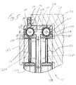
- FIG. 2 is a cross-sectional view of the bearing for a hub mounted vibration system shown in FIG. 1
- FIG. 3 is a cross-sectional view of a portion of the bearing for a hub mounted vibration system shown in FIG. 1 .
- FIG. 4 is a side view of a ball and slug separator for use with the bearing for a hub mounted vibration system shown in FIG. 1 .
- FIG. 5 is a cross sectional view of the bearing for a hub mounted vibration system of FIG. 1 shown with balancing magnets mounted therein and mounted on a hub mounted vibration system.
- FIG. 6 is an enlarged schematic view of a portion of the bearing of FIG. 1 .
- a light weight bearing 100 for use in airborne vibration suppression systems, for example, a hub-mounted vibration suppression system ("HMVSS") in accordance with the present invention is shown.
- the bearing 100 includes an outer ring 140.
- a first inner ring 120 is disposed in the outer ring 140 and a second inner ring 130 is disposed in the outer ring 140.
- the first inner ring 120 and the second inner ring 130 are disposed in the outer ring 140 in a side-by-side configuration.
- the first inner ring 120 is laterally displaced from the second inner ring 130 by a distance D 1 .
- the first inner ring 120, the second inner ring 130, and the outer ring 140 are each generally annular and share a common central axis A.
- the first inner ring 120 has an annular configuration and defines a central aperture 122.
- An inner surface 124 of the first inner ring 120 generally defines a perimeter of the central aperture 122.
- the inner ring 120 has an I-beam cross section defined by a mounting web, for example a mount 126, extending between two flanges 120A and 120B.
- the mount 126 is configured to receive a balancing magnet assembly 193, for example one or more balancing magnets (as shown in FIG. 5 ).
- the mount 126 has a plurality of holes 126H formed therein for weight reduction purposes.
- the I-beam cross section also is of benefit for weight reduction purposes.
- the second inner ring 130 is configured in the same manner as the first inner ring 120, although, it should be understood that the present invention is not limited in this regard and different configurations are possible.
- the second inner ring 130 has an annular configuration and defines a central aperture 132.
- An inner surface 134 of the second inner ring 130 generally defines a perimeter of the central aperture 132.
- the inner ring 130 has an I-beam cross section defined by a mounting web, for example a mount 136, extending between two flanges 130A and 130B.
- the mount 136 is configured to receive at least a portion of the HMVSS 192 (as shown in FIG. 5 ) to facilitate rotation of a rotor (not shown).
- the HMVSS is secured with fasteners 194 (only one shown) to an exterior annular flange 191 extending radially outward from the outer ring 140
- the second inner ring 130 has an outer surface 138 that defines a second inner race 139.
- the second inner ring 130 is disposed in the outer ring 140 opposite the second outer race 148.
- the mount 136 has a plurality of holes 136H formed therein for weight reduction purposes.
- the outer ring 140 has an annular configuration and defines a central aperture 142 for receiving the first inner ring 120 and the second inner ring 130.
- the outer ring 140 has an inner surface 144.
- the inner surface 144 defines a first outer race 146 and a second outer race 148.
- the first inner ring 120 has an outer surface 128 that defines a first inner race 129.
- the first inner ring 120 is disposed in the outer ring 140 opposite the first outer race 146.
- the first inner ring 120 is disposed in the outer ring 140 opposite the second outer race 146.
- the second inner ring 130 is disposed in the outer ring 140 opposite the second outer race 148.
- a first plurality of rolling elements 150 for example ball bearings is disposed between in a first cavity defined between the first inner race 129 and the first outer race 146.
- Each of the plurality of first rolling elements 150 has a first radius of curvature R B and a first circumference.
- a second plurality of rolling elements 160 for example ball bearings is disposed in a second cavity defined between the second inner race 139 and the second outer race 148.
- Each of the plurality of second rolling elements 160 has a second radius of curvature R B and a second circumference.
- Each of the plurality of first rolling elements 150 has a first radius of curvature R B and a first circumference.
- the first inner ring 120 is rotatable relative to the outer ring 140 about the central axis A.
- the first plurality of rolling elements 150 rollingly engages the first inner race 139 and the first outer race 146.
- the second inner ring 130 is rotatable relative to the outer ring 140 about the central axis A.
- the second plurality of rolling elements 160 rollingly engages the second inner race 139 and the second outer race 146.
- the first inner ring 120 is rotatable relative to the second inner ring 130 about central axis A.
- the first plurality of rolling elements 150 and the second plurality of rolling elements 160 includes a plurality of generally spherical balls.
- One slug separator 170 is disposed between and separates each adjacent pair of the first rolling elements 150.
- One second slug separator 180 is disposed between and separates each adjacent pair of the second rolling elements 160.
- the first plurality of slug separators 170 is disposed between the first inner race 129 and the first outer race 146.
- the second plurality of slug separators 180 is disposed between the second inner race 149 and the second outer race 148.
- the slug separators 170, 180 and rolling elements 150, 160 are arranged so that one slug separator 170, 180 is disposed between and slidingly engage each rolling element 150, 160, respectively, thereby separating adjacent rolling elements 150, 160 from one another.
- Each of the rolling elements 150, 160 has a radius R B .
- Each of the rolling elements 150, 160 has a circumference defined by two times the radius R B times ⁇ (i.e., ⁇ equals about 3.1428). In one embodiment the rolling elements 150 have a different radius R B than the rolling elements 160.
- the slug separators 170 extend between a first end 171 and a second end 172.
- the slug separator 170 defines a bore 173 therethrough between a first opening 174 and a second opening 175.
- a slug length is defined as the distance between the first end 171 and the second end 172.
- the slug separator 170 is generally annular about an axis B as shown in FIG. 4 , wherein axis B extends between the first opening 174 and the second opening 175.
- the slug separator 170 has an outer diameter and an inner diameter. The difference between the outer diameter and the inner diameter correspondences to twice the wall thickness T of the slug separator 170.
- the slug separators 180 are configured similar to the slug separators 170. While the slug separator 170 is shown as having a flat face, i.e., tubular, the present invention is not limited in this regard. For example, the face of the slug separator may be parabolic, or some other shape, to enhance the interface with the adjacent rolling element 150, 160.
- the slug separators 170, 180 are sized to space adjacent pairs of the rolling elements 150, 160 apart from one another by a predetermined distance. As shown in FIG. 1 , each of the rolling elements 150, 160 are spaced apart from one another by the slug separators 170, 180 an angle ⁇ . In one embodiment the angle ⁇ is 15 degrees plus or minus one degree. While the adjacent pairs of the rolling elements 150, 160 are described as being spaced apart from one another by a the angle ⁇ of 15 degrees, the present invention is not limited in this regard as the angle ⁇ may be less than or greater than 15 degrees, including but not limited to 5, 10, 11, 12, 13, 14, 16, 17, 18, 19 20, 21, 22, 23, 24 or 25 degrees.
- the slug separators 170, 180 are made from flexible inert plastics.
- the slug separators are cut from stocks of tubing or hosing.
- the slug separators 170 are formed from a synthetic polymeric material such as bearing grade PEEK (poly ether ether ketone) and/or other material e.g., PTFE (polytetrafluoroethylene), polyimide, etc.
- PEEK poly ether ether ketone
- PTFE polytetrafluoroethylene
- polyimide polyimide
- slug separators 170, 180 By using individual slug separators 170, 180 inserted between adjacent rolling elements 150, 160, additional space is provided, as compared to a bearing using a ball separator cage to space the balls. As a result of the additional space provided through use of the slug separators 170, 180, it is possible to use rolling members having a greater diameter as opposed to a similar sized bearing in which a separator cage is employed. For example, as shown in FIG. 6 the first and second inner races 129, 139 and the first and second outer races 146, 148 have a width W of .512 inch. Thus, rolling elements 150, 160 having a diameter of 0.3125 to 0.5 inch are used.
- Increasing the size of the rolling elements increases the load capacity and life of the bearing 100 by increasing the contact surface between the rolling elements 150, 160 as described further herein with reference to FIG. 6 . It has been shown that bearing life/longevity is a cubical function of its load capacity. As a result, increasing the diameter of the rolling elements 150, 160 to 0.3125 to 0.5, for example, increases the life of the bearing 100, compared to other bearings using small rolling elements.
- the slug separators 170, 180 inserted between the rolling elements 150, 160 additional space is provided that would normally be filled by the separator cage. Therefore, using tubular slugs, rolling elements 150, 160 having a diameter of up to about 0.5 inches are used.
- the rolling element 150, 160 size increase from 1/4" to 1 ⁇ 2" increases the load capacity of the bearing by 2.6 times that of a caged design.
- the diameter of the spherical rolling elements 150 used in the first inner and outer races 129, 146 and the diameter of the rolling elements 160 used in the second inner and outer race 139, 148 may be the same or may be different.
- the length and diameter of the slug separators 170 used in the first inner and outer races 129, 146 and the slug separators 180 used in the second inner and outer races 139, 148 may be the same or may be different.
- first and second inner races 129, 139 and the first and second outer races 146, 148 are described has having the width W of .512 inch and rolling elements 150, 160 having the diameter of 0.3125 to 0.5 inch, the present invention is not limited in this regard as races and rolling elements of any size and configuration may be employed, including but not limited to races and rolling elements as described herein with reference to FIG. 6 .
- the outer ring 140 defines the first outer race 146 and a second outer race 148.
- the first outer race 146 defines a first arcuate surface 146C extending a first length L OUT1 from point E to point F.
- the second outer race 148 defines second arcuate surface 148C extending a second length L OUT2 from point E to point F.
- the first inner ring 120 is disposed in the outer ring 140 opposite the first outer race 146 (as shown in FIG. 3 ).
- the first inner ring 120 defines the first inner race 129.
- the first inner race 129 defines a third arcuate surface 129C extending a third length L IN3 from point G to point H.
- the second inner ring 130 is disposed in the outer ring 140 (as shown in FIG. 3 ) opposite the second outer race 148.
- the second inner ring 130 defines a second inner race 139.
- the second inner race 139 defines a fourth arcuate surface 148C extending a fourth length L IN4 from point G to point H.
- the first arcuate surface 146C and the third arcuate surface 129C define a thin line of contact with each of the rolling elements 150.
- the second arcuate surface 148C and the fourth arcuate surface 139C define a thin line of contact with each of the rolling elements 160.
- first circumference of at least one of the plurality of first rolling 150 elements engages the first arcuate surface 146C and thirty percent of the first circumference of at least one of the plurality of first rolling elements 150 engages the third arcuate surface 129C.
- thirty percent of the second circumference of at least one of the plurality of second rolling elements 160 engages the second arcuate surface 148C and thirty percent of the second circumference of at least one of the plurality of second rolling elements 160 engages the fourth arcuate surface 139C.
- forty percent of the first circumference of at least one of the plurality of first rolling 150 elements engages the first arcuate surface 146C and forty percent of the first circumference of at least one of the plurality of first rolling elements 150 engages the third arcuate surface 129C. In one embodiment, forty percent of the second circumference of at least one of the plurality of second rolling elements 160 engages the second arcuate surface 148C and forty percent of the second circumference of at least one of the plurality of second rolling elements 160 engages the fourth arcuate surface 139C.
- the present invention is not limited in this regard as greater percentages (e.g., 45, 46, 47, 48, and 49 percent) of the circumference of the rolling elements 150, 160 can engage one or more of the first arcuate surface 146C, the second arcuate surface 148C, the third arcuate surface 129C and the fourth arcuate surface 148C.
- the first arcuate surface 146C of the first outer race 146 defines a first radius of curvature R OUT and the second arcuate surface 148C of the second outer race 148 defines second radius of curvature R OUT .
- the first inner ring 120 is disposed in the outer ring 140 opposite the first outer race 146.
- the third arcuate surface 129C of the first inner ring 120 defines a first inner race 129 which has a third radius of curvature R IN .
- the second inner ring 130 defines a second inner race 139 which has a fourth radius of curvature R IN .
- the first radius of curvature R OUT , second radius of curvature R OUT , third radius of curvature R IN and fourth radius of curvature R IN are substantially equal to one another.
- the first radius of curvature R OUT , second radius of curvature R OUT , third radius of curvature R IN and fourth radius of curvature R IN have different magnitudes.
- the first radius of curvature R OUT , second radius of curvature R OUT , third radius of curvature R IN and fourth radius of curvature R IN extend the full width W, as shown in FIG. 6 .
- the bearing 100 has a first aspect ratio defined by the radius R B of one of the rolling elements 150 divided by either of the first radius of curvature R OUT of the first outer race 146 or and the third radius of curvature R IN of the a first inner race 129.
- the bearing 100 has a second aspect ratio defined by radius R B of one of the rolling elements 160 divided by either of the one of the second radius of curvature R OUT of the second outer race 148 or the fourth radius of curvature R IN of the second inner race 139.
- the first aspect ratio and/or the second aspect ratio is at least 0.6. In one embodiment, the first aspect ratio and/or the second aspect ratio is at least 0.7. In one embodiment, the first aspect ratio and/or the second aspect ratio is at least 0.8. In one embodiment, the first aspect ratio and/or the second aspect ratio is at least 0.9.
Landscapes
- Engineering & Computer Science (AREA)
- General Engineering & Computer Science (AREA)
- Mechanical Engineering (AREA)
- Rolling Contact Bearings (AREA)
Applications Claiming Priority (1)
| Application Number | Priority Date | Filing Date | Title |
|---|---|---|---|
| US201261639261P | 2012-04-27 | 2012-04-27 |
Publications (2)
| Publication Number | Publication Date |
|---|---|
| EP2657555A2 true EP2657555A2 (de) | 2013-10-30 |
| EP2657555A3 EP2657555A3 (de) | 2015-03-04 |
Family
ID=48446045
Family Applications (1)
| Application Number | Title | Priority Date | Filing Date |
|---|---|---|---|
| EP13165655.5A Withdrawn EP2657555A3 (de) | 2012-04-27 | 2013-04-26 | Leichte Hochleistungskugellager zur Vibrationsunterdrückung in der Luft |
Country Status (1)
| Country | Link |
|---|---|
| EP (1) | EP2657555A3 (de) |
Cited By (3)
| Publication number | Priority date | Publication date | Assignee | Title |
|---|---|---|---|---|
| CN108397477A (zh) * | 2018-04-24 | 2018-08-14 | 瓦房店爱国轴承研究院有限公司 | 三弧面滚道深沟球轴承 |
| CN112664556A (zh) * | 2020-12-23 | 2021-04-16 | 南通高盛机械制造有限公司 | 一种开口轴承 |
| US11166785B2 (en) * | 2015-09-22 | 2021-11-09 | Gebruder Reinfurt Gmbh & Co. Kg | Ball bearing construction with tilt compensation |
Citations (1)
| Publication number | Priority date | Publication date | Assignee | Title |
|---|---|---|---|---|
| US20110027081A1 (en) | 2004-08-30 | 2011-02-03 | Jolly Mark R | Helicopter hub mounted vibration control and circular force generation systems for canceling vibrations |
Family Cites Families (4)
| Publication number | Priority date | Publication date | Assignee | Title |
|---|---|---|---|---|
| IT210935Z2 (it) * | 1986-06-13 | 1989-01-11 | Bonfiglioli Trasmital Spa | Cuscinetto integrato per organi riduttori |
| US8215845B2 (en) * | 2006-03-13 | 2012-07-10 | Roller Bearing Company Of America, Inc. | Tandem stack angular contact bearing for rotary wing aircraft |
| US20090060706A1 (en) * | 2007-09-05 | 2009-03-05 | Roller Bearing Company Of America, Inc | Ball bearing and pump for cryogenic use |
| WO2012021202A2 (en) * | 2010-05-26 | 2012-02-16 | Lord Corporation | Real time active helicopter vibration control and rotor track and balance systems |
-
2013
- 2013-04-26 EP EP13165655.5A patent/EP2657555A3/de not_active Withdrawn
Patent Citations (1)
| Publication number | Priority date | Publication date | Assignee | Title |
|---|---|---|---|---|
| US20110027081A1 (en) | 2004-08-30 | 2011-02-03 | Jolly Mark R | Helicopter hub mounted vibration control and circular force generation systems for canceling vibrations |
Cited By (4)
| Publication number | Priority date | Publication date | Assignee | Title |
|---|---|---|---|---|
| US11166785B2 (en) * | 2015-09-22 | 2021-11-09 | Gebruder Reinfurt Gmbh & Co. Kg | Ball bearing construction with tilt compensation |
| CN108397477A (zh) * | 2018-04-24 | 2018-08-14 | 瓦房店爱国轴承研究院有限公司 | 三弧面滚道深沟球轴承 |
| CN108397477B (zh) * | 2018-04-24 | 2023-11-14 | 瓦房店爱国轴承研究院有限公司 | 三弧面滚道深沟球轴承 |
| CN112664556A (zh) * | 2020-12-23 | 2021-04-16 | 南通高盛机械制造有限公司 | 一种开口轴承 |
Also Published As
| Publication number | Publication date |
|---|---|
| EP2657555A3 (de) | 2015-03-04 |
Similar Documents
| Publication | Publication Date | Title |
|---|---|---|
| US8021053B2 (en) | Rotary wing aircraft ball bearing | |
| US8425122B2 (en) | Angular contact rolling-element bearing, especially double row ball roller bearing in tandem arrangement | |
| US8167501B2 (en) | Separator for bearing assemblies with cyclic loads | |
| EP1835190A2 (de) | Tandemschrägkugellager für einen Drehflügler | |
| DK2715162T3 (en) | Large roller bearing | |
| US9422976B2 (en) | Axial-radial rolling contact bearing, in particular for supporting rotor blades on a wind turbine | |
| CN1860306A (zh) | 自动调心滚动轴承和用于自动调心滚动轴承的保持架 | |
| US20160090966A1 (en) | Wind turbine rotor shaft arrangement | |
| EP2657555A2 (de) | Leichte Hochleistungskugellager zur Vibrationsunterdrückung in der Luft | |
| US20160010688A1 (en) | Low friction multi stage thrust bearing | |
| EP2600005B1 (de) | Vakuumpumpe mit einem käfiglosen Wälzlager | |
| US8215845B2 (en) | Tandem stack angular contact bearing for rotary wing aircraft | |
| US9273728B2 (en) | Rolling bearing having rings with stepped surfaces opposite to the raceways | |
| US20130294716A1 (en) | High-capacity light-weight ball bearing for airborne vibration suppression applications | |
| US20210102576A1 (en) | Self-aligning roller bearing | |
| CN212202853U (zh) | 双列角接触球轴承 | |
| US8176674B2 (en) | Roller assembly for fishing rod roller guide | |
| US9657778B1 (en) | Convertible cage for ball bearing and associated bearing | |
| US20160017918A1 (en) | Ball separator for ball bearing assembly | |
| US11415173B2 (en) | Elastomeric bearing having reduced-weight end cap | |
| US10871191B2 (en) | Rolling bearing and bearing structure including same | |
| US4493514A (en) | Mechanism for proportionately loading dual thrust bearing assemblies against axial thrust loads | |
| US11913496B2 (en) | Elastomeric bearing having carbon-fiber reinforced laminae | |
| WO2021188328A1 (en) | Roller bearing with axially-fixed, rotatable rib flange | |
| US9909620B2 (en) | Radial roller cage with centerline guidance |
Legal Events
| Date | Code | Title | Description |
|---|---|---|---|
| PUAI | Public reference made under article 153(3) epc to a published international application that has entered the european phase |
Free format text: ORIGINAL CODE: 0009012 |
|
| 17P | Request for examination filed |
Effective date: 20130426 |
|
| AK | Designated contracting states |
Kind code of ref document: A2 Designated state(s): AL AT BE BG CH CY CZ DE DK EE ES FI FR GB GR HR HU IE IS IT LI LT LU LV MC MK MT NL NO PL PT RO RS SE SI SK SM TR |
|
| AX | Request for extension of the european patent |
Extension state: BA ME |
|
| PUAL | Search report despatched |
Free format text: ORIGINAL CODE: 0009013 |
|
| RIC1 | Information provided on ipc code assigned before grant |
Ipc: F16C 19/28 20060101ALI20150122BHEP Ipc: F16C 19/20 20060101ALI20150122BHEP Ipc: F16C 33/37 20060101ALI20150122BHEP Ipc: F16C 33/372 20060101AFI20150122BHEP Ipc: F16C 19/08 20060101ALI20150122BHEP Ipc: F16C 19/52 20060101ALI20150122BHEP Ipc: F16C 19/40 20060101ALN20150122BHEP Ipc: F16C 33/60 20060101ALI20150122BHEP Ipc: B64C 27/00 20060101ALN20150122BHEP Ipc: F16C 33/58 20060101ALI20150122BHEP |
|
| AK | Designated contracting states |
Kind code of ref document: A3 Designated state(s): AL AT BE BG CH CY CZ DE DK EE ES FI FR GB GR HR HU IE IS IT LI LT LU LV MC MK MT NL NO PL PT RO RS SE SI SK SM TR |
|
| AX | Request for extension of the european patent |
Extension state: BA ME |
|
| RBV | Designated contracting states (corrected) |
Designated state(s): AL AT BE BG CH CY CZ DE DK EE ES FI FR GB GR HR HU IE IS IT LI LT LU LV MC MK MT NL NO PL PT RO RS SE SI SK SM TR |
|
| STAA | Information on the status of an ep patent application or granted ep patent |
Free format text: STATUS: THE APPLICATION IS DEEMED TO BE WITHDRAWN |
|
| 18D | Application deemed to be withdrawn |
Effective date: 20181101 |