EP2657577A1 - Dispositif de commande de véhicule et véhicule automatique à deux roues équipé de ce dispositif - Google Patents
Dispositif de commande de véhicule et véhicule automatique à deux roues équipé de ce dispositif Download PDFInfo
- Publication number
- EP2657577A1 EP2657577A1 EP11851162.5A EP11851162A EP2657577A1 EP 2657577 A1 EP2657577 A1 EP 2657577A1 EP 11851162 A EP11851162 A EP 11851162A EP 2657577 A1 EP2657577 A1 EP 2657577A1
- Authority
- EP
- European Patent Office
- Prior art keywords
- rotation speed
- gear
- control
- control unit
- engine
- Prior art date
- Legal status (The legal status is an assumption and is not a legal conclusion. Google has not performed a legal analysis and makes no representation as to the accuracy of the status listed.)
- Granted
Links
Images













Classifications
-
- B—PERFORMING OPERATIONS; TRANSPORTING
- B60—VEHICLES IN GENERAL
- B60W—CONJOINT CONTROL OF VEHICLE SUB-UNITS OF DIFFERENT TYPE OR DIFFERENT FUNCTION; CONTROL SYSTEMS SPECIALLY ADAPTED FOR HYBRID VEHICLES; ROAD VEHICLE DRIVE CONTROL SYSTEMS FOR PURPOSES NOT RELATED TO THE CONTROL OF A PARTICULAR SUB-UNIT
- B60W30/00—Purposes of road vehicle drive control systems not related to the control of a particular sub-unit, e.g. of systems using conjoint control of vehicle sub-units
- B60W30/18—Propelling the vehicle
- B60W30/19—Improvement of gear change, e.g. by synchronisation or smoothing gear shift
-
- B—PERFORMING OPERATIONS; TRANSPORTING
- B60—VEHICLES IN GENERAL
- B60W—CONJOINT CONTROL OF VEHICLE SUB-UNITS OF DIFFERENT TYPE OR DIFFERENT FUNCTION; CONTROL SYSTEMS SPECIALLY ADAPTED FOR HYBRID VEHICLES; ROAD VEHICLE DRIVE CONTROL SYSTEMS FOR PURPOSES NOT RELATED TO THE CONTROL OF A PARTICULAR SUB-UNIT
- B60W10/00—Conjoint control of vehicle sub-units of different type or different function
- B60W10/02—Conjoint control of vehicle sub-units of different type or different function including control of driveline clutches
-
- B—PERFORMING OPERATIONS; TRANSPORTING
- B60—VEHICLES IN GENERAL
- B60W—CONJOINT CONTROL OF VEHICLE SUB-UNITS OF DIFFERENT TYPE OR DIFFERENT FUNCTION; CONTROL SYSTEMS SPECIALLY ADAPTED FOR HYBRID VEHICLES; ROAD VEHICLE DRIVE CONTROL SYSTEMS FOR PURPOSES NOT RELATED TO THE CONTROL OF A PARTICULAR SUB-UNIT
- B60W10/00—Conjoint control of vehicle sub-units of different type or different function
- B60W10/04—Conjoint control of vehicle sub-units of different type or different function including control of propulsion units
- B60W10/06—Conjoint control of vehicle sub-units of different type or different function including control of propulsion units including control of combustion engines
-
- B—PERFORMING OPERATIONS; TRANSPORTING
- B60—VEHICLES IN GENERAL
- B60W—CONJOINT CONTROL OF VEHICLE SUB-UNITS OF DIFFERENT TYPE OR DIFFERENT FUNCTION; CONTROL SYSTEMS SPECIALLY ADAPTED FOR HYBRID VEHICLES; ROAD VEHICLE DRIVE CONTROL SYSTEMS FOR PURPOSES NOT RELATED TO THE CONTROL OF A PARTICULAR SUB-UNIT
- B60W10/00—Conjoint control of vehicle sub-units of different type or different function
- B60W10/10—Conjoint control of vehicle sub-units of different type or different function including control of change-speed gearings
- B60W10/11—Stepped gearings
- B60W10/113—Stepped gearings with two input flow paths, e.g. double clutch transmission selection of one of the torque flow paths by the corresponding input clutch
-
- F—MECHANICAL ENGINEERING; LIGHTING; HEATING; WEAPONS; BLASTING
- F16—ENGINEERING ELEMENTS AND UNITS; GENERAL MEASURES FOR PRODUCING AND MAINTAINING EFFECTIVE FUNCTIONING OF MACHINES OR INSTALLATIONS; THERMAL INSULATION IN GENERAL
- F16H—GEARING
- F16H61/00—Control functions within control units of change-speed- or reversing-gearings for conveying rotary motion ; Control of exclusively fluid gearing, friction gearing, gearings with endless flexible members or other particular types of gearing
- F16H61/04—Smoothing ratio shift
- F16H61/0437—Smoothing ratio shift by using electrical signals
-
- F—MECHANICAL ENGINEERING; LIGHTING; HEATING; WEAPONS; BLASTING
- F16—ENGINEERING ELEMENTS AND UNITS; GENERAL MEASURES FOR PRODUCING AND MAINTAINING EFFECTIVE FUNCTIONING OF MACHINES OR INSTALLATIONS; THERMAL INSULATION IN GENERAL
- F16H—GEARING
- F16H61/00—Control functions within control units of change-speed- or reversing-gearings for conveying rotary motion ; Control of exclusively fluid gearing, friction gearing, gearings with endless flexible members or other particular types of gearing
- F16H61/68—Control functions within control units of change-speed- or reversing-gearings for conveying rotary motion ; Control of exclusively fluid gearing, friction gearing, gearings with endless flexible members or other particular types of gearing specially adapted for stepped gearings
- F16H61/684—Control functions within control units of change-speed- or reversing-gearings for conveying rotary motion ; Control of exclusively fluid gearing, friction gearing, gearings with endless flexible members or other particular types of gearing specially adapted for stepped gearings without interruption of drive
- F16H61/688—Control functions within control units of change-speed- or reversing-gearings for conveying rotary motion ; Control of exclusively fluid gearing, friction gearing, gearings with endless flexible members or other particular types of gearing specially adapted for stepped gearings without interruption of drive with two inputs, e.g. selection of one of two torque-flow paths by clutches
-
- F—MECHANICAL ENGINEERING; LIGHTING; HEATING; WEAPONS; BLASTING
- F16—ENGINEERING ELEMENTS AND UNITS; GENERAL MEASURES FOR PRODUCING AND MAINTAINING EFFECTIVE FUNCTIONING OF MACHINES OR INSTALLATIONS; THERMAL INSULATION IN GENERAL
- F16H—GEARING
- F16H63/00—Control outputs from the control unit to change-speed- or reversing-gearings for conveying rotary motion or to other devices than the final output mechanism
- F16H63/40—Control outputs from the control unit to change-speed- or reversing-gearings for conveying rotary motion or to other devices than the final output mechanism comprising signals other than signals for actuating the final output mechanisms
- F16H63/50—Signals to an engine or motor
- F16H63/502—Signals to an engine or motor for smoothing gear shifts
-
- B—PERFORMING OPERATIONS; TRANSPORTING
- B60—VEHICLES IN GENERAL
- B60W—CONJOINT CONTROL OF VEHICLE SUB-UNITS OF DIFFERENT TYPE OR DIFFERENT FUNCTION; CONTROL SYSTEMS SPECIALLY ADAPTED FOR HYBRID VEHICLES; ROAD VEHICLE DRIVE CONTROL SYSTEMS FOR PURPOSES NOT RELATED TO THE CONTROL OF A PARTICULAR SUB-UNIT
- B60W2556/00—Input parameters relating to data
-
- B—PERFORMING OPERATIONS; TRANSPORTING
- B60—VEHICLES IN GENERAL
- B60W—CONJOINT CONTROL OF VEHICLE SUB-UNITS OF DIFFERENT TYPE OR DIFFERENT FUNCTION; CONTROL SYSTEMS SPECIALLY ADAPTED FOR HYBRID VEHICLES; ROAD VEHICLE DRIVE CONTROL SYSTEMS FOR PURPOSES NOT RELATED TO THE CONTROL OF A PARTICULAR SUB-UNIT
- B60W2710/00—Output or target parameters relating to a particular sub-units
- B60W2710/06—Combustion engines, Gas turbines
- B60W2710/0644—Engine speed
-
- B—PERFORMING OPERATIONS; TRANSPORTING
- B60—VEHICLES IN GENERAL
- B60Y—INDEXING SCHEME RELATING TO ASPECTS CROSS-CUTTING VEHICLE TECHNOLOGY
- B60Y2200/00—Type of vehicle
- B60Y2200/10—Road Vehicles
- B60Y2200/12—Motorcycles, Trikes; Quads; Scooters
-
- B—PERFORMING OPERATIONS; TRANSPORTING
- B60—VEHICLES IN GENERAL
- B60Y—INDEXING SCHEME RELATING TO ASPECTS CROSS-CUTTING VEHICLE TECHNOLOGY
- B60Y2400/00—Special features of vehicle units
- B60Y2400/42—Clutches or brakes
- B60Y2400/421—Dog type clutches or brakes
-
- F—MECHANICAL ENGINEERING; LIGHTING; HEATING; WEAPONS; BLASTING
- F16—ENGINEERING ELEMENTS AND UNITS; GENERAL MEASURES FOR PRODUCING AND MAINTAINING EFFECTIVE FUNCTIONING OF MACHINES OR INSTALLATIONS; THERMAL INSULATION IN GENERAL
- F16H—GEARING
- F16H2306/00—Shifting
- F16H2306/18—Preparing coupling or engaging of future gear
-
- F—MECHANICAL ENGINEERING; LIGHTING; HEATING; WEAPONS; BLASTING
- F16—ENGINEERING ELEMENTS AND UNITS; GENERAL MEASURES FOR PRODUCING AND MAINTAINING EFFECTIVE FUNCTIONING OF MACHINES OR INSTALLATIONS; THERMAL INSULATION IN GENERAL
- F16H—GEARING
- F16H2306/00—Shifting
- F16H2306/40—Shifting activities
- F16H2306/54—Synchronising engine speed to transmission input speed
-
- F—MECHANICAL ENGINEERING; LIGHTING; HEATING; WEAPONS; BLASTING
- F16—ENGINEERING ELEMENTS AND UNITS; GENERAL MEASURES FOR PRODUCING AND MAINTAINING EFFECTIVE FUNCTIONING OF MACHINES OR INSTALLATIONS; THERMAL INSULATION IN GENERAL
- F16H—GEARING
- F16H63/00—Control outputs from the control unit to change-speed- or reversing-gearings for conveying rotary motion or to other devices than the final output mechanism
- F16H63/02—Final output mechanisms therefor; Actuating means for the final output mechanisms
- F16H63/08—Multiple final output mechanisms being moved by a single common final actuating mechanism
- F16H63/16—Multiple final output mechanisms being moved by a single common final actuating mechanism the final output mechanisms being successively actuated by progressive movement of the final actuating mechanism
- F16H63/18—Multiple final output mechanisms being moved by a single common final actuating mechanism the final output mechanisms being successively actuated by progressive movement of the final actuating mechanism the final actuating mechanism comprising cams
Definitions
- the present invention relates to a control device for a vehicle and a motorcycle having two paths as power transmission paths that extend from an engine to an output shaft of a transmission, and clutches arranged in the paths respectively.
- Patent Literature 1 discloses a vehicle of a dual clutch type.
- two paths are disposed as power transmission paths that extend from the engine to the output shaft of the transmission.
- a clutch and a transmission mechanism are disposed in each of those two paths. That is, one clutch is connected with the transmission mechanism having gears for even gear levels, and the other clutch is connected with the transmission mechanism having gears for odd gear levels.
- Those two transmission mechanism have a common output shaft.
- the transmission provided in the vehicle disclosed in Patent Literature 1 is a transmission of a so-called dog clutch type.
- the dog clutch (dog teeth or dog holes) is formed in each of the gears, and a gear pair having the two gears can be engaged with each other by the dog clutches.
- a gear pair In a normal running, a gear pair is engaged with each other in only one transmission mechanism, and all of the gear pairs are put in a neutral state (disengaged state) in the other transmission mechanism.
- a path for transmitting a power is switched from one to the other. That is, the gear pair of one transmission mechanism in the engaged state is changed to the neutral state, and the gear pair of the other transmission mechanism is changed to the engaged state. Also, the clutch connected with the other transmission mechanism (clutch that starts the power transmission by shifting) is transitioned from the disengaged state to the engaged state.
- a shifting shock may be caused.
- the engine rotation speed in some cases is increased or decreased toward an engine rotation speed (hereinafter, referred to as "target rotation speed") obtained by a shifting before the driving member and the driven member of the clutch are engaged with each other, where the target rotation speed is determined from a vehicle velocity during shifting and a gear ratio of the next gear level.
- the present invention has been made in view of the above problem, and an object of the present invention is to provide a control device for a vehicle and a motorcycle with the control device, which can smoothly engage a gear pair with each other while suppressing a shifting shock.
- a control device is mounted on a vehicle which includes, in a power transmission path for transmitting a power of an engine, two clutches receiving the power from the engine, and two transmission mechanisms arranged downstream of the respective clutches and having a common output shaft.
- each of the two transmission mechanisms includes a first gear which rotates together with a driven member of the clutch, and a second gear which rotates together with the output shaft, movable relative to the first gear, and engageable with the first gear by a dog clutch.
- the control device switches the path for transmitting the power from one of the clutches and the transmission mechanism to the other clutch and transmission mechanism according to the shift command.
- a first control device which is the control device includes a gear control unit, a rotation speed control unit, and a clutch control unit.
- the gear control unit brings the first gear and the second gear close to each other in the transmission mechanism that starts the power transmission according to the shift command.
- the rotation speed control unit sets, as a target rotation speed, an engine rotation speed corresponding to a vehicle velocity and a speed reduction ratio realized by engagement of the first gear and the second gear brought close to each other by the gear control unit and controls the engine rotation speed toward the target rotation speed. Also, the rotation speed control unit prevents the engine rotation speed from arriving at the target rotation speed until the first gear and the second gear are engaged with each other.
- the clutch control unit brings a clutch that starts the power transmission according to the shift command close to an engaged state, and the other clutch close to a disengaged state, when the engine rotation speed arrives at the target rotation speed.
- the clutch control unit brings the clutch that starts the power transmission according to the shift command close to the engaged state when the engine rotation speed arrives at the target rotation speed. For that reason, the shifting shock can be suppressed. Also, the rotation speed control unit prevents the engine rotation speed from arriving at the target rotation speed until the first gear and the second gear are engaged with each other. For that reason, the first gear and the second gear can be smoothly engaged with each other.
- a second control device is also a control device mounted on the vehicle.
- the second control device includes a gear control unit, a rotation speed control unit, and a clutch control unit.
- the gear control unit brings two gears close to each other in the transmission mechanism that starts the power transmission according to the shift command.
- the rotation speed control unit sets, as a target rotation speed, an engine rotation speed corresponding to the vehicle velocity and a speed reduction ratio realized by engagement of the two gears brought close to each other by the gear control unit, and controls the engine rotation speed toward the target rotation speed.
- the rotation speed control unit changes the engine rotation speed to a rotation speed that exceeds the target rotation speed and then prevents the engine rotation speed from returning to the target rotation speed until the two gears are engaged with each other by the gear engagement unit.
- the clutch control unit brings the clutch that starts the power transmission according to the shift command close to an engaged state, and the other clutch close to a disengaged state, when the engine rotation speed arrives at the target rotation speed.
- the clutch control unit brings the clutch that starts the power transmission according to the shift command close to the engaged state when the engine rotation speed arrives (returns) at the target rotation speed. For that reason, the shifting shock can be suppressed. Also, the rotation speed control unit prevents the engine rotation speed from returning to the target rotation speed until the two gears are engaged with each other after changing the engine rotation speed up to a rotation speed exceeding the target rotation speed. For that reason, the first gear and the second gear can be smoothly engaged with each other.
- a third control device is also a control device mounted on the vehicle.
- the third control device includes a gear control unit, a collision determination unit, a rotation speed control unit, and a clutch control unit.
- the gear control unit brings the first gear and the second gear close to each other in the transmission mechanism that starts the power transmission according to the shift command.
- the collision determination unit determines whether dog clutches thereof collide with each other without engagement of the first gear and the second gear which are brought close to each other by the gear control unit, or not.
- the rotation speed control unit sets, as a target rotation speed, an engine rotation speed corresponding to a vehicle velocity and a speed reduction ratio realized by the engagement of the first gear and the second gear brought close to each other by the gear control unit.
- the target rotation speed controls the engine rotation speed toward the target rotation speed.
- the rotation speed control unit changes the engine rotation speed to move away from the target rotation speed.
- the clutch control unit brings the clutch that starts the power transmission according to the shift command close to the engaged state, and the other clutch close to the disengaged state, when the engine rotation speed arrives at the target rotation speed.
- the clutch control unit brings the clutch that starts the power transmission according to the shift command close to the engaged state when the engine rotation speed arrives at the target rotation speed. For that reason, the shifting shock can be suppressed. Also, when the dog clutches collide with each other between the first gear and the second gear, the rotation speed control unit changes the engine rotation speed to move away from the target rotation speed. For that reason, even if the dog clutches collide with each other, the first gear and the second gear can be engaged with each other with elimination of the collision in a short time.
- the motorcycle according to the present invention includes any one of the first control device, the second control device, and the third control device.
- FIG. 1 is a side view of a motorcycle 1 having a control device 10 according to an example of an embodiment of the present invention.
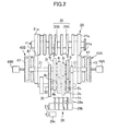
- FIG. 2 is a schematic diagram of a mechanism provided in a torque transmission path extending from an engine 20 to a rear wheel 3.
- FIG. 3 is a block diagram illustrating a configuration of the motorcycle 1.
- the motorcycle 1 includes a front wheel 2, the rear wheel 3, and an engine unit 11.
- the front wheel 2 is supported by lower ends of a front fork 4.
- An upper portion of the front fork 4 is coupled with a steering shaft 5 rotatably supported by a foremost part of a vehicle body frame (not shown) .
- a steering 6 is disposed above the steering shaft 5. The steering 6, the front fork 4, and the front wheel 2 can be rotated about the steering shaft 5 integrally from side to side.
- a seat 7 which a rider straddles and sits on is arranged in the rear of the steering 6.
- the rear wheel 3 is arranged in the rear of the engine unit 11.
- a torque output from a transmission 30 (refer to FIG. 2 ) is transmitted to the rear wheel 3 through a torque transmission member (not shown) such as a chain, a belt, or a drive shaft.
- the engine unit 11 includes the engine 20 and the transmission 30.
- the motorcycle 1 is a vehicle of a so-called dual clutch type, and a first clutch 40A and a second clutch 40B are installed on the engine unit 11.
- the engine 20 has a crankshaft 21 that rotates by driving of the engine 20
- a torque (rotation of the crankshaft 21) of the engine 20 is input to each of the first clutch 40A and the second clutch 40B.
- the first clutch 40A and the second clutch 40B each have a driving member 41 that is operated simultaneously with the rotation of the crankshaft 21.
- the crankshaft 21 has two primary gears 21a.
- the driving member 41 of the first clutch 40A and the driving member 41 of the second clutch 40B are each equipped with a primary gear 41a.
- the primary gears 41a are engaged with the corresponding primary gears 21a.
- the first clutch 40A and the second clutch 40B include driven members 42 that are interlocked with input shafts 31 of transmission mechanisms 30A and 30B which will be described later, respectively.
- the first clutch 40A and the second clutch 40B are each formed of, for example, a single-plate or multiplate friction clutch.
- Each driving member 41 and the corresponding driven member 42 are pushed against each other in an axial direction to transmit a torque therebetween.
- the driving member 41 is, for example, a friction disc
- the driven member 42 is, for example, a clutch disc.
- the transmission 30 includes the first transmission mechanism 30A and the second transmission mechanism 30B.
- the first transmission mechanism 30A and the second transmission mechanism 30B are disposed downstream of the first clutch 40A and the second clutch 40B, respectively. That is, the respective input shafts 31 are disposed in the first transmission mechanism 30A and the second transmission mechanism 308.
- the input shaft 31 of the first transmission mechanism 30A is coupled to the driven member 42 of the first clutch 40A, and the torque is input to the first transmission mechanism 30A through the first clutch 40A.
- the input shaft 31 of the second transmission mechanism 30B is coupled to the driven member 42 of the second clutch 40B, and the torque is input to the second transmission mechanism 30B through the second clutch 40B.
- the first transmission mechanisms 30A and 30B have a common output shaft 32.
- the motorcycle 1 has two paths as the torque transmission paths extending from the crankshaft 21 of the engine 20 to the output shaft 32 of the transmission 30.
- a first path is configured by the first transmission mechanism 30A and the first clutch 40A, and a second path is configured by the second transmission mechanism 30B and the second clutch 40B.
- the output shaft 32 of the transmission 30 is coupled to an axle shaft of the rear wheel 3 through the torque transmission member formed of a chain, a belt, or a shaft.
- the first transmission mechanism 30A and the second transmission mechanism 30B include a plurality of gears 1i to 6i and 1h to 6h.
- the gears 1i to 6i are disposed on the input shafts 31, and the gears 1h to 6h are disposed on the output shaft 32.
- the gear 1i and the gear 1h are engaged with each other, and a speed reduction ratio of those gears corresponds to a first gear level.
- the gears 2i to 6i are engaged with the gears 2h to 6h, respectively, and the respective reduction ratios of those gears correspond to second to sixth.
- the first transmission mechanism 30A is configured by the gears 1i, 3i, 5i, 1h, 3h, and 5h corresponding to odd gear levels
- the second transmission mechanism 30B is configured by the gears 2i, 4i, 6i, 2h, 4h, and 6h corresponding to even gear levels.
- the transmission mechanisms 30A and 30B are transmission mechanisms of a so-called selective slide type. Any one of the gear pair (for example, the gear 1i and the gear 1h) corresponding to each gear level is rotatable relative to a shaft on which the one gear is disposed. On the other hand, the other gear is splined to a shaft on which the other gear is disposed, and rotates together with that shaft. In this example, the gears 1h, 5i, 3h, 4h, 6i, and 2h are rotatable relative to the respective shafts on which those gears are disposed.
- the gears 1i, 5h, 3i, 4i, 6h, and 2i are meshed with the respective shafts on which those gears are disposed, and rotate together with those shafts. For that reason, in a neutral state (state in which none of gear levels is set), the gear pairs (5i, 5h) and (6, 6h) are interlocked with the output shaft 32, and the gear pairs (1i, 1h), (3i, 3h), (4i, 4h), and (2i, 2h) are interlock with the input shaft 31.
- the gears interlocked with the input shaft 31 and the gears interlocked with the output shaft 32 are arranged to be adjacent to each other in the axial direction, and also relatively movable in the axial direction (movable in an approaching direction and in a direction away from each other).
- the plurality of gears 1i to 6i and 1h to 6h include the gears having the dog clutch formed therein.
- the gears interlocked with the input shaft 31 and the gears interlocked with the output shaft 32 are engaged with each other by the dog clutch. With the engagement of those two gears, the rotation (torque) of the input shaft 31 of the first transmission mechanism 30A or the input shaft 31 of the second transmission mechanism 30B is transmitted to the output shaft 32.
- the gears 5h, 3i, 4i, and 6h are movable in the axial direction.
- the transmission 30 is equipped with a shift actuator 39 that moves the gears 5h, 3i, 4i, and 6h (hereinafter referred to as "movable gears") movable in the axial direction, in the axial direction.
- the shift actuator 39 includes a plurality of shift forks 39a caught by the movable gears, a shift cam 39b that moves the shift forks 39a in the axial direction by rotation, and an electric motor 39c that generates a power for rotating the shift cam 39b.
- the shift actuator 39 moves the movable gears under the control of the control device 10, and switches the gear level to another.
- the clutches 40A and 40B are equipped with clutch actuators 49A and 49B that move the clutches 40A and 40B under the control of the control device 10 (that is, the clutches 40A and 40B are brought into an engaged state or into a disengaged state).
- the clutch actuators 49A and 49B each include, for example, an electric motor. The power of each electric motor is transmitted to any one of the driving member 41 and the driven member 42 in each of the clutches 40A and 40B through a hydraulic pressure or a rod to push the driving member 41 and driven member 42 against each other in the axial direction.
- the engine 20 is equipped with a fuel injection device 22, a throttle actuator 23, and an ignition plug 24.
- the fuel injection device 22 supplies a fuel which is burned in a combustion chamber of the engine 20 to the engine 20.
- the throttle actuator 23 controls the opening degree of a throttle valve (not shown) for adjusting the amount of air flowing in an intake passage of the engine 20.
- the ignition plug 24 ignites a mixture gas of air and fuel pouring into the combustion chamber of the engine 20.
- the fuel injection amount of the fuel injection device 22, the ignition timing of the ignition plug 24, and the opening degree (hereinafter referred to as "throttle opening degree") of the throttle valve are controlled by the control device 10.
- the motorcycle 1 includes an engine rotation speed sensor 19a, a gear position sensor 19b, clutch sensors 19c, 19d, an output side rotation sensor 19e, a shift switch 19f, and an accelerator sensor 19g. Those sensors are connected to the control device 10.
- the engine rotation speed sensor 19a is configured by a rotation sensor that outputs a pulse signal of a frequency corresponding to an engine rotation speed.
- the control device 10 calculates the engine rotation speed (rotation speed of the crankshaft 21) on the basis of an output signal of the engine rotation speed sensor 19a.
- the gear position sensor 19b is configured by a potentiometer that outputs a voltage signal corresponding to a rotation angle of, for example, the shift cam 39b.
- the control device 10 detects positions of the movable gears 5h, 3i, 4i, and 6h, and the present gear level on the basis of an output signal of the gear position sensor 19b.
- the output side rotation sensor 19e is disposed on the axle shaft of the rear wheel 3, or the output shaft 32.
- the output side rotation sensor 19e is a rotation sensor that outputs a pulse signal of a frequency corresponding to, for example, the rotation speed of the rear wheel 3, or the rotation speed of the output shaft 32.
- the control device 10 calculates the vehicle velocity and the rotation speed of the output shaft 32 on the basis of the output signal of the output side rotation sensor 19e.
- the shift switch 19f is a switch operated by a rider, and inputs a shift command (a signal indicative of a shift-up command for shifting up the gear level, or a signal indicative of a shift-down command for shifting down the gear level) of the rider to the control device 10.
- the shift switch 19f is equipped with a shift-up switch and a shift-down switch.
- the accelerator sensor 19a outputs a signal corresponding to the amount of operation (rotation angle) of an accelerator grip (not shown) equipped in the steering 6.
- the accelerator sensor 19g is configured by, for example, a potentiometer.
- the control device 10 detects the amount of operation (accelerator operation amount) of the accelerator grip on the basis of the output signal of the accelerator sensor 19g.
- the clutch sensor 19c is a sensor for detecting a transmitted torque capacity (transmittable maximum torque in a present state (that is, present engagement degree) of the first clutch 40A) of the first clutch 40A.
- the clutch sensor 19d is a sensor for detecting a transmitted torque capacity (transmittable maximum torque in a present state (that is, present engagement degree) of the second clutch 40B) of the second clutch 40B.
- the transmitted torque capacity becomes maximum when the clutches 40A and 40B are in the engaged state, and the transmitted torque capacity becomes minimum (for example, 0 Nm) when the clutches 40A and 40B are in a disengaged state.
- the transmitted torque capacity corresponds to the positions (stroke quantities of the clutches) of the clutches 40A and 40B.
- the clutch sensors 19c and 19d are potentiometers that output signals (signals corresponding to the operation quantities of the clutch actuators 49A and 49B) corresponding to the positions of, for example, the clutches 40A and 40B.
- the control device 10 detects the transmitted torque capacities from the clutch positions detected on the basis of the output signals of the clutch sensors 19c and 19d. For example, the control device 10 calculates the transmitted torque capacities from the detected clutch positions with the use of a map or an arithmetic expression that associate the clutch positions with the transmitted torque capacities.
- the transmitted torque capacities correspond to the hydraulic pressures (hereinafter referred to as "clutch pressures") exerted on the clutches 40A and 40B.
- the clutch sensors 19c and 19d are hydraulic sensors that output signals corresponding to the clutch pressures.
- the control device 10 detects the transmitted torque capacities from the clutch pressures detected on the basis of the outputs of the clutch sensors 19c and 19d. For example, the control device 10 calculates the transmitted torque capacities according to the detected clutch pressures with the use of the map or the arithmetic expression that associates the clutch pressures with the transmitted torque capacities.
- the transmitted torque capacities correspond to forces (pushing force exerted between the driving member 41 and the driven member 42) exerted on the clutches 40A and 40B from the clutch actuators 49A and 49B.
- portions for example, cases of the clutches 40A and 40B
- the clutch sensors 19c and 19d may be strain sensors that output signals corresponding to the magnitudes of the strain of the portions on which the force is exerted from the clutches 40A and 40B.
- the control device 10 detects the transmitted torque capacities from the strains detected on the basis of the output signals of the clutch sensors 19c and 19d.
- the control device 10 calculates the transmitted torque capacities from the detected strain with the use of the map or the arithmetic expression which associates the strains of the clutches with the transmitted torque capacities.
- the control device 10 includes a CPU (central processing unit), and a memory such as a ROM (read only memory) or a RAM (random access memory).
- the control device 10 executes a program stored in the memory by the CPU, and controls the engine 20, the transmission 30, and the clutches 40A, 40B.
- the control device 10 sets a target value (hereinafter referred to as "target engine torque") for the output torque of the engine 20.
- the control device 10 drives the throttle actuator 23, the fuel injection device 22, and the ignition plug 24 so that an actual output torque becomes the target engine torque .
- the control device 10 sets target values (hereinafter referred to as "transmitted torque capacities) for the transmitted torque capacity of the first clutch 40A and the transmitted torque capacity of the second clutch 40B, and actuates the clutch actuators 49A and 49B so that the actual transmitted torque capacities become the target torque capacities.
- the control device 10 actuates the shift actuator 39 so that the gear levels set in the first transmission mechanism 30A and the second transmission mechanism 30B respond to the shift command.
- the control device 10 includes a plurality of control modes as the transmission control.
- a first control mode is a shift-down control (hereinafter referred to as "power-on shift-down control) in a state where an accelerator is opened.
- a second control mode is a shift-up control (hereinafter referred to as “power-off shift-up control) in a state where the accelerator is closed.
- the control device 10 includes the shift-down control in the state where the accelerator is closed, and the shift-up control in the state where the accelerator is opened, as the other control mode.
- control device 10 controls the clutches 40A and 40B, and the output torque of the engine 20 so that movable gears and fixed gears are smoothly engaged with each other in the power-on shift-down control and the power-off shift-up control.
- the control of the control device 10 will be described later.
- the clutch that transmits the torque of the engine 20 before shifting is referred as the previous clutch, and the other clutch (that is, clutch that starts to transmit the torque of the engine 20 according to the shift command) is referred as the next clutch.
- the transmission mechanism that transmits the torque of the engine 20 before shifting is the previous transmission mechanism, and the other transmission mechanism (that is, the transmission mechanism that starts to transmit the torque of the engine 20 according to the shift command) is the next transmission mechanism.
- FIG. 4 is a diagram illustrating an outline of a transmission control.
- the transmission mechanisms 30A, 30B, and the clutches 40A, 40B illustrated in FIG. 2 are further simplified for illustration.
- a clutch Cp is a previous clutch
- a clutch Cn is a next clutch.
- a transmission mechanism Tp is a previous transmission mechanism
- a transmission mechanism Tn is a next transmission mechanism.
- a gear Gp1 of the previous transmission mechanism Tp represents a movable gear (5h, 3i, 4i, or 6h) that transmits the torque in the previous gear level
- a gear Gp2 represents a fixed gear (1h, 5i, 3h, 4h, 6i, or 2h) that transmits the torque in the previous gear level
- a gear Gn1 of the next transmission mechanism Tn represents a movable gear that transmits the torque in the next gear level
- a gear Gn2 represents a fixed gear that transmits the torque in the next gear level.
- one set of movable gears Gp1, Gn1, and one set of fixed gears Gp2, Gn2 are illustrated.
- the fixed gears Gp2 and Gn2 are fixed to the output shaft 32 (that is, splined to the output shaft 32), and rotate integrally with the output shaft 32.
- the movable gears Gp1 and Gn1 can be freely rotated relative to the output shaft 32.
- the movable gears Gp1 and Gn1 are meshed with gears Gp3 and Gn3 fixed to the input shaft 31, respectively, and are operated simultaneously with the rotations of the gears Gp3, Gn3, the input shaft 31.
- the two clutches Cp and Cn are set in the engaged state (state in which the transmitted torque capacity is maximum).
- the movable gear Gp1 and the fixed gear Gp2 corresponding to the previous gear level are engaged with each other by the dog clutch.
- all of the movable gears are arranged in the neutral position (position where none of the movable gears is engaged with any fixed gear). For that reason, the torque of the engine 20 is transmitted to the rear wheel 3 through one path (previous clutch Cp and the previous transmission mechanism Tp) of the two torque transmission paths. In the other path, the torque transmission is interrupted in the next transmission mechanism Tn.
- the control device 10 switches the path for transmitting the torque from one to the other. That is, the control device 10 engages the movable gear Gn1 of the next transmission mechanism Tn with the fixed gear Gn2, and sets the movable gear Gp1 of the previous transmission mechanism Tp in the neutral position.
- the transmission mechanisms Tp, Tn, and the clutch Cp, Cn are moved under the transmission control as follows.
- S3 is executed in a state where the movable gears Gp1, Gn1 are engaged with the fixed gears Gp2, Gn2 in both of the previous transmission mechanism Tp and the next transmission mechanism Tn (in a state where the torque transmission can be conducted), respectively. For that reason, a period when the torque transmission to the rear wheel 3 is interrupted during shifting can be reduced.
- a control for allowing the rotation speed of the driving member 41 to match the rotation speed of the driven member 42 in the next clutch Cn is required in some cases before the process of S3. Specifically, in the above-mentioned power-on shift-down and power-off shift-up, this rotation speed adjustment control is necessary.
- the control device 10 increases or decreases the actual engine rotation speed toward the engine rotation speed (hereinafter referred to as "next gear level corresponding speed Stg") corresponding to the vehicle velocity during shifting, and the reduction ratio of the next gear level (reduction ratio realized by engagement of the movable gear Gn1 and the fixed gear Gn2).
- the next gear level corresponding speed Stg is, for example, vehicle velocity x reduction ratio of next gear level x primary reduction gear (reduction ratio of the primary gears 21a and 41a).
- the control device 10 executes the rotation speed adjustment control so that timing at which the movable gear Gn1 is abutted against the fixed gear Gn2 in the next transmission mechanism Tn in the process of S2 does not coincide with timing at which the engine rotation speed arrives at the next gear level corresponding speed Stg.
- the control device 10 prevents the engine rotation speed from arriving at the next gear level corresponding speed Stg until the movable gear Gn1 of the next transmission mechanism Tn is engaged with the fixed gear Gn2.
- the control device 10 starts the rotation speed adjustment control after the movable gear Gn1 has been engaged with the fixed gear Gn2 .
- a rotation speed control unit 10g maintains the engine rotation speed at a rotation speed away from the next gear level corresponding speed Stg until the movable gear Gn1 is engaged with the fixed gear Gn2.
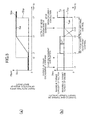
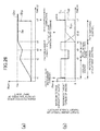
- FIG. 5 is a timing chart illustrating an example of a power-on shift-down control executed by the control device 10.
- a solid line represents an example of a change in an engine rotation speed Se.
- a dashed line represents an example of a change in a rotation speed Stn of the input shaft 31 in the next transmission mechanism Tn
- a two-dot chain line represents a rotation speed Stp of the input shaft 31 in the previous transmission mechanism Tp.
- Each of values indicated by the dashed line and the two-dot chain line is a product of the rotation speed of the input shaft 31 and a primary reduction ratio.
- a solid line represents an example of a change in a target engine torque Te.
- a dashed line represents an example of a change in a target value (that is, target torque capacity) Tch of the transmitted torque capacity of the next clutch Cn
- a two-dot chain line represents an example of a change in a target torque capacity Tcp of the previous clutch Cp.
- each of values indicated by the dashed line and the two-dot chain line is a value obtained by dividing each torque capacity by a primary reduction ratio.
- the control device 10 changes the next clutch Cn from the engaged state to the disengaged state.
- the engaged state is a state in which the transmitted torque capacity becomes maximum.
- the disengaged state is a state in which the transmitted torque capacity becomes minimum (for example, 0 Nm). Therefore, the control device 10 minimizes a target torque capacity Tcn of the next clutch Cn at t1.
- the control device 10 instructs the shift actuator 39 to move the movable gear Gn1 of the next transmission mechanism Tn toward the fixed gear Gn2 (output of a gear engagement command).
- the movable gear Gn1 of the next transmission mechanism Tn starts to move toward the fixed gear Gn2.
- the engagement of the movable gear Gn1 with the fixed gear Gn2 has been completed at t2.
- the rotation speed Stn of the input shaft 31 in the next transmission mechanism Tn increases up to a speed corresponding to the vehicle velocity at that time and the reduction ratio of the next gear level as illustrated in FIG. 5(a) .
- the control device 10 After detecting that the movable gear Gn1 is engaged with the fixed gear Gn2, the control device 10 starts the control (the above-mentioned rotation speed adjustment control) to change the engine rotation speed Se toward the next gear level corresponding speed Stg (t3).
- the control device 10 starts the rotation speed adjustment control after the movable gear Gn1 has been engaged with the fixed gear Gn2, a timing when the movable gear Gn1 collides with the fixed gear Gn2 can be prevented from matching a timing when the engine rotation speed Se arrives at the next gear level corresponding speed Stg.
- the movable gear Gn1 and the fixed gear Gn2 come close to each other in a state where a rotation speed difference is present between those gears, and can be smoothly engaged with each other.
- the control device 10 executes the following rotation speed adjustment control. As illustrated in FIG. 5(b) , the control device 10 increases the target engine torque Te of the engine 20 (t3).
- a value corresponding to the accelerator operation amount detected by the accelerator sensor 19g is set as the target engine torque Te, and the engine 20 is controlled to output the target engine torque Te (in the following description, the target engine torque corresponding to the accelerator operation amount is set as the reference target torque).
- the rotation speed adjustment control as indicated at t3 to t4 in FIG.
- a value higher than the reference target torque is set as the target engine torque Te, and the engine 20 is controlled to output the high target engine torque Te.
- the control device 10 transitions the previous clutch Cp to a semi-engaged state which is a state between the engaged state and the disengaged state (t3). Specifically, the control device 10 decreases the target torque capacity Tcp of the previous clutch Cp to a capacity corresponding to the reference target torque.
- the capacity corresponding to the reference target torque is a capacity (reference target torque x primary reduction ratio) sufficient to transmit the reference target torque.
- the control device 10 minimizes the target torque capacity Tcn of the next clutch Cn, and maintains the next clutch Cn in the disengaged state.
- an increment ( ⁇ T in FIG. 5(b) ) of the target engine torque Te relative to the reference target torque operates as the torque for increasing the engine rotation speed Se.
- the engine rotation speed Se starts to increase.
- the engine rotation speed Se arrives at the next gear level corresponding speed Stg (t4).
- the control device 10 terminates the rotation speed adjustment control, and thereafter executes a control (path switching control) to switch the path for transmitting the torque of the engine 20 to the other. Specifically, the control device 10 minimizes the target torque capacity Tcp of the previous clutch Cp, and transitions the previous clutch Cp to the disengaged state (t5). Also, the control device 10 transitions the next clutch Cn from the disengaged state to the engaged state. In the example of this drawing, the control device 10 temporarily sets the target torque capacity Tcn of the next clutch Cn to a capacity (real engine torque x primary reduction ratio) corresponding to the present real engine torque (torque actually output by the engine 20) (t6).
- a capacity real engine torque x primary reduction ratio
- the control device 10 When the next clutch Cn and the previous clutch Cp arrive at the respective target states, the control device 10 starts the movement (movement in a direction away from the fixed gear Gp2) toward the neutral position of the movable gear Gp1 of the previous transmission mechanism Tp. That is, the control device 10 outputs a gear disengagement command to the shift actuator 39. As a result, in the example of the figure, at t7, the movable gear Gp1 is moved away from the fixed gear Gp2, and eliminates their engagement. When the engagements thereof are disengaged, the driven member 42 of the previous clutch Cp and the input shaft 31 of the previous transmission mechanism Tp start to be operated simultaneously with the rotation of the crankshaft 21 and the driving member 41. As a result, the rotation speed of the input shaft 31 in the previous transmission mechanism Tp increases up to a speed corresponding to the engine rotation speed (specifically, the next gear level corresponding speed Stg) and the primary reduction ratio.
- control device 10 returns the previous clutch Cp and the next clutch Cn to the engaged state. That is, the control device 10 maximizes the target torque capacities Tcp and Tcn thereof. With this operation, the transmission control is terminated.
- FIG. 6 is a timing chart illustrating an example of a power-off shift-up control executed by the control device 10.
- the contents indicated by the respective types of lines are identical with those in FIG. 5 .
- the reference target torque is a negative value.
- the control device 10 minimizes the target torque capacity Tcn of the next clutch Cn as in the case of the power-on shift-down control. Also, the control device 10 outputs the gear engagement command at t1. As a result, the movable gear Gn1 of the next transmission mechanism Tn starts to move toward the fixed gear Gn2. In the example of the figure, the engagement of the movable gear Gn1 with the fixed gear Gn2 has been completed at t2. As illustrated in FIG.
- the control device 10 starts the rotation speed adjustment control after detecting that the movable gear Gn1 and the fixed gear Gn2 have been engaged with each other (t3).
- the control device 10 descends the target engine torque Te of the engine 20 (t3). Specifically, a value lower than the reference target torque is set as the target engine torque Te.
- the control device 10 sets the target torque capacity Tcp of the previous clutch Cp to a capacity corresponding to the reference target torque.
- the control device 10 maintains the target torque capacity Tcn of the next clutch Cn at a minimum value, and maintains the next clutch Cn in the disengaged state.
- the control device 10 executes the path switching control (operation from t4 to t7) as with the power-on shift-down control illustrated in FIG. 5 , and terminates the present power-off shift-up control.
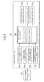
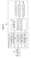
- FIG. 7 is a block diagram illustrating a function of the control device 10.
- the control device 10 includes, as its functions, a shift command determination unit 10a and a transmission control unit 10b.
- the transmission control unit 10b includes a gear control unit 10h, a clutch control unit 10i, an engine control unit 10j, a gear determination unit 10c, a target speed calculation unit 10d, a torque variation calculation unit 10e, a reference target torque calculation unit 10f, and the rotation speed control unit 10g.
- Those units are realized by allowing a CPU to execute a program stored in a memory of the control device 10.
- the shift command determination unit 10a executes processing for determining a control mode to be executed according to the shift command among the above-mentioned plurality of control modes when the shift command is issued. Specifically, the shift command determination unit 10a determines whether the contents (shift-down command/shift-up command) of the shift command, and the operation state (accelerator operation amount in this example) of the vehicle when receiving the shift command meet the start conditions of the respective control modes, or not. Then, the control mode is determined on the basis of the determination result.
- the power-on shift-down control is executed by the transmission control unit 10b.
- the power-off shift-up control is executed by the transmission control unit 10b.
- the shift-down command and the shift-up command which are the shift commands, are input to the control device 10 from the shift switch 19f according to the operation of the shift switch 19f by the rider.
- the shift-down command and the shift-up command may be generated by the control device 10 on the basis of the operation state of the vehicle and the accelerator operation of the rider without operating the shift switch 19f. For example, when the accelerator operation amount is rapidly increased, the control device 10 may generate the shift-down command.
- the transmission control unit 10b executes the transmission control according to the determination result of the shift command determination unit 10a. As described above, when the shift-down command is issued, and the accelerator operation amount is equal to or larger than the given threshold value, the transmission control unit 10b executes the power-on shift-down control. Also, when the shift-up command is issued, and the accelerator operation amount is smaller than the given threshold value, the transmission control unit 10b executes the power-off shift-up control.
- the gear control unit 10h drives the shift actuator 39 (that is, outputs a driving power of the shift actuator 39), and selectively moves the plurality of movable gears Gp1 in the previous transmission mechanism Tp, and the plurality of movable gears Gn1 in the next transmission mechanism Tn. Then, the gear control unit 10h engages the movable gear Gn1 with the fixed gear Gn2 in the next transmission mechanism Tn, and also releases the engagement of the movable gear Gp1 with the fixed gear Gp2 in the previous transmission mechanism Tp.
- the clutch control unit 10i drives the clutch actuators 49A and 49B (outputs the driving power of the clutch actuators 49A and 49B), and transitions the next clutch Cn and the previous clutch Cp to the engaged state, or the disengaged state. Also, the clutch control unit 10i sets the next clutch Cn and the previous clutch Cp in the semi-engaged state which is between the engaged state and the disengaged state, in a shifting process. In this embodiment, the clutch control unit 10i moves the clutch actuators 49A and 49B so that the actual transmitted torque capacities of the previous clutch Cp and the next clutch Cn coincide with the target torque capacities Tcp and Tcn set by the rotation speed control unit 10g.
- the engine control unit 10j controls the throttle opening degree, the fuel injection amount, and the ignition timing on the basis of the accelerator operation amount detected by the accelerator sensor 19g.
- the engine control unit 10j sets the reference target torque which is a torque corresponding to the detected accelerator operation amount as the target engine torque Te.
- the engine control unit 10j sets a torque higher or lower than the reference target torque as the target engine torque Te.
- the engine control unit 10j controls the throttle opening degree so that the actual output torque of the engine 20 matches the target engine torque Te, with reference to the map stored in the memory in advance.
- the gear determination unit 10c determines whether the movable gear Gn1 and the fixed gear Gn2 in the next transmission mechanism Tn are engaged with each other, or not. For example, the gear determination unit 10c determines whether the position of the movable gear Gn1 detected by the gear position sensor 19b arrives at the engagement position where the movable gear Gn1 is engaged with the fixed gear Gn2, or not. Also, the gear determination unit 10c may determine whether a state in which the movable gear Gn1 is disposed at the engagement position continues for a given time, or not.
- the gear determination unit 10c may determine whether the movable gear Gn1 is engaged with the fixed gear Gn2, or not, with the use of a change in the rotation speed Stn of the input shaft 31 in the next transmission mechanism Tn. For example, the gear determination unit 10c may determine whether a difference
- the gear determination unit 10c may determine that the two gears Gn1 and Gn2 are engaged with each other when the difference is smaller than the threshold value. Also, when the state in which the difference is smaller than the threshold value continues for a time longer than the given time, the gear determination unit 10c may determine that the two gears Gn1 and Gn2 are engaged with each other.
- the gear determination unit 10c also determines whether the engagement of the movable gear Gp1 with the fixed gear Gp2 in the previous transmission mechanism Tp is released, or not. This determination can be also conducted on the basis of the output signal of the gear position sensor 19b, or the rotation speed Stp of the input shaft 31. For example, the gear determination unit 10c determines whether the movable gear Gp1 is disposed in the neutral position, or not, on the basis of the output signal of the gear position sensor 19b.
- the gear determination unit 10c determines that the engagement of the movable gear Gp1 with the fixed gear Gp2 is released when the movable gear Gp1 is disposed at the neutral position, or when a state in which the movable gear Gp1 is disposed at the neutral position continues for the given time or longer.
- the target speed calculation unit 10d calculates the engine rotation speed to be reached under the rotation speed adjustment control. That is, the target speed calculation unit 10d calculates the above-mentioned next gear level corresponding speed Stg.
- the target speed calculation unit 10d sets, for example, a product (Sout ⁇ Rnext ⁇ R1) of the rotation speed (Sout) of the output shaft 32 detected by the output side rotation sensor 19e before starting the rotation speed adjustment control, the reduction ratio (Rnext) of the next gear level, and the primary reduction ratio (R1) as the next gear level corresponding speed Stg.
- the torque variation calculation unit 10e calculates a torque (hereinafter referred to as "necessary torque variation”) necessary to increase or decrease the engine rotation speed Se toward the next gear level corresponding speed Stg in the rotation speed adjustment control.
- the necessary torque variation is, for example, an inertia torque of the engine 20 which is generated when increasing or decreasing the engine rotation speed Se to the next gear level corresponding speed Stg.
- the necessary torque variation is calculated on the basis of the actual engine rotation speed Se when starting the rotation speed adjustment control, the next gear level corresponding speed Stg, and the time (time from t3 to t4 in FIGS. 5 and 6 , hereinafter referred to as "adjustment control time ( ⁇ t)" during which the rotation speed adjustment control is executed.
- the necessary torque variation is calculated on the basis of the adjustment control time to adjust the time spent for the rotation speed adjustment control.
- the adjustment control time is calculated with reference to a map (hereinafter referred to as "adjustment time map" provided in, for example, control device 10.
- the adjustment control time is associated with the contents (previous gear level and next gear level) of the shift command and the accelerator operation amount.
- the adjustment control time is set to be shorter as the accelerator operation amount is increased more.
- the torque variation calculation unit 10e calculates the adjustment control time on the basis of the contents of the shift command, and the accelerator operation amount detected by the accelerator sensor 19g.
- the adjustment control time is not limited to this example.
- the adjustment control time may be a fixed value.
- the adjustment control time ( ⁇ t) may be calculated on the basis of another value indicative of the operation state of the vehicle.
- the method of calculating the necessary torque variation is not limited to this example.
- the adjustment control time may not be used for calculation of the necessary torque variation.
- the necessary torque variation may be calculated directly from the map that associates the accelerator operation amount and the contents of the gear levels with the necessary torque variation.
- the necessary torque variation may be a predetermined value.
- the reference target torque calculation unit 10f calculates the above-mentioned reference target torque on the basis of the accelerator operation amount.
- the map (torque map) that associates the accelerator operation amount, the engine rotation speed, and the engine torque with each other is stored in the memory of the control device 10 in advance.
- the reference target torque calculation unit 10f calculates the reference target torque with reference to the torque map. That is, the reference target torque calculation unit 10f calculates the engine torque corresponding to the accelerator operation amount and the engine rotation speed Se, which are detected by the sensors, as the reference target torque.
- the reference target torque is set as the target engine torque Te.
- the reference target torque calculation unit 10f calculates the reference target torque for a given time. Therefore, not only in the normal travel, but also during shifting (including the duration of the rotation speed adjustment control), the target torque capacity Tcp of the previous clutch Cp and the target engine torque Te are gradually changed according to a change in the accelerator operation amount.
- the rotation speed control unit 10g operates the engine control unit 10j and the clutch control unit 10i to execute the rotation speed adjustment control.
- the rotation speed control unit 10g increases or decreases the engine rotation speed Se toward the next gear level corresponding speed Stg. Specifically, during the power-on shift-down, the rotation speed control unit 10g makes the target engine torque Te larger than the reference target torque, and decreases the transmitted torque capacities of the clutches Cp and Cn. As a result, the rotation speed control unit 10g can increase the engine rotation speed Se toward the next gear level corresponding speed Stg while suppressing a fluctuation of the torque which is transmitted to the rear wheel 3.
- the rotation speed control unit 10g makes the target engine torque Te smaller than the reference target torque, and decreases the transmitted torque capacities of the clutches Cp and Cn. As a result, the rotation speed control unit 10g can decrease the engine rotation speed Se toward the next gear level corresponding speed Stg while suppressing a fluctuation of the torque which is transmitted to the rear wheel 3.
- the rotation speed control unit 10g executes the increase control and the decrease control as the rotation speed adjustment control.
- the increase control is a control for increasing the engine rotation speed Se up to the next gear level corresponding speed Stg (control in t3 to t4 in FIG. 5 ).
- the rotation speed control unit 10g makes the target engine torque Te at the time of executing the increase control higher than the reference target torque by the necessary torque variation.
- the engine 20 outputs the torque higher than the reference target torque by the necessary torque variation in the rotation speed adjustment control.
- the rotation speed control unit 10g sets the target torque capacity Tcp of the previous clutch Cp to a capacity corresponding to the reference target torque.
- the capacity corresponding to the reference target torque is, for example, a torque (reference target torque x primary reduction ratio) needed to transmit the reference target torque as described above.
- the rotation speed control unit 10g minimizes the target torque capacity Tcn of the next clutch Cn (for example, 0 Nm). As a result, the necessary torque variation operates as the torque for increasing the engine rotation speed Se.
- the method for increasing the engine rotation speed Se is not limited to the above example.
- the target engine torque Te in the increase control may be, for example, a sum of a value obtained by further correcting the reference target torque corresponding to the accelerator operation amount, and the necessary torque variation.
- the capacity corresponding to the corrected value is the target torque capacity Tcp of the previous clutch Cp.
- the decrease control is a control for decreasing the engine rotation speed Se down to the next gear level corresponding speed Stg (control in t3 to t4 in FIG. 6 ).
- the rotation speed control unit 10g makes, for example, the target engine torque Te at the time of executing the decrease control lower than the reference target torque by an absolute value of the necessary torque variation.
- the engine 20 outputs the torque lower than the reference target torque by the necessary torque variation in the rotation speed adjustment control.
- the target engine torque Te at the time of executing the decrease control can be calculated as a sum of the reference target torque and the necessary torque variation.
- the rotation speed control unit 10g sets the target torque capacity Tcp of the previous clutch Cp to a capacity corresponding to the reference target torque. Also, the rotation speed control unit 10g minimizes the target torque capacity Tcn of the next clutch Cn (for example, 0 Nm). As a result, the necessary torque variation operates as the torque for decreasing the engine rotation speed Se.
- the rotation speed control unit 10g may conduct the following process according to a magnitude of the reference target torque.
- the rotation speed control unit 10g compares a sum (Tnml + ⁇ Ta) of a reference target torque (Tnml) and a necessary torque variation ( ⁇ Ta) with a minimum torque. Then, the rotation speed control unit 10g sets any higher one as a target engine torque Te.
- the rotation speed control unit 10g compares the sum (Tnml + ⁇ Ta) of the reference target torque (Tnml) and the necessary torque variation ( ⁇ Ta) with a maximum torque.
- the rotation speed control unit 10g sets any lower one as the target engine torque Te. Also, the rotation speed control unit 10g calculates the target torque capacity Tcp of the previous clutch Cp on the basis of the target engine torque Te and the necessary torque variation. For example, a capacity ((
- ) ⁇ primary reduction ratio) corresponding to a value obtained by subtracting an absolute value of the necessary torque variation ( ⁇ Ta) from the absolute value of the target engine torque Te is set as the target torque capacity Tcp.
- FIG. 8 is a timing chart illustrating an outline of the decrease control executed when the reference target torque is the minimum torque. Differences from the timing chart illustrated in FIG. 6 will be mainly described.
- the minimum torque is the reference target torque corresponding to the accelerator operation amount. For that reason, in both of the normal engine control and the decrease control before the decrease control (t3 to t4) starts, the minimum torque is set as the target engine torque Te.
- the capacity corresponding to a value lower than the torque capacity corresponding to the minimum torque by the absolute value of the necessary torque variation is set as the target torque capacity Tcp of the previous clutch Cp. That is, the capacity needed to transmit the torque of the difference between the absolute value of the minimum torque and the absolute value of the necessary torque variation is set as the target torque capacity Tcp.
- the torque transmitted to the engine 20 from a downstream side of the previous clutch Cp is reduced to decrease the engine rotation speed Se.
- the rotation speed control unit 10g prevents the engine rotation speed Se from arriving at the next gear level corresponding speed Stg until the movable gear Gn1 and the fixed gear Gn2 are engaged with each other. Specifically, the rotation speed control unit 10g executes the above-described increase control or decrease control after the engagement of the gears Gn1 and Gn2 has been completed. Also, in another example, the rotation speed control unit 10g temporarily suspends the above-mentioned increase control or decrease control until the engagement of the gears Gn1 and Gn2 has been completed.
- the reference target torque calculation unit 10f calculates the reference target torque for a given time. For that reason, when the accelerator operation amount is changed during the rotation speed adjustment control, the reference target torque is also changed. In this case, the target engine torque Te set by the rotation speed control unit 10g is also changed, and the target torque capacity Tcp determined on the basis of the reference target torque is also changed.
- FIG. 9 is a flowchart illustrating an example of processing to be executed in the power-on shift-down control and the power-off shift-up control.
- the clutch control unit 10i minimizes the target torque capacity Tcn of the next clutch Cn (S101). That is, the clutch control unit 10i transitions the next clutch Cn to the disengaged state. Then, the gear control unit 10h outputs a gear engagement command for instructing the movable gear Gn1 to move toward the fixed gear Gn2 in the next transmission mechanism Tn (S102). That is, the gear control unit 10h brings the movable gear Gn1 and the fixed gear Gn2 closer to each other. Then, the gear determination unit 10c determines whether the movable gear Gn1 is engaged with the fixed gear Gn2, or not (S103). The gear determination unit 10c repeats the processing of S103 until the movable gear Gn1 is engaged with the fixed gear Gn2.
- the torque variation calculation unit 10e calculates the necessary torque variation (S104), and the rotation speed control unit 10g executes the rotation speed adjustment control (the increase control or the decrease control) (S10S). Specifically, the rotation speed control unit 10g executes the increase control in the power-on shift-down, and executes the decrease control in the power-off shift-up.
- the increase control and the decrease control start after it is determined in S103 that the movable gear Gn1 and the fixed gear Gn2 have engaged with each other, the movable gear Gn1 and the fixed gear Gn2 are smoothly engaged with each other.
- the rotation speed control unit 10g determines whether the engine rotation speed Se arrives at the next gear level corresponding speed Stg, or not (S106). That is, the rotation speed control unit 10g determines whether the rotation speed difference between the driving member 41 and the driven member 42 in the next clutch Cn is eliminated, or not. The rotation speed control unit 10g executes the increase control of S105 until the engine rotation speed Se arrives at the next gear level corresponding speed Stg.
- the rotation speed control unit 10g determines whether the engine rotation speed Se arrives at the next gear level corresponding speed Stg, or not, on the basis of a value (for example, the difference per se, or a ratio of those speeds) corresponding to the difference between the engine rotation speed Se and the next gear level corresponding speed Stg. For example, the rotation speed control unit 10g determines whether the absolute value of the difference between the engine rotation speed Se and the next gear level corresponding speed Stg is smaller than a sufficiently small threshold value, or not.
- a value for example, the difference per se, or a ratio of those speeds
- the rotation speed control unit 10g terminates the increase control, and returns the target engine torque Te to the reference target torque (step 107). Then, the control device 10 terminates the present transmission control after having executed the path switching control (control in t4 to t7 in FIGS. 5 and 6 ) (S108).
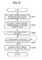
- FIG. 10 is a flowchart illustrating an example of processing to be executed in the path switching control.
- the clutch control unit 10i starts to transition the previous clutch Cp toward the disengaged state, in response to an arrival of the engine rotation speed Se at the next gear level corresponding speed Stg.
- the clutch control unit 10i sets the target torque capacity Tcp of the previous clutch Cp to a capacity (for example, minimum value 0 (hereinafter referred to as "gear disengagement capacity") as large as the engagement of the gears Gp1 and Gp2 of the previous transmission mechanism Tp can be released (S201).
- the clutch control unit 10i starts the transition of the next clutch Cn toward the engaged state in response to the arrival of the engine rotation speed Se at the next gear level corresponding speed Stg.
- the clutch control unit 10i sets the target torque capacity Tcn of the next clutch Cn to a capacity (present engine torque x primary reduction ratio) corresponding to the torque (hereinafter referred to as "present engine torque") which is presently output by the engine 20 (S202). As a result, the present engine rotation speed is maintained.
- the gear control unit 10h After the sensor detects that the previous clutch Cp is set to the gear disengagement capacity, and the capacity of the next clutch Cn is set to the capacity corresponding to the present engine torque, the gear control unit 10h starts the movement of the movable gear Gp1 toward the neutral position in the previous transmission mechanism Tp (movement in a direction away from the fixed gear Gp2) . That is, the gear control unit 10h outputs a gear disengagement command to the shift actuator 39 (S203). Thereafter, the gear determination unit 10c determines whether the engagement of the movable gear Gp1 and the fixed gear Gp2 is released, or not (S204) .
- the clutch control unit 10i returns both of the previous clutch Cp and the next clutch Cn to the normal state after the engagement of the movable gear Gp1 and the fixed gear Gp2 has been released. That is, the clutch control unit 10i maximizes the target torque capacity Tcp of the previous clutch Cp, and the target torque capacity Tcn of the next clutch Cn (S205). As a result, the path switching control is terminated.
- the rotation speed adjustment control is executed. For that reason, the movable gear Gn1 and the fixed gear Gn2 in the next transmission mechanism Tn can be smoothly engaged with each other.
- the rotation speed control unit 10g starts the rotation speed adjustment control (increase control or decrease control) before the engagement of the movable gear Gn1 and the fixed gear Gn2 has been completed. Then, the rotation speed control unit 10g maintains the engine rotation speed Se at a rotation speed (hereinafter referred to as "maintained rotation speed") between the engine rotation speed before the shift command is issued, and the next gear level corresponding speed Stg until the engagement of the movable gear Gn1 and the fixed gear Gn2 has been completed.
- maintained rotation speed a rotation speed
- the rotation speed control unit 10g starts the increase control according to the shift command, and maintains the engine rotation speed Se at the rotation speed lower than the next gear level corresponding speed Stg until the gears Gn1 and Gn2 are engaged with each other. Also, in the power-off shift-up, the rotation speed control unit 10g starts the decrease control according to the shift command, and maintains the engine rotation speed Se at the rotation speed higher than the next gear level corresponding speed Stg until the gears Gn1 and Gn2 are engaged with each other.
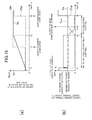
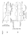
- FIG. 11 is a timing chart illustrating an outline of the power-on shift-down control according to this example.
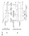
- FIG. 12 is a timing chart illustrating an outline of the power-off shift-up control according to this example.
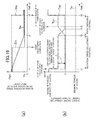
- the contents indicated by the respective types of lines are identical with those in FIG. 5 .
- the reference target torque is set to the minimum torque.
- the gear control unit 10h outputs the gear engagement command.
- the movable gear Gn1 of the next transmission mechanism Tn starts to move toward the fixed gear Gn2.
- the engagement of the movable gear Gn1 and the fixed gear Gn2 has been completed at t3.
- the rotation speed Stn of the input shaft 31 in the next transmission mechanism Tn increases or decreases to the rotation speed corresponding to the vehicle velocity at that time and the reduction ratio of the next gear level.
- the rotation speed control unit 10g starts the rotation speed adjustment control without waiting for the engagement completion of the movable gear Gn1 and the fixed gear Gn2 in the next transmission mechanism Tn (before the engagement completion) .
- the rotation speed control unit 10g starts the rotation speed adjustment control at t1. That is, the rotation speed control unit 10g starts the rotation speed adjustment control at the same time of outputting the gear engagement command.
- the rotation speed control unit 10g executes the increase control in the power-on shift-down control illustrated in FIG. 11
- the rotation speed control unit 10g executes the decrease control in the power-off shift-up control illustrated in FIG. 12 . For that reason, the engine rotation speed Se starts to increase or decrease from t1 (refer to FIG. 11 and FIG. 12(a) ).
- the target torque capacity Tcp of the previous clutch Cp is set to the capacity corresponding to the reference target torque.
- the reference target torque is the minimum torque.
- the target engine torque Te is set to the minimum torque
- the target torque capacity Tcp of the previous clutch Cp is set to the capacity corresponding to a value obtained by subtracting the absolute value of the necessary torque variation from the absolute value of the minimum torque.
- the target torque capacity Tcn of the next clutch Cn is set to the minimum value by starting the increase control or the decrease control.
- the engine rotation speed Se After the engine rotation speed Se starts to increase or decrease at t1, the engine rotation speed Se arrives at the maintained rotation speed set between the next gear level corresponding speed Stg and the engine rotation speed before shifting at t2 .
- the maintained rotation speed is a speed calculated according to the next gear level corresponding speed Stg.
- the maintained rotation speed is a rotation speed lower than the next gear level corresponding speed Stg by a given value.
- the maintained rotation speed is a rotation speed higher than the next gear level corresponding speed Stg by a given value.
- the given value may be a predetermined fixed value, or a value varied according to the necessary torque variation or the contents of the shift command (the previous gear level and the next gear level).
- the rotation speed control unit 10g temporarily stops the increase control or the decrease control that starts at t1, and executes a control (hereinafter referred to as "maintenance control") to maintain the engine rotation speed Se at the present engine rotation speed (the maintained rotation speed in this example).
- the rotation speed control unit 10g sets, for example, the reference target torque as the target engine torque Te, and sets the target torque capacity Tcp of the previous clutch Cp to the capacity corresponding to the reference target torque.
- the rotation speed control unit 10g sets the target torque capacity Tcn of the next clutch Cn to a minimum value. As a result, since the overall output torque of the engine 20 is transmitted toward the rear wheel 3 through the previous clutch Cp, a change in the engine rotation speed Se can be suppressed.
- the rotation speed control unit 10g again executes the increase control or the decrease control (t4). That is, in the power-on shift-down control of FIG. 11 , the increase control is executed. Also, in the power-off shift-up control of FIG. 12 , the decrease control is executed. As a result, the engine rotation speed Se again starts to increase or decrease, and arrives at the next gear level corresponding speed Stg at t5. Thus, the rotation speed control unit 10g temporarily suspends the increase control or the decrease control to prevent the engine rotation speed Se from matching the next gear level corresponding speed Stg before the engagement of the movable gear Gn1 and the fixed gear Gn2 has been completed.
- control device 10 executes the path switching control, and terminates the present transmission control, as with the processing illustrated in FIGS. 5 and 6 (t8).
- FIG. 13 is a flowchart illustrating an example of processing to be executed in the power-on shift-down control and the power-off shift-up control according to this example.
- the gear control unit 10h outputs the gear engagement command (S301). Also, the torque variation calculation unit 10e calculates the necessary torque variation (S302). Then, the rotation speed control unit 10g executes the rotation speed adjustment control (the increase control and the decrease control) on the basis of the necessary torque variation and the reference target torque without waiting for the engagement completion of the movable gear Gn1 and the fixed gear Gn2 (S303). The rotation speed adjustment control starts subsequent to the output of the gear engagement command in S301. In the power-on shift-down control, the rotation speed control unit 10g executes the increase control in S303, and in the power-off shift-up control, the rotation speed control unit 10g executes the decrease control in S303.
- the rotation speed control unit 10g determines whether the movable gear Gn1 is engaged with the fixed gear Gn2 in the next transmission mechanism Tn, or not (S304). In this situation, if the movable gear Gn1 has not yet been engaged with the fixed gear Gn2, the rotation speed control unit 10g determines whether the engine rotation speed Se has arrived at the maintained rotation speed, or not (S305). if the engine rotation speed Se has not yet arrived at the maintained rotation speed in the determination of S305, the rotation speed control unit 10g continues the increase control or the decrease control (S303).
- the rotation speed control unit 10g executes the maintenance control of the engine rotation speed Se (S306). As a result, the increase or decrease of the engine rotation speed Se stops, and the engine rotation speed Se remains at the maintained rotation speed. Thereafter, the processing returns to S304, and it is again determined whether the movable gear Gn1 and the fixed gear Gn2 have been engaged with each other, or not.
- the rotation speed control unit 10g determines whether the engine rotation speed Se has arrived at the next gear level corresponding speed Stg, or not (S307). In this case, if the engine rotation speed Se has not yet arrived at the next gear level corresponding speed Stg, the rotation speed control unit 10g restarts or continues the increase control or the decrease control (S303). On the other hand, if the engine rotation speed Se has already arrived at the next gear level corresponding speed Stg in S307, the rotation speed control unit 10g sets the reference target torque as the target engine torque Te (S308). Then, after the control device 10 has executed the above-mentioned path switching control (S309), the control device 10 terminates the present transmission control.
- the rotation speed control unit 10g starts the increase control or the decrease control. For that reason, since a change in the engine rotation speed Se can early start, a time lag between the shift command from the rider and a change in the driving of the engine 20 attributable to the shift command can be reduced, and the operational feeling of the vehicle during shifting can be improved.
- the maintained rotation speed is calculated on the basis of the next gear level corresponding speed. For that reason, a variation in a time required until the engine rotation speed Se is changed from the maintained rotation speed to the next gear level corresponding speed can be suppressed.
- the above-mentioned rotation speed adjustment control that prevents the engine rotation speed Se from arriving at the next gear level corresponding speed Stg until the engagement of the movable gear Gn1 and the fixed gear Gn2 in the next transmission mechanism Tn has been completed, is selectively executed according to the contents of the shift command, and the variation of the engine rotation speed Se needed to arrive at the next gear level corresponding speed Stg.
- the rotation speed control unit 10g has two modes as the control modes.
- a first control is the above-mentioned rotation speed adjustment control for preventing the engine rotation speed Se from arriving at the next gear level corresponding speed Stg until the engagement of the gears Gn1 and Gn2 in the next transmission mechanism Tn has been completed.
- a second control is a control for changing the engine rotation speed Se toward the next gear level corresponding speed Stg, independently from the determination of whether the gears Gn1 and Gn2 are engaged with each other, or not. That is, in the second control, the above-mentioned increase control or decrease control starts, without conducting the determination of whether the gears Gn1 and Gn2 are engaged with each other, or not, or without depending on the determination result. Thereafter, the increase control or the decrease control continues to be conducted until the engine rotation speed Se arrives at the next gear level corresponding speed Stg.
- the rotation speed control unit 10g selectively executes the first control and the second control on the basis of the variation of the engine rotation speed Se needed to arrive at the next gear level corresponding speed Stg. That is, the rotation speed control unit 10g selects any one of the first control and the second control on the basis of a difference between the engine rotation speed before starting the rotation speed adjustment control and the next gear level corresponding speed Stg. If the rotation speed variation needed to arrive at the next gear level corresponding speed Stg is large (that is, when the next gear level corresponding speed Stg is largely away from the engine rotation speed before starting the rotation speed adjustment control), a long time is required until the engine rotation speed Se arrives at the next gear level corresponding speed Stg.
- the rotation speed control unit 10g executes the first control.
- the rotation speed control unit 10g executes the second control. According to the second control, the engine rotation speed Se can early arrive at the next gear level corresponding speed Stg.
- FIG. 14 is a flowchart illustrating an example of processing to be executed in the power-on shift-down control and the power-off shift-up control according to this example.
- the control device 10 determines whether the variation of the engine rotation speed Se needed to arrive at the next gear level corresponding speed Stg is larger than a threshold value, or not. Specifically, the control device 10 determines whether the difference (hereinafter referred to as "scheduled variation") between the engine rotation speed (the engine rotation speed at the present or immediately before shifting) and the next gear level corresponding speed Stg is larger than a threshold value (hereinafter referred to as "mode determination threshold value”), or not (S401).
- a threshold value hereinafter referred to as "mode determination threshold value”
- the first control is executed (S402).
- the processing in S101 to S107 illustrated in FIG. 9 is executed.
- the processing in S301 to S308 illustrated in FIG. 13 may be executed.
- the processing in and after S403, which is the second control is executed.
- the gear control unit 10h outputs the gear engagement command (S403).
- the torque variation calculation unit 10e calculates the necessary torque variation (S404), and the rotation speed control unit 10g executes the increase control or the decrease control on the basis of the necessary torque variation and the reference target torque without detecting the engagement completion of the movable gear Gn1 and the fixed gear Gn2 (S405). That is, the rotation speed control unit 10g executes the increase control in the power-on shift-down, and the decrease control in the power-off shift-up.
- the rotation speed control unit 10g determines whether the engine rotation speed Se has arrived at the next gear level corresponding speed Stg, or not (S406). In this example, if the engine rotation speed Se has not yet arrived at the next gear level corresponding speed Stg, the rotation speed control unit 10g continues the increase control or the decrease control in S405. On the other hand, if the engine rotation speed Se has already arrived at the next gear level corresponding speed Stg, the rotation speed control unit 10g terminates the increase control or the decrease control, and returns the target engine torque Te to the reference target torque (S407). Also, the gear determination unit 10c determines whether the movable gear Gn1 has been engaged with the fixed gear Gn2 in the next transmission mechanism Tn, or not (S408). In this case, if it is determined that the movable gear Gn1 is engaged with the fixed gear Gn2, the control device 10 executes the above-mentioned path switching control (S409), and terminates the present transmission control.
- FIG. 15 is a timing chart illustrating an example of a change in the engine rotation speed when the above-mentioned second control is executed in the power-on shift-down.
- FIG. 16 is a timing chart illustrating an example of a change in the engine rotation speed when the above-mentioned second control is executed in the power-off shift-up (control).
- the contents indicated by the respective types of lines are identical with those in FIG. 5 .
- , target torque capacity Tcn of next clutch Cn minimum value).
- the engine rotation speed Se starts to change toward the next gear level corresponding speed Stg by the increase control or the decrease control (refer to FIGS. 15 (a) and 16 (a) ).
- the increase control and the decrease control continue without stopping on the way until the engine rotation speed Se arrives at the next gear level corresponding speed Stg at t3.
- timing t2 when the movable gear Gn1 is engaged with the fixed gear Gn2 is earlier than timing t3 when the engine rotation speed Se arrives at the next gear level corresponding speed Stg.
- the rotation speed adjustment control is terminated. Thereafter, the same path switching control as that at and after t4 in FIG. 5 is executed, and the present transmission control is terminated at t6.
- the control device 10 may determine whether such collision of the dog clutches is generated, or not. Then, the rotation speed control unit 10g may continue or restart a change in the engine rotation speed Se according to the determination result. With this configuration, the relative position of the movable gear Gn1 and the fixed gear Gn2 can be changed, and the dog teeth can be fitted into the dog holes.
- the rotation speed control unit 10g stops the maintenance control, and restarts the increase control or the decrease control.
- FIG. 17 is a block diagram illustrating a function of the control device 10 in this example.
- the control device 10 includes a collision determination unit 10k in addition to the rotation speed control unit 10g described above.
- the collision determination unit 10k determines whether the dog clutches collide with each other, or not.
- the collision determination unit 10k determines whether the dog clutches collide with each other, nor not, on the basis of the position of the movable gear Gn1, which is detected by, for example, the gear position sensor 19b. For example, when the movable gear Gn1 stays at a position between the engagement position at which the movable gear Gn1 is engaged with the fixed gear Gn2, and the neutral position for a given time or longer, the collision determination unit 10k determines that the dog clutches collide with each other. This processing of the collision determination unit 10k continues until the engagement of the movable gear Gn1 and the fixed gear Gn2 has been completed.
- the processing of the collision determination unit 10k may be conducted as follows.
- the rotation speed Stn of the input shaft 31 in the next transmission mechanism Tn increases or decreases, and arrives at the rotation speed corresponding to the vehicle velocity and the reduction ratio of the next gear level.
- the collision determination unit 10k may determine whether the dog clutches collide with each other, or not, on the basis of the rotation speed Stn of the input shaft 31 in the next transmission mechanism Tn.
- the collision determination unit 10k may determine that the dog clutches collide with each other.
- FIG. 18 is a timing chart illustrating a change in the engine rotation speed when the control is executed according to this example.
- the contents indicated by the respective types of lines are identical with those in FIG. 5 .
- the gear control unit 10h outputs the gear engagement command. Also, the rotation speed control unit 10g starts the increase control at t1. As a result, as illustrated in FIG. 18(a) , the engine rotation speed Se starts to increase. In this example, at t2, the dog clutches collide with each other between the movable gear Gn1 and the fixed gear Gn2. The increase control continues until the collision of the dog clutches is eliminated even after the engine rotation speed Se has arrived at the next gear level corresponding speed Stg. As a result, the engine rotation speed Se exceeds the next gear level corresponding speed Stg.
- the rotation speed control unit 10g executes a control (hereinafter referred to as "return control") to return the engine rotation speed Se to the next gear level corresponding speed Stg.
- return control a control
- the rotation speed control unit 10g sets the target engine torque Te to a torque lower than the reference target torque while maintaining the target torque capacity Tcp of the previous clutch Cp at the capacity corresponding to the reference target torque.
- the engine rotation speed Se starts to decrease, and the engine rotation speed Se matches the next gear level corresponding speed Stg at t4.
- the above-mentioned path switching control is executed (t4 to t7), and the present transmission control is terminated.
- FIG. 19 is a flowchart illustrating processing to be executed by the control device 10 in this example.
- the same processing as the processing illustrated in FIG. 14 is indicated by identical symbol, and a description thereof will be omitted.
- the collision determination unit 10k determines whether the dog clutches collide with each other between the movable gear Gn1 and the fixed gear Gn2 (S410). In this example, if the dog clutches do not collide with each other, it is determined by the gear determination unit 10c whether the movable gear Gn1 has been engaged with the fixed gear Gn2, or not (S408). If the movable gear Gn1 has not yet been engaged with the fixed gear Gn2, the rotation speed control unit 10g executes the above-mentioned maintenance control (refer to S306 in FIG. 13 ), and maintains the present engine rotation speed Se (S412).
- the rotation speed control unit 10g continues or restarts the increase control or the decrease control in S405, and changes the engine rotation speed Se. That is, the increase control is executed in S405 in the power-on shift-down control, and the decrease control is executed in S405 in the power-off shift-up control.
- the increase control or the decrease control in S405 is continued until the collision of the dog clutches is eliminated.
- the rotation speed difference can be generated between the movable gear Gn1 and the fixed gear Gn2.
- the collision of the dog clutches can be eliminated in a shorter time than that when the rotation speed difference is not generated, and the movable gear Gn1 and the fixed gear Gn2 can be engaged with each other.
- the rotation speed control unit 10g executes the return control to return the engine rotation speed Se to the next gear level corresponding speed Stg (S412).
- FIG. 20 is a flowchart illustrating an example of processing to be executed in the return control of the engine rotation speed.
- the return control changes the engine rotation speed Se that exceeds the next gear level corresponding speed Stg as a result of the increase control or the decrease control toward the next gear level corresponding speed Stg.
- the rotation speed control unit 10g first determines whether the engine rotation speed Se has already matched the next gear level corresponding speed Stg, or not (S501). In this situation, if the engine rotation speed Se does not match the next gear level corresponding speed Stg, the rotation speed control unit 10g determines whether the engine rotation speed Se is higher than the next gear level corresponding speed Stg, or not (S502). If the engine rotation speed Se is higher than the next gear level corresponding speed Stg, the rotation speed control unit 10g executes a second decrease control to reduce the engine rotation speed Se toward the next gear level corresponding speed Stg (S503).
- the second decrease control is conducted, for example, as follows.
- the rotation speed control unit 10g reduces the target engine torque Te by a given value as compared with the reference target torque.
- the given value is, for example, a fixed value.
- the given value may be calculated on the basis of the necessary torque variation, the contents (the next gear level and the previous gear level) of the shift command, or a speed adjustment time used when calculating the necessary torque variation.
- the rotation speed control unit 10g maintains the target torque capacity Tcp of the previous clutch Cp at the capacity corresponding to the reference target torque. Further, the rotation speed control unit 10g maintains the target torque capacity of the next clutch Cn at a minimum value 0.
- the rotation speed control unit 10g executes a second increase control to increase the engine rotation speed Se toward the next gear level corresponding speed Stg (S504).
- the second increase control is conducted, for example, as follows.
- the rotation speed control unit 10g increases the target engine torque Te by a given value as compared with the reference target torque.
- the given value may be also a fixed value like the given value in the second decrease control, or may be calculated on the basis of the necessary torque variation.
- the rotation speed control unit 10g maintains the target torque capacity Tcp of the previous clutch Cp at the capacity corresponding to the reference target torque, and maintains the target torque capacity of the next clutch Cn at a minimum value.
- the rotation speed control unit 10g terminates the second decrease control or the second increase control, and sets the target engine torque Te to the reference target torque (S505).
- the above processing is an example of the return control.
- the rotation speed control unit 10g continues or restarts to change the engine rotation speed Se according to the determination result of the collision determination unit 10k. For that reason, even if the dog clutches collide with each other, the collision can be eliminated to early engage the movable gear Gn1 with the fixed gear Gn2 in a short time.
- the rotation speed control unit 10g executes the control to return the engine rotation speed Se to the next gear level corresponding speed Stg. For that reason, even if the dog clutches collide with each other, the engine rotation speed Se can match the next gear level corresponding speed Stg, and the shifting shock can be reduced.
- the rotation speed control unit 10g changes the engine rotation speed Se to the rotation speed (hereinafter referred to as "excess rotation speed") that exceeds the next gear level corresponding speed Stg. Then, the gear control unit 10h moves the movable gear Gn1 so that the movable gear Gn1 of the next transmission mechanism Tn is abutted against the fixed gear Gn2 after the engine rotation speed Se exceeds the next gear level corresponding speed Stg. In other words, the rotation speed control unit 10g prevents the engine rotation speed Se from returning to the next gear level corresponding speed Stg from the excess rotation speed until the engagement of the movable gear Gn1 and the fixed gear Gn2 has been completed.
- the movable gear Gn1 and the fixed gear Gn2 can be smoothly engaged with each other. Also, since the change in the engine rotation speed Se can be early started, a time lag between the shift command from the rider and a change in the driving of the engine 20 attributable to the shift command can be reduced, and the operational feeling of the vehicle during shifting can be improved.
- the control device 10 according to the second embodiment also has the respective functions illustrated in FIG. 7 .
- FIG. 21 is a timing chart illustrating an outline of a power-on shift-down control according to this configuration.
- FIG. 22 is a timing chart illustrating an outline of a power-off shift-up control according to this configuration.
- the contents indicated by the respective types of lines are identical with those in FIG. 5 .
- the target torque capacity Tcp of the previous clutch Cp is set to the capacity corresponding to the difference between the minimum torque and the necessary torque variation. Further, the target torque capacity Tcn of the next clutch Cn is set to the minimum value 0 as with the increase control.
- the rotation speed control unit 10g continues the increase control or the decrease control even after the engine rotation speed Se has arrived at the next gear level corresponding speed Stg, and as illustrated in FIGS. 21 (a) and 22 (a) , the engine rotation speed Se increases or decreases over the next gear level corresponding speed Stg. Then, at t3, the engine rotation speed Se arrives at the excess rotation speed set over the next gear level corresponding speed Stg.
- the excess rotation speed is a value higher than the next gear level corresponding speed in the power-on shift-down control, and a value lower than the next gear level corresponding speed in the power-off shift-up control.
- the rotation speed control unit 10g terminates the increase control or the decrease control, and starts the above-mentioned maintenance control.
- the gear control unit 10h starts to move the movable gear Gn1 so that the movable gear Gn1 is abutted against the fixed gear Gn2 in the next transmission mechanism Tn under the circumstances where the engine rotation speed Se is higher than the next gear level corresponding speed Stg.
- the gear control unit 10h outputs the gear engagement command slightly after timing when the engine rotation speed Se arrives at the next gear level corresponding speed Stg (t2).
- the movable gear Gn1 is abutted against the fixed gear Gn2, and engaged with the fixed gear Gn2 in a status in which the engine rotation speed Se is a rotation speed higher than the next gear level corresponding speed Stg (t4).
- a timing (that is, movement start timing of the movable gear Gn1) when the gear control unit 10h outputs the gear engagement command may be appropriately set according to the operation speed of the shift actuator 39. For example, when the operation speed of the shift actuator 39 is low, the gear control unit 10h may start to move the movable gear Gn1 earlier than the timing when the engine rotation speed Se arrives at the next gear level corresponding speed Stg.
- the rotation speed control unit 10g When the movable gear Gn1 is engaged with the fixed gear Gn2 at t4, the rotation speed control unit 10g starts the return control to return the engine rotation speed Se to the next gear level corresponding speed Stg, as illustrated in FIGS. 21 (b) and 22 (b) .
- the rotation speed control unit 10g executes the second decrease control described with reference to FIG. 20 as the return control.
- the target engine torque Te is set to a torque lower than the reference target torque.
- the target torque capacity Tcp of the previous clutch Cp is set to a capacity corresponding to the reference target torque, and the target torque capacity of the next clutch Cn is set to the minimum value 0.
- the rotation speed control unit 10g executes the second increase control described with reference to FIG. 20 as the return control.
- the target engine torque Te is set to a torque higher than the reference target torque.
- the target torque capacity Tcp of the previous clutch Cp is set to a capacity corresponding to the reference target torque, and the target torque capacity of the next clutch Cn is set to the minimum value 0.
- the engine rotation speed Se increases or decreases toward the next gear level corresponding speed Stg by the second decrease control or the second increase control, and arrives at the next gear level corresponding speed Stg at t5.
- the rotation speed control unit 10g returns the target engine torque Te to the reference target torque.
- the decrease or increase of the engine rotation speed Se stops.
- the control device 10 executes the path switching control (t5 to t8), and terminates the present transmission control.
- FIG. 23 is a flowchart illustrating an example of processing to be executed in the power-on shift-down control and the power-off shift-up control according to this configuration.
- the torque variation calculation unit 10e calculates the necessary torque variation (S601), and the rotation speed control unit 10g executes the increase control or the decrease control on the basis of the necessary torque variation (S602).
- the decrease control is executed in the power-off shift-up control, and the increase control is executed in the power-on shift-down control.
- the rotation speed control unit 10g determines whether the engine rotation speed Se has arrived at a rotation speed at which the movable gear Gn1 in the next transmission mechanism Tn should start to move toward the engagement position (that is, the rotation speed at which to output the gear engagement command, hereinafter referred to as "gear movement start speed") (S603).
- the gear movement start speed is determined on the basis of a value ⁇ S1 determined from the operation speed of the shift actuator 39, and the next gear level corresponding speed Stg (for example, next gear level corresponding speed Stg + ⁇ S1). If the operation speed of the shift actuator 39 is low, the gear movement start speed is set to a value lower than the next gear level corresponding speed Stg as described above. On the other hand, if the operation speed of the shift actuator 39 is high, the gear movement start speed is set to a value higher than the next gear level corresponding speed Stg.
- the rotation speed control unit 10g continues the increase control or the decrease control of S602 until the engine rotation speed Se arrives at the gear movement start speed.
- the gear control unit 10h determines whether the gear engagement command has already been output, or not (S604).
- the gear control unit 10h outputs the gear engagement command (S605).
- the gear determination unit 10c determines whether the movable gear Gn1 has been engaged with the fixed gear Gn2, or not (S606).
- the rotation speed control unit 10g determines whether the engine rotation speed Se has arrived at the excess rotation speed, or not (S607).
- the excess rotation speed is a speed higher than the next gear level corresponding speed Stg by a given value ⁇ S2, and higher than the above-mentioned gear movement start speed.
- the excess rotation speed is a speed lower than the next gear level corresponding speed Stg by a given value ⁇ S3, and lower than the above-mentioned gear movement start speed.
- the increase control or the decrease control of S602 is continued.
- the rotation speed control unit 10g executes the maintenance control (S608). Then, it is again determined whether the movable gear Gn1 has been engaged with the fixed gear Gn2, or not (S606).
- the rotation speed control unit 10g executes the second decrease control or the second increase control to return the engine rotation speed Se to the next gear level corresponding speed Stg (S609).
- the second decrease control is executed in the power-on shift-down control, and the second increase control is executed in the power-off shift-up control.
- the rotation speed control unit 10g determines whether the engine rotation speed Se has returned to the next gear level corresponding speed Stg, or not (S610). The rotation speed control unit 10g continues the control of S609 until the engine rotation speed Se returns to the next gear level corresponding speed Stg.
- the rotation speed control unit 10g terminates the control of S609, and returns the target engine torque Te to the reference target torque (S611). Then, the control device 10 executes the path switching control (S612), and terminates the present transmission control.
- the rotation speed control unit 10g maintains the engine rotation speed Se at the excess rotation speed until the movable gear Gn1 and the fixed gear Gn2 are engaged with each other. This makes it easy to abut the movable gear Gn1 against the fixed gear Gn2 in a status in which the engine rotation speed Se is higher than the next gear level corresponding speed Stg.
- the gear control unit 10h outputs the gear engagement command so that the movable gear Gn1 and the fixed gear Gn2 are abutted against each other in a status in which the engine rotation speed Se exceeds the next gear level corresponding speed Stg (that is, the proximity of the movable gear Gn1 and the fixed gear Gn2 starts). For that reason, the movable gear Gn1 and the fixed gear Gn2 can be smoothly engaged with each other without collision of the dog clutches.
- the gear control unit 10h outputs the gear engagement command when the engine rotation speed Se exceeds a gear start speed determined on the basis of the next gear level corresponding speed Stg. This makes it easy to abut the movable gear Gn1 against the fixed gear Gn2 in a status in which the engine rotation speed Se is higher than the next gear level corresponding speed Stg.
- the rotation speed control unit 10g continues or restarts the change in the engine rotation speed Se according to the determination result.
- the rotation speed control unit 10g switches a direction of the change of the engine rotation speed Se when the dog clutches collide with each other. That is, the rotation speed control unit 10g changes the engine rotation speed Se in a direction opposite to a direction of the change of the engine rotation speed Se caused by the control executed up to then.
- the rotation speed control unit 10g executes the control to decrease the engine rotation speed Se. Also, when the dog clutches collide with each other during execution of the decrease control in which the engine rotation speed is decreased toward the excess rotation speed, or during execution of the maintenance control after the decrease control, the rotation speed control unit 10g executes the control to increase the engine rotation speed Se.
- the control device 10 includes the collision determination unit 10k illustrated in FIG. 17 .
- FIG. 24 is a timing chart illustrating an outline of the power-on shift-down control in this example.
- FIGS. 24(a) and24 (b) the contents indicated by the respective types of lines are identical with those in FIG. 5 .
- the rotation speed control unit 10g starts the increase control at t1 when the shift command is generated.
- the engine rotation speed Se starts to increase.
- the increase control is continued.
- the gear control unit 10h outputs the gear engagement command when the engine rotation speed Se arrives at a gear movement start speed set to be slightly higher than the next gear level corresponding speed Stg as in the configuration of FIG. 21 (t2).
- the rotation speed control unit 10g again changes the engine rotation speed Se. Specifically, the rotation speed control unit 10g changes the engine rotation speed Se in a direction opposite to the change in the engine rotation speed conducted by the rotation speed adjustment control (increase control in this example) that has been executed previously. In this example, the rotation speed control unit 10g executes the control (for example, the above-mentioned second decrease control) to decrease the engine rotation speed Se.
- the control for example, the above-mentioned second decrease control
- the rotation speed control unit 10g reduces the target engine torque Te to be lower than the reference target torque, maintains the target torque capacity of the previous clutch Cp at the reference target torque, and maintains the target torque capacity of the next clutch Cn at the minimum value.
- the rotation speed control unit 10g executes the control (specifically, the above-mentioned return control (refer to FIG. 20 )) to return the engine rotation speed Se to the next gear level corresponding speed Stg.
- the control specifically, the above-mentioned return control (refer to FIG. 20 )
- the path switching control is executed (t6 to t9).
- FIG. 25 is a flowchart illustrating an example of processing to be executed in the power-on shift-down control or the power-off shift-up control in the example.
- the same processing as the processing illustrated in FIG. 23 is denoted by identical symbol, and a description thereof will be omitted.
- the gear determination unit 10c determines whether the dog clutches collide with each other between those gears, or not (S613). If the dog clutches do not collide with each other, the rotation speed control unit 10g determines whether the engine rotation speed Se has arrived at the excess rotation speed, or not (S607). When the engine rotation speed Se has arrived at the excess rotation speed, the rotation speed control unit 10g executes the maintenance control (S608), and again determines whether the movable gear Gn1 and the fixed gear Gn2 have been engaged with each other, or not (S606).
- the rotation speed control unit 10g executes the control to change the engine rotation speed Se in a direction opposite to the above control. Specifically, when the increase control is executed in S602, the rotation speed control unit 10g executes the second decrease control to decrease the engine rotation speed Se in S614. Also, when the decrease control is executed in S602, the rotation speed control unit 10g executes the second increase control to increase the engine rotation speed Se in S614. Thereafter, it is again determined whether the movable gear Gn1 has been engaged with the fixed gear Gn2, or not (S606).
- the rotation speed control unit 10g may determine whether the engine rotation speed Se has been too lower than the next gear level corresponding speed Stg during execution of the second decrease control, or not. For example, the rotation speed control unit 10g may determine whether a difference (stg-Se) between the next gear level corresponding speed Stg and the engine rotation speed Se is smaller than a threshold value, or not. In this case, if the difference is larger than the threshold value, the rotation speed control unit 10g may execute the maintenance control in, for example, S608 without execution of the second decrease control in S614.
- the rotation speed control unit 10g executes the return control described with reference to FIG. 20 (S615), and returns the engine rotation speed Se to the next gear level corresponding speed Stg. Then, the control device 10 executes the path switching control after the engine rotation speed Se has matched the next gear level corresponding speed Stg (S612).
- the rotation speed control unit 10g continues or restarts to change the engine rotation speed according to the determination result of the collision determination unit 10k. For that reason, even if the dog clutches collide with each other, the collision can be eliminated in a short time, and the movable gear Gn1 and the fixed gear Gn2 can be engaged with each other.
- the rotation speed control unit 10g changes the direction of the change in the engine rotation speed Se according to the determination result of the collision determination unit 10k. For that reason, the engine rotation speed Se can be prevented from excessively moving away from the next gear level corresponding speed Stg.
- the control device 10 controls the engine rotation speed Se so that the movable gear Gn1 does not collide with the fixed gear Gn2 in a status in which the engine rotation speed Se matches the next gear level corresponding speed Stg.
- the control device 10 changes the engine rotation speed Se in a direction away from the next gear level corresponding speed Stg to eliminate the collision of the dog clutches.
- the rotation speed control unit 10g changes the engine rotation speed Se in a direction opposite to that described above.
- the rotation speed control unit 10g executes the decrease control, and decreases the engine rotation speed Se.
- the rotation speed control unit 10g executes the increase control, and increases the engine rotation speed Se.
- FIG. 26 is a timing chart illustrating an outline of the power-on shift-down control according to this configuration
- FIG. 27 is a timing chart illustrating an outline of the power-off shift-up control according to this configuration.
- the gear control unit 10h outputs the gear engagement command at t1 when the shift command is generated. Also, the rotation speed control unit 10g starts the increase control or the decrease control at t1. As a result, as illustrated in FIGS. 26(a) and 27(a) , the engine rotation speed Se starts to increase or decrease.
- the rotation speed control unit 10g starts the control to change the engine rotation speed Se in a direction opposite to that of the control which starts at t1.
- the rotation speed control unit 10g executes the decrease control (for example, the above-mentioned second decrease control), and decreases the engine rotation speed Se.
- the rotation speed control unit 10g executes the increase control (for example, the above-mentioned second increase control), and increases the engine rotation speed Se.
- the rotation speed difference is generated between the movable gear Gn1 and the fixed gear Gn2 (or the rotation speed difference is enlarged).
- the movable gear Gn1 and the fixed gear Gn2 are engaged with each other at t3.
- the rotation speed control unit 10g restarts the control that has been first executed (that is, the increase control in the example of FIG. 26 , and the decrease control in the example of FIG. 27 ), and again makes the engine rotation speed Se close to the next gear level corresponding speed Stg. As a result, the engine rotation speed Se arrives at the next gear level corresponding speed Stg (t4). Thereafter, the above-described path switching control is executed to terminate the transmission control (t7).
- FIG. 28 is a flowchart illustrating an example of processing to be executed in the power-off shift-up control and the power-on shift-down control according to the configuration.
- the gear control unit 10h outputs the gear engagement command (S701). Also, the torque variation calculation unit 10e calculates the necessary torque variation (S702), and the rotation speed control unit 10g executes the increase control and the decrease control on the basis of the necessary torque variation (S703). That is, the decrease control is executed in the power-off shift-up control, and the increase control is executed in the power-on shift-down control.
- the gear determination unit 10c determines whether the movable gear Gn1 has been engaged with the fixed gear Gn2, or not (S704). In this example, if the movable gear Gn1 has not yet been engaged with the fixed gear Gn2, the collision determination unit 10k determines whether the dog clutches collide with each other, or not (S705). In this example, if the dog clutches do not collide with each other, the rotation speed control unit 10g continues the control of S703. On the other hand, if the dog clutches collide with each other in S705, the rotation speed control unit 10g executes the control to change the engine rotation speed Se in a direction opposite to that of the control in S703.
- the rotation speed control unit 10g executes the second decrease control to decrease the engine rotation speed Se when executing the increase control in S703 (S706), and executes the second increase control to increase the engine rotation speed Se when executing the decrease control in S703 (S706). Thereafter, it is again determined in S704 whether the movable gear Gn1 has been engaged with the fixed gear Gn2, or not. If the movable gear Gn1 has been engaged with the fixed gear Gn2, the rotation speed control unit 10g determines whether the engine rotation speed Se has arrived at the next gear level corresponding speed Stg, or not (S707).
- the rotation speed control unit 10g executes the increase control or the decrease control in S703. On the other hand, if the engine rotation speed Se has arrived at the next gear level corresponding speed Stg in the determination of S707, the rotation speed control unit 10g terminates the increase control or the decrease control, and returns the target engine torque to the reference target torque (S708).
- the control device 10 executes the path switching control (S709), and terminates the present transmission control.
- the rotation speed control unit 10g changes the engine rotation speed Se in a direction away from the next gear level corresponding speed Stg.
- the rotation speed control unit 10g continues the increase control or the decrease control started according to the shift command until the collision of the dog clutches is eliminated.
- the increase control or the decrease control is continued, the engine rotation speed Se moves away from the next gear level corresponding speed Stg, and the rotation speed difference is generated between the movable gear Gn1 and the fixed gear Gn2.
- those gears Gn1 and Gn2 are easily engaged with each other.
- FIG. 29 is a timing chart illustrating an example of the power-on shift-down control according to this configuration
- FIG. 30 is a timing chart illustrating an example of the power-off shift-up control according to this configuration.
- the gear control unit 10h outputs the gear engagement command
- the rotation speed control unit 10g starts the rotation speed adjustment control. That is, the rotation speed control unit 10g starts the increase control in the power-on shift-down control of FIG. 29 , and the rotation speed control unit 10g starts the decrease control in the power-off shift-up control of FIG. 30 .
- the engine rotation speed Se starts to increase in the example of FIG. 29
- the engine rotation speed Se starts to decrease in the example of FIG. 30 .
- the dog clutches collide with each other between the movable gear Gn1 and the fixed gear Gn2 at t2.
- the rotation speed control unit 10g continues the increase control or the decrease control until the collision of the dog clutches is eliminated, after the engine rotation speed Se has arrived at the next gear level corresponding speed Stg.
- the rotation speed control unit 10g terminates the increase control or the decrease control up to then, and starts the control to return the engine rotation speed Se to the next gear level corresponding speed.
- the rotation speed control unit 10g executes the second decrease control in the power-on shift-down control that starts the increase control according to the shift command (refer to FIG. 29 (b) ).
- the rotation speed control unit 10g executes the second increase control in the power-off shift-up control that starts the decrease control according to the shift command (refer to FIG. 30 (b) ).
- the engine rotation speed Se matches the next gear level corresponding speed Stg at t5.
- the above-mentioned path switching control is executed (t4 to t7), and the present transmission control is terminated.
- FIG. 31 is a flowchart illustrating an example of processing in the control device 10 according to this configuration.
- the gear control unit 10h outputs the gear engagement command (S801). Also, the torque variation calculation unit 10e calculates the necessary torque variation (S802), and the rotation speed control unit 10g executes the rotation speed adjustment control (the increase control or the decrease control) on the basis of the necessary torque variation (S803). That is, the rotation speed control unit 10g executes the increase control in the power-on shift-down control, and executes the decrease control in the power-off shift-up control.
- the rotation speed control unit 10g determines whether the engine rotation speed Se has arrived at the next gear level corresponding speed Stg, or not (S804). In this example, if the engine rotation speed Se has not yet arrived at the next gear level corresponding speed Stg, the rotation speed control unit 10g continues the increase control or the decrease control of S803. On the other hand, if the engine rotation speed Se has already arrived at the next gear level corresponding speed Stg, the collision determination unit 10k determines whether the dog clutches have collided with each other, or not (S805).
- the gear determination unit 10c determines whether the movable gear Gn1 has been engaged with the fixed gear Gn2, or not (S806). If the movable gear Gn1 has not yet been engaged with the fixed gear Gn2, the rotation speed control unit 10g executes the above-mentioned maintenance control, and maintains the present engine rotation speed Se (S807).
- the rotation speed control unit 10g continues the increase control or the decrease control in S803, and continues to change the engine rotation speed Se. If the dog clutches collide with each other while the maintenance control of S807 is being conducted, the rotation speed control unit 10g restarts the increase control or the decrease control, as a result of which the engine rotation speed Se further increases or decreases from the next gear level corresponding speed Stg. The increase control or the decrease control of S803 is continued until the collision of the dog clutches is eliminated.
- the rotation speed control unit 10g determines whether the engine rotation speed Se matches the next gear level corresponding speed Stg, or not (S808). If the engine rotation speed Se does not match the next gear level corresponding speed Stg, the rotation speed control unit 10g executes the second decrease control or the second increase control to return the engine rotation speed Se to the next gear level corresponding speed Stg (S809), and again determines whether the engine rotation speed Se matches the next gear level corresponding speed Stg, or not (S808). When the engine rotation speed Se matches the next gear level corresponding speed Stg, the rotation speed control unit 10g returns the target engine torque to the reference target torque (S810). Also, the control device 10 executes the path switching control (S811), and terminates the present transmission control.
- the present invention is not limited to the embodiments described above, but can be variously changed.
- the setting of the specified target engine torque Te or target torque capacities Tcp, Tcn for increasing or decreasing the engine rotation speed may be appropriately changed taking an acceleration response required for the vehicles into account.
Landscapes
- Engineering & Computer Science (AREA)
- Mechanical Engineering (AREA)
- General Engineering & Computer Science (AREA)
- Chemical & Material Sciences (AREA)
- Combustion & Propulsion (AREA)
- Transportation (AREA)
- Automation & Control Theory (AREA)
- Control Of Transmission Device (AREA)
- Control Of Vehicle Engines Or Engines For Specific Uses (AREA)
Applications Claiming Priority (2)
| Application Number | Priority Date | Filing Date | Title |
|---|---|---|---|
| JP2010288949 | 2010-12-24 | ||
| PCT/JP2011/058885 WO2012086225A1 (fr) | 2010-12-24 | 2011-04-08 | Dispositif de commande de véhicule et véhicule automatique à deux roues équipé de ce dispositif |
Publications (3)
| Publication Number | Publication Date |
|---|---|
| EP2657577A1 true EP2657577A1 (fr) | 2013-10-30 |
| EP2657577A4 EP2657577A4 (fr) | 2018-04-25 |
| EP2657577B1 EP2657577B1 (fr) | 2021-06-09 |
Family
ID=46313513
Family Applications (1)
| Application Number | Title | Priority Date | Filing Date |
|---|---|---|---|
| EP11851162.5A Active EP2657577B1 (fr) | 2010-12-24 | 2011-04-08 | Dispositif de commande de véhicule et véhicule automatique à deux roues équipé de ce dispositif |
Country Status (4)
| Country | Link |
|---|---|
| US (1) | US9126600B2 (fr) |
| EP (1) | EP2657577B1 (fr) |
| JP (1) | JP5456176B2 (fr) |
| WO (1) | WO2012086225A1 (fr) |
Families Citing this family (10)
| Publication number | Priority date | Publication date | Assignee | Title |
|---|---|---|---|---|
| US9790871B2 (en) * | 2012-09-19 | 2017-10-17 | Yamaha Hatsudoki Kabushiki Kaisha | Control apparatus for vehicle, vehicle, and motor |
| JP5837011B2 (ja) | 2013-09-12 | 2015-12-24 | 本田技研工業株式会社 | 自動二輪車の変速制御装置 |
| JP6264796B2 (ja) * | 2013-09-12 | 2018-01-24 | トヨタ自動車株式会社 | 車両の制御装置 |
| KR101629582B1 (ko) * | 2014-12-15 | 2016-06-13 | 현대오트론 주식회사 | 변속기 제어 방법 및 장치 |
| DE102015206968B4 (de) | 2015-04-17 | 2022-08-04 | Bayerische Motoren Werke Aktiengesellschaft | Verfahren zur Steuerung eines Gangwechsels bei einem unsynchronisierten Klauenschaltgetriebe |
| JP6743374B2 (ja) * | 2015-11-27 | 2020-08-19 | いすゞ自動車株式会社 | デュアルクラッチ式変速機の制御装置 |
| TWI682871B (zh) | 2018-08-28 | 2020-01-21 | 財團法人工業技術研究院 | 變速控制系統 |
| DE102019105324A1 (de) * | 2019-03-04 | 2020-09-10 | Bayerische Motoren Werke Aktiengesellschaft | Verfahren zur Durchführung eines Schaltvorgangs in einem sequentiellen Schaltgetriebe |
| KR102200272B1 (ko) * | 2019-04-29 | 2021-01-08 | 콘티넨탈 오토모티브 시스템 주식회사 | 듀얼 클러치 변속기의 고장 진단 장치 및 방법 |
| US12173787B2 (en) * | 2022-05-13 | 2024-12-24 | The Toro Company | Throttle input limiting system |
Family Cites Families (15)
| Publication number | Priority date | Publication date | Assignee | Title |
|---|---|---|---|---|
| JP2814010B2 (ja) | 1990-06-11 | 1998-10-22 | 株式会社ゼクセル | クラッチ操作制御用データの補正方法 |
| JP3105121B2 (ja) | 1993-03-23 | 2000-10-30 | 三菱電機株式会社 | 車両の自動変速制御装置 |
| JP3395561B2 (ja) | 1997-02-18 | 2003-04-14 | 日産自動車株式会社 | 自動変速機の変速制御装置 |
| JP3348617B2 (ja) | 1997-02-26 | 2002-11-20 | 日産自動車株式会社 | 自動変速機の変速制御装置 |
| DE19717042C2 (de) * | 1997-04-23 | 1999-07-15 | Daimler Chrysler Ag | Verfahren zum Schalten eines synchronisiergliederfreien Zahnräderwechselgetriebes |
| JP2001221336A (ja) | 2000-02-09 | 2001-08-17 | Nissan Motor Co Ltd | 自動変速機の変速制御装置 |
| JP2002067741A (ja) * | 2000-09-01 | 2002-03-08 | Yamaha Motor Co Ltd | 自動二輪車の変速制御装置 |
| US6832978B2 (en) | 2003-02-21 | 2004-12-21 | Borgwarner, Inc. | Method of controlling a dual clutch transmission |
| JP4608298B2 (ja) * | 2004-12-10 | 2011-01-12 | ヤマハ発動機株式会社 | 変速制御装置、変速制御方法及び鞍乗型車両 |
| JP4533859B2 (ja) | 2006-03-09 | 2010-09-01 | ジヤトコ株式会社 | 車両用ツインクラッチ式変速機のシフト制御装置及びシフト制御方法 |
| JP4998729B2 (ja) | 2007-09-28 | 2012-08-15 | 本田技研工業株式会社 | ツインクラッチ式変速装置 |
| JP4972566B2 (ja) | 2008-01-10 | 2012-07-11 | 日立オートモティブシステムズ株式会社 | 自動変速機の制御方法及び制御装置 |
| JP5368253B2 (ja) | 2008-10-30 | 2013-12-18 | ヤマハ発動機株式会社 | ツインクラッチ式の変速装置およびそれを備えた車両 |
| US20100107792A1 (en) | 2008-10-30 | 2010-05-06 | Yamaha Hatsudoki Kabushiki Kaisha | Shift mechanism, and vehicle equipped therewith |
| JP2011047511A (ja) | 2009-08-28 | 2011-03-10 | Yamaha Motor Co Ltd | 複式クラッチ変速機の制御装置及び複式クラッチ変速機の制御方法 |
-
2011
- 2011-04-08 JP JP2012549648A patent/JP5456176B2/ja active Active
- 2011-04-08 EP EP11851162.5A patent/EP2657577B1/fr active Active
- 2011-04-08 US US13/996,683 patent/US9126600B2/en active Active
- 2011-04-08 WO PCT/JP2011/058885 patent/WO2012086225A1/fr not_active Ceased
Non-Patent Citations (1)
| Title |
|---|
| See references of WO2012086225A1 * |
Also Published As
| Publication number | Publication date |
|---|---|
| JPWO2012086225A1 (ja) | 2014-05-22 |
| JP5456176B2 (ja) | 2014-03-26 |
| WO2012086225A1 (fr) | 2012-06-28 |
| US9126600B2 (en) | 2015-09-08 |
| US20130289839A1 (en) | 2013-10-31 |
| EP2657577B1 (fr) | 2021-06-09 |
| EP2657577A4 (fr) | 2018-04-25 |
Similar Documents
| Publication | Publication Date | Title |
|---|---|---|
| EP2657577B1 (fr) | Dispositif de commande de véhicule et véhicule automatique à deux roues équipé de ce dispositif | |
| EP2765289B1 (fr) | Appareil de commande de véhicule, véhicule et moteur | |
| JP3823728B2 (ja) | 自動変速システム | |
| US9790871B2 (en) | Control apparatus for vehicle, vehicle, and motor | |
| JP5762551B2 (ja) | 車両の制御装置、車両及び原動機 | |
| EP2653754B1 (fr) | Dispositif de commande pour transmission à double embrayage et procédé de commande pour transmission à double embrayage | |
| EP2789878B1 (fr) | Transmission automatique | |
| EP1826462A2 (fr) | Appareil et procédé de contrôle du véhicule | |
| EP2653753B1 (fr) | Dispositif de commande pour transmission à double embrayage et procédé de commande pour transmission à double embrayage | |
| EP2685135B1 (fr) | Équipement de commande de véhicule et motocyclette | |
| EP2949970B1 (fr) | Unité de commande, véhicule équipé avec l'unité de commande, programme de commande et méthode de commande | |
| EP2473763B1 (fr) | Commande de changement de vitesse | |
| JP4966839B2 (ja) | 歯車変速機の制御方法 | |
| EP2226524B1 (fr) | Procédé de contrôle pour fermer un embrayage dans une transmission manuelle automatisée | |
| US10704675B2 (en) | Vehicle and control method thereof | |
| JP2007223391A (ja) | 自動車の制御装置及び制御方法 |
Legal Events
| Date | Code | Title | Description |
|---|---|---|---|
| PUAI | Public reference made under article 153(3) epc to a published international application that has entered the european phase |
Free format text: ORIGINAL CODE: 0009012 |
|
| 17P | Request for examination filed |
Effective date: 20130624 |
|
| AK | Designated contracting states |
Kind code of ref document: A1 Designated state(s): AL AT BE BG CH CY CZ DE DK EE ES FI FR GB GR HR HU IE IS IT LI LT LU LV MC MK MT NL NO PL PT RO RS SE SI SK SM TR |
|
| DAX | Request for extension of the european patent (deleted) | ||
| RA4 | Supplementary search report drawn up and despatched (corrected) |
Effective date: 20180323 |
|
| RIC1 | Information provided on ipc code assigned before grant |
Ipc: F16H 63/50 20060101ALI20180319BHEP Ipc: F16H 61/04 20060101AFI20180319BHEP Ipc: F16H 61/688 20060101ALI20180319BHEP |
|
| STAA | Information on the status of an ep patent application or granted ep patent |
Free format text: STATUS: EXAMINATION IS IN PROGRESS |
|
| 17Q | First examination report despatched |
Effective date: 20191213 |
|
| GRAP | Despatch of communication of intention to grant a patent |
Free format text: ORIGINAL CODE: EPIDOSNIGR1 |
|
| STAA | Information on the status of an ep patent application or granted ep patent |
Free format text: STATUS: GRANT OF PATENT IS INTENDED |
|
| INTG | Intention to grant announced |
Effective date: 20210120 |
|
| GRAS | Grant fee paid |
Free format text: ORIGINAL CODE: EPIDOSNIGR3 |
|
| GRAA | (expected) grant |
Free format text: ORIGINAL CODE: 0009210 |
|
| STAA | Information on the status of an ep patent application or granted ep patent |
Free format text: STATUS: THE PATENT HAS BEEN GRANTED |
|
| AK | Designated contracting states |
Kind code of ref document: B1 Designated state(s): AL AT BE BG CH CY CZ DE DK EE ES FI FR GB GR HR HU IE IS IT LI LT LU LV MC MK MT NL NO PL PT RO RS SE SI SK SM TR |
|
| REG | Reference to a national code |
Ref country code: GB Ref legal event code: FG4D |
|
| REG | Reference to a national code |
Ref country code: CH Ref legal event code: EP Ref country code: AT Ref legal event code: REF Ref document number: 1400776 Country of ref document: AT Kind code of ref document: T Effective date: 20210615 |
|
| REG | Reference to a national code |
Ref country code: DE Ref legal event code: R096 Ref document number: 602011071147 Country of ref document: DE |
|
| REG | Reference to a national code |
Ref country code: IE Ref legal event code: FG4D |
|
| REG | Reference to a national code |
Ref country code: LT Ref legal event code: MG9D |
|
| PG25 | Lapsed in a contracting state [announced via postgrant information from national office to epo] |
Ref country code: BG Free format text: LAPSE BECAUSE OF FAILURE TO SUBMIT A TRANSLATION OF THE DESCRIPTION OR TO PAY THE FEE WITHIN THE PRESCRIBED TIME-LIMIT Effective date: 20210909 Ref country code: HR Free format text: LAPSE BECAUSE OF FAILURE TO SUBMIT A TRANSLATION OF THE DESCRIPTION OR TO PAY THE FEE WITHIN THE PRESCRIBED TIME-LIMIT Effective date: 20210609 Ref country code: LT Free format text: LAPSE BECAUSE OF FAILURE TO SUBMIT A TRANSLATION OF THE DESCRIPTION OR TO PAY THE FEE WITHIN THE PRESCRIBED TIME-LIMIT Effective date: 20210609 Ref country code: FI Free format text: LAPSE BECAUSE OF FAILURE TO SUBMIT A TRANSLATION OF THE DESCRIPTION OR TO PAY THE FEE WITHIN THE PRESCRIBED TIME-LIMIT Effective date: 20210609 |
|
| REG | Reference to a national code |
Ref country code: AT Ref legal event code: MK05 Ref document number: 1400776 Country of ref document: AT Kind code of ref document: T Effective date: 20210609 |
|
| REG | Reference to a national code |
Ref country code: NL Ref legal event code: MP Effective date: 20210609 |
|
| PG25 | Lapsed in a contracting state [announced via postgrant information from national office to epo] |
Ref country code: RS Free format text: LAPSE BECAUSE OF FAILURE TO SUBMIT A TRANSLATION OF THE DESCRIPTION OR TO PAY THE FEE WITHIN THE PRESCRIBED TIME-LIMIT Effective date: 20210609 Ref country code: SE Free format text: LAPSE BECAUSE OF FAILURE TO SUBMIT A TRANSLATION OF THE DESCRIPTION OR TO PAY THE FEE WITHIN THE PRESCRIBED TIME-LIMIT Effective date: 20210609 Ref country code: GR Free format text: LAPSE BECAUSE OF FAILURE TO SUBMIT A TRANSLATION OF THE DESCRIPTION OR TO PAY THE FEE WITHIN THE PRESCRIBED TIME-LIMIT Effective date: 20210910 Ref country code: LV Free format text: LAPSE BECAUSE OF FAILURE TO SUBMIT A TRANSLATION OF THE DESCRIPTION OR TO PAY THE FEE WITHIN THE PRESCRIBED TIME-LIMIT Effective date: 20210609 Ref country code: NO Free format text: LAPSE BECAUSE OF FAILURE TO SUBMIT A TRANSLATION OF THE DESCRIPTION OR TO PAY THE FEE WITHIN THE PRESCRIBED TIME-LIMIT Effective date: 20210909 |
|
| PG25 | Lapsed in a contracting state [announced via postgrant information from national office to epo] |
Ref country code: AT Free format text: LAPSE BECAUSE OF FAILURE TO SUBMIT A TRANSLATION OF THE DESCRIPTION OR TO PAY THE FEE WITHIN THE PRESCRIBED TIME-LIMIT Effective date: 20210609 Ref country code: ES Free format text: LAPSE BECAUSE OF FAILURE TO SUBMIT A TRANSLATION OF THE DESCRIPTION OR TO PAY THE FEE WITHIN THE PRESCRIBED TIME-LIMIT Effective date: 20210609 Ref country code: NL Free format text: LAPSE BECAUSE OF FAILURE TO SUBMIT A TRANSLATION OF THE DESCRIPTION OR TO PAY THE FEE WITHIN THE PRESCRIBED TIME-LIMIT Effective date: 20210609 Ref country code: RO Free format text: LAPSE BECAUSE OF FAILURE TO SUBMIT A TRANSLATION OF THE DESCRIPTION OR TO PAY THE FEE WITHIN THE PRESCRIBED TIME-LIMIT Effective date: 20210609 Ref country code: PT Free format text: LAPSE BECAUSE OF FAILURE TO SUBMIT A TRANSLATION OF THE DESCRIPTION OR TO PAY THE FEE WITHIN THE PRESCRIBED TIME-LIMIT Effective date: 20211011 Ref country code: SM Free format text: LAPSE BECAUSE OF FAILURE TO SUBMIT A TRANSLATION OF THE DESCRIPTION OR TO PAY THE FEE WITHIN THE PRESCRIBED TIME-LIMIT Effective date: 20210609 Ref country code: SK Free format text: LAPSE BECAUSE OF FAILURE TO SUBMIT A TRANSLATION OF THE DESCRIPTION OR TO PAY THE FEE WITHIN THE PRESCRIBED TIME-LIMIT Effective date: 20210609 Ref country code: CZ Free format text: LAPSE BECAUSE OF FAILURE TO SUBMIT A TRANSLATION OF THE DESCRIPTION OR TO PAY THE FEE WITHIN THE PRESCRIBED TIME-LIMIT Effective date: 20210609 Ref country code: EE Free format text: LAPSE BECAUSE OF FAILURE TO SUBMIT A TRANSLATION OF THE DESCRIPTION OR TO PAY THE FEE WITHIN THE PRESCRIBED TIME-LIMIT Effective date: 20210609 |
|
| PG25 | Lapsed in a contracting state [announced via postgrant information from national office to epo] |
Ref country code: PL Free format text: LAPSE BECAUSE OF FAILURE TO SUBMIT A TRANSLATION OF THE DESCRIPTION OR TO PAY THE FEE WITHIN THE PRESCRIBED TIME-LIMIT Effective date: 20210609 |
|
| REG | Reference to a national code |
Ref country code: DE Ref legal event code: R097 Ref document number: 602011071147 Country of ref document: DE |
|
| PLBE | No opposition filed within time limit |
Free format text: ORIGINAL CODE: 0009261 |
|
| STAA | Information on the status of an ep patent application or granted ep patent |
Free format text: STATUS: NO OPPOSITION FILED WITHIN TIME LIMIT |
|
| PG25 | Lapsed in a contracting state [announced via postgrant information from national office to epo] |
Ref country code: DK Free format text: LAPSE BECAUSE OF FAILURE TO SUBMIT A TRANSLATION OF THE DESCRIPTION OR TO PAY THE FEE WITHIN THE PRESCRIBED TIME-LIMIT Effective date: 20210609 |
|
| 26N | No opposition filed |
Effective date: 20220310 |
|
| PG25 | Lapsed in a contracting state [announced via postgrant information from national office to epo] |
Ref country code: AL Free format text: LAPSE BECAUSE OF FAILURE TO SUBMIT A TRANSLATION OF THE DESCRIPTION OR TO PAY THE FEE WITHIN THE PRESCRIBED TIME-LIMIT Effective date: 20210609 |
|
| PG25 | Lapsed in a contracting state [announced via postgrant information from national office to epo] |
Ref country code: IT Free format text: LAPSE BECAUSE OF FAILURE TO SUBMIT A TRANSLATION OF THE DESCRIPTION OR TO PAY THE FEE WITHIN THE PRESCRIBED TIME-LIMIT Effective date: 20210609 |
|
| REG | Reference to a national code |
Ref country code: CH Ref legal event code: PL |
|
| GBPC | Gb: european patent ceased through non-payment of renewal fee |
Effective date: 20220408 |
|
| REG | Reference to a national code |
Ref country code: BE Ref legal event code: MM Effective date: 20220430 |
|
| PG25 | Lapsed in a contracting state [announced via postgrant information from national office to epo] |
Ref country code: MC Free format text: LAPSE BECAUSE OF FAILURE TO SUBMIT A TRANSLATION OF THE DESCRIPTION OR TO PAY THE FEE WITHIN THE PRESCRIBED TIME-LIMIT Effective date: 20210609 Ref country code: LU Free format text: LAPSE BECAUSE OF NON-PAYMENT OF DUE FEES Effective date: 20220408 Ref country code: LI Free format text: LAPSE BECAUSE OF NON-PAYMENT OF DUE FEES Effective date: 20220430 Ref country code: GB Free format text: LAPSE BECAUSE OF NON-PAYMENT OF DUE FEES Effective date: 20220408 Ref country code: FR Free format text: LAPSE BECAUSE OF NON-PAYMENT OF DUE FEES Effective date: 20220430 Ref country code: CH Free format text: LAPSE BECAUSE OF NON-PAYMENT OF DUE FEES Effective date: 20220430 |
|
| PG25 | Lapsed in a contracting state [announced via postgrant information from national office to epo] |
Ref country code: BE Free format text: LAPSE BECAUSE OF NON-PAYMENT OF DUE FEES Effective date: 20220430 |
|
| PG25 | Lapsed in a contracting state [announced via postgrant information from national office to epo] |
Ref country code: IE Free format text: LAPSE BECAUSE OF NON-PAYMENT OF DUE FEES Effective date: 20220408 |
|
| P01 | Opt-out of the competence of the unified patent court (upc) registered |
Effective date: 20230527 |
|
| PG25 | Lapsed in a contracting state [announced via postgrant information from national office to epo] |
Ref country code: HU Free format text: LAPSE BECAUSE OF FAILURE TO SUBMIT A TRANSLATION OF THE DESCRIPTION OR TO PAY THE FEE WITHIN THE PRESCRIBED TIME-LIMIT; INVALID AB INITIO Effective date: 20110408 |
|
| PG25 | Lapsed in a contracting state [announced via postgrant information from national office to epo] |
Ref country code: MK Free format text: LAPSE BECAUSE OF FAILURE TO SUBMIT A TRANSLATION OF THE DESCRIPTION OR TO PAY THE FEE WITHIN THE PRESCRIBED TIME-LIMIT Effective date: 20210609 Ref country code: CY Free format text: LAPSE BECAUSE OF FAILURE TO SUBMIT A TRANSLATION OF THE DESCRIPTION OR TO PAY THE FEE WITHIN THE PRESCRIBED TIME-LIMIT Effective date: 20210609 |
|
| PG25 | Lapsed in a contracting state [announced via postgrant information from national office to epo] |
Ref country code: TR Free format text: LAPSE BECAUSE OF FAILURE TO SUBMIT A TRANSLATION OF THE DESCRIPTION OR TO PAY THE FEE WITHIN THE PRESCRIBED TIME-LIMIT Effective date: 20210609 |
|
| PG25 | Lapsed in a contracting state [announced via postgrant information from national office to epo] |
Ref country code: MT Free format text: LAPSE BECAUSE OF FAILURE TO SUBMIT A TRANSLATION OF THE DESCRIPTION OR TO PAY THE FEE WITHIN THE PRESCRIBED TIME-LIMIT Effective date: 20210609 |
|
| PGFP | Annual fee paid to national office [announced via postgrant information from national office to epo] |
Ref country code: DE Payment date: 20250422 Year of fee payment: 15 |