EP2657606A2 - Chambre de combustion et procédé permettant de réparer la chambre de combustion - Google Patents
Chambre de combustion et procédé permettant de réparer la chambre de combustion Download PDFInfo
- Publication number
- EP2657606A2 EP2657606A2 EP13165435.2A EP13165435A EP2657606A2 EP 2657606 A2 EP2657606 A2 EP 2657606A2 EP 13165435 A EP13165435 A EP 13165435A EP 2657606 A2 EP2657606 A2 EP 2657606A2
- Authority
- EP
- European Patent Office
- Prior art keywords
- liner
- mating surface
- projection
- hole
- combustor
- Prior art date
- Legal status (The legal status is an assumption and is not a legal conclusion. Google has not performed a legal analysis and makes no representation as to the accuracy of the status listed.)
- Withdrawn
Links
- 238000000034 method Methods 0.000 title claims description 25
- 230000013011 mating Effects 0.000 claims abstract description 128
- 238000002485 combustion reaction Methods 0.000 claims abstract description 34
- 230000000295 complement effect Effects 0.000 claims description 22
- 238000010790 dilution Methods 0.000 claims description 20
- 239000012895 dilution Substances 0.000 claims description 20
- 210000001503 joint Anatomy 0.000 claims description 9
- 238000005304 joining Methods 0.000 claims description 5
- 238000005219 brazing Methods 0.000 claims description 3
- 238000003466 welding Methods 0.000 claims description 3
- 239000012530 fluid Substances 0.000 description 9
- 230000007704 transition Effects 0.000 description 6
- 239000007789 gas Substances 0.000 description 5
- 239000003570 air Substances 0.000 description 4
- 239000000446 fuel Substances 0.000 description 4
- 239000000463 material Substances 0.000 description 4
- 238000005336 cracking Methods 0.000 description 3
- 239000000567 combustion gas Substances 0.000 description 2
- 238000001816 cooling Methods 0.000 description 2
- 238000012986 modification Methods 0.000 description 2
- 230000004048 modification Effects 0.000 description 2
- 230000035515 penetration Effects 0.000 description 2
- 239000012080 ambient air Substances 0.000 description 1
- 238000004891 communication Methods 0.000 description 1
- 238000005516 engineering process Methods 0.000 description 1
- 239000003779 heat-resistant material Substances 0.000 description 1
- 239000000203 mixture Substances 0.000 description 1
- VEMKTZHHVJILDY-UHFFFAOYSA-N resmethrin Chemical compound CC1(C)C(C=C(C)C)C1C(=O)OCC1=COC(CC=2C=CC=CC=2)=C1 VEMKTZHHVJILDY-UHFFFAOYSA-N 0.000 description 1
- 238000012552 review Methods 0.000 description 1
- 239000012720 thermal barrier coating Substances 0.000 description 1
Images



Classifications
-
- F—MECHANICAL ENGINEERING; LIGHTING; HEATING; WEAPONS; BLASTING
- F23—COMBUSTION APPARATUS; COMBUSTION PROCESSES
- F23R—GENERATING COMBUSTION PRODUCTS OF HIGH PRESSURE OR HIGH VELOCITY, e.g. GAS-TURBINE COMBUSTION CHAMBERS
- F23R3/00—Continuous combustion chambers using liquid or gaseous fuel
- F23R3/02—Continuous combustion chambers using liquid or gaseous fuel characterised by the air-flow or gas-flow configuration
- F23R3/04—Air inlet arrangements
- F23R3/045—Air inlet arrangements using pipes
-
- F—MECHANICAL ENGINEERING; LIGHTING; HEATING; WEAPONS; BLASTING
- F23—COMBUSTION APPARATUS; COMBUSTION PROCESSES
- F23R—GENERATING COMBUSTION PRODUCTS OF HIGH PRESSURE OR HIGH VELOCITY, e.g. GAS-TURBINE COMBUSTION CHAMBERS
- F23R3/00—Continuous combustion chambers using liquid or gaseous fuel
- F23R3/02—Continuous combustion chambers using liquid or gaseous fuel characterised by the air-flow or gas-flow configuration
- F23R3/04—Air inlet arrangements
- F23R3/06—Arrangement of apertures along the flame tube
-
- F—MECHANICAL ENGINEERING; LIGHTING; HEATING; WEAPONS; BLASTING
- F23—COMBUSTION APPARATUS; COMBUSTION PROCESSES
- F23R—GENERATING COMBUSTION PRODUCTS OF HIGH PRESSURE OR HIGH VELOCITY, e.g. GAS-TURBINE COMBUSTION CHAMBERS
- F23R2900/00—Special features of, or arrangements for continuous combustion chambers; Combustion processes therefor
- F23R2900/00017—Assembling combustion chamber liners or subparts
-
- F—MECHANICAL ENGINEERING; LIGHTING; HEATING; WEAPONS; BLASTING
- F23—COMBUSTION APPARATUS; COMBUSTION PROCESSES
- F23R—GENERATING COMBUSTION PRODUCTS OF HIGH PRESSURE OR HIGH VELOCITY, e.g. GAS-TURBINE COMBUSTION CHAMBERS
- F23R2900/00—Special features of, or arrangements for continuous combustion chambers; Combustion processes therefor
- F23R2900/00019—Repairing or maintaining combustion chamber liners or subparts
-
- Y—GENERAL TAGGING OF NEW TECHNOLOGICAL DEVELOPMENTS; GENERAL TAGGING OF CROSS-SECTIONAL TECHNOLOGIES SPANNING OVER SEVERAL SECTIONS OF THE IPC; TECHNICAL SUBJECTS COVERED BY FORMER USPC CROSS-REFERENCE ART COLLECTIONS [XRACs] AND DIGESTS
- Y10—TECHNICAL SUBJECTS COVERED BY FORMER USPC
- Y10T—TECHNICAL SUBJECTS COVERED BY FORMER US CLASSIFICATION
- Y10T29/00—Metal working
- Y10T29/49—Method of mechanical manufacture
- Y10T29/49346—Rocket or jet device making
Definitions
- This invention relates generally to gas turbine combustion technology and, more specifically, to a combustion liner and a method for repairing the combustion liner.
- Gas turbines typically include a compressor, a combustor downstream from the compressor and a turbine downstream from the combustor.
- the combustor generally includes a casing that at least partially surrounds several components that define a flow path to direct combustion gases through the combustor and into the turbine.
- the combustor may include one or more fuel nozzles, a combustion liner that extends downstream from the fuel nozzles and a transition piece that extends downstream from the combustion liner.
- a working fluid such as ambient air is compressed as it flows through the compressor.
- the compressed working fluid flows into the combustor and across an outer surface of the transition piece and the combustion liner to provide convective cooling to those components.
- At least a portion of the compressed working fluid may flow through one or more dilution holes that extend through the liner. In this manner the compressed working fluid may mix with a fuel within a combustion chamber that is at least partially surrounded by the liner.
- Certain combustion liner designs provide an insert that extends through the one or more dilution holes to generally provide structural support to the liner dilution hole.
- the insert is typically welded to the liner using a fillet weld.
- the extreme temperatures and combustor dynamics within the combustor and in particular, around the combustion liner may result in cracking and potential failure of the fillet weld joint.
- the mechanical life of current combustion liners may be significantly reduced. Therefore, an improved combustion liner sleeve and a method for installing and/or repairing the liner insert to the combustion liner that would improve the mechanical life of the combustion would be useful.
- One embodiment of the present invention is a combustor that includes a liner, a combustion chamber at least partially surrounded by the liner, a hole that extends through the liner and at least partially defines a mating surface, an insert that has an outer surface and that extends at least partially through the hole.
- the combustor may also include a projection that has a mating surface that at least partially circumferentially surrounds the insert outer surface, and a joint between the projection mating surface and the hole mating surface.
- a combustor that includes a liner that at least partially surrounds a combustion chamber, a hole that at least partially defines a mating surface and that extends through the liner, an insert that extends at least partially through the liner hole that includes an outer surface.
- the combustor may also include a projection that at least partially circumferentially surrounds the insert outer surface and that defines a projection mating surface, a groove in the projection mating surface that at least partially circumferentially surrounds the projection, and a joint between the projection mating surface and the hole mating surface.
- the present invention may also include a method for repairing a combustor.
- the method generally includes removing a first insert from a hole that extends through a liner that is disposed within the combustor, enlarging the diameter of the hole, inserting a second insert having a projection that at least partially circumferentially surrounds an outer surface of the insert.
- the projection at least partially defines a mating surface.
- the method also includes joining the projection mating surface to a complementary mating surface defined by the liner hole.
- Various embodiments of the present invention include a combustor having a combustion liner disposed therein.
- the combustion liner is generally an annular tube that extends radially and axially within at least a portion of the combustor.
- One or more holes may extend through the combustion liner to allow a working fluid such as compressed air to flow into the combustion liner and into a combustion chamber at least partially defined within the liner.
- At least some of the one or more dilution holes generally include an insert that extends at least partially through the holes.
- the insert may include a projection that extends at least partially circumferentially around the insert. The projection at least partially defines a projection mating surface that is complementary to a liner hole mating surface.
- a the two complementary surfaces define a butt joint and a butt weld is utilized to connect the projection mating surface and the liner hole mating surface.
- the projection mating surface may define a groove that at least partially circumferentially surrounds the projection.
- a braze ring may be inserted into the groove and utilized to connect the projection mating surface and the liner hole mating surface.
- FIG. 1 shows a simplified cross-section view of a combustor 10 according to one embodiment of the present invention.
- a casing 12 may surround the combustor 10 to contain the air or working fluid flowing to the combustor 10.
- the combustor 10 may include one or more nozzles 14 radially arranged in a top cap 16.
- An end cover 18 and a liner 20 generally surround a combustion chamber 22 located downstream of the nozzles 14.
- An impingement sleeve 24 with flow holes 26 may surround the transition piece 28 and the liner 20 to define an annular passage 30 between the impingement sleeve 24 and the transition piece 28.
- the casing 12 may further define the annular passage 30 between the casing and the liner 20.
- the air or working fluid may pass through the flow holes 26 in the impingement sleeve 24 to flow along the outside of the transition piece 28 and the liner 20 to provide film or convective cooling to the liner 20 and the transition piece 28.
- the air or working fluid then reverses direction at the end cover 18 to flow through the one or more nozzles 14 where it mixes with fuel before igniting in the combustion chamber 22 to produce combustion gases having a high temperature and pressure.
- one or more dilution holes 32 extend through the liner 20 to provide fluid communication through the liner 20 and into the combustion chamber 22.
- the liner may also include one or more passages 32 that extend through the liner 20.
- the one or more passages 34 may include a cross-fire tube passage, an igniter passage, a camera passage and/or a flame detector passage.
- the liner 20 generally includes an inner surface 36 and an outer surface 38 radially separated from the inner surface 34.
- the liner 20 outer surface 38 may be generally corrugated or ribbed. In the alternative, the liner 20 outer surface 38 may be generally flat. (not illustrated)
- the liner 20 may be shaped from one or more continuous sheets of material. In the alternative, the liner 20 may be constructed of multiple overlapping sheets of material.
- the liner may generally define a liner mating surface 40 disposed within the dilution holes 32 and/or the passages 34 that extends radially and/or axially between the liner inner surface 36 as shown in Fig.
- the liner 20 may be made from any material designed to withstand the thermal and mechanical stresses found within the combustor 10.
- the liner 20 may be at least partially coated with a heat resistant material such as a thermal barrier coating.
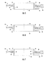
- the insert 42 may be generally annular in shape. However, it should be known by one of ordinary skill in the art that the insert 42 may be of any size or shape that is complementary to the one or more dilution holes 32 and/or the passages 34. As shown in Figs. 3-9 , the insert 42 generally includes an inner surface 44 axially separated from an outer surface 46. As shown in Figs. 4-9 , the insert 42 also includes a bottom end 48 radially separated from a top end 50.
- a projection 52 extends at least partially circumferentially around the insert outer surface 46. As shown, the projection 52 extends generally axially away from the insert outer surface 46 and extends partially radially between the insert bottom end 48 and the insert top end 50. In particular embodiments, the projection 52 may be welded and/or brazed to the insert outer surface 46. In the alternative, the projection 52 and the insert 42 may be machined from a single piece of material. In this manner, the projection 42 may be said to be integral with the insert.
- the projection 52 may at least partially define a projection mating surface 54 that at least partially circumferentially surrounds the projection 52.
- the projection mating surface 54 may be any shape that is complementary to the liner mating surface 40.
- the projection mating surface 54 may be shaped so as to provide a butt joint 56 between the liner mating surface 40 and the projection mating surface 54.
- the liner mating surface 40 and the projection mating surface 54 may be generally parallel.
- the liner mating surface 40 and the projection mating surface 54 may be chamfered.
- the liner mating surface 40 may diverge radially outward through the dilution hole 32 from the liner inner surface 36, and the projection mating surface 54 may diverge radially outward complementary to the liner mating surface 40.
- the liner mating surface 40 may converge inward through the dilution hole 32 and/or the passages 34 from the liner inner surface 36 to the liner outer surface 38, and the projection mating surface 54 may diverge inward complementary to the liner mating surface 40.
- a butt weld may join the insert 42 to the liner 20, thereby allowing for a full penetration weld between the liner mating surface 40 and the projection mating surface 54.
- the probability of cracking the joint during operation of the combustor 10 may be reduced, thus resulting in increased mechanical life of the liner and/or the combustor.
- the projection 52 may at least partially define a groove 58 that extends at least partially circumferentially around the projection mating surface 54.
- the groove 58 may be of any depth and/or width.
- a braze ring 60 may be inserted into the groove 58.
- the liner mating surface 40 and the projection mating surface 54 may be shaped so as to provide a butt joint 56 between the liner mating surface 40 and the projection mating surface 54.
- the liner mating surface 40 and the projection mating surface 54 may be generally parallel.
- the liner mating surface 40 and the projection mating surface 54 may be chamfered.
- the liner mating surface 40 may diverge inward from the liner inner surface 3 towards the liner outer surface 36, and the projection mating surface 54 may diverge complementary to the liner mating surface 40.
- the liner mating surface 40 may converge from the liner inner surface 34 towards the liner outer surface 36, and the projection mating surface 54 may converge complementary to the liner mating surface 40.
- a brazed butt joint 62 may connect the projection mating surface 40 to the liner mating surface 54, thereby allowing for a full penetration joint between the liner mating surface 40 and the projection mating surface 54.
- the probability of cracking the joint during operation of the combustor may be reduced, thus resulting in increased mechanical life of the liner.
- the various embodiments shown and described with respect to Figs. 4-9 may also provide a method for repairing the combustor 10.
- the method may include removing a first insert 42 from at least one of the one or more dilution holes 32 and/or the one or more passages 34, enlarging the diameter of the dilution hole 32 and/or the passages 34, inserting a second insert 42 that includes the projection 52 and the projection mating surface 54, and joining the projection mating surface 54 to a complementary liner mating surface 40 so as to provide a butt joint 56 therebetween.
- the method may further include butt welding the projection mating surface 54 to the complementary liner mating surface 40.
- the method may include inserting the braze ring 60 into the groove 58 at least partially defined in the projection 52 and brazing the projection mating surface 54 to the complementary liner mating surface 40.
- the method may also include chamfering the liner 20 dilution hole 32.
- the method may include chamfering the liner 20 dilution hole 32 radially outward from the liner inner surface 36.
- the method may further include chamfering the liner 20 dilution hole 32 radially inward from the liner inner surface 36.
- Figs. 4-9 may also provide a method for assembling the combustor 10.
- the method may include inserting the insert 42 that includes the projection 52 and the projection mating surface 54 into the liner 20 dilution hole 32 and/or into at least one of passages 34 and joining the projection mating surface 54 to a complementary liner mating surface 40 so as to provide a butt joint 56 therebetween.
Landscapes
- Engineering & Computer Science (AREA)
- Chemical & Material Sciences (AREA)
- Combustion & Propulsion (AREA)
- Mechanical Engineering (AREA)
- General Engineering & Computer Science (AREA)
- Turbine Rotor Nozzle Sealing (AREA)
- Gas Burners (AREA)
Applications Claiming Priority (1)
| Application Number | Priority Date | Filing Date | Title |
|---|---|---|---|
| US13/456,602 US20130283806A1 (en) | 2012-04-26 | 2012-04-26 | Combustor and a method for repairing the combustor |
Publications (1)
| Publication Number | Publication Date |
|---|---|
| EP2657606A2 true EP2657606A2 (fr) | 2013-10-30 |
Family
ID=48190244
Family Applications (1)
| Application Number | Title | Priority Date | Filing Date |
|---|---|---|---|
| EP13165435.2A Withdrawn EP2657606A2 (fr) | 2012-04-26 | 2013-04-25 | Chambre de combustion et procédé permettant de réparer la chambre de combustion |
Country Status (5)
| Country | Link |
|---|---|
| US (1) | US20130283806A1 (fr) |
| EP (1) | EP2657606A2 (fr) |
| JP (1) | JP2013228196A (fr) |
| CN (1) | CN103375798A (fr) |
| RU (1) | RU2013119152A (fr) |
Cited By (1)
| Publication number | Priority date | Publication date | Assignee | Title |
|---|---|---|---|---|
| FR3022613A1 (fr) * | 2014-06-24 | 2015-12-25 | Turbomeca | Bossage pour chambre de combustion. |
Families Citing this family (7)
| Publication number | Priority date | Publication date | Assignee | Title |
|---|---|---|---|---|
| US20130318986A1 (en) * | 2012-06-05 | 2013-12-05 | General Electric Company | Impingement cooled combustor |
| DE102012022259A1 (de) * | 2012-11-13 | 2014-05-28 | Rolls-Royce Deutschland Ltd & Co Kg | Brennkammerschindel einer Gasturbine sowie Verfahren zu deren Herstellung |
| US10151486B2 (en) * | 2014-01-03 | 2018-12-11 | United Technologies Corporation | Cooled grommet for a combustor wall assembly |
| US9278386B1 (en) | 2014-09-04 | 2016-03-08 | General Electric Company | Hole reducing tool |
| US10337736B2 (en) * | 2015-07-24 | 2019-07-02 | Pratt & Whitney Canada Corp. | Gas turbine engine combustor and method of forming same |
| US11371703B2 (en) * | 2018-01-12 | 2022-06-28 | Raytheon Technologies Corporation | Apparatus and method for mitigating particulate accumulation on a component of a gas turbine |
| US11698192B2 (en) * | 2021-04-06 | 2023-07-11 | Raytheon Technologies Corporation | CMC combustor panel attachment arrangement |
Family Cites Families (12)
| Publication number | Priority date | Publication date | Assignee | Title |
|---|---|---|---|---|
| GB1240009A (en) * | 1968-07-27 | 1971-07-21 | Leyland Gas Turbines Ltd | Flame tube |
| US3981142A (en) * | 1974-04-01 | 1976-09-21 | General Motors Corporation | Ceramic combustion liner |
| US4132066A (en) * | 1977-09-23 | 1979-01-02 | United Technologies Corporation | Combustor liner for gas turbine engine |
| GB2017827B (en) * | 1978-04-04 | 1983-02-02 | Gen Electric | Combustor liner cooling |
| US4700544A (en) * | 1985-01-07 | 1987-10-20 | United Technologies Corporation | Combustors |
| US4887432A (en) * | 1988-10-07 | 1989-12-19 | Westinghouse Electric Corp. | Gas turbine combustion chamber with air scoops |
| FR2674317B1 (fr) * | 1991-03-20 | 1993-05-28 | Snecma | Chambre de combustion de turbomachine comportant un reglage du debit de comburant. |
| US6351949B1 (en) * | 1999-09-03 | 2002-03-05 | Allison Advanced Development Company | Interchangeable combustor chute |
| US6484505B1 (en) * | 2000-02-25 | 2002-11-26 | General Electric Company | Combustor liner cooling thimbles and related method |
| US8281600B2 (en) * | 2007-01-09 | 2012-10-09 | General Electric Company | Thimble, sleeve, and method for cooling a combustor assembly |
| US8448443B2 (en) * | 2007-10-11 | 2013-05-28 | General Electric Company | Combustion liner thimble insert and related method |
| US8397511B2 (en) * | 2009-05-19 | 2013-03-19 | General Electric Company | System and method for cooling a wall of a gas turbine combustor |
-
2012
- 2012-04-26 US US13/456,602 patent/US20130283806A1/en not_active Abandoned
-
2013
- 2013-04-24 JP JP2013090842A patent/JP2013228196A/ja active Pending
- 2013-04-25 EP EP13165435.2A patent/EP2657606A2/fr not_active Withdrawn
- 2013-04-25 RU RU2013119152/06A patent/RU2013119152A/ru not_active Application Discontinuation
- 2013-04-26 CN CN2013101504379A patent/CN103375798A/zh active Pending
Non-Patent Citations (1)
| Title |
|---|
| None |
Cited By (3)
| Publication number | Priority date | Publication date | Assignee | Title |
|---|---|---|---|---|
| FR3022613A1 (fr) * | 2014-06-24 | 2015-12-25 | Turbomeca | Bossage pour chambre de combustion. |
| WO2015197954A1 (fr) * | 2014-06-24 | 2015-12-30 | Turbomeca | Ensemble pour chambre de combustion de turbomachine comprenant un bossage et un élément annulaire |
| US10941943B2 (en) | 2014-06-24 | 2021-03-09 | Safran Helicopter Engines | Assembly for turbomachine combustion chamber comprising a boss and an annular element |
Also Published As
| Publication number | Publication date |
|---|---|
| RU2013119152A (ru) | 2014-10-27 |
| CN103375798A (zh) | 2013-10-30 |
| JP2013228196A (ja) | 2013-11-07 |
| US20130283806A1 (en) | 2013-10-31 |
Similar Documents
| Publication | Publication Date | Title |
|---|---|---|
| EP2657606A2 (fr) | Chambre de combustion et procédé permettant de réparer la chambre de combustion | |
| EP2899466B1 (fr) | Procédé de réparation d'un injecteur de carburant à faisceau tubulaire | |
| EP2636952A2 (fr) | Buse de combustible et chambre de combustion pour turbine à gaz | |
| US9423134B2 (en) | Bundled tube fuel injector with a multi-configuration tube tip | |
| US20110081239A1 (en) | Fabricated static vane ring | |
| US20120117976A1 (en) | Apparatus and method for igniting a combustor | |
| US20160116168A1 (en) | Robust insulated fuel injector for a gas turbine engine | |
| EP3377819B1 (fr) | Procédé de reconditionnement d'ensembles de buse de combustible | |
| JP7202090B2 (ja) | 一体型燃料ノズル接続部 | |
| US20070258808A1 (en) | Combustor spring clip seal system | |
| US9032735B2 (en) | Combustor and a method for assembling the combustor | |
| US20160091201A1 (en) | Fuel nozzle | |
| US9423136B2 (en) | Bundled tube fuel injector aft plate retention | |
| EP2574847A2 (fr) | Chemise de combustion pour moteur à turbine | |
| CN102620318A (zh) | 燃烧器及维修燃烧器的方法 | |
| EP2631543A2 (fr) | Chambre de combustion et procédé pour purger une chambre de combustion | |
| EP3078914A1 (fr) | Chambre de combustion annulaire pour un moteur à turbine à gaz | |
| EP4524470A1 (fr) | Moteur à turbine à gaz et injecteur de carburant associé | |
| CN103216335B (zh) | 一种制作燃料喷嘴组件的工艺 | |
| US9016064B2 (en) | Combustor | |
| EP2532966A2 (fr) | Buse de combustion et procédé pour modifier une telle buse |
Legal Events
| Date | Code | Title | Description |
|---|---|---|---|
| PUAI | Public reference made under article 153(3) epc to a published international application that has entered the european phase |
Free format text: ORIGINAL CODE: 0009012 |
|
| AK | Designated contracting states |
Kind code of ref document: A2 Designated state(s): AL AT BE BG CH CY CZ DE DK EE ES FI FR GB GR HR HU IE IS IT LI LT LU LV MC MK MT NL NO PL PT RO RS SE SI SK SM TR |
|
| AX | Request for extension of the european patent |
Extension state: BA ME |
|
| STAA | Information on the status of an ep patent application or granted ep patent |
Free format text: STATUS: THE APPLICATION IS DEEMED TO BE WITHDRAWN |
|
| 18D | Application deemed to be withdrawn |
Effective date: 20161101 |