EP2657632A2 - Kühlschrank und Montageverfahren einer Griffanordnung - Google Patents
Kühlschrank und Montageverfahren einer Griffanordnung Download PDFInfo
- Publication number
- EP2657632A2 EP2657632A2 EP13163837.1A EP13163837A EP2657632A2 EP 2657632 A2 EP2657632 A2 EP 2657632A2 EP 13163837 A EP13163837 A EP 13163837A EP 2657632 A2 EP2657632 A2 EP 2657632A2
- Authority
- EP
- European Patent Office
- Prior art keywords
- handle
- connector
- fixing unit
- door
- fastening
- Prior art date
- Legal status (The legal status is an assumption and is not a legal conclusion. Google has not performed a legal analysis and makes no representation as to the accuracy of the status listed.)
- Granted
Links
Images


Classifications
-
- F—MECHANICAL ENGINEERING; LIGHTING; HEATING; WEAPONS; BLASTING
- F25—REFRIGERATION OR COOLING; COMBINED HEATING AND REFRIGERATION SYSTEMS; HEAT PUMP SYSTEMS; MANUFACTURE OR STORAGE OF ICE; LIQUEFACTION SOLIDIFICATION OF GASES
- F25D—REFRIGERATORS; COLD ROOMS; ICE-BOXES; COOLING OR FREEZING APPARATUS NOT OTHERWISE PROVIDED FOR
- F25D23/00—General constructional features
- F25D23/02—Doors; Covers
- F25D23/028—Details
-
- F—MECHANICAL ENGINEERING; LIGHTING; HEATING; WEAPONS; BLASTING
- F25—REFRIGERATION OR COOLING; COMBINED HEATING AND REFRIGERATION SYSTEMS; HEAT PUMP SYSTEMS; MANUFACTURE OR STORAGE OF ICE; LIQUEFACTION SOLIDIFICATION OF GASES
- F25D—REFRIGERATORS; COLD ROOMS; ICE-BOXES; COOLING OR FREEZING APPARATUS NOT OTHERWISE PROVIDED FOR
- F25D23/00—General constructional features
- F25D23/02—Doors; Covers
-
- Y—GENERAL TAGGING OF NEW TECHNOLOGICAL DEVELOPMENTS; GENERAL TAGGING OF CROSS-SECTIONAL TECHNOLOGIES SPANNING OVER SEVERAL SECTIONS OF THE IPC; TECHNICAL SUBJECTS COVERED BY FORMER USPC CROSS-REFERENCE ART COLLECTIONS [XRACs] AND DIGESTS
- Y10—TECHNICAL SUBJECTS COVERED BY FORMER USPC
- Y10T—TECHNICAL SUBJECTS COVERED BY FORMER US CLASSIFICATION
- Y10T29/00—Metal working
- Y10T29/49—Method of mechanical manufacture
- Y10T29/4935—Heat exchanger or boiler making
- Y10T29/49359—Cooling apparatus making, e.g., air conditioner, refrigerator
-
- Y—GENERAL TAGGING OF NEW TECHNOLOGICAL DEVELOPMENTS; GENERAL TAGGING OF CROSS-SECTIONAL TECHNOLOGIES SPANNING OVER SEVERAL SECTIONS OF THE IPC; TECHNICAL SUBJECTS COVERED BY FORMER USPC CROSS-REFERENCE ART COLLECTIONS [XRACs] AND DIGESTS
- Y10—TECHNICAL SUBJECTS COVERED BY FORMER USPC
- Y10T—TECHNICAL SUBJECTS COVERED BY FORMER US CLASSIFICATION
- Y10T29/00—Metal working
- Y10T29/49—Method of mechanical manufacture
- Y10T29/49826—Assembling or joining
- Y10T29/49947—Assembling or joining by applying separate fastener
- Y10T29/49948—Multipart cooperating fastener [e.g., bolt and nut]
Definitions
- Embodiments relate to a refrigerator and a handle assembly method thereof.
- a refrigerator in general, includes storage chambers and a cold air supply apparatus supplying cold air to the storage chambers, and thus stores foods in a fresh state.
- the storage chambers are divided into a refrigerating chamber and a freezing chamber so as to store food in a refrigerated state or in a frozen state according to states of the food to be stored.
- the front surfaces of such storage chambers of the refrigerator are opened, and the opened front surfaces are opened and closed by doors rotatably combined with a main body of the refrigerator or drawers slidably combined with the main body.
- a handle facilitating user manipulation is mounted on the door or the drawer.
- the handle is assembled in a manner that both ends of the handle are fastened to handle inner structures and mounts of the door or the drawer by separate screws.
- the handle is assembled in a sliding manner without fastening to the handle inner structures and mounts of the door or the drawer by separate screws.
- both ends of the handle are fastened by screws, both ends of the handle need to be fastened by the screws and thus convenience in assembly is lowered.
- both ends of the handles are provided with screw holes and thus external appearance of the refrigerator is poor.
- both ends of the handle are fastened in the sliding manner, fastening using screws is omitted and thus convenience in assembly is high.
- the handle when the handle is assembled with a small force, the handle may be separated from the door or the drawer or a gap may be generated between the handle and the door or the drawer.
- a refrigerator which reduces the number of fastening units to increase convenience in assembly of a handle and reduces generation of scratches on the surface of a door or a drawer in assembly of the handle, and a handle assembly method thereof.
- a refrigerator which includes a main body, doors rotatably combined with the main body and opening and closing the main body, a handle combined with each door to open and close each door, a first handle fixing unit assembled with each door to fix the handle to each door and provided with an inclined part fixed to one end of the handle by a fastening unit, a second handle fixing unit assembled with each door to fix the handle to each door and combined with the other end of the handle, a first connector assembled with one end of the handle and fastened to the first handle fixing unit by the fastening unit to combine the handle with each door, and a second connector assembled with the other end of the handle and combined with the second handle fixing unit by sliding the second handle fixing unit and the second connector together to combine the handle with each door.
- the handle may have a hollow cylindrical shape, be formed in an arc shape in which the central part of the handle is protruded farther forward than both ends of the handle and be combined with the front surface of each door, and the first connector and the second connector may be accommodated in both ends of the handle and are assembled with the handle.
- a fastening part to which the first connector or the second connector is fastened, and guide rails guiding the first connector or the second connector may be provided at each of both ends of the handle.
- the first handle fixing unit may include a combining part combined with each door and an insertion part protruded from the front surface of the combining part and inserted into the first connector, and the insertion part includes a body part and a head part protruded from the front surface of the body part so as to have a greater diameter than the body part.
- the inclined part may be inclined such that the diameter thereof is gradually decreased between the head part and the body part in a direction from the lower portion of the head part toward the combining part, a first fastening hole and a second fastening hole may be provided on the first connector and the handle at positions corresponding to the inclined part, and the handle may be fixed to the first handle fixing unit by allowing the fastening unit inserted into the first fastening hole and the second fastening hole to move from a portion of the inclined part having a large diameter to a portion of the inclined part having a small diameter along the inclined surface of the inclined part.
- the first connector may include an insertion recess into which the insertion part is inserted, a fastening groove fastened to the fastening part by a fastening member, and guide parts guided by the guide rails, and the first fastening hole may be formed through one side surface of the insertion recess.
- the second handle fixing unit may include a combining part combined with each door and an insertion part protruded from the front surface of the combining part and inserted into the second connector, and the insertion part may include a body part and a head part protruded from the front surface of the body part so as to have a greater diameter than the body part.
- the second connector may include an insertion recess having a size corresponding to the diameter of the head part so that the insertion part may be inserted into the insertion recess, and a guide groove having a size corresponding to the diameter of the body part and guiding movement of the body part.
- the second connector may further include a fastening groove fastened to the fastening part of the handle by a fastening member, and guide parts guided by the guide rails.
- a refrigerator which includes a main body, drawers slidably combined with the main body and opening and closing the main body, a handle combined with each drawer to open and close each drawer, a first handle fixing unit assembled with each drawer to fix the handle to each drawer and provided with an inclined part fixed to one end of the handle by a fastening unit, a second handle fixing unit assembled with each drawer to fix the handle to each drawer and combined with the other end of the handle, a first connector assembled with one end of the handle and fastened to the first handle fixing unit by the fastening unit to combine the handle with each drawer, and a second connector assembled with the other end of the handle and combined with the second handle fixing unit by sliding the second handle fixing unit and the second connector together to combine the handle with each drawer.
- the handle may have a hollow cylindrical shape, be formed in an arc shape in which the central part of the handle is protruded farther forward than both ends of the handle and be combined with the front surface of each drawer, and the first connector and the second connector may be accommodated in both ends of the handle and are assembled with the handle.
- a fastening part to which the first connector or the second connector is fastened, and guide rails guiding the first connector or the second connector may be provided at each of both ends of the handle.
- the first handle fixing unit may include a combining part combined with each drawer and an insertion part protruded from the front surface of the combining part and inserted into the first connector, and the insertion part may include a body part and a head part protruded from the front surface of the body part so as to have a greater diameter than the body part.
- the inclined part may be inclined such that the diameter thereof is gradually decreased between the head part and the body part in a direction from the lower portion of the head part toward the combining part, a first fastening hole and a second fastening hole may be provided on the first connector and the handle at positions corresponding to the inclined part, and the handle may be fixed to the first handle fixing unit by allowing the fastening unit inserted into the first fastening hole and the second fastening hole to move from a portion of the inclined part having a large diameter to a portion of the inclined part having a small diameter along the inclined surface of the inclined part.
- the first connector may include an insertion recess into which the insertion part is inserted, a fastening groove fastened to the fastening part by a fastening member, and guide parts guided by the guide rails, and the first fastening hole may be formed through one side surface of the insertion recess.
- the second handle fixing unit may include a combining part combined with each drawer and an insertion part protruded from the front surface of the combining part and inserted into the second connector, and the insertion part may include a body part and a head part protruded from the front surface of the body part so as to have a greater diameter than the body part.
- the second connector may include an insertion recess having a size corresponding to the diameter of the head part so that the insertion part may be inserted into the insertion recess, and a guide groove having a size corresponding to the diameter of the body part and guiding movement of the body part.
- the second connector may further include a fastening groove fastened to the fastening part of the handle by a fastening member, and guide parts guided by the guide rails.
- a handle assembly method of a refrigerator which has a main body, doors rotatably combined with the main body and opening and closing the main body, and a handle combined with each door to open and close each door, includes assembling a first handle fixing unit and a second handle fixing unit with positions of each door corresponding to both ends of the handle, assembling a first connector and a second connector with both ends of the handle, inserting a body part of the second handle fixing unit into a guide groove of the second connector by slidably moving the handle toward the assembly position of the second handle fixing unit with each door, after insertion of an insertion part of the second handle fixing unit into an insertion recess of the second connector assembled with one end of the handle, and inserting an insertion part of the first handle fixing unit into an insertion recess of the first connector assembled with the other end of the handle, and then combining the handle with the first handle fixing unit by a fastening unit.
- interference between the other end of the handle and the first handle fixing unit may be prevented by inserting the insertion part of the second handle fixing unit into the insertion recess of the second connector, after drawing of the upper portion of the handle in the forward direction.
- a refrigerator in accordance with an embodiment includes a main body 10, doors 20 rotatably combined with the main body 10 and opening and closing the main body 10, a handle 30 combined with each door 20 to open and close each door 20, a first handle fixing unit 40 and a second handle fixing unit 50 assembled with each door 20 and combined with the handle 30, a first connector 60 assembled with one end of the handle 30 and combined with the first handle fixing unit 40, and a second connector 70 assembled with the other end of the handle 30 and combined with the second handle fixing unit 50.
- the main body 10 includes an inner case (not shown) forming storage chambers (not shown) and an outer case (not shown) forming the external appearance of the main body 10, and the doors 20 and a drawer 80 are combined with the main body 10 so as to open and close the storage chambers, front surfaces of which are opened.
- the doors 20 are rotatably combined with the main body 10 and open and close the corresponding storage chamber, and the drawer 80 is slidably combined with the main body 10 and opens and close the corresponding storage chamber.
- the handle 30 gripped by user so as to easily open and close the doors 20 and the drawer 80 is combined with the doors 20 and the drawer 80.
- the handle 30 has a hollow cylindrical shape, is formed in an arc shape in which the central part of the handle 30 is protruded farther forward than both ends of the handle 30 so as to allow a user to easily grip the handle 30, and is combined with the front surfaces of the doors 20 and the drawer 80.
- the handle 30 includes a second fastening hole 31 into which a fastening unit B1 is inserted so as to fix the first connector 60 or the second connector 70 combined with the handle 30 to the first handle fixing unit 40 or the second handle fixing unit 50, fastening parts 33 fastened to the first connector 60 and the second connector 70, and guide rails 35 guiding the first connector 60 and the second connector 70 so that the first and second connectors 60 and 70 are easily accommodated within the handle 30.
- the first connector 60 and the second connector 70 to combine the handle 30 with the door 20 or the drawer 80 are combined with the vacant inner space of the handle 30, and a detailed description thereof will be described later.
- the first handle fixing unit 40 and the second handle fixing unit 50 are assembled with the door 20.
- the first handle fixing unit 40 is assembled with the door 20 and combined with the upper portion of the handle 30.
- the first handle fixing unit 40 includes a combining part 41 combined with the door 20, and an insertion part 43 protruded from the front surface of the combining part 41 and inserted into the first connector 60.
- the insertion part 43 includes a body part 43a connected to the combining part 41 and protruded from the front surface of the combining part 41, a head part 43b protruded from the front surface of the body part 43a so as to have a greater diameter than the body part 43a, and an inclined part 43c inclined such that the diameter thereof is gradually decreased in a direction from the lower portion of the head part 43b toward the combining part 41.
- a first fastening hole 61 and the second fastening hole 31 are provided on the first connector 60 and the upper portion of the handle 30 combined with the first handle fixing unit 40 at positions corresponding to the inclined part 43c.
- the front end of the fastening unit B1 contacting a portion of the inclined part 43c having a large diameter moves to a portion of the inclined part 43c having a small diameter along the inclined surface of the inclined part 43c, thus fixing the first connector 60 combined with the handle 30 to the first handle fixing unit 40.
- the first handle fixing unit 40 and the handle 30 are combined by assembling the first connector 60 with the upper portion of the handle 30, inserting the insertion part 43 of the first handle fixing unit 40 into an insertion recess 63 of the first connector 60, and fixing the front end of the fastening unit B1 to the inclined part 43c of the first handle fixing unit 40 by inserting the fastening unit B1 into the first fastening hole 61 provided on the first connector 60 and the second fastening hole 31 provided on the upper portion of the handle 30.
- the second handle fixing unit 50 is assembled with the door 20 and combined with the lower portion of the handle 30.
- the second handle fixing unit 50 includes a combining part 51 combined with the door 20, and an insertion part 53 protruded from the front surface of the combining part 51 and inserted into the second connector 70.
- the insertion part 53 includes a body part 53a connected to the combining part 51 and protruded from the front surface of the combining part 51, and a head part 53b protruded from the front surface of the body part 53a so as to have a greater diameter than the body part 53a.
- the second handle fixing unit 50 and the handle 30 are combined by assembling the second connector 70 with the lower portion of the handle 30, inserting the insertion part 53 of the second handle fixing unit 50 into an insertion recess 71 of the second connector 70, and slidably moving the body part 53a along a guide groove 73 of the second connector 70 formed so as to have a size corresponding to the diameter of the body part 53a,
- the first connector 60 is combined with the upper portion of the handle 30, and is combined with the first handle fixing unit 40 assembled with the door 20 by the fastening unit B1.
- the first connector 60 which is accommodated in the vacant inner space of the handle 30 includes the insertion recess 63 into which the insertion part 43 of the first handle fixing unit 40 is inserted, the first fastening hole 61 provided at a position corresponding to the inclined part 43c provided on the first handle fixing unit 40, a fastening groove 65 fastened to the fastening part 33 of the handle 30 by a fastening member B2, and guide parts 67 guided by the guide rails 35 of the handle 30 so that the first connector 60 may be easily inserted into the handle 30.
- the handle 30 and the first connector 60 are combined by inserting the first connector 60 into the vacant inner space of the handle 30 so that the fastening part 33 of the handle 30 and the fastening groove 65 of the first connector 60 coincide with each other.
- the guide parts 67 of the first connector 60 move along the guide rails 35 of the handle 30, thereby facilitating insertion of the first connector 60 into the vacant inner space of the handle 30.
- the first connector 60 When the first connector 60 is inserted into the vacant inner space of the handle 30 so that the fastening part 33 of the handle 30 and the fastening groove 65 of the first connector 60 coincide with each other, the first connector 60 is combined with the handle 30 through fastening between the fastening groove 65 and the fastening part 33 using the fastening member B2.
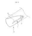
- the first connector 60 assembled with the upper portion of the handle 30 and the first handle fixing unit 40 assembled with the door 20 are combined by fixing the front end of the fastening unit B1 to the inclined part 43c of the first handle fixing unit 40, as shown in FIG. 3 , by inserting the fastening unit B1 into the first fastening hole 61 formed through the side surface of the insertion recess 63 of the first connector 60 and the second fastening hole 31 provided on the upper portion of the handle 30.
- the second connector 70 is combined with the lower portion of the handle 30, and is combined with the second handle fixing unit 60 assembled with the door 20 in a sliding manner.
- the second connector 70 which is accommodated in the vacant inner space of the handle 30 includes the insertion recess 71 having a size corresponding to the diameter of the head part 53b of the second handle fixing unit 50 so that the insertion part 53 of the second handle fixing unit 50 may be inserted into the insertion groove 71, the guide groove 73 having a size corresponding to the diameter of the body part 53a of the second handle fixing unit 50 and guiding movement of the body part 53a, a fastening groove 75 fastened to the fastening part 33 of the handle 30 by a fastening member B2, and guide parts 77 guided by the guide rails 35 of the handle 30 so that the second connector 70 may be easily inserted into the handle 30.
- the handle 30 and the second connector 70 are combined by inserting the second connector 70 into the vacant inner space of the handle 30 so that the fastening part 33 of the handle 30 and the fastening groove 75 of the second connector 70 coincide with each other.
- the guide parts 77 of the second connector 70 move along the guide rails 35 of the handle 30, thereby facilitating insertion of the second connector 70 into the vacant space of the handle 30.
- the second connector 70 When the second connector 70 is inserted into the vacant inner space of the handle 30 so that the fastening part 33 of the handle 30 and the fastening groove 75 of the second connector 70 coincide with each other, the second connector 70 is combined with the handle 30 through fastening between the fastening groove 75 and the fastening part 33 using the fastening member B2.
- the second connector 70 assembled with the lower portion of the handle 30 and the second handle fixing unit 50 assembled with the door 20 are combined in the sliding manner by moving the handle 30 in the downward direction so that the body part 53a of the second handle fixing unit 50 is guided along the guide groove 73 of the second connector 70, after insertion of the insertion part 53 of the second handle fixing unit 50 into the insertion recess 71 of the second connector 70.
- the first handle fixing unit 40 may be assembled with the door 20 and combined with the lower portion of the handle 30, and the second handle fixing unit 50 may be assembled with the door 20 and combined with the upper portion of the handle 30.
- the first connector 60 is assembled with the lower portion of the handle 30, and is then combined with the first handle fixing unit 40 by the fastening unit B1.
- Combining of the lower portion of the handle 30 with the first handle fixing unit 40 by combining the first connector 60 and the first handle fixing unit 40 by the fastening unit B1 is the same as the combining manner of the upper portion of the handle 30 with the first handle fixing unit 40.
- the second connector 70 is assembled with the upper portion of the handle 30, and is then combined with the second handle fixing unit 50 in the sliding manner.
- Combining of the upper portion of the handle 30 with the second handle fixing unit 50 by combining the second connector 70 and the second handle fixing unit 50 in the sliding manner is the same as combining of the lower portion of the handle 30 with the second handle fixing unit 50.
- the first handle fixing unit 40 may be assembled with the drawer 80 and combined with the right portion of the handle 30, and the second handle fixing unit 50 may be assembled with the drawer 80 and combined with the left portion of the handle 30.
- the first connector 60 is assembled with the right portion of the handle 30, and is then combined with the first handle fixing unit 40 by the fastening unit B1.
- Combining of the right portion of the handle 30 with the first handle fixing unit 40 by combining the first connector 60 and the first handle fixing unit 40 by the fastening unit B1 is the same as combining of the upper or lower portion of the handle 30 with the first handle fixing unit 40.
- the second connector 70 is assembled with the left portion of the handle 30, and is then combined with the second handle fixing unit 50 in the sliding manner.
- Combining of the left portion of the handle 30 with the second handle fixing unit 50 by combining the second connector 70 and the second handle fixing unit 50 in the sliding manner is the same as combining of the upper or lower portion of the handle 30 with the second handle fixing unit 50.
- the first handle fixing unit 40 may be assembled with the drawer 80 and combined with the left portion of the handle 30, and the second handle fixing unit 50 may be assembled with the drawer 80 and combined with the right portion of the handle 30.
- the first connector 60 is assembled with the left portion of the handle 30, and is then combined with the first handle fixing unit 40 by the fastening unit B1.
- Combining of the left portion of the handle 30 with the first handle fixing unit 40 by combining the first connector 60 and the first handle fixing unit 40 by the fastening unit 81 is the same as combining of the right portion of the handle 30 with the first handle fixing unit 40.
- the second connector 70 is assembled with the right portion of the handle 30, and is then combined with the second handle fixing unit 50 in the sliding manner.
- Combining of the right portion of the handle 30 with the second handle fixing unit 50 by combining the second connector 70 and the second handle fixing unit 50 in the sliding manner is the same as combining of the left portion of the handle 30 with the second handle fixing unit 50.
- the first handle fixing unit 40 and the second handle fixing unit 50 are assembled with positions of the door 20 corresponding to the upper and lower portions of the handle 30.
- the first connector 60 and the second connector 70 are assembled with the upper and lower portions of the handle 30.
- Combination between the handle 30 and the first and second connectors 60 and 70 is achieved by fastening the fastening grooves 65 and 75 provided on the first connector 60 and the second connector 70 and the fastening parts 33 of the handle 30 using the fastening members B2 after coincidence between the fastening grooves 65 and 75 and the fastening parts 33.
- the body part 53a of the second handle fixing unit 50 is inserted into the guide groove 73 of the second connector 70 in the sliding manner by moving the handle 30 toward the lower portion of the door 20 with which the second handle fixing unit 50 is assembled, after insertion of the insertion part 53 of the second handle fixing unit 50 into the insertion recess 71 of the second connector 70 assembled with the lower portion of the handle 70, as shown in FIGS. 5 and 6 .
- interference between the upper portion of the handle 30 and the first handle fixing unit 40 is prevented by inserting the insertion part 53 of the second handle fixing unit 50 into the insertion recess 71 of the second connector 70, after drawing of the upper portion of the handle 30 in the forward direction.
- the insertion part 43 of the first handle fixing unit 40 is inserted into the insertion recess 63 of the first connector 60 assembled with the upper portion of the handle 30, as shown in FIGS. 1 to 3 .
- the handle 30 is assembled with the door 20.
- the above-described assembly method may be carried out regardless of the assembly positions. That is, the handle 30 may be assembled with the door 20 or the drawer 80 by combining the second handle fixing unit 50 with the second connector 70 assembled with the handle 30 in the sliding manner, and then combining the first handle fixing unit 40 with the first connector 60 assembled with the handle 30 using the fastening unit B1.
- a refrigerator and a handle assembly method thereof in accordance with an embodiment increase convenience in assembly of a handle and improve the external appearance of the refrigerator.
Landscapes
- Engineering & Computer Science (AREA)
- Chemical & Material Sciences (AREA)
- Combustion & Propulsion (AREA)
- Physics & Mathematics (AREA)
- Mechanical Engineering (AREA)
- Thermal Sciences (AREA)
- General Engineering & Computer Science (AREA)
- Refrigerator Housings (AREA)
Applications Claiming Priority (1)
| Application Number | Priority Date | Filing Date | Title |
|---|---|---|---|
| KR1020120044224A KR101519876B1 (ko) | 2012-04-27 | 2012-04-27 | 냉장고 및 냉장고의 핸들 조립방법 |
Publications (3)
| Publication Number | Publication Date |
|---|---|
| EP2657632A2 true EP2657632A2 (de) | 2013-10-30 |
| EP2657632A3 EP2657632A3 (de) | 2017-01-25 |
| EP2657632B1 EP2657632B1 (de) | 2021-09-22 |
Family
ID=48143460
Family Applications (1)
| Application Number | Title | Priority Date | Filing Date |
|---|---|---|---|
| EP13163837.1A Not-in-force EP2657632B1 (de) | 2012-04-27 | 2013-04-16 | Kühlschrank und Montageverfahren einer Griffanordnung |
Country Status (3)
| Country | Link |
|---|---|
| US (1) | US9009969B2 (de) |
| EP (1) | EP2657632B1 (de) |
| KR (1) | KR101519876B1 (de) |
Cited By (1)
| Publication number | Priority date | Publication date | Assignee | Title |
|---|---|---|---|---|
| US12152406B2 (en) * | 2020-01-10 | 2024-11-26 | Triangle Brass Manufacturing Company, Inc. | Adjustable and configurable standoff |
Families Citing this family (47)
| Publication number | Priority date | Publication date | Assignee | Title |
|---|---|---|---|---|
| US9221210B2 (en) | 2012-04-11 | 2015-12-29 | Whirlpool Corporation | Method to create vacuum insulated cabinets for refrigerators |
| US9140481B2 (en) | 2012-04-02 | 2015-09-22 | Whirlpool Corporation | Folded vacuum insulated structure |
| US9297182B2 (en) * | 2013-05-20 | 2016-03-29 | Electrolux Home Products, Inc. | Handle mounting insert |
| KR102216445B1 (ko) * | 2013-12-06 | 2021-02-17 | 삼성전자주식회사 | 냉장고 |
| CA156344S (en) * | 2013-12-16 | 2015-01-21 | Samsung Electronics Co Ltd | Door handle for oven |
| US10052819B2 (en) | 2014-02-24 | 2018-08-21 | Whirlpool Corporation | Vacuum packaged 3D vacuum insulated door structure and method therefor using a tooling fixture |
| US9689604B2 (en) | 2014-02-24 | 2017-06-27 | Whirlpool Corporation | Multi-section core vacuum insulation panels with hybrid barrier film envelope |
| KR20150112590A (ko) * | 2014-03-28 | 2015-10-07 | 삼성전자주식회사 | 도어 핸들 및 이를 포함하는 냉장고 |
| US9476633B2 (en) | 2015-03-02 | 2016-10-25 | Whirlpool Corporation | 3D vacuum panel and a folding approach to create the 3D vacuum panel from a 2D vacuum panel of non-uniform thickness |
| US10161669B2 (en) | 2015-03-05 | 2018-12-25 | Whirlpool Corporation | Attachment arrangement for vacuum insulated door |
| US9897370B2 (en) | 2015-03-11 | 2018-02-20 | Whirlpool Corporation | Self-contained pantry box system for insertion into an appliance |
| US9441779B1 (en) | 2015-07-01 | 2016-09-13 | Whirlpool Corporation | Split hybrid insulation structure for an appliance |
| US10422573B2 (en) | 2015-12-08 | 2019-09-24 | Whirlpool Corporation | Insulation structure for an appliance having a uniformly mixed multi-component insulation material, and a method for even distribution of material combinations therein |
| US10041724B2 (en) | 2015-12-08 | 2018-08-07 | Whirlpool Corporation | Methods for dispensing and compacting insulation materials into a vacuum sealed structure |
| US11052579B2 (en) | 2015-12-08 | 2021-07-06 | Whirlpool Corporation | Method for preparing a densified insulation material for use in appliance insulated structure |
| US12508751B2 (en) | 2015-12-08 | 2025-12-30 | Whirlpool Corporation | Insulation compaction device and method for forming an insulated structure for an appliance |
| US10222116B2 (en) | 2015-12-08 | 2019-03-05 | Whirlpool Corporation | Method and apparatus for forming a vacuum insulated structure for an appliance having a pressing mechanism incorporated within an insulation delivery system |
| US10429125B2 (en) | 2015-12-08 | 2019-10-01 | Whirlpool Corporation | Insulation structure for an appliance having a uniformly mixed multi-component insulation material, and a method for even distribution of material combinations therein |
| US11994336B2 (en) | 2015-12-09 | 2024-05-28 | Whirlpool Corporation | Vacuum insulated structure with thermal bridge breaker with heat loop |
| US10808987B2 (en) | 2015-12-09 | 2020-10-20 | Whirlpool Corporation | Vacuum insulation structures with multiple insulators |
| US9945151B2 (en) * | 2015-12-10 | 2018-04-17 | Whirlpool Corporation | Invisible handle locking system |
| US10422569B2 (en) | 2015-12-21 | 2019-09-24 | Whirlpool Corporation | Vacuum insulated door construction |
| US10018406B2 (en) | 2015-12-28 | 2018-07-10 | Whirlpool Corporation | Multi-layer gas barrier materials for vacuum insulated structure |
| US10610985B2 (en) | 2015-12-28 | 2020-04-07 | Whirlpool Corporation | Multilayer barrier materials with PVD or plasma coating for vacuum insulated structure |
| US10807298B2 (en) | 2015-12-29 | 2020-10-20 | Whirlpool Corporation | Molded gas barrier parts for vacuum insulated structure |
| US10030905B2 (en) | 2015-12-29 | 2018-07-24 | Whirlpool Corporation | Method of fabricating a vacuum insulated appliance structure |
| US11247369B2 (en) | 2015-12-30 | 2022-02-15 | Whirlpool Corporation | Method of fabricating 3D vacuum insulated refrigerator structure having core material |
| US10712080B2 (en) | 2016-04-15 | 2020-07-14 | Whirlpool Corporation | Vacuum insulated refrigerator cabinet |
| EP3443284B1 (de) | 2016-04-15 | 2020-11-18 | Whirlpool Corporation | Vakuumisolierte kühlstruktur mit dreidimensionalen eigenschaften |
| US11320193B2 (en) | 2016-07-26 | 2022-05-03 | Whirlpool Corporation | Vacuum insulated structure trim breaker |
| WO2018034665A1 (en) | 2016-08-18 | 2018-02-22 | Whirlpool Corporation | Machine compartment for a vacuum insulated structure |
| WO2018101954A1 (en) | 2016-12-02 | 2018-06-07 | Whirlpool Corporation | Hinge support assembly |
| US10352613B2 (en) | 2016-12-05 | 2019-07-16 | Whirlpool Corporation | Pigmented monolayer liner for appliances and methods of making the same |
| US10907888B2 (en) | 2018-06-25 | 2021-02-02 | Whirlpool Corporation | Hybrid pigmented hot stitched color liner system |
| US10907891B2 (en) | 2019-02-18 | 2021-02-02 | Whirlpool Corporation | Trim breaker for a structural cabinet that incorporates a structural glass contact surface |
| US11300351B2 (en) | 2020-01-03 | 2022-04-12 | Whirlpool Corporation | Handle assembly |
| TR202006693A1 (tr) | 2020-04-29 | 2021-11-22 | Arçeli̇k Anoni̇m Şi̇rketi̇ | İyi̇leşti̇ri̇lmi̇ş tutamak i̇çeren soğutucu ci̇haz |
| US12070924B2 (en) | 2020-07-27 | 2024-08-27 | Whirlpool Corporation | Appliance liner having natural fibers |
| KR20220018802A (ko) | 2020-08-07 | 2022-02-15 | 와신 아노다이징 씨오., 엘티디. | 냉장고용 도어핸들 |
| US11248835B1 (en) * | 2020-11-04 | 2022-02-15 | Haier Us Appliance Solutions, Inc. | Quick release handle including lights and sound |
| USD1075464S1 (en) * | 2022-01-28 | 2025-05-20 | Electrolux Home Products, Inc. | Handle for a kitchen appliance |
| USD1074375S1 (en) | 2022-01-28 | 2025-05-13 | Electrolux Home Products, Inc. | Handle for a kitchen appliance |
| KR20230116492A (ko) * | 2022-01-28 | 2023-08-04 | 엘지전자 주식회사 | 냉장고 |
| US12529478B2 (en) | 2023-03-17 | 2026-01-20 | Whirlpool Corporation | Selectively detachable handle assemblies for a door of an oven |
| US20250052480A1 (en) * | 2023-07-10 | 2025-02-13 | Hisense USA Corporation | Refrigerator door handle |
| US12449189B2 (en) | 2024-03-28 | 2025-10-21 | Haier Us Appliance Solutions, Inc. | Handle assembly for an appliance door |
| US20250305756A1 (en) * | 2024-03-28 | 2025-10-02 | Haier Us Appliance Solutions, Inc. | Handle assembly for an appliance door |
Citations (3)
| Publication number | Priority date | Publication date | Assignee | Title |
|---|---|---|---|---|
| US20090007385A1 (en) * | 2007-07-05 | 2009-01-08 | Lg Electronics Inc. | Mounting structure of a door-handle for refrigerator |
| US20100005631A1 (en) * | 2008-07-09 | 2010-01-14 | Whirlpool Corporation | Handle assembly for a domestic appliance |
| CN102003108A (zh) * | 2010-11-19 | 2011-04-06 | 海信科龙电器股份有限公司 | 一种可实现自锁的冰箱拉手装配结构 |
Family Cites Families (11)
| Publication number | Priority date | Publication date | Assignee | Title |
|---|---|---|---|---|
| US3152818A (en) * | 1961-05-08 | 1964-10-13 | Bastian Blessing Co | Bracket hold-down device |
| US4912809A (en) * | 1985-01-11 | 1990-04-03 | Kawneer Company, Inc. | Tandem cone bolt anchor mounting assembly |
| US5797164A (en) * | 1995-11-30 | 1998-08-25 | White Consolidated Industries, Inc. | Dovetail refrigerator door handle lock |
| AU781858B2 (en) * | 1999-12-28 | 2005-06-16 | Lg Electronics Inc. | Door handle installation structure of refrigerator |
| US6609274B2 (en) * | 2001-12-14 | 2003-08-26 | Maytag Corporation | Refrigerator handle assembly |
| US7549713B2 (en) * | 2002-11-18 | 2009-06-23 | Maytag Corporation | Refrigerator handle mounting arrangement |
| KR101042915B1 (ko) | 2004-11-17 | 2011-06-20 | 주식회사 대우일렉트로닉스 | 냉장고 도어 핸들 |
| US7793388B2 (en) * | 2006-07-13 | 2010-09-14 | Maytag Corporation | Handle assembly for a domestic appliance |
| KR20090006517A (ko) | 2007-07-12 | 2009-01-15 | 엘지전자 주식회사 | 냉장고 |
| KR100876689B1 (ko) | 2007-08-27 | 2008-12-31 | 엘지전자 주식회사 | 냉장고 및 냉장고 도어 |
| KR101401896B1 (ko) | 2007-11-20 | 2014-05-29 | 엘지전자 주식회사 | 냉장고 도어핸들 장착구조 |
-
2012
- 2012-04-27 KR KR1020120044224A patent/KR101519876B1/ko active Active
-
2013
- 2013-04-16 EP EP13163837.1A patent/EP2657632B1/de not_active Not-in-force
- 2013-04-25 US US13/870,393 patent/US9009969B2/en active Active
Patent Citations (3)
| Publication number | Priority date | Publication date | Assignee | Title |
|---|---|---|---|---|
| US20090007385A1 (en) * | 2007-07-05 | 2009-01-08 | Lg Electronics Inc. | Mounting structure of a door-handle for refrigerator |
| US20100005631A1 (en) * | 2008-07-09 | 2010-01-14 | Whirlpool Corporation | Handle assembly for a domestic appliance |
| CN102003108A (zh) * | 2010-11-19 | 2011-04-06 | 海信科龙电器股份有限公司 | 一种可实现自锁的冰箱拉手装配结构 |
Cited By (1)
| Publication number | Priority date | Publication date | Assignee | Title |
|---|---|---|---|---|
| US12152406B2 (en) * | 2020-01-10 | 2024-11-26 | Triangle Brass Manufacturing Company, Inc. | Adjustable and configurable standoff |
Also Published As
| Publication number | Publication date |
|---|---|
| US9009969B2 (en) | 2015-04-21 |
| KR101519876B1 (ko) | 2015-05-14 |
| US20130285527A1 (en) | 2013-10-31 |
| EP2657632A3 (de) | 2017-01-25 |
| EP2657632B1 (de) | 2021-09-22 |
| KR20130121212A (ko) | 2013-11-06 |
Similar Documents
| Publication | Publication Date | Title |
|---|---|---|
| US9009969B2 (en) | Refrigerator and handle assembly method thereof | |
| US8814284B2 (en) | Refrigerator | |
| US9534833B2 (en) | Basket for refrigerator | |
| US7765645B2 (en) | Refrigerator | |
| US8328301B2 (en) | Refrigerator | |
| US20110095670A1 (en) | Automatic door closing device of refrigerator and refrigerator having the same | |
| US9689605B2 (en) | Refrigerator | |
| EP3043132B1 (de) | Kühlschrank | |
| KR101644014B1 (ko) | 냉장고 | |
| EP2650629A2 (de) | Schiebevorrichtung und Kühlschrank damit | |
| EP2455693A2 (de) | Kühlschrank und Behälteranordnung dafür | |
| US9459040B2 (en) | Refrigerator | |
| KR20110064720A (ko) | 냉장고 | |
| KR101594177B1 (ko) | 냉장고 및 냉장고의 레일 어셈블리 | |
| KR20090011793A (ko) | 냉장고 | |
| US8459759B2 (en) | Refrigerator and drawer opening/closing apparatus for the same | |
| KR20140125493A (ko) | 수납용기 및 이를 구비하는 냉장고 | |
| US20210239386A1 (en) | Refrigerator | |
| US20130093306A1 (en) | Refrigerator | |
| US8162422B2 (en) | Refrigerator | |
| KR102491969B1 (ko) | 냉장고 | |
| KR20090006517A (ko) | 냉장고 | |
| KR100596526B1 (ko) | 냉장고 | |
| KR20050017603A (ko) | 슬라이딩 레일의 스토퍼 | |
| KR100740504B1 (ko) | 냉장고 |
Legal Events
| Date | Code | Title | Description |
|---|---|---|---|
| PUAI | Public reference made under article 153(3) epc to a published international application that has entered the european phase |
Free format text: ORIGINAL CODE: 0009012 |
|
| AK | Designated contracting states |
Kind code of ref document: A2 Designated state(s): AL AT BE BG CH CY CZ DE DK EE ES FI FR GB GR HR HU IE IS IT LI LT LU LV MC MK MT NL NO PL PT RO RS SE SI SK SM TR |
|
| AX | Request for extension of the european patent |
Extension state: BA ME |
|
| PUAL | Search report despatched |
Free format text: ORIGINAL CODE: 0009013 |
|
| AK | Designated contracting states |
Kind code of ref document: A3 Designated state(s): AL AT BE BG CH CY CZ DE DK EE ES FI FR GB GR HR HU IE IS IT LI LT LU LV MC MK MT NL NO PL PT RO RS SE SI SK SM TR |
|
| AX | Request for extension of the european patent |
Extension state: BA ME |
|
| RIC1 | Information provided on ipc code assigned before grant |
Ipc: F25D 23/02 20060101AFI20161221BHEP Ipc: E05F 11/54 20060101ALI20161221BHEP |
|
| STAA | Information on the status of an ep patent application or granted ep patent |
Free format text: STATUS: REQUEST FOR EXAMINATION WAS MADE |
|
| 17P | Request for examination filed |
Effective date: 20170503 |
|
| RBV | Designated contracting states (corrected) |
Designated state(s): AL AT BE BG CH CY CZ DE DK EE ES FI FR GB GR HR HU IE IS IT LI LT LU LV MC MK MT NL NO PL PT RO RS SE SI SK SM TR |
|
| STAA | Information on the status of an ep patent application or granted ep patent |
Free format text: STATUS: EXAMINATION IS IN PROGRESS |
|
| 17Q | First examination report despatched |
Effective date: 20181008 |
|
| GRAP | Despatch of communication of intention to grant a patent |
Free format text: ORIGINAL CODE: EPIDOSNIGR1 |
|
| STAA | Information on the status of an ep patent application or granted ep patent |
Free format text: STATUS: GRANT OF PATENT IS INTENDED |
|
| INTG | Intention to grant announced |
Effective date: 20201103 |
|
| GRAJ | Information related to disapproval of communication of intention to grant by the applicant or resumption of examination proceedings by the epo deleted |
Free format text: ORIGINAL CODE: EPIDOSDIGR1 |
|
| STAA | Information on the status of an ep patent application or granted ep patent |
Free format text: STATUS: EXAMINATION IS IN PROGRESS |
|
| INTC | Intention to grant announced (deleted) | ||
| GRAP | Despatch of communication of intention to grant a patent |
Free format text: ORIGINAL CODE: EPIDOSNIGR1 |
|
| STAA | Information on the status of an ep patent application or granted ep patent |
Free format text: STATUS: GRANT OF PATENT IS INTENDED |
|
| INTG | Intention to grant announced |
Effective date: 20210421 |
|
| GRAS | Grant fee paid |
Free format text: ORIGINAL CODE: EPIDOSNIGR3 |
|
| GRAA | (expected) grant |
Free format text: ORIGINAL CODE: 0009210 |
|
| STAA | Information on the status of an ep patent application or granted ep patent |
Free format text: STATUS: THE PATENT HAS BEEN GRANTED |
|
| AK | Designated contracting states |
Kind code of ref document: B1 Designated state(s): AL AT BE BG CH CY CZ DE DK EE ES FI FR GB GR HR HU IE IS IT LI LT LU LV MC MK MT NL NO PL PT RO RS SE SI SK SM TR |
|
| REG | Reference to a national code |
Ref country code: GB Ref legal event code: FG4D |
|
| REG | Reference to a national code |
Ref country code: DE Ref legal event code: R096 Ref document number: 602013079321 Country of ref document: DE |
|
| REG | Reference to a national code |
Ref country code: IE Ref legal event code: FG4D |
|
| REG | Reference to a national code |
Ref country code: CH Ref legal event code: EP Ref country code: AT Ref legal event code: REF Ref document number: 1432637 Country of ref document: AT Kind code of ref document: T Effective date: 20211015 |
|
| REG | Reference to a national code |
Ref country code: LT Ref legal event code: MG9D |
|
| REG | Reference to a national code |
Ref country code: NL Ref legal event code: MP Effective date: 20210922 |
|
| PG25 | Lapsed in a contracting state [announced via postgrant information from national office to epo] |
Ref country code: RS Free format text: LAPSE BECAUSE OF FAILURE TO SUBMIT A TRANSLATION OF THE DESCRIPTION OR TO PAY THE FEE WITHIN THE PRESCRIBED TIME-LIMIT Effective date: 20210922 Ref country code: NO Free format text: LAPSE BECAUSE OF FAILURE TO SUBMIT A TRANSLATION OF THE DESCRIPTION OR TO PAY THE FEE WITHIN THE PRESCRIBED TIME-LIMIT Effective date: 20211222 Ref country code: FI Free format text: LAPSE BECAUSE OF FAILURE TO SUBMIT A TRANSLATION OF THE DESCRIPTION OR TO PAY THE FEE WITHIN THE PRESCRIBED TIME-LIMIT Effective date: 20210922 Ref country code: LT Free format text: LAPSE BECAUSE OF FAILURE TO SUBMIT A TRANSLATION OF THE DESCRIPTION OR TO PAY THE FEE WITHIN THE PRESCRIBED TIME-LIMIT Effective date: 20210922 Ref country code: BG Free format text: LAPSE BECAUSE OF FAILURE TO SUBMIT A TRANSLATION OF THE DESCRIPTION OR TO PAY THE FEE WITHIN THE PRESCRIBED TIME-LIMIT Effective date: 20211222 Ref country code: SE Free format text: LAPSE BECAUSE OF FAILURE TO SUBMIT A TRANSLATION OF THE DESCRIPTION OR TO PAY THE FEE WITHIN THE PRESCRIBED TIME-LIMIT Effective date: 20210922 Ref country code: HR Free format text: LAPSE BECAUSE OF FAILURE TO SUBMIT A TRANSLATION OF THE DESCRIPTION OR TO PAY THE FEE WITHIN THE PRESCRIBED TIME-LIMIT Effective date: 20210922 |
|
| REG | Reference to a national code |
Ref country code: AT Ref legal event code: MK05 Ref document number: 1432637 Country of ref document: AT Kind code of ref document: T Effective date: 20210922 |
|
| PG25 | Lapsed in a contracting state [announced via postgrant information from national office to epo] |
Ref country code: LV Free format text: LAPSE BECAUSE OF FAILURE TO SUBMIT A TRANSLATION OF THE DESCRIPTION OR TO PAY THE FEE WITHIN THE PRESCRIBED TIME-LIMIT Effective date: 20210922 Ref country code: GR Free format text: LAPSE BECAUSE OF FAILURE TO SUBMIT A TRANSLATION OF THE DESCRIPTION OR TO PAY THE FEE WITHIN THE PRESCRIBED TIME-LIMIT Effective date: 20211223 |
|
| PG25 | Lapsed in a contracting state [announced via postgrant information from national office to epo] |
Ref country code: AT Free format text: LAPSE BECAUSE OF FAILURE TO SUBMIT A TRANSLATION OF THE DESCRIPTION OR TO PAY THE FEE WITHIN THE PRESCRIBED TIME-LIMIT Effective date: 20210922 |
|
| PG25 | Lapsed in a contracting state [announced via postgrant information from national office to epo] |
Ref country code: IS Free format text: LAPSE BECAUSE OF FAILURE TO SUBMIT A TRANSLATION OF THE DESCRIPTION OR TO PAY THE FEE WITHIN THE PRESCRIBED TIME-LIMIT Effective date: 20220122 Ref country code: SK Free format text: LAPSE BECAUSE OF FAILURE TO SUBMIT A TRANSLATION OF THE DESCRIPTION OR TO PAY THE FEE WITHIN THE PRESCRIBED TIME-LIMIT Effective date: 20210922 Ref country code: RO Free format text: LAPSE BECAUSE OF FAILURE TO SUBMIT A TRANSLATION OF THE DESCRIPTION OR TO PAY THE FEE WITHIN THE PRESCRIBED TIME-LIMIT Effective date: 20210922 Ref country code: PT Free format text: LAPSE BECAUSE OF FAILURE TO SUBMIT A TRANSLATION OF THE DESCRIPTION OR TO PAY THE FEE WITHIN THE PRESCRIBED TIME-LIMIT Effective date: 20220124 Ref country code: PL Free format text: LAPSE BECAUSE OF FAILURE TO SUBMIT A TRANSLATION OF THE DESCRIPTION OR TO PAY THE FEE WITHIN THE PRESCRIBED TIME-LIMIT Effective date: 20210922 Ref country code: NL Free format text: LAPSE BECAUSE OF FAILURE TO SUBMIT A TRANSLATION OF THE DESCRIPTION OR TO PAY THE FEE WITHIN THE PRESCRIBED TIME-LIMIT Effective date: 20210922 Ref country code: ES Free format text: LAPSE BECAUSE OF FAILURE TO SUBMIT A TRANSLATION OF THE DESCRIPTION OR TO PAY THE FEE WITHIN THE PRESCRIBED TIME-LIMIT Effective date: 20210922 Ref country code: EE Free format text: LAPSE BECAUSE OF FAILURE TO SUBMIT A TRANSLATION OF THE DESCRIPTION OR TO PAY THE FEE WITHIN THE PRESCRIBED TIME-LIMIT Effective date: 20210922 Ref country code: CZ Free format text: LAPSE BECAUSE OF FAILURE TO SUBMIT A TRANSLATION OF THE DESCRIPTION OR TO PAY THE FEE WITHIN THE PRESCRIBED TIME-LIMIT Effective date: 20210922 Ref country code: AL Free format text: LAPSE BECAUSE OF FAILURE TO SUBMIT A TRANSLATION OF THE DESCRIPTION OR TO PAY THE FEE WITHIN THE PRESCRIBED TIME-LIMIT Effective date: 20210922 |
|
| REG | Reference to a national code |
Ref country code: DE Ref legal event code: R097 Ref document number: 602013079321 Country of ref document: DE |
|
| PG25 | Lapsed in a contracting state [announced via postgrant information from national office to epo] |
Ref country code: DK Free format text: LAPSE BECAUSE OF FAILURE TO SUBMIT A TRANSLATION OF THE DESCRIPTION OR TO PAY THE FEE WITHIN THE PRESCRIBED TIME-LIMIT Effective date: 20210922 |
|
| PGFP | Annual fee paid to national office [announced via postgrant information from national office to epo] |
Ref country code: DE Payment date: 20220321 Year of fee payment: 10 |
|
| PLBE | No opposition filed within time limit |
Free format text: ORIGINAL CODE: 0009261 |
|
| STAA | Information on the status of an ep patent application or granted ep patent |
Free format text: STATUS: NO OPPOSITION FILED WITHIN TIME LIMIT |
|
| 26N | No opposition filed |
Effective date: 20220623 |
|
| PG25 | Lapsed in a contracting state [announced via postgrant information from national office to epo] |
Ref country code: SI Free format text: LAPSE BECAUSE OF FAILURE TO SUBMIT A TRANSLATION OF THE DESCRIPTION OR TO PAY THE FEE WITHIN THE PRESCRIBED TIME-LIMIT Effective date: 20210922 |
|
| REG | Reference to a national code |
Ref country code: CH Ref legal event code: PL |
|
| GBPC | Gb: european patent ceased through non-payment of renewal fee |
Effective date: 20220416 |
|
| REG | Reference to a national code |
Ref country code: BE Ref legal event code: MM Effective date: 20220430 |
|
| PG25 | Lapsed in a contracting state [announced via postgrant information from national office to epo] |
Ref country code: MC Free format text: LAPSE BECAUSE OF FAILURE TO SUBMIT A TRANSLATION OF THE DESCRIPTION OR TO PAY THE FEE WITHIN THE PRESCRIBED TIME-LIMIT Effective date: 20210922 Ref country code: LU Free format text: LAPSE BECAUSE OF NON-PAYMENT OF DUE FEES Effective date: 20220416 Ref country code: LI Free format text: LAPSE BECAUSE OF NON-PAYMENT OF DUE FEES Effective date: 20220430 Ref country code: IT Free format text: LAPSE BECAUSE OF FAILURE TO SUBMIT A TRANSLATION OF THE DESCRIPTION OR TO PAY THE FEE WITHIN THE PRESCRIBED TIME-LIMIT Effective date: 20210922 Ref country code: GB Free format text: LAPSE BECAUSE OF NON-PAYMENT OF DUE FEES Effective date: 20220416 Ref country code: FR Free format text: LAPSE BECAUSE OF NON-PAYMENT OF DUE FEES Effective date: 20220430 Ref country code: CH Free format text: LAPSE BECAUSE OF NON-PAYMENT OF DUE FEES Effective date: 20220430 |
|
| PG25 | Lapsed in a contracting state [announced via postgrant information from national office to epo] |
Ref country code: BE Free format text: LAPSE BECAUSE OF NON-PAYMENT OF DUE FEES Effective date: 20220430 |
|
| PG25 | Lapsed in a contracting state [announced via postgrant information from national office to epo] |
Ref country code: IE Free format text: LAPSE BECAUSE OF NON-PAYMENT OF DUE FEES Effective date: 20220416 |
|
| REG | Reference to a national code |
Ref country code: DE Ref legal event code: R119 Ref document number: 602013079321 Country of ref document: DE |
|
| PG25 | Lapsed in a contracting state [announced via postgrant information from national office to epo] |
Ref country code: DE Free format text: LAPSE BECAUSE OF NON-PAYMENT OF DUE FEES Effective date: 20231103 |
|
| PG25 | Lapsed in a contracting state [announced via postgrant information from national office to epo] |
Ref country code: HU Free format text: LAPSE BECAUSE OF FAILURE TO SUBMIT A TRANSLATION OF THE DESCRIPTION OR TO PAY THE FEE WITHIN THE PRESCRIBED TIME-LIMIT; INVALID AB INITIO Effective date: 20130416 |
|
| PG25 | Lapsed in a contracting state [announced via postgrant information from national office to epo] |
Ref country code: SM Free format text: LAPSE BECAUSE OF FAILURE TO SUBMIT A TRANSLATION OF THE DESCRIPTION OR TO PAY THE FEE WITHIN THE PRESCRIBED TIME-LIMIT Effective date: 20210922 Ref country code: MK Free format text: LAPSE BECAUSE OF FAILURE TO SUBMIT A TRANSLATION OF THE DESCRIPTION OR TO PAY THE FEE WITHIN THE PRESCRIBED TIME-LIMIT Effective date: 20210922 Ref country code: CY Free format text: LAPSE BECAUSE OF FAILURE TO SUBMIT A TRANSLATION OF THE DESCRIPTION OR TO PAY THE FEE WITHIN THE PRESCRIBED TIME-LIMIT Effective date: 20210922 |
|
| PG25 | Lapsed in a contracting state [announced via postgrant information from national office to epo] |
Ref country code: MT Free format text: LAPSE BECAUSE OF FAILURE TO SUBMIT A TRANSLATION OF THE DESCRIPTION OR TO PAY THE FEE WITHIN THE PRESCRIBED TIME-LIMIT Effective date: 20210922 |
|
| PG25 | Lapsed in a contracting state [announced via postgrant information from national office to epo] |
Ref country code: TR Free format text: LAPSE BECAUSE OF FAILURE TO SUBMIT A TRANSLATION OF THE DESCRIPTION OR TO PAY THE FEE WITHIN THE PRESCRIBED TIME-LIMIT Effective date: 20210922 |