EP2657727B1 - Rideau lumineux - Google Patents
Rideau lumineux Download PDFInfo
- Publication number
- EP2657727B1 EP2657727B1 EP13159321.2A EP13159321A EP2657727B1 EP 2657727 B1 EP2657727 B1 EP 2657727B1 EP 13159321 A EP13159321 A EP 13159321A EP 2657727 B1 EP2657727 B1 EP 2657727B1
- Authority
- EP
- European Patent Office
- Prior art keywords
- housing
- housing body
- light curtain
- cap
- light
- Prior art date
- Legal status (The legal status is an assumption and is not a legal conclusion. Google has not performed a legal analysis and makes no representation as to the accuracy of the status listed.)
- Active
Links
Images

Classifications
-
- G—PHYSICS
- G01—MEASURING; TESTING
- G01V—GEOPHYSICS; GRAVITATIONAL MEASUREMENTS; DETECTING MASSES OR OBJECTS; TAGS
- G01V8/00—Prospecting or detecting by optical means
- G01V8/10—Detecting, e.g. by using light barriers
- G01V8/20—Detecting, e.g. by using light barriers using multiple transmitters or receivers
-
- G—PHYSICS
- G01—MEASURING; TESTING
- G01J—MEASUREMENT OF INTENSITY, VELOCITY, SPECTRAL CONTENT, POLARISATION, PHASE OR PULSE CHARACTERISTICS OF INFRARED, VISIBLE OR ULTRAVIOLET LIGHT; COLORIMETRY; RADIATION PYROMETRY
- G01J1/00—Photometry, e.g. photographic exposure meter
- G01J1/02—Details
- G01J1/0271—Housings; Attachments or accessories for photometers
-
- G—PHYSICS
- G01—MEASURING; TESTING
- G01V—GEOPHYSICS; GRAVITATIONAL MEASUREMENTS; DETECTING MASSES OR OBJECTS; TAGS
- G01V8/00—Prospecting or detecting by optical means
- G01V8/10—Detecting, e.g. by using light barriers
- G01V8/20—Detecting, e.g. by using light barriers using multiple transmitters or receivers
- G01V8/22—Detecting, e.g. by using light barriers using multiple transmitters or receivers using reflectors
Definitions
- the hollow profiles are open at their longitudinal ends, so that the optoelectronic elements can be introduced into the interior of the respective hollow profile via these openings. These openings are made after Assembly of the optoelectronic elements in the hollow profiles closed with end caps.
- the US 2011/0226938 A1 relates to a multi-axis photoelectric sensor having at least one transmitting unit with a series arrangement of light beam emitting transmitters and a receiver unit with a series arrangement of light beam receiving receivers. Both the transmitter unit and the receiver unit are integrated in a housing which has an elongate housing body, on the longitudinal ends of which end sections are placed whose longitudinal axes coincide with the longitudinal axis of the housing body. At the end sections cable connections are provided by means of which different transmitter units and receiver units can be connected.
- the light curtain can also be used in confined installation situations, with this object detection is possible without causing unwanted excluded by an object detection dead zones.
- the end caps are designed so that the adapter can be placed in different orientations on an opening of the housing body and fixed there. This applies in particular to housing body with square cross sections. Thus, application-specific can be selected, on which the side walls of the cap body to rest.
- Particularly advantageous electrical connections can be integrated in the or each cap body.
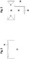
- FIG. 1 schematically shows an embodiment of the light curtain 1 according to the invention, which is used for detecting objects in a surveillance area.
- the light curtain 1 comprises a transmitter unit 2 and a receiver unit 3, which are arranged on opposite edges of the monitoring area. Both the transmitter unit 2 and the receiver unit 3 comprise a housing 4 in which optoelectronic elements are arranged.
- emitting emitters 6 are integrated as optoelectronic elements light beams, which are formed by LEDs or the like.
- the transmitters 6, not shown transmitting optics for beam shaping of the light beams 5 may be arranged downstream.
- the receiver unit 3 are provided as opto-electronic elements light beams 5 receiving receiver 7, which are formed by photodiodes or the like.
- the measuring field formed by the light rays 5, within which objects can be detected with the light curtain 1 extends over almost the entire length of the housing body 11. Since almost no projection on the housing body 11 is generated by the flat-building adapter 15 with the end caps 14 , The measuring field also extends over the entire length of the entire housing 4. By the end caps 13, 14 thus very small and negligible dead zones, within which no object detection can occur.
Landscapes
- Physics & Mathematics (AREA)
- General Physics & Mathematics (AREA)
- Spectroscopy & Molecular Physics (AREA)
- Life Sciences & Earth Sciences (AREA)
- General Life Sciences & Earth Sciences (AREA)
- Geophysics (AREA)
- Switches Operated By Changes In Physical Conditions (AREA)
- Burglar Alarm Systems (AREA)
Claims (8)
- Rideau lumineux (1) pour détecter des objets dans une zone de surveillance, comportant un agencement d'éléments optoélectroniques qui sont formés par des émetteurs (6) émettant des faisceaux lumineux (5) et des récepteurs (7) recevant des faisceaux lumineux (5), et comportant au moins un boîtier pour recevoir les éléments optoélectroniques, le boîtier comportant un corps de boîtier (11) sous forme d'un corps creux dans lequel les éléments optoélectroniques sont disposés l'un derrière l'autre à une certaine distance dans la direction de l'axe longitudinal du corps de boîtier (11), et le corps de boîtier (11) comportant à chacune de ses extrémités longitudinales une ouverture qui est fermée par des embouts (14),
dans lequel
au moins un capuchon d'extrémité (13) présente un adaptateur plat (15) qui ferme une ouverture dans le corps de boîtier (11) et auquel est relié un corps de capuchon (16) qui s'appuie latéralement contre le corps de boîtier (11) et reçoit des composants électroniques (18), et le corps de capuchon (16) portant avec une paroi plate contre une paroi latérale du corps de boîtier (11),
caractérisé en ce que l'adaptateur plat (15) d'un composant électronique (18) est en forme de plaque, et en ce que
les capuchons d'extrémité étant conçus pour la mise en cascade d'une pluralité de barrières immatérielles. - Rideau lumineux selon la revendication 1, caractérisé en ce qu'il comprend une unité émettrice comportant un premier boîtier (4) dans lequel sont intégrés des éléments optoélectroniques sous la forme d'émetteurs (6) émettant des faisceaux lumineux (5), et une unité réceptrice comportant un second boîtier (4) dans lequel sont intégrés des éléments optoélectroniques sous la forme de récepteurs (7) recevant les faisceaux lumineux.
- Rideau lumineux selon l'une des revendications 1 à 2, caractérisé en ce que chaque corps de boîtier (11) présente une paroi frontale avec une fenêtre (12),
à travers lequel les faisceaux lumineux (5) sont guidés, et en ce que le ou chaque corps de capuchon (16) d'un capuchon d'extrémité (13) repose contre une paroi latérale du corps de boîtier (11) opposée à la paroi avant. - Rideau lumineux selon la revendication 3, caractérisé en ce que le corps de boîtier (11) a une section transversale rectangulaire et en ce que le ou chaque corps de capuchon (16) est appuyé contre une paroi latérale du corps de boîtier (11) adjacente ou opposée à la paroi avant.
- Rideau lumineux selon l'une des revendications 1 à 4, caractérisé en ce que la forme de la paroi du corps de capuchon (16) épouse la forme de la paroi latérale.
- Rideau lumineux selon l'une des revendications 1 à 5, caractérisé en ce que des connexions électriques (19) sont intégrées dans le ou chaque corps de capuchon (16).
- Rideau lumineux selon l'une des revendications 1 à 6, caractérisé en ce que des composants électroniques (18) pour commander le rideau lumineux (1) sont prévus dans le ou chaque corps de capuchon (16).
- Rideau lumineux selon l'une des revendications 1 à 7, caractérisé en ce que des éléments de commande et/ou d'affichage sont prévus dans au moins un corps de capuchon (16).
Applications Claiming Priority (1)
| Application Number | Priority Date | Filing Date | Title |
|---|---|---|---|
| DE102012103651A DE102012103651A1 (de) | 2012-04-26 | 2012-04-26 | Lichtvorhang |
Publications (2)
| Publication Number | Publication Date |
|---|---|
| EP2657727A1 EP2657727A1 (fr) | 2013-10-30 |
| EP2657727B1 true EP2657727B1 (fr) | 2019-08-21 |
Family
ID=47891469
Family Applications (1)
| Application Number | Title | Priority Date | Filing Date |
|---|---|---|---|
| EP13159321.2A Active EP2657727B1 (fr) | 2012-04-26 | 2013-03-15 | Rideau lumineux |
Country Status (2)
| Country | Link |
|---|---|
| EP (1) | EP2657727B1 (fr) |
| DE (1) | DE102012103651A1 (fr) |
Families Citing this family (3)
| Publication number | Priority date | Publication date | Assignee | Title |
|---|---|---|---|---|
| CN106918846B (zh) * | 2017-03-29 | 2019-05-24 | 天奇自动化工程股份有限公司 | 基于组合式光电开关及光栅的防侵入检测装置 |
| CN110608670B (zh) * | 2019-09-06 | 2025-02-18 | 昆山东威科技股份有限公司 | 光幕检测装置及电化学处理设备 |
| ES3057169T3 (en) * | 2022-05-30 | 2026-02-26 | Refco Mfg Ltd | Sensor device and condensate water removal device with a sensor device |
Citations (3)
| Publication number | Priority date | Publication date | Assignee | Title |
|---|---|---|---|---|
| DE102005046478A1 (de) * | 2004-09-30 | 2006-06-14 | Omron Corp. | Photoelektrischer Mehrstrahl-Sensor |
| JP2007157556A (ja) * | 2005-12-06 | 2007-06-21 | Sunx Ltd | 多光軸光電センサ |
| US20110226938A1 (en) * | 2010-03-19 | 2011-09-22 | Keyence Corporation | Multi-Optical Axis Photoelectric Sensor |
Family Cites Families (9)
| Publication number | Priority date | Publication date | Assignee | Title |
|---|---|---|---|---|
| US5013911A (en) | 1988-05-27 | 1991-05-07 | Oki Electric Industry Co., Ltd. | Optical sensor unit with sealed optical element and cable connector |
| AU2001263460A1 (en) * | 2000-05-26 | 2001-12-11 | Mark R. Brent | Perimetric detection system and automated container |
| JP3788502B2 (ja) * | 2000-08-11 | 2006-06-21 | オムロン株式会社 | 光カーテン創成装置 |
| DE102004046725B4 (de) * | 2004-09-25 | 2007-08-09 | Sick Ag | Gehäuse für ein Lichtgitter |
| DE102006059547B4 (de) * | 2006-12-16 | 2009-05-07 | Leuze Lumiflex Gmbh + Co. Kg | Lichtschrankenanordnung |
| JP5137054B2 (ja) * | 2007-01-25 | 2013-02-06 | 株式会社キーエンス | 多光軸光電センサ |
| DE102007014170A1 (de) * | 2007-03-21 | 2008-09-25 | Sick Ag | Optoelektronische Sensoranordnung |
| DE202007010492U1 (de) | 2007-07-27 | 2007-10-18 | Sick Ag | Optoelektronische Sensoranordnung |
| DE202011051295U1 (de) * | 2011-09-14 | 2011-12-21 | Sick Ag | Lichtgitter |
-
2012
- 2012-04-26 DE DE102012103651A patent/DE102012103651A1/de not_active Withdrawn
-
2013
- 2013-03-15 EP EP13159321.2A patent/EP2657727B1/fr active Active
Patent Citations (3)
| Publication number | Priority date | Publication date | Assignee | Title |
|---|---|---|---|---|
| DE102005046478A1 (de) * | 2004-09-30 | 2006-06-14 | Omron Corp. | Photoelektrischer Mehrstrahl-Sensor |
| JP2007157556A (ja) * | 2005-12-06 | 2007-06-21 | Sunx Ltd | 多光軸光電センサ |
| US20110226938A1 (en) * | 2010-03-19 | 2011-09-22 | Keyence Corporation | Multi-Optical Axis Photoelectric Sensor |
Also Published As
| Publication number | Publication date |
|---|---|
| DE102012103651A1 (de) | 2013-10-31 |
| EP2657727A1 (fr) | 2013-10-30 |
Similar Documents
| Publication | Publication Date | Title |
|---|---|---|
| EP2667218B1 (fr) | Capteur 3D à économie d'énergie | |
| EP1933172B1 (fr) | Agencement de barrière lumineuse | |
| EP0232866A2 (fr) | Dispositif de commande de l'ouverture et/ou fermeture de portes à mouvement rapide | |
| EP2843447B1 (fr) | Barrière lumineuse | |
| EP1574776B1 (fr) | Dispositif de protection, en particulier barrière lumineuse | |
| EP2657727B1 (fr) | Rideau lumineux | |
| DE202007010493U1 (de) | Gehäuse für eine optoelektronische Sensoranordnung | |
| EP2053428B1 (fr) | Capteur optoélectronique | |
| DE102013100311C9 (de) | Sectionaltor mit lichtgittersicherungsvorrichtung | |
| DE102004022408B4 (de) | Optischer Sensor | |
| EP1288559B1 (fr) | Dispositif de surveillance optoélectronique | |
| EP1978378B1 (fr) | Dispositif de capteur optoélectronique | |
| EP0236755A1 (fr) | Dispositif de détection d'une interruption dans un espace situé entre l'émetteur et le récepteur d'un signal lumineux émis d'au moins un émetteur | |
| DE3346699A1 (de) | Bewegungsmelder | |
| DE29810418U1 (de) | Optoelektronische Vorrichtung | |
| DE202011000608U1 (de) | Montageprofil für ein Lichtgittergehäuse und Lichtgitter | |
| EP4220239B1 (fr) | Capteur optique | |
| DE10314852A1 (de) | Optoelektronische Zugangsabsicherung | |
| DE202005010358U1 (de) | Optoelektronisches Lichtgitter | |
| EP2477048A1 (fr) | Boîtier de barrière lumineuse | |
| DE102014101773A1 (de) | Lichtgitterelement, sowie Grundkörper hierfür, mit erleichterter Reinigbarkeit und erhöhter Widerstandsfähigkeit gegenüber äußeren Einflüssen | |
| DE202007010492U1 (de) | Optoelektronische Sensoranordnung | |
| EP2161593A1 (fr) | Capteur optoélectronique et procédé d'application | |
| DE19537051C1 (de) | Optoelektronische Sensoranordnung | |
| DE20313230U1 (de) | Optische Positionserfassungsvorrichtung |
Legal Events
| Date | Code | Title | Description |
|---|---|---|---|
| PUAI | Public reference made under article 153(3) epc to a published international application that has entered the european phase |
Free format text: ORIGINAL CODE: 0009012 |
|
| AK | Designated contracting states |
Kind code of ref document: A1 Designated state(s): AL AT BE BG CH CY CZ DE DK EE ES FI FR GB GR HR HU IE IS IT LI LT LU LV MC MK MT NL NO PL PT RO RS SE SI SK SM TR |
|
| AX | Request for extension of the european patent |
Extension state: BA ME |
|
| 17P | Request for examination filed |
Effective date: 20131029 |
|
| RBV | Designated contracting states (corrected) |
Designated state(s): AL AT BE BG CH CY CZ DE DK EE ES FI FR GB GR HR HU IE IS IT LI LT LU LV MC MK MT NL NO PL PT RO RS SE SI SK SM TR |
|
| STAA | Information on the status of an ep patent application or granted ep patent |
Free format text: STATUS: EXAMINATION IS IN PROGRESS |
|
| 17Q | First examination report despatched |
Effective date: 20170915 |
|
| RIC1 | Information provided on ipc code assigned before grant |
Ipc: G01V 8/20 20060101AFI20190326BHEP Ipc: G01J 1/02 20060101ALI20190326BHEP Ipc: G01V 8/22 20060101ALN20190326BHEP |
|
| RIC1 | Information provided on ipc code assigned before grant |
Ipc: G01V 8/22 20060101ALN20190409BHEP Ipc: G01V 8/20 20060101AFI20190409BHEP Ipc: G01J 1/02 20060101ALI20190409BHEP |
|
| GRAP | Despatch of communication of intention to grant a patent |
Free format text: ORIGINAL CODE: EPIDOSNIGR1 |
|
| STAA | Information on the status of an ep patent application or granted ep patent |
Free format text: STATUS: GRANT OF PATENT IS INTENDED |
|
| INTG | Intention to grant announced |
Effective date: 20190524 |
|
| RIN1 | Information on inventor provided before grant (corrected) |
Inventor name: SCHEDLBERGER, ROBERT Inventor name: MUECK, ARMIN Inventor name: DEUTSCHMANN, MARTIN Inventor name: LEHMANN, JOACHIM Inventor name: PATZ, JUERGEN Inventor name: SCHOENLEITNER, ARNOLD |
|
| GRAS | Grant fee paid |
Free format text: ORIGINAL CODE: EPIDOSNIGR3 |
|
| GRAA | (expected) grant |
Free format text: ORIGINAL CODE: 0009210 |
|
| STAA | Information on the status of an ep patent application or granted ep patent |
Free format text: STATUS: THE PATENT HAS BEEN GRANTED |
|
| AK | Designated contracting states |
Kind code of ref document: B1 Designated state(s): DE |
|
| RBV | Designated contracting states (corrected) |
Designated state(s): DE |
|
| REG | Reference to a national code |
Ref country code: DE Ref legal event code: R096 Ref document number: 502013013391 Country of ref document: DE |
|
| REG | Reference to a national code |
Ref country code: DE Ref legal event code: R097 Ref document number: 502013013391 Country of ref document: DE |
|
| PLBE | No opposition filed within time limit |
Free format text: ORIGINAL CODE: 0009261 |
|
| STAA | Information on the status of an ep patent application or granted ep patent |
Free format text: STATUS: NO OPPOSITION FILED WITHIN TIME LIMIT |
|
| 26N | No opposition filed |
Effective date: 20200603 |
|
| PGFP | Annual fee paid to national office [announced via postgrant information from national office to epo] |
Ref country code: DE Payment date: 20260319 Year of fee payment: 14 |