EP2657807A2 - Support pour dispositif électronique portable - Google Patents
Support pour dispositif électronique portable Download PDFInfo
- Publication number
- EP2657807A2 EP2657807A2 EP13165020.2A EP13165020A EP2657807A2 EP 2657807 A2 EP2657807 A2 EP 2657807A2 EP 13165020 A EP13165020 A EP 13165020A EP 2657807 A2 EP2657807 A2 EP 2657807A2
- Authority
- EP
- European Patent Office
- Prior art keywords
- supporting plate
- main supporting
- holder
- electronic device
- portable electronic
- Prior art date
- Legal status (The legal status is an assumption and is not a legal conclusion. Google has not performed a legal analysis and makes no representation as to the accuracy of the status listed.)
- Withdrawn
Links
Images





Classifications
-
- A—HUMAN NECESSITIES
- A45—HAND OR TRAVELLING ARTICLES
- A45C—PURSES; LUGGAGE; HAND CARRIED BAGS
- A45C11/00—Receptacles for purposes not provided for in groups A45C1/00-A45C9/00
-
- A—HUMAN NECESSITIES
- A45—HAND OR TRAVELLING ARTICLES
- A45C—PURSES; LUGGAGE; HAND CARRIED BAGS
- A45C11/00—Receptacles for purposes not provided for in groups A45C1/00-A45C9/00
- A45C11/003—Receptacles for purposes not provided for in groups A45C1/00-A45C9/00 for storing portable computing devices, e.g. laptops, tablets or calculators
-
- G—PHYSICS
- G06—COMPUTING OR CALCULATING; COUNTING
- G06F—ELECTRIC DIGITAL DATA PROCESSING
- G06F1/00—Details not covered by groups G06F3/00 - G06F13/00 and G06F21/00
- G06F1/16—Constructional details or arrangements
- G06F1/1613—Constructional details or arrangements for portable computers
- G06F1/1626—Constructional details or arrangements for portable computers with a single-body enclosure integrating a flat display, e.g. Personal Digital Assistants [PDAs]
-
- A—HUMAN NECESSITIES
- A45—HAND OR TRAVELLING ARTICLES
- A45C—PURSES; LUGGAGE; HAND CARRIED BAGS
- A45C2200/00—Details not otherwise provided for in A45C
- A45C2200/15—Articles convertible into a stand, e.g. for displaying purposes
-
- G—PHYSICS
- G06—COMPUTING OR CALCULATING; COUNTING
- G06F—ELECTRIC DIGITAL DATA PROCESSING
- G06F2200/00—Indexing scheme relating to G06F1/04 - G06F1/32
- G06F2200/16—Indexing scheme relating to G06F1/16 - G06F1/18
- G06F2200/163—Indexing scheme relating to constructional details of the computer
- G06F2200/1633—Protecting arrangement for the entire housing of the computer
Definitions
- Holders are widely used to protect portable electronic devices and support the portable electronic device for a user to, for example, read an eBook or watch video.
- it can be difficult to carry the holder and the electronic device at the same time. Therefore, there is room for improvement within the art.
- a holder for holding and supporting a portable electronic device.
- the holder comprises at least one sheet.
- a base plate, a first main supporting plate, a second main supporting plate, two first side supporting plates, and two second side supporting plates are located on the at least one sheet; the base plate, the first main supporting plate and the second main supporting plate are foldable relative to each other, the two first side supporting plates are symmetrically positioned on opposite sides of the first main supporting plate, the two second side supporting plates are symmetrically positioned on opposite sides of the second main supporting plate, when the holder is folded, the base plate, the first main supporting plate, the second main supporting plate, the first side supporting plates, and the second side supporting plates cooperatively form a three-dimensional structure that can support the portable electronic device at an angle relative to the at least one sheet without collapsing.
- a foldable holder for holding and supporting a portable electronic device.
- the holder comprises a first outer sheet and a second outer sheet connected to the first outer sheet.
- a receiving space is formed between the second outer sheet and the first outer sheets for receiving the portable electronic device.
- An entrance is defined to communicate with the receiving space. The entrance allows the portable electronic device to be inserted into the receiving space.
- a base plate, a first main supporting plate, a second main supporting plate, two first side supporting plates, and two second side supporting plates are located on the second outer sheet; the base plate, the first main supporting plate and the second main supporting plate are folded relative to each other, the two first side supporting plates are symmetrically positioned on opposite sides of the first main supporting plate, the two second side supporting plates are symmetrically positioned on opposite sides of the second main supporting plate; a latching piece is formed on the base plate, the latching piece has a bendable portion; the first main supporting plate, the second main supporting plate, the two first side supporting plates, and the two second side supporting plates are folded relative to each other until the second main supporting plate is held by the latching piece, the first main supporting plate, the second main supporting plate, the two first side supporting plates, and the two second side supporting plates cooperatively form a three-dimensional structure that can support the portable electronic device at an angle relative to the second outer sheet without collapsing.
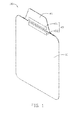
- FIG. 1 is an isometric view of a holder, in accordance with a first exemplary embodiment.
- FIG. 2 is similar to FIG. 1 , but shown from another aspect.
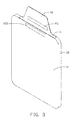
- FIG. 3 is an isometric view of the holder, showing the holder for receiving a portable electronic device.
- FIG. 4 is similar to FIG. 2 , showing the holder in a state of being partially folded.
- FIG. 5 is similar to FIG. 4 , showing the holder folded as a support.
- FIG. 6 is similar to FIG. 5 , showing the latching portion of the holder to be bent.
- FIG. 7 shows the holder supporting the portable electronic device in a first state.
- FIG. 8 shows the holder supporting the portable electronic device in a second state.
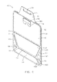
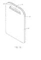
- FIG. 9 is an isometric view of a holder, in accordance with a second exemplary embodiment.
- FIG. 10 is similar to FIG. 9 , but shown from another aspect.
- FIG. 11 is an isometric view of the holder, showing the holder for receiving a portable electronic device.
- FIG. 12 is similar to FIG. 10 , showing the holder in a state of being partially folded.
- FIG. 13 is similar to FIG. 12 , showing the holder folded as a support.
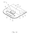
- FIG. 14 is similar to FIG. 13 , showing the latching portion of the holder to be bent.
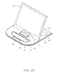
- FIG. 15 shows the holder supporting the portable electronic device in a first state.
- FIG. 16 shows the holder supporting the portable electronic device in a second state.
- FIGS. 1-2 , and 7 show an exemplary embodiment of a holder 100.
- the holder 100 can receive and protect a portable electronic device 200, and can also support and hold the portable electronic device 200.
- FIGs. 2 and 3 show that the holder 100 includes a first outer sheet 10, a second outer sheet 20, an expandable portion 30, and a covering portion 40.
- a receiving space (not labeled) is defined between the first outer sheet 10 and the second outer sheet 20 for receiving the portable electronic device 200.
- the first outer sheet 10 and the second outer sheet 20 are connected to each other along their edges by the expandable portion 30, leaving an entrance 31 that allows the portable electronic device 200 to be inserted into the receiving space.
- the holder 100 shown herein for illustrative purpose includes the first outer sheet 10 and the expandable portion 30; however, the expandable portion 30 may be omitted and the first and second outer sheets connected to each other along their perimeters.
- first outer sheet 10 and the second outer sheet 20 are made of soft material, e.g., fiber, cotton, vinyl, thermoplastics.
- the covering portion 40 is flexible and is used to cover the entrance 31.
- the covering portion 40 may be an extension of the second outer sheet 20.
- the covering portion 40 is trapezoid-shaped, however, any other shapes may also be used.
- a locking member 45 is configured for retaining the covering portion 40 on the first outer sheet 10 for closing the holder 100.
- the locking member 45 includes a first fastening tape 451 attached on one surface of the covering portion 40, and a second fastening tape 452 attached on the second outer sheet 10.
- the first fastening tape 451 may be adhered to the second fastening tape 452 for mounting the covering portion 40 to the first outer sheet 10.
- the covering portion 40 defines a slot 41 on another surface thereof.
- a tongue portion 50 is formed in the slot 41. One edge of the tongue portion 50 is connected to the covering portion 40.
- FIGs. 6 and 8 show that the tongue portion 50 may be bent away from the covering portion 40 to allow the portable electronic device 200 to be supported by the tongue portion 50.
- FIG. 2 shows that a base plate 61, a first main supporting plate 62, a second main supporting plate 63, two first side supporting plates 64, and two second side supporting plates 66 are formed on the second outer sheet 20.
- the base plate 61, the four supporting plates 62,63,64 66 are made of rigid material.
- the base plate 61 is rectangular and adjacent to the covering portion 40.
- the first main supporting plate 62 is positioned between the base plate 61 and the second main supporting plate 63.
- the first main supporting plate 62 and the second main supporting plate 63 are isosceles trapezoid-shaped.
- the two first side supporting plates 64 are symmetrically positioned at two sides of the first main supporting plate 62.
- the two second side supporting plates 64 are symmetrically positioned at two sides of the second main supporting plate 63.
- a first folding region 71 is positioned between the base plate 61 and the first main supporting plate 62.
- a second folding region 73 is positioned between the first main supporting plate 62 and the second main supporting plate 63.
- the first side supporting plates 64 and the second side supporting plates 66 are triangular, and are respectively positioned at two sides of the second folding region 73.
- the first main supporting plate 62 includes two side edges 623.
- Each first side supporting plate 64 has a sloping edge 643, which is adjacent to and parallel to one of the side edges 623 of the first main supporting plate 62.
- the second main supporting plate 63 includes two side edges 633.
- Each second side supporting plate 66 has a sloping edge 663, which is adjacent to and parallel to one of the side edges 633 of the second main supporting plate 633.
- a third folding region 75 is positioned between the first main supporting plate 62 and the first side supporting plate 64
- a fourth folding region 77 is positioned between the second main supporting plate 63 and the second side supporting plate 66.
- the base plate 61, the first main supporting plate 62, the second main supporting plate 63, the first side supporting plates 64 and the second side supporting plates 66 can be folded relative to each other along the folding regions 71, 73, 75, 77.
- the base plate 61, the first main supporting plate 62, the second main supporting plate 63, the first side supporting plates 64 and the second side supporting plates 66 are made of rigid material, the base plate 61, the first main supporting plate 62, the second main supporting plate 63, the first side supporting plates 64 and the second side supporting plates 66 cannot be folded themselves.
- the base plate 61 has a latching piece 55 formed thereon adjacent to the covering portion 40.
- the latching piece 55 has a bendable portion 551.
- the bendable portion 551 may be bent away the base plate 61 to allow the second main supporting plate 63 to be supported thereon.
- FIG.3 shows that when the portable electronic device 200 needs to be received in the holder 100, the covering portion 40 is folded over to uncover the entrance 31.
- the device 200 can then be inserted into the receiving space of the holder 100 via the entrance 31 for storage.
- the first fastening tape 451 is adhered to the second fastening tape 452 for mounting the covering portion 40 to the first outer sheet 10.
- FIGs. 4 and 5 shows that in order to fold the holder 100 to form a support, the first main supporting plate 62 and the second main supporting plate 63 are folded toward the base plate 61 along the first folding region 71 and the second folding region 73 until the second supporting plate 63 stands on the base plate 61. Then, the first side supporting plate 64 and the second side supporting plate 66 at each side of the first main supporting plate 62 and the second main supporting plate 63 is folded along the third folding region 75 and the fourth folding region 77.
- the bendable portion 551 is bent to allow the second main supporting plate 63 to be supported by the bendable portion 551.
- the first main first supporting plate 62 is angled with the base plate 61, the second main supporting plate 63are supported by the base plate 61, and each of the first side supporting plates 64 and the second side supporting plates 66 are angled with the first main supporting plate 62 and the second main supporting plate 63.
- the base plate 61, the first main supporting plate 62, the second main supporting plate 63, the first side supporting plates 64, and the second side supporting plates 66 can form a three-dimensional structure that will not collapse.
- FIG. 7 shows that the portable electronic device 200 is set on the holder 100 as a support. One end of the portable electronic device 200 is supported between the bendable portion 551 and the second main supporting plate 62.
- the portable electronic device 200 is supported by the first main supporting plate 62, the second main supporting plate 63, the first side supporting plates 64, and the second side supporting plates 66 at an angle.
- users can comfortably view the display of the portable electronic device 200.
- FIGs. 6 and 8 show that if the viewed angled of the portable electronic device 200 needs to be adjusted, the tongue portion 50 can be bent around the edge along a direction away from the covering portion 40. The portable electronic device 200 is held on the tongue portion 50. Thus, users can comfortably view the display of the portable electronic device 200 at a different angle.
- FIGS. 9 and 10 show a second exemplary embodiment of a holder 100.
- the holder 100 can receive and protect a portable electronic device 200, and can also support and hold the portable electronic device 200.
- FIGs. 10 and 11 show that the holder 100 includes a first outer sheet 10, a second outer sheet 20, a expandable portion 30, and a handle portion 40.
- a receiving space (not labeled) is defined between the second outer sheet 20 and the first outer sheet 10 for receiving the portable electronic device 200.
- the second outer sheet 20 and the first outer sheet 10 are connected to each other along their edges by the expandable portion 30, leaving an entrance 31 that allows the portable electronic device 200 to be inserted into the receiving space.
- the handle portion 40 includes two extending sheets, one extending sheet extending from the first outer sheet 10 and the other extending sheet extending from the second outer sheet 20.
- the handle portion 40 defines a through hole 41 passing through the two extending sheets.
- the through hole 41 makes the holder 100 convenient to carry.
- two attractive magnet members may be attached to the two extending sheets for preventing the portable electronic device 100 from separating from the entrance 31.
- the handle portion 40 defines a slot 21 on one side of the through hole 41.
- a tongue portion 50 is formed in the slot 21.
- One edge of the tongue portion 50 is connected to the handle portion 40. Referring to FIGs. 6 and 8 , the tongue portion 50 may be bent away the handle portion 40 to allow the portable electronic device 200 to be supported by the tongue portion 50.
- the handle portion 40 is opened to expose the entrance 31.
- the device 200 can then be inserted into the receiving space of the holder 100 via the entrance 31 for storage.
- FIGs. 12 and 13 show that in order to fold the holder 100 to form a support, the first main supporting plate 62 and the second main supporting plate 63 are folded toward the base plate 61 along the first folding region 71 and the second folding region 73 until the second main supporting plate 63 stands on the base plate 61. Then, the first side supporting plate 64 and the second side supporting plate 66 at each side of the first main supporting plate 62 and the second main supporting plate 63 is folded along the third folding region 75 and the fourth folding region 77. The bendable portion 551 is folded to allow the second main supporting plate 63 to be supported by the bendable portion 551.
- the first main first supporting plate 62 is angled with the base plate 61
- the second main supporting plate 63 is supported by the base plate 61
- each of the first side supporting plates 64 and the second side supporting plates 66 are angled with the first main supporting plate 62 and the second main supporting plate 63.
- the base plate 61, the first main supporting plate 62, the second main supporting plate 63, the first side supporting plates 64, and the second side supporting plates 66 can form a three-dimensional structure that will not collapse.
- FIG. 15 shows that the portable electronic device 200 is set on the holder 100 as a support. One end of the portable electronic device 200 is supported between the foldable piece 551 and the second main supporting plate 62.
- the portable electronic device 200 is supported by the first main supporting plate 62, the second main supporting plate 63, the first side supporting plates 64, and the second side supporting plates 66 at an angle.
- users can comfortably view the display of the portable electronic device 200.
- FIGs. 14 and 16 show that if the viewed angled of the portable electronic device 200 needs to be adjusted, the tongue portion 50 can be bent around the edge along a direction far away from the covering portion 40. The portable electronic device 200 is held on the tongue portion 50. Thus, users can comfortably view the display of the portable electronic device 200 at a different angle.
Landscapes
- Engineering & Computer Science (AREA)
- Theoretical Computer Science (AREA)
- Computer Hardware Design (AREA)
- Human Computer Interaction (AREA)
- Physics & Mathematics (AREA)
- General Engineering & Computer Science (AREA)
- General Physics & Mathematics (AREA)
- Telephone Set Structure (AREA)
- Casings For Electric Apparatus (AREA)
- Purses, Travelling Bags, Baskets, Or Suitcases (AREA)
Applications Claiming Priority (2)
| Application Number | Priority Date | Filing Date | Title |
|---|---|---|---|
| TW101208015U TWM439327U (en) | 2012-04-27 | 2012-04-27 | Supporting bracket for electronic device |
| TW101208017U TWM442681U (en) | 2012-04-27 | 2012-04-27 | Supporting bracket for electronic device |
Publications (2)
| Publication Number | Publication Date |
|---|---|
| EP2657807A2 true EP2657807A2 (fr) | 2013-10-30 |
| EP2657807A3 EP2657807A3 (fr) | 2014-04-23 |
Family
ID=48193102
Family Applications (1)
| Application Number | Title | Priority Date | Filing Date |
|---|---|---|---|
| EP13165020.2A Withdrawn EP2657807A3 (fr) | 2012-04-27 | 2013-04-23 | Support pour dispositif électronique portable |
Country Status (1)
| Country | Link |
|---|---|
| EP (1) | EP2657807A3 (fr) |
Cited By (4)
| Publication number | Priority date | Publication date | Assignee | Title |
|---|---|---|---|---|
| WO2020225546A1 (fr) * | 2019-05-03 | 2020-11-12 | Colebrook Bosson & Saunders (Products) Limited | Étui convertible pour dispositif électronique portatif |
| EP4162835A4 (fr) * | 2020-06-03 | 2023-11-08 | Shenzhen Lemore Marketing Consultancy Co., Ltd | Sac pliable |
| KR102730580B1 (ko) * | 2023-09-08 | 2024-11-15 | (주)식스플로어랩 | 태블릿 컴퓨터 케이스 |
| KR102849481B1 (ko) * | 2024-12-03 | 2025-08-21 | 주식회사 아우라플로 | 카드 슬롯 구조체 |
Family Cites Families (2)
| Publication number | Priority date | Publication date | Assignee | Title |
|---|---|---|---|---|
| EP0823377B1 (fr) * | 1996-07-30 | 2000-10-11 | The Procter & Gamble Company | Procédé pour l'emballage d'articles absorbants et pour la fabrication simultanée d'une poignée |
| TWI491335B (zh) * | 2011-01-18 | 2015-07-01 | Chiun Mai Comm Systems Inc | 多功能保護套 |
-
2013
- 2013-04-23 EP EP13165020.2A patent/EP2657807A3/fr not_active Withdrawn
Non-Patent Citations (1)
| Title |
|---|
| None |
Cited By (5)
| Publication number | Priority date | Publication date | Assignee | Title |
|---|---|---|---|---|
| WO2020225546A1 (fr) * | 2019-05-03 | 2020-11-12 | Colebrook Bosson & Saunders (Products) Limited | Étui convertible pour dispositif électronique portatif |
| US11950668B2 (en) | 2019-05-03 | 2024-04-09 | Colebrook Bosson & Saunders (Products) Limited | Convertible case for portable electronic device |
| EP4162835A4 (fr) * | 2020-06-03 | 2023-11-08 | Shenzhen Lemore Marketing Consultancy Co., Ltd | Sac pliable |
| KR102730580B1 (ko) * | 2023-09-08 | 2024-11-15 | (주)식스플로어랩 | 태블릿 컴퓨터 케이스 |
| KR102849481B1 (ko) * | 2024-12-03 | 2025-08-21 | 주식회사 아우라플로 | 카드 슬롯 구조체 |
Also Published As
| Publication number | Publication date |
|---|---|
| EP2657807A3 (fr) | 2014-04-23 |
Similar Documents
| Publication | Publication Date | Title |
|---|---|---|
| US9033147B2 (en) | Holder for portable electronic device | |
| US8919544B2 (en) | Holder for portable electronic device | |
| US20130284866A1 (en) | Holder for portable electronic device | |
| US8424829B2 (en) | Holder for portable electronic device | |
| EP2505904A2 (fr) | Support pour dispositif électronique portable | |
| US8544639B2 (en) | Holder for portable electronic device background | |
| US8162283B1 (en) | Stand for supporting a portable electronic device | |
| US9677704B1 (en) | Mobile telephone holder and display | |
| KR200451310Y1 (ko) | 지갑형 휴대폰 케이스 | |
| US9259068B2 (en) | Holder for portable electronic device | |
| KR200474403Y1 (ko) | 거치기능을 구비한 스마트폰용 카드지갑 | |
| US20120012483A1 (en) | Protective apparatus for tablet electronic device | |
| EP2647306A1 (fr) | Appareil de protection pour dispositif électronique à tablette | |
| US20140224676A1 (en) | Low profile protective cover configurable as a stand with integrated battery | |
| US20130284613A1 (en) | Holder for portable electronic device | |
| EP2657587A2 (fr) | Support pour dispositif électronique portable | |
| US11371649B2 (en) | Reusable adhesive mount device for portable electronics | |
| US20120267269A1 (en) | Protective case for electronic device | |
| JP2015046074A (ja) | 保護カバー | |
| WO2024027497A1 (fr) | Dispositif de protection et de support d'appareil mobile | |
| US9816664B2 (en) | Support for electronic device | |
| US10444790B1 (en) | Electronic device carrying case and display stand | |
| KR200479258Y1 (ko) | 휴대단말기 케이스 | |
| US20130334943A1 (en) | Holder for portable electronic device | |
| JP2021068123A (ja) | 保護具 |
Legal Events
| Date | Code | Title | Description |
|---|---|---|---|
| PUAI | Public reference made under article 153(3) epc to a published international application that has entered the european phase |
Free format text: ORIGINAL CODE: 0009012 |
|
| AK | Designated contracting states |
Kind code of ref document: A2 Designated state(s): AL AT BE BG CH CY CZ DE DK EE ES FI FR GB GR HR HU IE IS IT LI LT LU LV MC MK MT NL NO PL PT RO RS SE SI SK SM TR |
|
| AX | Request for extension of the european patent |
Extension state: BA ME |
|
| PUAL | Search report despatched |
Free format text: ORIGINAL CODE: 0009013 |
|
| AK | Designated contracting states |
Kind code of ref document: A3 Designated state(s): AL AT BE BG CH CY CZ DE DK EE ES FI FR GB GR HR HU IE IS IT LI LT LU LV MC MK MT NL NO PL PT RO RS SE SI SK SM TR |
|
| AX | Request for extension of the european patent |
Extension state: BA ME |
|
| RIC1 | Information provided on ipc code assigned before grant |
Ipc: G06F 1/16 20060101AFI20140318BHEP Ipc: B65B 61/14 20060101ALI20140318BHEP |
|
| STAA | Information on the status of an ep patent application or granted ep patent |
Free format text: STATUS: THE APPLICATION IS DEEMED TO BE WITHDRAWN |
|
| 18D | Application deemed to be withdrawn |
Effective date: 20141024 |