EP2658038A1 - Dispositif de protection et procédé de fabrication d'un dispositif de protection - Google Patents
Dispositif de protection et procédé de fabrication d'un dispositif de protection Download PDFInfo
- Publication number
- EP2658038A1 EP2658038A1 EP13001985.4A EP13001985A EP2658038A1 EP 2658038 A1 EP2658038 A1 EP 2658038A1 EP 13001985 A EP13001985 A EP 13001985A EP 2658038 A1 EP2658038 A1 EP 2658038A1
- Authority
- EP
- European Patent Office
- Prior art keywords
- housing
- cable
- housing element
- connector
- sealing element
- Prior art date
- Legal status (The legal status is an assumption and is not a legal conclusion. Google has not performed a legal analysis and makes no representation as to the accuracy of the status listed.)
- Granted
Links
Images



Classifications
-
- H—ELECTRICITY
- H01—ELECTRIC ELEMENTS
- H01R—ELECTRICALLY-CONDUCTIVE CONNECTIONS; STRUCTURAL ASSOCIATIONS OF A PLURALITY OF MUTUALLY-INSULATED ELECTRICAL CONNECTING ELEMENTS; COUPLING DEVICES; CURRENT COLLECTORS
- H01R13/00—Details of coupling devices of the kinds covered by groups H01R12/70 or H01R24/00 - H01R33/00
- H01R13/46—Bases; Cases
- H01R13/52—Dustproof, splashproof, drip-proof, waterproof, or flameproof cases
- H01R13/5205—Sealing means between cable and housing, e.g. grommet
-
- H—ELECTRICITY
- H01—ELECTRIC ELEMENTS
- H01R—ELECTRICALLY-CONDUCTIVE CONNECTIONS; STRUCTURAL ASSOCIATIONS OF A PLURALITY OF MUTUALLY-INSULATED ELECTRICAL CONNECTING ELEMENTS; COUPLING DEVICES; CURRENT COLLECTORS
- H01R13/00—Details of coupling devices of the kinds covered by groups H01R12/70 or H01R24/00 - H01R33/00
- H01R13/46—Bases; Cases
- H01R13/52—Dustproof, splashproof, drip-proof, waterproof, or flameproof cases
- H01R13/5202—Sealing means between parts of housing or between housing part and a wall, e.g. sealing rings
-
- H—ELECTRICITY
- H01—ELECTRIC ELEMENTS
- H01R—ELECTRICALLY-CONDUCTIVE CONNECTIONS; STRUCTURAL ASSOCIATIONS OF A PLURALITY OF MUTUALLY-INSULATED ELECTRICAL CONNECTING ELEMENTS; COUPLING DEVICES; CURRENT COLLECTORS
- H01R13/00—Details of coupling devices of the kinds covered by groups H01R12/70 or H01R24/00 - H01R33/00
- H01R13/46—Bases; Cases
- H01R13/52—Dustproof, splashproof, drip-proof, waterproof, or flameproof cases
- H01R13/5219—Sealing means between coupling parts, e.g. interfacial seal
- H01R13/5221—Sealing means between coupling parts, e.g. interfacial seal having cable sealing means
-
- H—ELECTRICITY
- H01—ELECTRIC ELEMENTS
- H01R—ELECTRICALLY-CONDUCTIVE CONNECTIONS; STRUCTURAL ASSOCIATIONS OF A PLURALITY OF MUTUALLY-INSULATED ELECTRICAL CONNECTING ELEMENTS; COUPLING DEVICES; CURRENT COLLECTORS
- H01R13/00—Details of coupling devices of the kinds covered by groups H01R12/70 or H01R24/00 - H01R33/00
- H01R13/46—Bases; Cases
- H01R13/502—Bases; Cases composed of different pieces
- H01R13/506—Bases; Cases composed of different pieces assembled by snap action of the parts
-
- H—ELECTRICITY
- H01—ELECTRIC ELEMENTS
- H01R—ELECTRICALLY-CONDUCTIVE CONNECTIONS; STRUCTURAL ASSOCIATIONS OF A PLURALITY OF MUTUALLY-INSULATED ELECTRICAL CONNECTING ELEMENTS; COUPLING DEVICES; CURRENT COLLECTORS
- H01R13/00—Details of coupling devices of the kinds covered by groups H01R12/70 or H01R24/00 - H01R33/00
- H01R13/58—Means for relieving strain on wire connection, e.g. cord grip, for avoiding loosening of connections between wires and terminals within a coupling device terminating a cable
- H01R13/5845—Means for relieving strain on wire connection, e.g. cord grip, for avoiding loosening of connections between wires and terminals within a coupling device terminating a cable the strain relief being achieved by molding parts around cable and connections
Definitions
- the invention relates to a protective device for a method for producing a protective device.
- Such a protection device is used to prevent damage to a connector, in particular a standardized connector, for example, when inadvertently pulled on a cable.
- the protection device prevents the penetration of solid and liquid bodies, e.g. Moisture, water, etc., so that even in a dusty or humid environment contacting errors or short circuits can be prevented within or on the standardized connector.
- a similar protection device is for example from the DE 10 2007 004 900 A1 known.
- the protection device known from this document consists of a pair of couplable housing elements, which is designed for receiving a plug connection. This protective device is separable by decoupling the housing elements, while the connector is protected in the connected state by the pair of housing elements by the connector in the coupled housing elements is at least partially received.
- the object of the invention is to provide a protective device for a connector which provides improved protection of the connector provides.
- the protection device serves to protect a connector connected to a cable.
- the protective device has a first housing element, which is coupled or can be coupled to a second housing element of the protective device.
- the first housing element at least partially receives the connector
- the second housing element receives the cable at least partially.
- the first housing element, the second housing element and the cable are connected to one another in a material-locking manner by a sealing element.
- the protection device can be assembled in two stages or steps: In a first connection stage or a first connection step, the two housing elements are coupled to one another such that they comprise the connector and a cable section. The connector and the cable are electrically connected together.
- a sealing element is inserted, through which both the first housing element, the second housing element and the cable are materially connected to one another. Due to the couplable design of the two housing elements, the two housing elements of the protection device can be coupled to each other in a simple manner and assembled. Due to the cohesive connection via or by means of the sealing element, the two housing elements are inseparably connected to each other. Thereby, the connection of the two housing elements with each other and / or with the cable is no longer separable without damage or even destruction of at least one of the components of the protective device.
- the sealing element By means of the sealing element thus a secure connection is provided, which connects the two housing elements and the cable firmly and inseparably.
- the protective device provides a safe and robust unit with a provided high strength.
- cohesive connection is understood to mean an "intimate connection" between two bodies.
- this is a direct, direct mechanical contacting in a contact area or a contact area.
- the intimate connection can be made by shrinking a peripheral body onto another enclosed body, so that the circumferential body in the contact region exerts a force or mechanical stress on the enclosed body, so that by elastic deformation of the two bodies in the contact area there is essentially no gap between the two bodies.
- the two bodies may be fused together in the contact area.
- the cohesive connection may be a chemical compound and / or a compound in which the connection partners are connected to one another by atomic and / or molecular forces. Due to the material bond, it may be possible in particular that a separation of the elements connected by means of material connection, z, B. first housing element and / or second housing element and / or cable or cable sheath only by destruction of at least one, in particular all of the connected elements is possible.
- the sealing element is at least partially injected into a cavity between the first and the second housing element.
- a cavity is formed between the first housing element and the second housing element at at least one location. This cavity is filled in the irreversible connection of the protective device with each other by the sealing element, in particular completely filled. there the cavity is at least partially formed between the first housing member, the second housing member and the cable.
- the protective device seals the connector, in particular the cable-side region of the connector from moisture-proof to IP67.
- IP67 is a generally accepted standard for defining the moisture density of an article.
- the protection device meets the requirements of IP67. This provides good moisture and dust protection.
- the protective device seals the connection region between the cable and the connector and / or the region in which the cable is passed through the protective device and the Verbding of the two housing elements from moisture-tight.
- moisture-proof is understood as meaning a leak-tightness or a barrier with respect to a fluid, in particular water or water vapor, wherein the flow or displacement of the moisture is prevented.
- a contact area between two bodies, which are in particular intimately connected to each other moisture-proof if and only if a fluid can not penetrate along the (area) contact area in the interior of the connector between connector and cable.
- the sealing element surrounds the cable and / or the second housing element at least partially and / or is cohesively thereto.
- the second housing element is designed for at least partially receiving the cable. This may mean that a part of the cable is passed through the second housing element.
- the second housing element surrounds or surrounds the cable radially from the outside.
- the sealing element is arranged so that it encloses both the cable radially from the outside to a portion of the cable, as well as a part of the second housing member.
- a statically particularly favorable connection is provided which counteracts in particular a relative movement of the sealing element and / or the second housing member relative to the cable in Jardinausbreitungsraum.
- the cable propagation direction may be parallel to an axial direction of the cable.
- the second housing element is at least partially insertable into the first housing element, wherein the sealing element is at least partially surrounded by the first housing element.
- the second housing element is designed to receive the cable.
- the second housing element is preferably arranged in the immediate vicinity of the cable.
- the first housing element for at least partially receiving the connector can be coupled to the second housing element.
- the cable can be arranged at least partially in the first housing element.
- the coupling of the first and second housing element can be effected in particular by an at least partial insertion of the second housing element into the first housing element.
- the coupled connection of the two housing elements is materially reinforced by the sealing element.
- the sealing element consists of an elastic polymer.
- an elastic polymer By an elastic polymer, a particularly cost-effective and efficient cohesive connection can be provided.
- an elastic polymer can be injected in a simple operation in a cavity between the first housing member and the second housing member.
- the sealing element is formed at least 1 mm thick between the first housing element and the second housing element.
- the sealing element is not a mere adhesive layer, but is designed as an independent component of the protective device. It is so injected between the two housing elements that there is a cavity of a minimum thickness of 1 mm distance between the first housing member and the second housing member fills.
- the sealing element has a non-negligible volume. Because the sealing element has its own volume, the sealing element can fill in (unwanted) cavities in which moisture or dust could penetrate.
- the sealing element may also be formed from 0.1 mm to 20 mm, from 0.25 mm to 5 mm thick, in particular from 1 mm to 2 mm thick.
- the second housing element has at least one injection hole, which is filled by the sealing element and which connects a region of the sealing element which surrounds the cable, and in particular is materially connected to the cable, with a region of the sealing element, which between the first Housing element and the second housing element is arranged. Due to the formation of spray holes in the second housing element, different hollow regions or cavities can be filled in the interior of the protective device during the injection of the sealing element by means of the sealing element. As a result, various components of the protective device can be connected to one another in a material-locking manner by means of the sealing element. For example, be formed not two spray holes, which are preferably opposite.
- the first housing element has a sealing lip which, in a plugged-in state of the connector, seals a plug connection of the plug connector with the socket in a moisture-proof manner to IP67.
- the sealing lip is arranged on the side of the first housing element, which is designed and provided to be connected in the insertion direction of the connector with a socket or socket. When inserting the connector, the sealing lip is brought into contact with the socket or the socket.
- the sealing lip may be formed in particular of an elastically deformable material, which is compressed during the insertion process and thus provides a tight connection.
- the sealing lip causes a seal between the connector and the socket and / or the socket.
- the protective device itself, and in particular the sealing element provides a seal between the plug and the cable.
- the sealing lip and the sealing element together cause a moisture-tight seal both the connector (in particular by the sealing lip) and the connection region between the connector and the cable (in particular by the sealing element), ie the entire connector.
- the entire plug can be moisture-proof in accordance with IP67.
- one of the first or second housing member has a receptacle into which at least a portion of the other of the first and second housing member is at least partially insertable to couple the first housing member to the second housing member.
- the receptacle and the section provide for a coupling of the two housing elements with each other. In the coupled state, the two housing elements of the protection device are connected together.
- the first housing element may be coupled to the second housing element by a positive connection. Due to the positive connection, a decoupling of the two housing elements from each other, in particular during introduction of the sealing element is avoided. This allows both a safe insertion or injection of the sealing element, as well as a force relief between the two housing elements during drying of the sealing element. Additionally or alternatively, the first housing element may be coupled to the second housing element by a non-positive connection.
- the connector is designed as a standardized industrial plug according to an industry standard or industry standard.
- the protective device according to the invention can be used in this embodiment for any standard industrial plug.
- a protection device is provided which is intended for use with an RJ plug.
- RJ stands for "registered jack", ie for an Ethernet plug, USB plug, Firewire, power plug, DVI plug. HDMI connector, etc.
- the second housing element has a cable section which encloses a section of the cable such that a contact region between the plug connector and electrical lines of the cable is formed substantially free of the sealing element. As a result, sticking and damage to the contact area during injection of the sealing element is avoided.
- At least a part of the cable can first be performed by the second housing element and the connector can be inserted into the first housing element such that it is at least partially inserted into the first housing element.
- the method is used in particular for producing a protective device for a connector according to one of claims 1 to 13.
- FIG. 1 shows a perspective view of a protective device.
- the protection device surrounds a connector 10, which is electrically and mechanically connected to a cable 20.
- the protective device has a first housing element 30, a second housing element 40 and a sealing element 50.
- the first housing element 30 surrounds the connector 10.
- the first housing member 30 encloses the connector 10 such that a contact surface 11 of the connector 10 remains completely free.
- the contact surface 11 of the connector 10 is designed and intended to be inserted into a socket or socket to provide there electrical contact between the connector 10 and the socket or socket.
- the contact surface 11 is arranged on the side of the connector 10, which faces away from the cable 30.
- the first housing member 30 leaves not only the contact surface 11 free, but also the adjacent to the contact surface 11 portion of the connector 10, which is designed and intended to be inserted into a socket or socket.
- the first housing element 30 includes the connector 10 only from a portion of the cable 30th facing and protrudes in an inserted state of the connector from the socket or the socket.
- the first housing member 30 is in mechanical contact with the connector 10 such that it holds the connector 10.
- the second housing element 40 includes a portion of the cable 20 radially from the outside, in particular the end of the cable 30, which faces the connector 10.
- the cable 20 penetrates the second housing element 40.
- the majority of the second housing element 40 is arranged in the interior of the first housing element 30.
- the sealing element 50 is injected between the cable 20 and the second housing member 40 and connects the two housing elements cohesively with each other on the cable.
- the sealing element 50 is injected into a cavity arranged between the two housing elements 30, 40 and the cable 20, whose shape is shown in more detail in the other figures.
- FIG. 2 shows the protection of the Fig. 1 in an unconnected state.
- the first housing element 30 in this case comprises the portion of the connector 10, which protrudes in a plugged into a socket or a socket state of the connector 10 from the socket or the socket.
- the first housing element 30 in this case has a cylindrical portion 33, which is designed and intended to receive a part of the second housing element 40 and a part of the cable 20.
- the cylindrical portion 33 of the first housing member 30 is formed as a receptacle for a portion of the second housing member 40. Furthermore, the cylindrical portion 33 is provided and adapted to receive the sealing member 50.
- the first housing member 30 has a shoulder 34 which rests in an inserted state of the connector 10 to the socket or socket.
- the first housing element 30 also has diametrically opposite levers 35, which extend parallel to the cable propagation direction.
- the levers 35 are connected to the first housing member 30, in particular to the shoulder 34.
- portions 32 are formed, which are provided for engagement in a rotary ring 42. In the in the Fig. 2 shown decoupled state, both the portions 32 and the end of the lever 35, on which they are arranged, formed freely suspended.
- the second housing member 40 includes a portion of the cable 20.
- the cable 20 is threaded into the interior of the second housing member 40 so that a portion of the cable 20 is radially enclosed on all sides by the second housing member 40 and mechanically contacted.
- the second housing element 40 has a cylindrical basic shape, which has a cable outlet for insertion and removal of the cable 20.
- the second housing element 40 is preferably made of a rubber or elastomer, such as FKN, HNBR, TPE, etc., to be non-positively coupled to the first housing member.
- the second housing element 40 can also be screwed and / or latched to the first housing element.
- the second housing element 40 may be connected to the first housing element by means of a positive connection.
- the protective device on a rotary ring 42 which is formed as a handle member.
- the rotary ring 42 is arranged in the lateral direction of the cable 20.
- the rotary ring 42 is formed at two diametrically opposite points with an enlarged inner diameter at which on the inside of the handle member 42 insertion portions 41 are formed.
- the insertion sections 41 serve to receive part of the levers 35, and in particular to receive the sections 32 in such a way that the levers 35 are fixed.
- the rotary ring 42 may be formed as a separate component, or be formed as part of the second housing member 40.
- the protective device of the connector 10 facing part of the second housing member 40 is inserted into the cylindrical portion 33 of the first housing member 30. Furthermore, the portions 32 of the lever 35 are brought into engagement with the insertion portions 41 of the rotary ring 42. As a result, the first housing member 30 is coupled to the second housing member 40. Subsequently, in a cavity, in particular a partially cylindrical cavity, between the first housing member 30, the second housing member 40 and the cable 20, the sealing member 50 is injected, by means of which the first housing member 30, the second housing member 40 and the cable 20 are materially interconnected , After the introduction of the sealing element 50, the protective device is inseparably connected to each other.
- connection process takes place in that first the cable 20 is contacted with the connector 10, after which the second housing element 40 is inserted into the first housing element 30 and these are coupled together.
- FIG. 3 shows a portion of the second housing member 40 without the rotary ring 42.
- the second housing member 40 has cylindrical portions which partially form a ring around the cable 20 and partially leave a cavity between the cable and the second housing member 40 for the sealing member 50.
- a substantially cylindrical cable portion 43 is formed at the end of the second housing member 40 facing the connector 10, which includes a portion of the cable 20.
- a substantially cylindrical cavity portion 44 is formed on the cable 20 facing the end of the second housing member 40 which forms a cavity between the cavity portion 44 and the cable 20, in which the sealing element 50 is injectable.
- two injection holes 46 are formed, by means of which of the Cavity portion 44 included cavity with a (radially seen) outer space of the second housing member 40 is connected. If the sealing element 50 is injected into the cavity between the cable 20 and the cavity section 44 enclosed by the cavity section 44, the sprayed material partially exits through the injection holes 46 on the outside of the second housing element 40 and sprays a cavity between the cable section 43 and the first housing element 30 ,
- the second housing element 40 When inserting the second housing element 40 into the first housing element 30, the second housing element 40 is inserted parallel to the cable propagation direction in the insertion direction of the connector 10 until the first housing element 30 abuts against a thickened stop 45 of the second housing element.
- a coupling portion 47 of the second housing member 40 by means of a coupling portion 47 of the second housing member 40, a positive and / or non-positive connection between the first housing member 30 and the second housing member 40 is provided.
- the coupling portion 47 may e.g. consist of a non-slip rubber and / or be designed as a screw portion and / or as a latching portion.
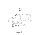
- FIG. 4 shows the sealing element 50 which is injected into the cavity between the housing elements and the cable 20.
- the sealing element 50 is formed in one piece and completely fills the cavity between the first housing element 30, the second housing element 40 and the cable 20.
- the sealing element 50 has a conical section 51 which is formed at the end of the protective device opposite the plug connector 10 and which has a cable entry for the cable 20.
- a sealing ring 52 of the sealing element 50 the outer circumference of the sealing element 50 widens almost to the outer circumference of the protective device.
- An adjoining the sealing ring 52 in the insertion direction cable enclosure 53 is as essentially cylindrical region is formed radially around the cable 20.
- the sealing element 50 merges into an intermediate region 54, which is arranged between the first housing element 30 and the second housing element 40.
- the webs 55 are formed during injection of the sealing element 50 within the injection holes 46 of the second housing member 40.
- the sealing element 50 is formed as a one-piece casting.
- the material of the sealing element 50 is liquid injected into the cavity between the first housing member 30, the second housing member 40 and the cable 20, wherein a cohesive or intimate connection with these is produced by cooling and / or curing of the material of the sealing element.
- the rotary ring 42 remains free of contact with the sealing element 50 and thus rotatable.
- the protection device remains on andWhenckbar in a socket.
- the first housing element 30 and the second housing element 40 are fixed relative to one another until the sealing element 50 has hardened.
- the first housing element 30 fixes the connector 10
- the second housing element 40 fixes the section of the cable 20 facing the connector 10.
- gripping tools can be provided which attach to the two housing elements 30, 40 and / or the cable 20 in order to fix them in their position relative to one another when injecting the sealing element 50.
- the two housing elements 30, 40 and the cable can already be fixed by their coupling, in order to allow injection and curing of the sealing element without "shaking".
- FIGS. 5A and 5B show in two sectional views in each case a section through in the Fig. 1 shown protection device with plug and cable.
- the two cutting planes are perpendicular to each other.
- the sealing element 50 is shown hatched. A synopsis of FIGS. 4 and 5 shows an embodiment of the sealing element 50.
- FIGS. 5A and 5B show further details of the protection device.
- the connector 10 is electrically and mechanically connected to the cable 20 via electrical leads 21.
- An axial direction AR of the cable 20 is also shown.
- the first housing member 30, the second housing member 40 and the sealing member 50 protect the electrical and mechanical connection between the cable 20 and the connector 10 against environmental influences such as water, dust, etc. In addition, a complete shock protection of the connection between the connector 10 and the cable 20 provided by the protection device.
- the cable portion 43 of the second housing member 40 which encloses a portion of the cable 20, terminates in the insertion direction of the connector 10 in front of a stripped portion of the cable 20, from which the electrical leads 21 for contacting the connector 10 protrude.
- the insertion direction may be parallel to the axial direction AR. This prevents the material of the sealing element 50 in the liquid, hot state contacts the contacts in the region between the connector 10 and cable 20.
- the material of the sealing member 50 is prevented in its liquid phase by the cable portion 43 of the first housing member 30 from filling the contact area.
- the contact region between the plug connector 10 and the electrical leads 21 remains substantially free of the sealing element 50.
- substantially free means that no electrical component or semiconductor component, which is arranged on the contact region, passes through the sealing element 50 is mechanically contacted.
- the levers 35 of the first housing member 30 are formed as a spring tongue and made of a metal sheet.
- the lever 35 has substantially in a central portion a tab 36 which is insertable into a corresponding slot of the first housing member 30 to attach the lever 35 to an outer periphery of the first housing member 30. Since the lever 35 is made of a resilient sheet metal, a spring-loaded lever 35 is provided in this way. For example, if pressure is exerted radially on the grip elements 37 of the lever 35 from the outside, an engagement section 38 of the lever 35 is pushed away radially outwards (for the engagement section 38 cf. Fig. 2 ).
- the engagement portion 38 is preferably rectangular.
- a socket in which the plug connector 10 can be inserted has a pair of engagement elements which can be inserted or clipped into the engagement sections 38 of the levers 35 as latching lugs. As a result, the protective device can be connected to the socket or the socket.
- the first housing member 30 further includes a sealing lip 31 to provide a moisture-tight seal between the protector and the socket.
- the sealing lip 31 is preferably made of Viton, silicone rubber or other suitable material and has a plurality of radial waves that increase the elastic malleability in the insertion direction.
- the rotary ring 42 may be formed as part of the second housing member 40, as a separate component or as part of the first housing member 30.
- the rotary ring 42nd together with its insertion sections 41 and the levers 35 serves to make contact with the protective device with the (not shown in the figures) socket or socket.
- Connectors 11 contact area 20 electric wire 21 electrical line 30 first housing element 31 sealing lip 32 section 33 cylindrical section 34 paragraph 36 flap 37 handle element 38 engaging portion 40 second housing element 41 insertion 42 rotating ring 43 cable section 44 cavity portion 45 attack 46 spiracle 47 coupling section 50 sealing element 51 conical section 52 you ring 53 cable inclusion 54 intermediate area 55 web AR axial direction
Landscapes
- Connector Housings Or Holding Contact Members (AREA)
Applications Claiming Priority (1)
| Application Number | Priority Date | Filing Date | Title |
|---|---|---|---|
| DE102012008145.6A DE102012008145B4 (de) | 2012-04-24 | 2012-04-24 | Schutzvorrichtung und Verfahren zur Herstellung einer Schutzvorrichtung |
Publications (2)
| Publication Number | Publication Date |
|---|---|
| EP2658038A1 true EP2658038A1 (fr) | 2013-10-30 |
| EP2658038B1 EP2658038B1 (fr) | 2020-03-04 |
Family
ID=48190012
Family Applications (1)
| Application Number | Title | Priority Date | Filing Date |
|---|---|---|---|
| EP13001985.4A Active EP2658038B1 (fr) | 2012-04-24 | 2013-04-16 | Dispositif de protection et procédé de fabrication d'un dispositif de protection |
Country Status (2)
| Country | Link |
|---|---|
| EP (1) | EP2658038B1 (fr) |
| DE (1) | DE102012008145B4 (fr) |
Families Citing this family (1)
| Publication number | Priority date | Publication date | Assignee | Title |
|---|---|---|---|---|
| DE102016223257A1 (de) | 2016-11-24 | 2018-05-24 | Robert Bosch Gmbh | Temperiereinrichtung, Tankeinrichtung und Verfahren zur Herstellung |
Citations (5)
| Publication number | Priority date | Publication date | Assignee | Title |
|---|---|---|---|---|
| WO2002071548A2 (fr) * | 2001-03-05 | 2002-09-12 | Siemens Aktiengesellschaft | Dispositif pour augmenter le degre de protection |
| DE102005022118A1 (de) * | 2004-05-13 | 2005-12-08 | Yazaki Corp. | Wasserdichte Steckverbindung |
| EP1760838A1 (fr) * | 2005-08-30 | 2007-03-07 | Kostal Kontakt Systeme GmbH | Partie de connecteur électrique |
| US7201595B1 (en) * | 2006-01-06 | 2007-04-10 | Delphi Technologies, Inc. | Electrical connector body co-molded with cable and peripheral seals |
| DE102007004900A1 (de) | 2007-01-31 | 2008-08-14 | Yamaichi Electronics Deutschland Gmbh | Schutzvorrichtung für eine Steckverbindung |
Family Cites Families (6)
| Publication number | Priority date | Publication date | Assignee | Title |
|---|---|---|---|---|
| US6361342B1 (en) * | 2000-09-11 | 2002-03-26 | Baker Hughes Incorporated | Pothead with pressure energized lip seals |
| DE10058265C1 (de) * | 2000-11-23 | 2002-06-13 | Dbt Automation Gmbh Essen | Kabelstecker für elektrische Kabelverbindungen |
| US6648686B2 (en) * | 2000-11-30 | 2003-11-18 | Shimano Inc. | Electrical connector |
| DE202006009187U1 (de) * | 2006-04-22 | 2007-08-30 | Weidmüller Interface GmbH & Co. KG | Adaptergehäuse zur Aufnahme eines Stecker- oder Buchsenteiles |
| DE102007008740B3 (de) * | 2007-02-22 | 2008-07-24 | Siemens Ag | Elektrischer Verbinder mit Spike-Schutz und Verfahren zur Herstellung eines Spike-Schutzes für elektrische Verbinder |
| US7927150B2 (en) * | 2008-10-23 | 2011-04-19 | Tyco Electronics Corporation | Connectors including spring tabs for holding a contact module |
-
2012
- 2012-04-24 DE DE102012008145.6A patent/DE102012008145B4/de active Active
-
2013
- 2013-04-16 EP EP13001985.4A patent/EP2658038B1/fr active Active
Patent Citations (5)
| Publication number | Priority date | Publication date | Assignee | Title |
|---|---|---|---|---|
| WO2002071548A2 (fr) * | 2001-03-05 | 2002-09-12 | Siemens Aktiengesellschaft | Dispositif pour augmenter le degre de protection |
| DE102005022118A1 (de) * | 2004-05-13 | 2005-12-08 | Yazaki Corp. | Wasserdichte Steckverbindung |
| EP1760838A1 (fr) * | 2005-08-30 | 2007-03-07 | Kostal Kontakt Systeme GmbH | Partie de connecteur électrique |
| US7201595B1 (en) * | 2006-01-06 | 2007-04-10 | Delphi Technologies, Inc. | Electrical connector body co-molded with cable and peripheral seals |
| DE102007004900A1 (de) | 2007-01-31 | 2008-08-14 | Yamaichi Electronics Deutschland Gmbh | Schutzvorrichtung für eine Steckverbindung |
Also Published As
| Publication number | Publication date |
|---|---|
| DE102012008145B4 (de) | 2018-01-25 |
| EP2658038B1 (fr) | 2020-03-04 |
| DE102012008145A1 (de) | 2013-10-24 |
Similar Documents
| Publication | Publication Date | Title |
|---|---|---|
| EP3516741B1 (fr) | Connecteur doté d'une protection | |
| DE112013003098T5 (de) | Verbinder und Einspritzverfahren für Füllmaterial | |
| DE202015009708U1 (de) | Steckverbinder und Stecksystem | |
| DE102010022690A1 (de) | Elektrischer Steckverbinder mit PE-Kontakt | |
| DE102018126448A1 (de) | Elektrischer Steckverbinder und elektrische Steckverbindung | |
| EP3352309B1 (fr) | Connecteur enfichable étanche | |
| EP2658038B1 (fr) | Dispositif de protection et procédé de fabrication d'un dispositif de protection | |
| EP2719020B1 (fr) | Élément à emmanchement direct à contact direct protégé | |
| DE102011052364B3 (de) | Steckverbinder für elektrische Komponenten in Kraftfahrzeugen | |
| DE102017001493B4 (de) | Rundsteckverbinder | |
| DE102008031085A1 (de) | Kupplungsteil für eine elektrische Leitung | |
| WO2018024285A1 (fr) | Connecteur de cables | |
| EP2337161A1 (fr) | Agencement de prise et dispositif d'étanchéification pour au moins une ligne, notamment une ligne électrique | |
| EP2648285B1 (fr) | Connecteur enfichable destiné à être monté dans une ouverture de boîtier | |
| WO2016110279A1 (fr) | Connecteur encartable | |
| DE202011105202U1 (de) | Elektrischer Steckverbinder | |
| EP3588695B1 (fr) | Connecteur enfichable à circuit électronique et sa méthode de fabrication | |
| DE102015220685A1 (de) | Zugentlastungselement für eine Leitung, Aufnahmeeinrichtung, Zugentlastungsvorrichtung und Gehäuse | |
| DE102016215641A1 (de) | Steckverbinder für eine elektrische Steckverbindung und Verfahren zur Herstellung eines Steckverbinders | |
| DE202016106514U1 (de) | Entrastsichere elektrische Steckverbindung mit einer elektrischen Steckverbindung und einer elektrischen Buchse | |
| EP3362869B1 (fr) | Agencement comportant un appareil électrique et un câble de connexion | |
| WO2020208075A1 (fr) | Fiche de décharge pour un accumulateur d'une bicyclette électrique | |
| EP4066328B1 (fr) | Ensemble connecteur, connecteur pour un tel ensemble connecteur et procédé d'installation de l'ensemble connecteur | |
| DE202010016711U1 (de) | Anschlussvorrichtung mit Ferring zur Kontaktkrafterzeugung | |
| DE102011055581A1 (de) | Kontakteinsatz für eine Anhängersteckdose |
Legal Events
| Date | Code | Title | Description |
|---|---|---|---|
| PUAI | Public reference made under article 153(3) epc to a published international application that has entered the european phase |
Free format text: ORIGINAL CODE: 0009012 |
|
| AK | Designated contracting states |
Kind code of ref document: A1 Designated state(s): AL AT BE BG CH CY CZ DE DK EE ES FI FR GB GR HR HU IE IS IT LI LT LU LV MC MK MT NL NO PL PT RO RS SE SI SK SM TR |
|
| AX | Request for extension of the european patent |
Extension state: BA ME |
|
| 17P | Request for examination filed |
Effective date: 20140410 |
|
| RBV | Designated contracting states (corrected) |
Designated state(s): AL AT BE BG CH CY CZ DE DK EE ES FI FR GB GR HR HU IE IS IT LI LT LU LV MC MK MT NL NO PL PT RO RS SE SI SK SM TR |
|
| STAA | Information on the status of an ep patent application or granted ep patent |
Free format text: STATUS: EXAMINATION IS IN PROGRESS |
|
| 17Q | First examination report despatched |
Effective date: 20171004 |
|
| GRAP | Despatch of communication of intention to grant a patent |
Free format text: ORIGINAL CODE: EPIDOSNIGR1 |
|
| STAA | Information on the status of an ep patent application or granted ep patent |
Free format text: STATUS: GRANT OF PATENT IS INTENDED |
|
| INTG | Intention to grant announced |
Effective date: 20190925 |
|
| GRAS | Grant fee paid |
Free format text: ORIGINAL CODE: EPIDOSNIGR3 |
|
| GRAA | (expected) grant |
Free format text: ORIGINAL CODE: 0009210 |
|
| STAA | Information on the status of an ep patent application or granted ep patent |
Free format text: STATUS: THE PATENT HAS BEEN GRANTED |
|
| AK | Designated contracting states |
Kind code of ref document: B1 Designated state(s): AL AT BE BG CH CY CZ DE DK EE ES FI FR GB GR HR HU IE IS IT LI LT LU LV MC MK MT NL NO PL PT RO RS SE SI SK SM TR |
|
| REG | Reference to a national code |
Ref country code: GB Ref legal event code: FG4D Free format text: NOT ENGLISH |
|
| REG | Reference to a national code |
Ref country code: CH Ref legal event code: EP |
|
| REG | Reference to a national code |
Ref country code: AT Ref legal event code: REF Ref document number: 1241461 Country of ref document: AT Kind code of ref document: T Effective date: 20200315 |
|
| REG | Reference to a national code |
Ref country code: DE Ref legal event code: R096 Ref document number: 502013014363 Country of ref document: DE |
|
| REG | Reference to a national code |
Ref country code: IE Ref legal event code: FG4D Free format text: LANGUAGE OF EP DOCUMENT: GERMAN |
|
| PG25 | Lapsed in a contracting state [announced via postgrant information from national office to epo] |
Ref country code: FI Free format text: LAPSE BECAUSE OF FAILURE TO SUBMIT A TRANSLATION OF THE DESCRIPTION OR TO PAY THE FEE WITHIN THE PRESCRIBED TIME-LIMIT Effective date: 20200304 Ref country code: NO Free format text: LAPSE BECAUSE OF FAILURE TO SUBMIT A TRANSLATION OF THE DESCRIPTION OR TO PAY THE FEE WITHIN THE PRESCRIBED TIME-LIMIT Effective date: 20200604 Ref country code: RS Free format text: LAPSE BECAUSE OF FAILURE TO SUBMIT A TRANSLATION OF THE DESCRIPTION OR TO PAY THE FEE WITHIN THE PRESCRIBED TIME-LIMIT Effective date: 20200304 |
|
| REG | Reference to a national code |
Ref country code: NL Ref legal event code: MP Effective date: 20200304 |
|
| PG25 | Lapsed in a contracting state [announced via postgrant information from national office to epo] |
Ref country code: BG Free format text: LAPSE BECAUSE OF FAILURE TO SUBMIT A TRANSLATION OF THE DESCRIPTION OR TO PAY THE FEE WITHIN THE PRESCRIBED TIME-LIMIT Effective date: 20200604 Ref country code: GR Free format text: LAPSE BECAUSE OF FAILURE TO SUBMIT A TRANSLATION OF THE DESCRIPTION OR TO PAY THE FEE WITHIN THE PRESCRIBED TIME-LIMIT Effective date: 20200605 Ref country code: SE Free format text: LAPSE BECAUSE OF FAILURE TO SUBMIT A TRANSLATION OF THE DESCRIPTION OR TO PAY THE FEE WITHIN THE PRESCRIBED TIME-LIMIT Effective date: 20200304 Ref country code: LV Free format text: LAPSE BECAUSE OF FAILURE TO SUBMIT A TRANSLATION OF THE DESCRIPTION OR TO PAY THE FEE WITHIN THE PRESCRIBED TIME-LIMIT Effective date: 20200304 Ref country code: HR Free format text: LAPSE BECAUSE OF FAILURE TO SUBMIT A TRANSLATION OF THE DESCRIPTION OR TO PAY THE FEE WITHIN THE PRESCRIBED TIME-LIMIT Effective date: 20200304 |
|
| REG | Reference to a national code |
Ref country code: LT Ref legal event code: MG4D |
|
| PG25 | Lapsed in a contracting state [announced via postgrant information from national office to epo] |
Ref country code: NL Free format text: LAPSE BECAUSE OF FAILURE TO SUBMIT A TRANSLATION OF THE DESCRIPTION OR TO PAY THE FEE WITHIN THE PRESCRIBED TIME-LIMIT Effective date: 20200304 |
|
| PG25 | Lapsed in a contracting state [announced via postgrant information from national office to epo] |
Ref country code: LT Free format text: LAPSE BECAUSE OF FAILURE TO SUBMIT A TRANSLATION OF THE DESCRIPTION OR TO PAY THE FEE WITHIN THE PRESCRIBED TIME-LIMIT Effective date: 20200304 Ref country code: ES Free format text: LAPSE BECAUSE OF FAILURE TO SUBMIT A TRANSLATION OF THE DESCRIPTION OR TO PAY THE FEE WITHIN THE PRESCRIBED TIME-LIMIT Effective date: 20200304 Ref country code: IS Free format text: LAPSE BECAUSE OF FAILURE TO SUBMIT A TRANSLATION OF THE DESCRIPTION OR TO PAY THE FEE WITHIN THE PRESCRIBED TIME-LIMIT Effective date: 20200704 Ref country code: RO Free format text: LAPSE BECAUSE OF FAILURE TO SUBMIT A TRANSLATION OF THE DESCRIPTION OR TO PAY THE FEE WITHIN THE PRESCRIBED TIME-LIMIT Effective date: 20200304 Ref country code: SK Free format text: LAPSE BECAUSE OF FAILURE TO SUBMIT A TRANSLATION OF THE DESCRIPTION OR TO PAY THE FEE WITHIN THE PRESCRIBED TIME-LIMIT Effective date: 20200304 Ref country code: CZ Free format text: LAPSE BECAUSE OF FAILURE TO SUBMIT A TRANSLATION OF THE DESCRIPTION OR TO PAY THE FEE WITHIN THE PRESCRIBED TIME-LIMIT Effective date: 20200304 Ref country code: EE Free format text: LAPSE BECAUSE OF FAILURE TO SUBMIT A TRANSLATION OF THE DESCRIPTION OR TO PAY THE FEE WITHIN THE PRESCRIBED TIME-LIMIT Effective date: 20200304 Ref country code: PT Free format text: LAPSE BECAUSE OF FAILURE TO SUBMIT A TRANSLATION OF THE DESCRIPTION OR TO PAY THE FEE WITHIN THE PRESCRIBED TIME-LIMIT Effective date: 20200729 Ref country code: SM Free format text: LAPSE BECAUSE OF FAILURE TO SUBMIT A TRANSLATION OF THE DESCRIPTION OR TO PAY THE FEE WITHIN THE PRESCRIBED TIME-LIMIT Effective date: 20200304 |
|
| REG | Reference to a national code |
Ref country code: CH Ref legal event code: PL |
|
| REG | Reference to a national code |
Ref country code: DE Ref legal event code: R097 Ref document number: 502013014363 Country of ref document: DE |
|
| PG25 | Lapsed in a contracting state [announced via postgrant information from national office to epo] |
Ref country code: MC Free format text: LAPSE BECAUSE OF FAILURE TO SUBMIT A TRANSLATION OF THE DESCRIPTION OR TO PAY THE FEE WITHIN THE PRESCRIBED TIME-LIMIT Effective date: 20200304 |
|
| PLBE | No opposition filed within time limit |
Free format text: ORIGINAL CODE: 0009261 |
|
| STAA | Information on the status of an ep patent application or granted ep patent |
Free format text: STATUS: NO OPPOSITION FILED WITHIN TIME LIMIT |
|
| PG25 | Lapsed in a contracting state [announced via postgrant information from national office to epo] |
Ref country code: IT Free format text: LAPSE BECAUSE OF FAILURE TO SUBMIT A TRANSLATION OF THE DESCRIPTION OR TO PAY THE FEE WITHIN THE PRESCRIBED TIME-LIMIT Effective date: 20200304 Ref country code: LI Free format text: LAPSE BECAUSE OF NON-PAYMENT OF DUE FEES Effective date: 20200430 Ref country code: CH Free format text: LAPSE BECAUSE OF NON-PAYMENT OF DUE FEES Effective date: 20200430 Ref country code: DK Free format text: LAPSE BECAUSE OF FAILURE TO SUBMIT A TRANSLATION OF THE DESCRIPTION OR TO PAY THE FEE WITHIN THE PRESCRIBED TIME-LIMIT Effective date: 20200304 Ref country code: LU Free format text: LAPSE BECAUSE OF NON-PAYMENT OF DUE FEES Effective date: 20200416 |
|
| REG | Reference to a national code |
Ref country code: BE Ref legal event code: MM Effective date: 20200430 |
|
| 26N | No opposition filed |
Effective date: 20201207 |
|
| PG25 | Lapsed in a contracting state [announced via postgrant information from national office to epo] |
Ref country code: SI Free format text: LAPSE BECAUSE OF FAILURE TO SUBMIT A TRANSLATION OF THE DESCRIPTION OR TO PAY THE FEE WITHIN THE PRESCRIBED TIME-LIMIT Effective date: 20200304 Ref country code: PL Free format text: LAPSE BECAUSE OF FAILURE TO SUBMIT A TRANSLATION OF THE DESCRIPTION OR TO PAY THE FEE WITHIN THE PRESCRIBED TIME-LIMIT Effective date: 20200304 Ref country code: BE Free format text: LAPSE BECAUSE OF NON-PAYMENT OF DUE FEES Effective date: 20200430 |
|
| PG25 | Lapsed in a contracting state [announced via postgrant information from national office to epo] |
Ref country code: IE Free format text: LAPSE BECAUSE OF NON-PAYMENT OF DUE FEES Effective date: 20200416 |
|
| REG | Reference to a national code |
Ref country code: AT Ref legal event code: MM01 Ref document number: 1241461 Country of ref document: AT Kind code of ref document: T Effective date: 20200416 |
|
| PG25 | Lapsed in a contracting state [announced via postgrant information from national office to epo] |
Ref country code: AT Free format text: LAPSE BECAUSE OF NON-PAYMENT OF DUE FEES Effective date: 20200416 |
|
| PG25 | Lapsed in a contracting state [announced via postgrant information from national office to epo] |
Ref country code: TR Free format text: LAPSE BECAUSE OF FAILURE TO SUBMIT A TRANSLATION OF THE DESCRIPTION OR TO PAY THE FEE WITHIN THE PRESCRIBED TIME-LIMIT Effective date: 20200304 Ref country code: MT Free format text: LAPSE BECAUSE OF FAILURE TO SUBMIT A TRANSLATION OF THE DESCRIPTION OR TO PAY THE FEE WITHIN THE PRESCRIBED TIME-LIMIT Effective date: 20200304 Ref country code: CY Free format text: LAPSE BECAUSE OF FAILURE TO SUBMIT A TRANSLATION OF THE DESCRIPTION OR TO PAY THE FEE WITHIN THE PRESCRIBED TIME-LIMIT Effective date: 20200304 |
|
| PG25 | Lapsed in a contracting state [announced via postgrant information from national office to epo] |
Ref country code: MK Free format text: LAPSE BECAUSE OF FAILURE TO SUBMIT A TRANSLATION OF THE DESCRIPTION OR TO PAY THE FEE WITHIN THE PRESCRIBED TIME-LIMIT Effective date: 20200304 Ref country code: AL Free format text: LAPSE BECAUSE OF FAILURE TO SUBMIT A TRANSLATION OF THE DESCRIPTION OR TO PAY THE FEE WITHIN THE PRESCRIBED TIME-LIMIT Effective date: 20200304 |
|
| PGFP | Annual fee paid to national office [announced via postgrant information from national office to epo] |
Ref country code: DE Payment date: 20250429 Year of fee payment: 13 |
|
| PGFP | Annual fee paid to national office [announced via postgrant information from national office to epo] |
Ref country code: FR Payment date: 20250429 Year of fee payment: 13 |
|
| PGFP | Annual fee paid to national office [announced via postgrant information from national office to epo] |
Ref country code: GB Payment date: 20260326 Year of fee payment: 14 |