EP2658040A1 - Stecker mit einer Zugentlastung - Google Patents
Stecker mit einer Zugentlastung Download PDFInfo
- Publication number
- EP2658040A1 EP2658040A1 EP13002084.5A EP13002084A EP2658040A1 EP 2658040 A1 EP2658040 A1 EP 2658040A1 EP 13002084 A EP13002084 A EP 13002084A EP 2658040 A1 EP2658040 A1 EP 2658040A1
- Authority
- EP
- European Patent Office
- Prior art keywords
- cable
- cap
- connector
- plug
- clip
- Prior art date
- Legal status (The legal status is an assumption and is not a legal conclusion. Google has not performed a legal analysis and makes no representation as to the accuracy of the status listed.)
- Granted
Links
Images



Classifications
-
- H—ELECTRICITY
- H01—ELECTRIC ELEMENTS
- H01R—ELECTRICALLY-CONDUCTIVE CONNECTIONS; STRUCTURAL ASSOCIATIONS OF A PLURALITY OF MUTUALLY-INSULATED ELECTRICAL CONNECTING ELEMENTS; COUPLING DEVICES; CURRENT COLLECTORS
- H01R13/00—Details of coupling devices of the kinds covered by groups H01R12/70 or H01R24/00 - H01R33/00
- H01R13/58—Means for relieving strain on wire connection, e.g. cord grip, for avoiding loosening of connections between wires and terminals within a coupling device terminating a cable
- H01R13/5804—Means for relieving strain on wire connection, e.g. cord grip, for avoiding loosening of connections between wires and terminals within a coupling device terminating a cable comprising a separate cable clamping part
- H01R13/5812—Means for relieving strain on wire connection, e.g. cord grip, for avoiding loosening of connections between wires and terminals within a coupling device terminating a cable comprising a separate cable clamping part the cable clamping being achieved by mounting the separate part on the housing of the coupling device
-
- H—ELECTRICITY
- H01—ELECTRIC ELEMENTS
- H01R—ELECTRICALLY-CONDUCTIVE CONNECTIONS; STRUCTURAL ASSOCIATIONS OF A PLURALITY OF MUTUALLY-INSULATED ELECTRICAL CONNECTING ELEMENTS; COUPLING DEVICES; CURRENT COLLECTORS
- H01R13/00—Details of coupling devices of the kinds covered by groups H01R12/70 or H01R24/00 - H01R33/00
- H01R13/58—Means for relieving strain on wire connection, e.g. cord grip, for avoiding loosening of connections between wires and terminals within a coupling device terminating a cable
- H01R13/5804—Means for relieving strain on wire connection, e.g. cord grip, for avoiding loosening of connections between wires and terminals within a coupling device terminating a cable comprising a separate cable clamping part
- H01R13/5816—Means for relieving strain on wire connection, e.g. cord grip, for avoiding loosening of connections between wires and terminals within a coupling device terminating a cable comprising a separate cable clamping part for cables passing through an aperture in a housing wall, the separate part being captured between cable and contour of aperture
-
- H—ELECTRICITY
- H01—ELECTRIC ELEMENTS
- H01R—ELECTRICALLY-CONDUCTIVE CONNECTIONS; STRUCTURAL ASSOCIATIONS OF A PLURALITY OF MUTUALLY-INSULATED ELECTRICAL CONNECTING ELEMENTS; COUPLING DEVICES; CURRENT COLLECTORS
- H01R13/00—Details of coupling devices of the kinds covered by groups H01R12/70 or H01R24/00 - H01R33/00
- H01R13/46—Bases; Cases
- H01R13/502—Bases; Cases composed of different pieces
- H01R13/506—Bases; Cases composed of different pieces assembled by snap action of the parts
-
- H—ELECTRICITY
- H01—ELECTRIC ELEMENTS
- H01R—ELECTRICALLY-CONDUCTIVE CONNECTIONS; STRUCTURAL ASSOCIATIONS OF A PLURALITY OF MUTUALLY-INSULATED ELECTRICAL CONNECTING ELEMENTS; COUPLING DEVICES; CURRENT COLLECTORS
- H01R24/00—Two-part coupling devices, or either of their cooperating parts, characterised by their overall structure
- H01R24/60—Contacts spaced along planar side wall transverse to longitudinal axis of engagement
- H01R24/62—Sliding engagements with one side only, e.g. modular jack coupling devices
- H01R24/64—Sliding engagements with one side only, e.g. modular jack coupling devices for high frequency, e.g. RJ 45
Definitions
- the invention relates to a plug.
- a plug regularly has a connector or plug head, which serves to connect the plug to a socket or socket.
- the connector is connected to a cable, which usually consists of one or more electrical lines or lines and is surrounded by insulation, which may consist of an elastic polymer.
- the electrical wires of the cable are contacted with corresponding terminals in the connector.
- the electrical wires are connected to corresponding terminals in the socket.
- connection between the cable and the connector is claimed both when plugging and unplugging the plug and in the plugged operation at a tensile load on the cable.
- the connection between the cable and the connector is aimed primarily at the electrical contact between the cables in the cable and the corresponding contact points in the connector.
- the invention has for its object to provide a connector with a strain relief, which reduces the above problems.
- a plug has a connector to it is provided and adapted to plug the plug into a socket or a socket. Furthermore, the plug has a cable which is connected to the connector.
- a clip has at least one connecting element for connecting the clip to the connector, and at least one clamping element for producing a clamping connection of the clip to the cable.
- the plug has a cap which, in an installation position, at least partially surrounds the clip so that the cap both fixes the connecting element in a receptacle of the connector and fixes the clamping element in a clamping connection with the cable.
- the installation position of the plug is the position in which the components of the plug, namely connectors, cables, clamps and caps, are fixed together in use position. In the installation position, the strain relief is provided and the plug can be used with a reduced risk of breakage between the cable and the connector.
- the plug may consist of several individual parts that can be assembled, put together, screwed together and / or otherwise connected to each other. When not yet connected, the individual parts of the plug are not in the installation position.
- the clip is preferably formed of a stable material that resists elastic deformation.
- the clip may have a plurality of connecting elements and / or clamping elements which improves both the connection of the clip to the connector and the clamp connection of the clip to the cable.
- the cap In the installation position, the cap includes the bracket at least partially.
- the cap acts on the outside of the clip so that the connecting element of the clip is held in a receptacle of the connector.
- the cap prevents leakage of the connecting element from the receptacle of the connector.
- the cap acts from the outside on the clamping element of the clip, that the clip is held in clamping connection with the cable.
- the cap can act on the clamping element from the outside radially to the central axis of the cable. In particular, in the installation position, a mechanical force can be provided from the cap to the clamping element.
- the clamp has a ring portion which surrounds the cable and which is designed to be displaceable relative to the cable against and in cable propagation direction.
- the annular central axis of the ring section substantially coincides with the central axis of the cable.
- the connecting element from the ring portion facing the connector and having an engagement portion which engages in the installation position in the receptacle of the connector As a result of the displaceable design of the clip, the clip can be pushed in the cable propagation direction as far as the plug connector so that the engagement section engages in the receptacle of the plug connector.
- the engagement portion may be hook-shaped, so that the engagement portion in installation position in the receptacle of the connector hooked. The engagement portion may be held by the cap in the receptacle.
- the clamping element has a hook portion, which is pressed in the installation position of the cap in the cable. As a result, the cap fixes the clip in clamping connection with the cable.
- the cap is substantially cylindrical, wherein the cylinder axis of the cap substantially coincides with the central axis of the cable.
- the cap may have the shape of a hollow cylinder, wherein the volume of the hollow interior is adapted to the size of the clip such that the cap is slidable over the clip and is in installation position in mechanical contact with the clip.
- the cap is displaceable relative to the cable when the plug is not in installation position. In installation position, all components of the connector are fixed relative to each other. Due to the displaceable design of the cap, the cap can be pushed over the clip so that both the cap and the clip are fixed in the installation position.
- the cap has a conical portion which presses in the installation position from the outside on the clamping element, that the clamping element provides a clamping connection between the clamp and the cable. From the outside, this means radially inward to the cable.
- the conical section has a distance between the cap and the cable, which decreases substantially steadily. In the installation position, the cap with the narrowing conical section is pushed onto the clamping element so far that the clamping element is pressed towards the cable.
- the clamping element is elastically deformable, so that it is bendable in the direction of the cable.
- the clip has at least one latching element and the Cap on at least one locking portion for locking the cap with the clip.
- This provides a latching connection between the clip and the cap.
- the locking connection serves to fix the cap relative to the clip. In particular, the cap is locked in the installation position with the clip.
- the latching connection holds the cap so in the installation position that the cap fixes both the connecting element in the receptacle of the connector and the clamping element in clamping connection with the cable.
- the locking connection may be formed so that the latching connection counteracts a displacement of the cap relative to the cable in the direction away from the connector.
- the connecting element and the clamping element are offset relative to one another in the jacket direction of the cable. Even with a plurality of binding elements and clamping elements these are offset in the direction of the cable against each other.
- the offset in the direction of the jacket causes a good distribution of the points of attack both for the connection of the clip to the connector and the clamping connection of the clip to the cable. This distribution of the attack points causes an improved statics and thus a higher load capacity of the train.
- the connecting element engages in the installation position with the connector a positive connection. This can be done for example by a hook-shaped design of the connecting element, which is hooked in the receptacle of the connector.
- the cap exerts a normal force on the clamping element in such a way that a frictional connection between the clamp and the cable is provided.
- the normal force acts from the outside radially to the cable.
- the clamping element can be pressed into the cable.
- the frictional connection is particularly effective when the cable of an elastic layer or insulation is surrounded, such as an elastic material made of polymers.
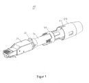
- FIG. 1 shows in a perspective view a plug 10.
- the plug 10 is in Fig. 1 not shown in its installation position, but shortly before assembly in the installation position.
- the plug 10 has a connector 20, a cable 30, a clip 40 and a cap 50.
- the connector 20 is designed as a plug head, which is intended to be connected to a socket or socket.
- the plug 10 is designed as an RJ plug.
- RJ means 'Registered Jack', eg an Ethernet connector.
- the plug may be formed as any other plug that is capable of producing at least one electrical contact between at least one within the cable arranged metallic line with an electrical contact of a socket is used.
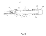
- FIG. 2 shows a sectional view through the in Fig. 1
- the cable 30 has a first cable end 31 which is connected to the plug 20. In this case, the first cable end 31 contacts the connector 20 electrically.
- the connector 20 has a neck portion 22 into which the first cable end 31 is inserted.
- the neck portion 22 is formed substantially annular and serves to receive the cable 30.
- the neck portion 22 has an inner diameter which substantially corresponds to the outer diameter of the cable 30.
- the cable 30 passes through the bracket 40, which as a single component in FIG. 3 is shown.
- the bracket 40 is in the form of a crown having a ring portion 43.
- the annular portion 43 has an inner diameter which is sufficiently large that the cable 30 can be guided through the annular portion 43.
- the cable 30 is laid through the annular portion 43 of the bracket 40 so that the cylinder axis of the annular portion 43 substantially coincides with the central axis of the cable 30.
- the inner diameter of the ring portion 43 is formed so large that the clip 40 is displaceable relative to the threaded through the ring portion 43 cable 30 in the direction of propagation of the cable 30.
- the bracket 40 has four connecting elements 41, which are formed substantially elongated and extending from the ring portion 43 to the connector 20 back.
- the connecting elements 41 contact in the in FIGS. 1 and 2 shown position of the plug 10, the plug head 20 is not yet and are arranged without contact to Halsbabrough 22 of the connector 20.
- two connecting elements 41 are arranged with respect to the cable 30 on opposite sides.
- Each connecting element 41 has an inwardly facing engaging portion 41A.
- the engagement portion 41A is hook-shaped and faces the cable, in particular the cable center axis.
- each connecting element 41 latching elements 41 B, which consist of several, in the propagation direction of the cable one behind the other latching lugs.
- the locking elements 41 B are arranged on each connecting element 41 so that they are opposite to the engaging portion 41 A and facing away from the connecting element 41 to the outside, away from the cable.
- the latching elements can also be arranged at a different position of the clamp.
- the clamp 40 has four clamping elements 42, of which in each case two clamping elements 42 with respect to the cable 30 opposite or are arranged opposite to each other.
- the clamping elements 42 point away from the connector 20 substantially parallel to the cable propagation direction from the ring portion 43.
- the connecting elements 41 and the clamping elements 42 are each elongated and have from the ring portion 43 in opposite directions. This results in the crown shape of the clip 40. Unlike a normal crown, the clip 40 has "crown prongs" not only in one direction, but in two opposing directions.
- the connecting elements 41 and the clamping elements 42 are offset in the direction of the cable 30 or in the ring direction of the ring portion 43 against each other. In the embodiments shown in the figures with four connecting elements and four clamping elements, the connecting elements 41 are offset from the clamping elements 42 by 45 ° to each other.
- the displacement of the connecting elements 41 and the clamping elements 42 in the direction of the cable of the cable is substantially equal to 360 ° divided by the total number of connecting elements and clamping elements.
- Each clamping member 42 has a hook portion 42A formed at the end of the clamping member 42 facing the ring portion 43.
- the hook portions 42A face inward toward the cable 30.
- Both the connecting elements 41 and the clamping elements 42 are formed at the propagation end, which is opposite to the annular portion 43, radially inwardly and / or outwardly movable, so that the hook portions 42 A and the engaging portions 41 B are movable inwardly and / or outwardly.
- the clamping element 40 may be formed of plastic, plastic, metal or a metal alloy.
- the cap 50 is substantially cylindrical in shape and comprises the cable 30.
- the inner diameter of the cap 50 is formed larger than the outer diameter of the cable 30, whereby the cable 30 can be easily inserted into the cap 50.
- a cavity formed between the cable 30 and the cap 50 is formed to receive both the cable 30 and the clip 40.
- the central axis of the cap 50 substantially coincides with the propagation axis of the cable 30.
- the cap 50 is easily displaced relative to the direction of propagation of the cable.
- a latching portion 42 is formed, which faces the cable 30 and is formed as a radially inwardly facing ring.
- the size of the latching portion 52 is matched to the size of the locking elements 41 B.
- the latching portion 52 is located closer to the cylinder end of the cap 50 facing the connector 20 than the opposite end of the cap 50.
- the cap 50 At the end of the cap 50 facing away from the connector 20, the cap 50 has a conical portion 51, at which the inner diameter of the cap 50 narrows counter to the insertion direction of the plug 10.
- FIG. 4 shows the in Fig. 1 shown plug 10 in an installation position.
- the cap 50 is pushed over the bracket 40 in the direction of the connector 20, that the connector 20, the bracket 40, the cap 50 and the cable 30 are fixed relative to each other.
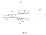
- FIG. 5 shows in a sectional view a sectional view through the plug 10, as shown in FIG Fig. 4 is shown in installation position.
- the latching portion 52 of the cap 50 is latched to the latching elements 41 B of the connecting elements 41.
- the latching connection provides in particular a positive connection against the direction of insertion of the plug 10 ready.
- the cap 40 is arranged with the connecting elements 41 pushed up to the connector 20.
- the engaging portions 41A of the connecting elements 41 are arranged in receptacles 21 of the neck portion 22.
- the receptacles 21 are formed in the neck portion 22 of the connector 20.
- the hook-shaped engagement portions 51 a are arranged in the installation position in the receptacles 21 that opposite to the insertion of the plug 10, a positive connection is provided.
- the cap 50 includes the connecting elements 41 from the outside such that the engaging portions 41 A are fixed in the receptacles 21. A release of the positive connection of the bracket 40 with the connector 20 by a relative movement of the engaging portions 41 A away from the cable to the outside is blocked by the cap 50.
- Fig. 5 It is shown that from the cable interior of the cable 30 to the outside, the cable 30 is at first partially surrounded by the neck portion 22, which is surrounded by the clip 40 (in particular the connecting elements 41 of the bracket 40), which in turn from the outside of the cap 50th are surrounded.
- the clip 40 in particular the connecting elements 41 of the bracket 40
- the bracket 40 By the locking connection between the cap 50 and the clip 40 is a Moving the cap 50 blocked in the propagation direction of the cable away from the connector 20.
- the cap 50 holds the bracket 40 fixed relative to the connector 20.
- FIG. 6 shows in a further sectional view a section through the in Fig. 4 shown plug 10.
- the cutting plane is offset parallel to the cutting plane of the Fig. 5
- the plug 10 is shown in its installation position.
- the conical portion 51 of the cap 50 is pulled in the installation position so far on the bracket 40 that the clamping elements 42 of the bracket 40 abut the conical portion 51.
- the clamping elements 42 are pressed radially inwardly towards the cable 30, in particular, the hook portions 42 A are pressed into an outer insulation of the cable 30.
- the conical portion 51 of the cap 50 causes a radial normal force on the clamping elements 42, which causes a frictional connection between the bracket 40 and the cable 30.
- a strain relief between the connector and the cable is provided via a crown-shaped bracket.
- the cap 50 can be latched on the outside of the clip 40 on the latching elements 41 B.
- the cap 50 also has recesses 53 for latching with the bracket 40.
- the clip 40 is easily displaced, even against the hook direction of the connecting elements 41 and clamping elements 42.
- the clip 40 is first hooked to the connector 20 as a connector. Then, the cap 50 is pushed over the bracket 40, so that the conical portion 51 of the cap 50 presses the clamping elements 42 as claws in the cable 30 until a suitable locking position between the locking elements 41 B and the latching portion 52 is reached.
- the clip 40 is secured to the connector 20 by the cap 50 against opening.
- the plug 10 can be opened more easily.
- At least one of the recesses 53 is used for a nose-groove guide.
- the connector 20 has a groove 23. In installation position, the groove 23 engages in one of the recesses 53 of the cap 50 a.
- the plug 10 can be mounted easily and without special tools. He may be trained and provided to be openable only with the aid of a special tool.
- the clip 40 is further adapted to be usable for a large number of different cable diameters.
Landscapes
- Details Of Connecting Devices For Male And Female Coupling (AREA)
Abstract
Description
- Die Erfindung betrifft einen Stecker.
- Ein Stecker weist regelmäßig einen Steckverbinder oder Steckkopf auf, der zum Verbinden des Steckers mit einer Buchse oder Steckdose dient. Der Steckverbinder ist mit einem Kabel verbunden, das üblicherweise aus einer oder mehreren elektrischen Leitung bzw. Leitungen besteht und von einer Isolierung umgeben ist, die aus einem elastischen Polymer bestehen kann.
- Die elektrischen Leitungen des Kabels werden mit korrespondierenden Anschlüssen im Steckverbinder kontaktiert. Über den Steckverbinder werden die elektrischen Leitungen mit korrespondierenden Anschlüssen in der Buchse verbunden.
- Bei der Verbindung des Kabels mit dem Steckverbinder ergeben sich regelmäßig dadurch Probleme, dass sowohl beim Ein- und Ausstecken des Steckers als auch im eingesteckten Betrieb bei einer Zugbelastung auf das Kabel die Verbindung zwischen dem Kabel und dem Steckverbinder beansprucht wird. Die Verbindung zwischen dem Kabel und dem Steckverbinder zielt in erster Linie auf die elektrische Kontaktierung zwischen den Leitungen im Kabel und den korrespondierenden Kontaktstellen im Steckverbinder ab. Durch mechanische Belastung, insbesondere durch einen Zug am Kabel, kann sowohl die mechanische Verbindung zwischen dem Kabel und dem Stecker als auch die elektrische Kontaktierung unterbrochen werden.
- Der Erfindung liegt die Aufgabe zugrunde, einen Stecker mit einer Zugentlastung bereitzustellen, die die oben genannten Probleme reduziert.
- Gemäß einem Aspekt weist ein Stecker einen Steckverbinder auf, der dazu vorgesehen und ausgebildet ist, den Stecker in eine Buchse oder eine Steckdose einzustecken. Weiterhin weist der Stecker ein Kabel auf, das mit dem Steckverbinder verbunden ist. Eine Klammer weist zumindest ein Verbindungselement zum Verbinden der Klammer mit dem Steckverbinder auf, sowie zumindest ein Klemmelement zum Herstellen einer Klemmverbindung der Klammer mit dem Kabel. Weiterhin weist der Stecker eine Kappe auf, die in einer Installationsposition die Klammer zumindest teilweise so umfasst, dass die Kappe sowohl das Verbindungselement in einer Aufnahme des Steckverbinders fixiert als auch das Klemmelement in einer Klemmverbindung mit dem Kabel fixiert. Durch diesen Stecker wird vom Steckverbinder über das Verbindungselement der Klammer und über das Klemmelement der Klammer eine Zugentlastung zwischen dem Steckverbinder und dem Kabel bereit gestellt. Eine mechanische Belastung, insbesondere eine Zugbelastung des Kabels, beansprucht somit nicht direkt die mechanische und elektrische Verbindung zwischen dem Kabel und dem Steckverbinder, sondern wird vom Kabel über die Klammer in den Steckverbinder geleitet.
- Dabei ist die Installationsposition des Steckers die Position, in der die Bauteile des Steckers, nämlich Steckverbinder, Kabel, Klammer und Kappen, miteinander in Gebrauchsposition fixiert sind. In der Installationsposition ist die Zugentlastung bereitgestellt und der Stecker kann unter einer reduzierten Unterbrechungsgefahr zwischen dem Kabel und dem Steckverbinder verwendet werden. Der Stecker kann aus mehreren Einzelteilen bestehen, die zusammengesetzt, zusammengesteckt, zusammengeschraubt und/oder anders miteinander verbunden werden können. Im noch nicht miteinander verbundenen Zustand befinden sich die Einzelteile des Steckers nicht in der Installationsposition.
- Die Stärke der Zugentlastung wird u. A. bestimmt durch die mechanische Belastbarkeit der Klammer. Deswegen ist die Klammer vorzugsweise aus einem stabilen Material ausgebildet, das einer elastischen Verformung standhält. Anstelle eines einzigen Verbindungselements und/oder eines einzigen Klemmelements kann die Klammer eine Mehrzahl von Verbindungselementen und/oder Klemmelementen aufweisen, was sowohl die Verbindung der Klammer mit dem Steckverbinder als auch die Klemmverbindung der Klammer mit dem Kabel verbessert.
- In der Installationsposition umfasst die Kappe die Klammer zumindest teilweise. Dabei wirkt die Kappe von außen so auf die Klammer ein, dass das Verbindungselement der Klammer in einer Aufnahme des Steckverbinders gehalten wird. Die Kappe verhindert dabei ein Austreten des Verbindungselements aus der Aufnahme des Steckverbinders. Weiterhin wirkt die Kappe von außen so auf das Klemmelement der Klammer ein, dass die Klammer in Klemmverbindung mit dem Kabel gehalten wird. Die Kappe kann dabei von außen radial zur Mittelachse des Kabels auf das Klemmelement einwirken. Insbesondere kann in der Installationsposition eine mechanische Kraft von der Kappe auf das Klemmelement bereitgestellt werden.
- Gemäß einer Ausführungsform weist die Klammer einen Ringabschnitt auf, der das Kabel umgibt und der relativ zum Kabel gegen und in Kabelausbreitungsrichtung verschiebbar ausgebildet ist. Dabei fällt die Ringmittelachse des Ringabschnitts im Wesentlichen mit der Mittelachse des Kabels zusammen. Dadurch, dass die Klammer verschiebbar ausgebildet ist, kann die Position der Klammer relativ zum Kabel und zu dem mit dem Kabel verbundenen Steckverbinder optimal eingestellt werden. Die Klammer ist lediglich so lange verschiebbar, bis der Stecker in seiner Installationsposition zusammengebaut ist. In Installationsposition befindet sich die Klammer in einer Klemmverbindung mit dem Kabel und ist deswegen nicht mehr relativ zum Kabel verschiebbar.
- Dabei kann das Verbindungselement vom Ringabschnitt zum Steckverbinder weisen und einen Eingriffabschnitt aufweisen, der in Installationsposition in die Aufnahme des Steckverbinders eingreift. Durch die verschiebbare Ausbildung der Klammer kann die Klammer in Kabelausbreitungsrichtung soweit zum Steckverbinder geschoben werden, dass der Eingriffabschnitt in die Aufnahme des Steckverbinders eingreift. Der Eingriffabschnitt kann dabei hakenförmig ausgebildet sein, so dass sich der Eingriffabschnitt in Installationsposition in der Aufnahme des Steckverbinders verhakt. Der Eingriffabschnitt kann von der Kappe in der Aufnahme gehalten werden.
- Gemäß einer Ausführungsform weist das Klemmelement einen Hakenabschnitt auf, der in der Installationsposition von der Kappe in das Kabel hineingedrückt ist. Dadurch fixiert die Kappe die Klammer in Klemmverbindung mit dem Kabel.
- Gemäß einer Ausführungsform ist die Kappe im Wesentlichen zylinderförmig ausgebildet, wobei die Zylinderachse der Kappe im Wesentlichen mit der Mittelachse des Kabels zusammenfällt. Insbesondere kann die Kappe die Form eines Hohlzylinders aufweisen, wobei das Volumen des Hohlinnenraumes auf die Größe der Klammer derart abgestimmt ist, dass die Kappe über die Klammer schiebbar ist und in Installationsposition in mechanischem Kontakt mit der Klammer steht.
- Gemäß einer Ausführungsform ist die Kappe relativ zum Kabel verschiebbar, wenn sich der Stecker nicht in Installationsposition befindet. In Installationsposition sind alle Bauelemente des Steckers relativ zueinander fixiert. Durch die verschiebbare Ausbildung der Kappe kann die Kappe so über die Klammer geschoben werden, dass sowohl die Kappe als auch die Klammer in Installationsposition fixiert sind.
- Gemäß einer Ausführungsform weist die Kappe einen konischen Abschnitt auf, der in Installationsposition von außen so auf das Klemmelement drückt, dass das Klemmelement eine Klemmverbindung zwischen der Klammer und dem Kabel bereitstellt. Von außen bedeutet dabei radial nach innen zum Kabel. Der konische Abschnitt weist dabei einen Abstand zwischen der Kappe und dem Kabel auf, der sich im Wesentlichen stetig verringert. In der Installationsposition ist die Kappe mit dem sich verengenden konischen Abschnitt soweit auf das Klemmelement geschoben, dass das Klemmelement zum Kabel hin gedrückt wird.
- Das Klemmelement ist elastisch verformbar ausgebildet, so dass es in Richtung zum Kabel biegbar ausgebildet ist.
- In einer Ausführungsform weist die Klammer zumindest ein Rastelement und die Kappe zumindest einen Rastabschnitt zum Verrasten der Kappe mit der Klammer auf. Dadurch wird eine Rastverbindung zwischen der Klammer und der Kappe bereitgestellt. Die Rastverbindung dient zur Fixierung der Kappe relativ zur Klammer. Insbesondere ist die Kappe in der Installationsposition mit der Klammer verrastet. Die Rastverbindung hält dabei die Kappe so in der Installationsposition, dass die Kappe sowohl das Verbindungselement in der Aufnahme des Steckverbinders fixiert als auch das Klemmelement in Klemmverbindung mit dem Kabel. Die Rastverbindung kann so ausgebildet sein, dass die Rastverbindung einem Verschieben der Kappe relativ zum Kabel in Richtung vom Steckverbinder weg entgegenwirkt.
- Gemäß einer Ausführungsform ist das Verbindungselement und das Klemmelement in Mantelrichtung des Kabels versetzt gegeneinander ausgebildet. Auch bei einer Mehrzahl von Bindungselementen und Klemmelementen sind diese in Mantelrichtung des Kabels versetzt gegeneinander ausgebildet. Die Versetzung in Mantelrichtung bewirkt dabei eine gute Verteilung der Angriffspunkte sowohl für die Verbindung der Klammer mit dem Steckverbinder als auch der Klemmverbindung der Klammer mit dem Kabel. Diese Verteilung der Angriffspunkte bewirkt eine verbesserte Statik und somit eine höhere Belastbarkeit der Zugverbindung.
- Gemäß einer Ausführungsform geht das Verbindungselement in der Installationsposition mit dem Steckverbinder eine formschlüssige Verbindung ein. Dies kann zum Beispiel durch eine hakenförmige Ausbildung des Verbindungselements erfolgen, das in der Aufnahme des Steckverbinders eingehakt wird.
- Gemäß einer Ausführungsform übt die Kappe in der Installationsposition eine Normalkraft auf das Klemmelement derart aus, dass eine kraftschlüssige Verbindung zwischen der Klammer und dem Kabel bereitgestellt wird. Die Normalkraft wirkt dabei von außen radial zum Kabel hin. Durch die Normalkraft kann das Klemmelement in das Kabel hineingedrückt werden. Die kraftschlüssige Verbindung ist besonders effektiv, wenn das Kabel von einer elastischen Schicht bzw. Isolierung umgeben ist, wie zum Beispiel einem elastischen Material aus Polymeren.
- Einzelne Ausführungsformen der Erfindung werden nachfolgend anhand von Figuren näher erläutert. Einzelne Merkmale der in den Figuren gezeigten Ausführungsformen können mit anderen Ausführungsformen kombiniert werden. Es zeigen:
- Fig. 1
- eine perspektivische Ansicht eines Steckers, bevor er in einer Installationsposition zusammengesetzt ist;
- Fig. 2
- eine Schnittdarstellung durch den in
Fig. 1 gezeigten Stecker; - Fig. 3
- eine schematische Ansicht einer Klammer des in
Fig. 1 gezeigten Steckers; - Fig. 4
- eine perspektivische Darstellung des in
Fig. 1 gezeigten Steckers in einer Installationsposition; - Fig. 5
- eine Schnittdarstellung des in
Fig. 4 gezeigten Steckers und - Fig. 6
- eine Schnittdarstellung durch den in
Fig. 4 gezeigten Stecker durch eine Schnittebene, die zu der Schnittebene derFig. 5 parallel versetzt ist. -
Figur 1 zeigt in einer perspektivischen Darstellung einen Stecker 10. Der Stecker 10 ist inFig. 1 nicht in seiner Installationsposition gezeigt, sondern kurz vor dem Zusammenbau in die Installationsposition. - Der Stecker 10 weist einen Steckverbinder 20, ein Kabel 30, eine Klammer 40 und eine Kappe 50 auf. Der Steckverbinder 20 ist als Steckkopf ausgebildet, der dazu vorgesehen ist, mit einer Buchse oder Steckdose verbunden zu werden. In
Fig. 1 ist der Stecker 10 als RJ-Stecker ausgebildet. RJ bedeutet 'Registered Jack', also z.B. ein Ethernet-Stecker. In alternativen Ausführungsformen kann der Stecker als beliebiger anderer Stecker ausgebildet sein, der zum Herstellen zumindest eines elektrischen Kontaktes zwischen zumindest einer innerhalb des Kabels angeordneten metallischen Leitung mit einem elektrischen Kontakt einer Buchse dient. -
Figur 2 zeigt eine Schnittdarstellung durch den inFig. 1 dargestellten Stecker 10. Das Kabel 30 weist ein erstes Kabelende 31 auf, das mit dem Stecker 20 verbunden ist. Dabei kontaktiert das erste Kabelende 31 den Steckverbinder 20 elektrisch. Der Steckverbinder 20 weist einen Halsabschnitt 22 auf, in den das erste Kabelende 31 eingeführt ist. Der Halsabschnitt 22 ist im Wesentlichen ringförmig ausgebildet und dient zur Aufnahme des Kabels 30. Der Halsabschnitt 22 weist einen Innendurchmesser auf, der im Wesentlichen dem Außendurchmesser des Kabels 30 entspricht. - Das Kabel 30 verläuft durch die Klammer 40, die als einzelnes Bauteil in
Figur 3 gezeigt ist. Die Klammer 40 ist in Form einer Krone ausgebildet, die einen Ringabschnitt 43 aufweist. Der Ringabschnitt 43 weist einen Innendurchmesser auf, der ausreichend groß ausgebildet ist, dass das Kabel 30 durch den Ringabschnitt 43 führbar ist. In denFiguren 1 und2 ist das Kabel 30 so durch den Ringabschnitt 43 der Klammer 40 verlegt, dass die Zylinderachse des Ringabschnitts 43 im Wesentlichen mit der Mittelachse des Kabels 30 zusammenfällt. Der Innendurchmesser des Ringabschnitts 43 ist so groß ausgebildet, dass die Klammer 40 relativ zu dem durch den Ringabschnitt 43 gefädelten Kabel 30 in Ausbreitungsrichtung des Kabels 30 verschiebbar ist. - Die Klammer 40 weist vier Verbindungselemente 41 auf, die im Wesentlichen länglich ausgebildet sind und sich vom Ringabschnitt 43 zum Steckverbinder 20 hin erstrecken. Dabei kontaktieren die Verbindungselemente 41 in der in
Figuren 1 und2 dargestellten Position des Steckers 10 den Steckkopf 20 noch nicht und sind kontaktfrei zum Halsbabschnitt 22 des Steckverbinders 20 angeordnet. Jeweils zwei Verbindungselemente 41 sind bezüglich des Kabels 30 an einander gegenüberliegenden Seiten angeordnet. Jedes Verbindungselement 41 weist einen nach innen weisenden Eingriffabschnitt 41A auf. Der Eingriffabschnitt 41A ist hakenförmig ausgebildet und weist zum Kabel, insbesondere zur Kabelmittelachse. Weiterhin weist jedes Verbindungselement 41 Rastelemente 41 B auf, die aus mehreren, in Ausbreitungsrichtung des Kabels hintereinander liegenden Rastnasen bestehen. Die Rastelemente 41 B sind auf jedem Verbindungselement 41 so angeordnet, dass sie dem Eingriffabschnitt 41A gegenüberliegen und vom Verbindungselement 41 aus nach außen, vom Kabel weg weisen. - In einer alternativen Ausführungsform können die Rastelemente auch an einer anderen Position der Klammer angeordnet sein.
- Weiterhin weist die Klammer 40 vier Klemmelemente 42 auf, von denen sich jeweils zwei Klemmelemente 42 bezüglich des Kabels 30 gegenüberliegen bzw. zueinander gegenüberliegend angeordnet sind. Die Klemmelemente 42 weisen vom Ringabschnitt 43 im Wesentlichen parallel zur Kabelausbreitungsrichtung von dem Steckverbinder 20 weg.
- Die Verbindungselemente 41 und die Klemmelemente 42 sind jeweils länglich ausgebildet und weisen vom Ringabschnitt 43 aus in einander gegenüberliegende Richtungen. Dadurch ergibt sich die kronenförmige Form der Klammer 40. Im Unterschied zu einer normalen Krone weist die Klammer 40 "Kronenzacken" nicht nur in einer Richtung auf, sondern in zwei einander gegenüberliegende Richtungen. Die Verbindungselemente 41 und die Klemmelemente 42 sind in Mantelrichtung des Kabels 30 bzw. in Ringrichtung des Ringabschnitts 43 versetzt gegeneinander ausgebildet. In den in den Figuren gezeigten Ausführungsbeispielen mit jeweils vier Verbindungselementen und vier Klemmelementen sind die Verbindungselemente 41 zu den Klemmelementen 42 um jeweils 45° zueinander versetzt.
- Allgemein entspricht die Versetzung der Verbindungselemente 41 und der Klemmelemente 42 in Mantelrichtung des Kabels im Wesentlichen 360° geteilt durch die Gesamtanzahl der Verbindungselemente und Klemmelemente.
- Eine gerade Anzahl von Klemmelementen ist dabei bevorzugt, da durch Paare von bezüglich des Kabels einander gegenüberliegende Klemmelementen eine statisch gute Klemmverbindung herstellbar ist.
- Jedes Klemmelement 42 weist einen Hakenabschnitt 42A auf, der an dem Ende des Klemmelements 42 ausgebildet ist, das dem Ringabschnitt 43 gegenüberliegt. Die Hakenabschnitte 42A weisen nach innen in Richtung zum Kabel 30.
- Sowohl die Verbindungselemente 41 als auch die Klemmelemente 42 sind an dem Ausbreitungsende, das dem Ringabschnitt 43 gegenüberliegt, radial nach innen und/oder außen beweglich ausgebildet, so dass die Hakenabschnitte 42A und die Eingriffabschnitte 41 B nach innen und/oder außen bewegbar sind.
- Das Klemmelement 40 kann aus Plastik, Kunststoff, Metall oder einer Metall-Legierung ausgebildet sein.
-
Figuren 1 und2 zeigen weiterhin die Kappe 50. Die Kappe 50 ist im Wesentlichen zylinderförmig ausgebildet und umfasst das Kabel 30. Der Innendurchmesser der Kappe 50 ist dabei größer als der Außendurchmesser des Kabels 30 ausgebildet, wodurch sich das Kabel 30 leicht in die Kappe 50 einführen läßt. Im Gegensatz zum Durchmesser des Halsabschnitts 22 und dem Innendurchmesser des Ringabschnitts 43 ist zwischen dem Kabel 30 und der Kappe 50 ein Hohlraum ausgebildet, der dazu ausgebildet und vorgesehen ist, sowohl das Kabel 30 als auch die Klammer 40 aufzunehmen. - Die Mittelachse der Kappe 50 fällt im Wesentlichen mit der Ausbreitungsachse des Kabels 30 zusammen. Die Kappe 50 läßt sich leicht relativ zur Ausbreitungsrichtung des Kabels verschieben.
- Auf der Innenseite der Kappe 50 ist ein Rastabschnitt 42 ausgebildet, der zum Kabel 30 weist und als radial nach innen weisender Ring ausgebildet ist. Die Größe des Rastabschnitts 52 ist auf die Größe der Rastelemente 41 B abgestimmt. Der Rastabschnitt 52 ist näher an dem Zylinderende der Kappe 50 angeordnet, das dem Steckverbinder 20 zugewandt ist, als dem gegenüberliegendem Ende der Kappe 50.
- An dem Ende der Kappe 50, das vom Steckverbinder 20 weg weist, weist die Kappe 50 einen konischen Abschnitt 51 auf, an dem sich der Innendurchmesser der Kappe 50 entgegen der Einsteckrichtung des Steckers 10 betrachtet verengt.
-
Figur 4 zeigt den inFig. 1 gezeigten Stecker 10 in einer Installationsposition. In der Installationsposition ist die Kappe 50 so über die Klammer 40 in Richtung zum Steckverbinder 20 geschoben, dass der Steckverbinder 20, die Klammer 40, die Kappe 50 und das Kabel 30 relativ zueinander fixiert sind. -
Figur 5 zeigt in einer Schnittdarstellung eine Schnittansicht durch den Stecker 10, wie er inFig. 4 in Installationsposition gezeigt ist. Dabei ist der Rastabschnitt 52 der Kappe 50 mit den Rastelementen 41 B der Verbindungselemente 41 verrastet. Die Rastverbindung stellt insbesondere eine formschlüssige Verbindung entgegen der Steckrichtung des Steckers 10 bereit. - Die Kappe 40 ist mit den Verbindungselementen 41 bis an den Steckverbinder 20 herangeschoben angeordnet. Dabei sind die Eingriffabschnitte 41A der Verbindungselemente 41 in Aufnahmen 21 des Halsabschnitts 22 angeordnet. Die Aufnahmen 21 sind im Halsabschnitt 22 des Steckverbinders 20 ausgebildet. Die hakenförmigen Eingriffabschnitte 51 a sind in der Installationsposition so in den Aufnahmen 21 angeordnet, dass entgegen der Einsteckrichtung des Steckers 10 eine formschlüssige Verbindung bereitgestellt wird. Dabei umfasst die Kappe 50 die Verbindungselemente 41 von außen derart, dass die Eingriffabschnitte 41A in den Aufnahmen 21 fixiert sind. Ein Lösen der formschlüssigen Verbindung der Klammer 40 mit dem Steckverbinder 20 durch eine Relativbewegung der Eingriffabschnitte 41 A vom Kabel weg nach außen ist durch die Kappe 50 blockiert.
- In
Fig. 5 ist gezeigt, dass vom Kabelinneren des Kabels 30 aus nach außen das Kabel 30 zunächst zumindest teilweise von dem Halsabschnitt 22 umgeben ist, welcher von der Klammer 40 (insbesondere den Verbindungselementen 41 der Klammer 40) umgeben ist, die wiederum von außen von der Kappe 50 umgeben sind. Durch die Rastverbindung zwischen der Kappe 50 und der Klammer 40 wird ein Verschieben der Kappe 50 in Ausbreitungsrichtung des Kabels vom Steckverbinder 20 weg blockiert. Die Kappe 50 ihrerseits hält die Klammer 40 fixiert relativ zum Steckverbinder 20. -
Figur 6 zeigt in einer weiteren Schnittdarstellung einen Schnitt durch den inFig. 4 gezeigten Stecker 10. Die Schnittebene ist parallel versetzt zu der Schnittebene derFig. 5 . InFig. 6 ist der Stecker 10 in seiner Installationsposition gezeigt. Der konische Abschnitt 51 der Kappe 50 ist in Installationsposition soweit auf die Klammer 40 gezogen, dass die Klemmelemente 42 der Klammer 40 an den konischen Abschnitt 51 anstoßen. Dadurch werden die Klemmelemente 42 radial nach innen zum Kabel 30 hin gedrückt, wobei insbesondere die Hakenabschnitte 42A in eine Außenisolierung des Kabels 30 hineingedrückt werden. Dabei entsteht eine Klemmverbindung zwischen der Klammer 40 und dem Kabel 30. Der konische Abschnitt 51 der Kappe 50 bewirkt dabei eine radiale Normalkraft auf die Klemmelemente 42, die eine kraftschlüssige Verbindung zwischen der Klammer 40 und dem Kabel 30 bewirkt. - Durch den Stecker 10 wird eine Zugentlastung zwischen dem Steckverbinder und dem Kabel über eine kronenförmige Klammer bereitgestellt. Die Kappe 50 ist auf der Außenseite der Klammer 40 an den Rastelementen 41 B verrastbar.
- Die Kappe 50 weist weiterhin Aussparungen 53 zur Verrastung mit der Klammer 40 auf. Zur Montage des Steckers 10 in seiner Installationsposition ist die Klammer 40 leicht verschiebbar, auch gegen die Hakenrichtung der Verbindungselemente 41 und Klemmelemente 42. Die Klammer 40 wird zunächst mit dem Steckverbinder 20 als Konnektor verhakt. Dann wird die Kappe 50 über die Klammer 40 geschoben, so dass der konische Abschnitt 51 der Kappe 50 die Klemmelemente 42 als Krallen in das Kabel 30 drückt, bis eine geeignete Rastposition zwischen den Rastelementen 41 B und dem Rastabschnitt 52 erreicht ist. Dabei wird die Klammer 40 zum Steckverbinder 20 durch die Kappe 50 gegen ein Öffnen gesichert.
- In der in den Figuren dargestellten Ausführungsform werden lediglich zwei Verbindungselemente 41 von der Kappe 50 in den Aufnahmen 21 gehalten. Die beiden anderen Verbindungselemente 41 sind nach außen nicht von der Kappe 50 umgeben, die an diesen Stellen die Aussparungen 53 aufweist. Damit läßt sich der Stecker 10 leichter öffnen. Zumindest eine der Aussparungen 53 wird für eine Nase-Nutführung genutzt. Dazu weist der Steckverbinder 20 eine Nut 23 auf. In Installationsposition greift die Nut 23 in eine der Aussparungen 53 der Kappe 50 ein.
- Der Stecker 10 läßt sich einfach und ohne spezielle Werkzeuge montieren. Er kann dazu ausgebildet und vorgesehen sein, lediglich mit Hilfe eines Spezialwerkzeugs öffenbar zu sein. Die Klammer 40 ist weiterhin so ausgebildet, dass sie für eine große Anzahl verschiedener Kabeldurchmesser verwendbar ist.
-
- 10
- Stecker
- 20
- Steckverbinder
- 21
- Aufnahme
- 22
- Halsabschnitt
- 23
- Nut
- 30
- Kabel
- 31
- erstes Kabelende
- 40
- Klammer
- 41
- Verbindungselement
- 41A
- Eingriffabschnitt
- 41B
- Rastelement
- 42
- Klemmelement
- 43
- Ringabschnitt
- 50
- Kappe
- 51
- konischer Abschnitt
- 52
- Rastabschnitt
- 53
- Aussparung
Claims (11)
- Stecker mit- einem Steckverbinder (20) und- einem Kabel (30), das mit dem Steckverbinder (20) verbunden ist,- einer Klammer (40) mit zumindest einem Verbindungselement (41) zum Verbinden der Klammer (40) mit dem Steckverbinder (20) und zumindest einem Klemmelement (42) zum Herstellen einer Klemmverbindung der Klammer (40) mit dem Kabel (30) und- einer Kappe (50), die in einer Installationsposition die Klammer (40) zumindest teilweise so umfasst, dass die Kappe (50) sowohl das Verbindungselement (41) in einer Aufnahme (21) des Steckverbinders (20) fixiert als auch das Klemmelement (42) in einer Klemmverbindung mit dem Kabel (30) fixiert.
- Stecker nach Anspruch 1, wobei die Klammer (40) einen Ringabschnitt (43) aufweist, der das Kabel (30) umgibt und der relativ zum Kabel (30) gegen und in Kabelausbreitungsrichtung verschiebbar ausgebildet ist.
- Stecker nach Anspruch 2, wobei das Verbindungselement (41) vom Ringabschnitt (43) zum Steckverbinder (20) weist und einen Eingriffabschnitt (41A) aufweist, der in der Installationsposition in die Aufnahme (21) des Steckverbinders (20) eingreift.
- Stecker nach einem der vorangegangenen Ansprüche, wobei das Klemmelement (42) einen Hakenabschnitt (42A) aufweist, der in der Installationsposition von der Kappe (50) in das Kabel (30) hinein gedrückt ist.
- Stecker nach einem der vorangegangenen Ansprüche, wobei die Kappe (50) im Wesentlichen zylinderförmig ausgebildet ist, und wobei die Zylinderachse der Kappe (50) im Wesentlichen mit der Mittelachse des Kabels (30) zusammenfällt.
- Stecker nach einem der vorangegangenen Ansprüche, wobei die Kappe (50) relativ zum Kabel (30) verschiebbar ist, wenn sich der Stecker (10) nicht in der Installationsposition befindet.
- Stecker nach einem der vorangegangenen Ansprüche, wobei die Kappe (50) einen konischen Abschnitt (51) aufweist, der in Installationsposition von außen so auf das Klemmelement (42) drückt, dass das Klemmelement (42) eine Klemmverbindung zwischen der Klammer (40) und dem Kabel (30) bereitstellt.
- Stecker nach einem der vorangegangenen Ansprüche, wobei die Klammer (40) zumindest ein Rastelement (41 B) und die Kappe (50) zumindest einen Rastabschnitt (52) zum Verrasten der Kappe (50) mit der Klammer (40) aufweist.
- Stecker nach einem der vorangegangenen Ansprüche, wobei das Verbindungselement (41) und das Klemmelement (42) in Mantelrichtung des Kabels (30) versetzt gegeneinander ausgebildet sind.
- Stecker nach einem der vorangegangenen Ansprüche, wobei das Verbindungselement (41) in der Installationsposition mit dem Steckverbinder (20) eine formschlüssige Verbindung eingeht.
- Stecker nach einem der vorangegangenen Ansprüche, wobei die Kappe (50) in der Installationsposition eine Normalkraft auf das Klemmelement (42) derart ausübt, dass eine kraftschlüssige Verbindung zwischen der Klammer (40) und dem Kabel (30) bereitgestellt wird.
Applications Claiming Priority (1)
| Application Number | Priority Date | Filing Date | Title |
|---|---|---|---|
| DE102012008373A DE102012008373A1 (de) | 2012-04-25 | 2012-04-25 | Stecker |
Publications (2)
| Publication Number | Publication Date |
|---|---|
| EP2658040A1 true EP2658040A1 (de) | 2013-10-30 |
| EP2658040B1 EP2658040B1 (de) | 2020-03-04 |
Family
ID=48143426
Family Applications (1)
| Application Number | Title | Priority Date | Filing Date |
|---|---|---|---|
| EP13002084.5A Active EP2658040B1 (de) | 2012-04-25 | 2013-04-19 | Stecker |
Country Status (2)
| Country | Link |
|---|---|
| EP (1) | EP2658040B1 (de) |
| DE (1) | DE102012008373A1 (de) |
Cited By (4)
| Publication number | Priority date | Publication date | Assignee | Title |
|---|---|---|---|---|
| JP2015125892A (ja) * | 2013-12-26 | 2015-07-06 | 矢崎総業株式会社 | リアホルダ |
| EP3280008A1 (de) * | 2016-08-01 | 2018-02-07 | Kathrein Werke KG | Knickschutzanordnung und verfahren zu ihrer montage |
| EP4096027A1 (de) * | 2021-05-26 | 2022-11-30 | Lémo S.A. | Kreisförmiger modularer steckbarer verbinder |
| DE102023202092A1 (de) | 2023-03-09 | 2024-09-12 | Robert Bosch Gesellschaft mit beschränkter Haftung | Zugentlastungsvorrichtung und Steckverbinder |
Citations (4)
| Publication number | Priority date | Publication date | Assignee | Title |
|---|---|---|---|---|
| DE20110344U1 (de) * | 2001-06-22 | 2001-09-27 | Intercontec Pfeiffer GmbH, 94559 Niederwinkling | Kontaktierungseinrichtung für den Kabelschirm in Steckverbindern |
| DE202007002130U1 (de) * | 2007-02-13 | 2007-06-28 | Huang, Vicky | Anschlußstück eines Mikrofons |
| GB2448595A (en) * | 2007-04-17 | 2008-10-22 | Thomas & Betts Int | Coaxial cable connector gripping cable at two different locations |
| US7476817B1 (en) * | 2006-11-29 | 2009-01-13 | Sami Shemtov | Connector for affixing cables within junction boxes |
Family Cites Families (3)
| Publication number | Priority date | Publication date | Assignee | Title |
|---|---|---|---|---|
| IT1272714B (it) * | 1993-09-30 | 1997-06-26 | Sergio Farinelli | Spina elettrica semplificata e di rapido montaggio |
| DE10146329B4 (de) * | 2001-09-20 | 2009-02-26 | Neutrik Aktiengesellschaft | Elektrischer Kabelstecker |
| DE10319656A1 (de) * | 2003-04-29 | 2004-11-18 | Walther-Werke Ferdinand Walther Gmbh | Steckvorrichtung |
-
2012
- 2012-04-25 DE DE102012008373A patent/DE102012008373A1/de not_active Ceased
-
2013
- 2013-04-19 EP EP13002084.5A patent/EP2658040B1/de active Active
Patent Citations (4)
| Publication number | Priority date | Publication date | Assignee | Title |
|---|---|---|---|---|
| DE20110344U1 (de) * | 2001-06-22 | 2001-09-27 | Intercontec Pfeiffer GmbH, 94559 Niederwinkling | Kontaktierungseinrichtung für den Kabelschirm in Steckverbindern |
| US7476817B1 (en) * | 2006-11-29 | 2009-01-13 | Sami Shemtov | Connector for affixing cables within junction boxes |
| DE202007002130U1 (de) * | 2007-02-13 | 2007-06-28 | Huang, Vicky | Anschlußstück eines Mikrofons |
| GB2448595A (en) * | 2007-04-17 | 2008-10-22 | Thomas & Betts Int | Coaxial cable connector gripping cable at two different locations |
Cited By (8)
| Publication number | Priority date | Publication date | Assignee | Title |
|---|---|---|---|---|
| JP2015125892A (ja) * | 2013-12-26 | 2015-07-06 | 矢崎総業株式会社 | リアホルダ |
| EP3280008A1 (de) * | 2016-08-01 | 2018-02-07 | Kathrein Werke KG | Knickschutzanordnung und verfahren zu ihrer montage |
| EP4096027A1 (de) * | 2021-05-26 | 2022-11-30 | Lémo S.A. | Kreisförmiger modularer steckbarer verbinder |
| WO2022248291A1 (en) * | 2021-05-26 | 2022-12-01 | Lemo Sa | Circular modular pluggable connector |
| CN117378099A (zh) * | 2021-05-26 | 2024-01-09 | 雷莫股份公司 | 圆形模块式可插拔连接器 |
| JP2024519151A (ja) * | 2021-05-26 | 2024-05-08 | レモ・エス・アー | 円形のモジュール式差し込み可能コネクタ |
| US12095198B2 (en) | 2021-05-26 | 2024-09-17 | Lemo Sa | Circular modular pluggable connector |
| DE102023202092A1 (de) | 2023-03-09 | 2024-09-12 | Robert Bosch Gesellschaft mit beschränkter Haftung | Zugentlastungsvorrichtung und Steckverbinder |
Also Published As
| Publication number | Publication date |
|---|---|
| DE102012008373A1 (de) | 2013-10-31 |
| EP2658040B1 (de) | 2020-03-04 |
Similar Documents
| Publication | Publication Date | Title |
|---|---|---|
| EP3020101B1 (de) | Steckverbinder | |
| EP2442403B1 (de) | Schraubenlose Anschlussklemme | |
| EP3235060A1 (de) | Steckverbinder | |
| DE202014106058U1 (de) | Steckverbinder | |
| EP2915218B1 (de) | Steckverbinder mit isolierteil | |
| EP3625857B1 (de) | Zug- und druckentlastungsmittel in einem steckverbindergehäuse | |
| WO2011151393A1 (de) | Kontaktelement für steckeranordnung | |
| WO2015197776A1 (de) | Kabelanschlussbauteil | |
| DE102014115595B3 (de) | Stecker und Gegenstecker | |
| DE102010022690B4 (de) | Elektrischer Steckverbinder mit PE-Kontakt | |
| DE102007055040A1 (de) | Kontaktelement und Verfahren zur Herstellung eines Kontaktelementes | |
| EP2658040B1 (de) | Stecker | |
| EP2530784A1 (de) | Elektrische Anschlussvorrichtung mit einem Rückhaltemittel zur Positionierung einer Kontaktfeder in einem Grundzustand | |
| DE102017126185B4 (de) | Elektrisches Kontaktelement | |
| DE102015115490B4 (de) | Anschlussvorrichtung und Anschlussklemme | |
| DE102014211756B4 (de) | Steckverbindersystem für eine Steckverbindung sowie Verfahren | |
| DE10328659B4 (de) | Elektrische Verbindungsanordnung | |
| DE102019214966A1 (de) | Steckverbinder-Baugruppe | |
| EP3707780B1 (de) | Kontaktelement mit einem klemmenden anschluss für litzenleiter | |
| DE102009012726A1 (de) | Kontaktstecker | |
| DE202010011545U1 (de) | Steckverbinder | |
| DE102008051286B4 (de) | Kontaktiereinrichtung für Leiterplatten | |
| DE102006036538B4 (de) | Kabelverbinder und Kabelverbindungsanordnung | |
| DE202011104677U1 (de) | Kontaktierungsvorrichtung sowie Kontaktverbindung | |
| DE102008027801A1 (de) | Elektrisches Anschlusselement |
Legal Events
| Date | Code | Title | Description |
|---|---|---|---|
| PUAI | Public reference made under article 153(3) epc to a published international application that has entered the european phase |
Free format text: ORIGINAL CODE: 0009012 |
|
| AK | Designated contracting states |
Kind code of ref document: A1 Designated state(s): AL AT BE BG CH CY CZ DE DK EE ES FI FR GB GR HR HU IE IS IT LI LT LU LV MC MK MT NL NO PL PT RO RS SE SI SK SM TR |
|
| AX | Request for extension of the european patent |
Extension state: BA ME |
|
| 17P | Request for examination filed |
Effective date: 20140430 |
|
| RBV | Designated contracting states (corrected) |
Designated state(s): AL AT BE BG CH CY CZ DE DK EE ES FI FR GB GR HR HU IE IS IT LI LT LU LV MC MK MT NL NO PL PT RO RS SE SI SK SM TR |
|
| STAA | Information on the status of an ep patent application or granted ep patent |
Free format text: STATUS: EXAMINATION IS IN PROGRESS |
|
| 17Q | First examination report despatched |
Effective date: 20171004 |
|
| REG | Reference to a national code |
Ref country code: DE Ref legal event code: R079 Ref document number: 502013014364 Country of ref document: DE Free format text: PREVIOUS MAIN CLASS: H01R0013580000 Ipc: H01R0024640000 |
|
| GRAP | Despatch of communication of intention to grant a patent |
Free format text: ORIGINAL CODE: EPIDOSNIGR1 |
|
| STAA | Information on the status of an ep patent application or granted ep patent |
Free format text: STATUS: GRANT OF PATENT IS INTENDED |
|
| RIC1 | Information provided on ipc code assigned before grant |
Ipc: H01R 13/58 20060101ALI20190828BHEP Ipc: H01R 24/64 20110101AFI20190828BHEP Ipc: H01R 13/506 20060101ALI20190828BHEP |
|
| INTG | Intention to grant announced |
Effective date: 20190918 |
|
| GRAS | Grant fee paid |
Free format text: ORIGINAL CODE: EPIDOSNIGR3 |
|
| GRAA | (expected) grant |
Free format text: ORIGINAL CODE: 0009210 |
|
| STAA | Information on the status of an ep patent application or granted ep patent |
Free format text: STATUS: THE PATENT HAS BEEN GRANTED |
|
| AK | Designated contracting states |
Kind code of ref document: B1 Designated state(s): AL AT BE BG CH CY CZ DE DK EE ES FI FR GB GR HR HU IE IS IT LI LT LU LV MC MK MT NL NO PL PT RO RS SE SI SK SM TR |
|
| REG | Reference to a national code |
Ref country code: GB Ref legal event code: FG4D Free format text: NOT ENGLISH |
|
| REG | Reference to a national code |
Ref country code: CH Ref legal event code: EP |
|
| REG | Reference to a national code |
Ref country code: AT Ref legal event code: REF Ref document number: 1241465 Country of ref document: AT Kind code of ref document: T Effective date: 20200315 |
|
| REG | Reference to a national code |
Ref country code: DE Ref legal event code: R096 Ref document number: 502013014364 Country of ref document: DE |
|
| REG | Reference to a national code |
Ref country code: IE Ref legal event code: FG4D Free format text: LANGUAGE OF EP DOCUMENT: GERMAN |
|
| PG25 | Lapsed in a contracting state [announced via postgrant information from national office to epo] |
Ref country code: NO Free format text: LAPSE BECAUSE OF FAILURE TO SUBMIT A TRANSLATION OF THE DESCRIPTION OR TO PAY THE FEE WITHIN THE PRESCRIBED TIME-LIMIT Effective date: 20200604 Ref country code: FI Free format text: LAPSE BECAUSE OF FAILURE TO SUBMIT A TRANSLATION OF THE DESCRIPTION OR TO PAY THE FEE WITHIN THE PRESCRIBED TIME-LIMIT Effective date: 20200304 Ref country code: RS Free format text: LAPSE BECAUSE OF FAILURE TO SUBMIT A TRANSLATION OF THE DESCRIPTION OR TO PAY THE FEE WITHIN THE PRESCRIBED TIME-LIMIT Effective date: 20200304 |
|
| REG | Reference to a national code |
Ref country code: NL Ref legal event code: MP Effective date: 20200304 |
|
| PG25 | Lapsed in a contracting state [announced via postgrant information from national office to epo] |
Ref country code: SE Free format text: LAPSE BECAUSE OF FAILURE TO SUBMIT A TRANSLATION OF THE DESCRIPTION OR TO PAY THE FEE WITHIN THE PRESCRIBED TIME-LIMIT Effective date: 20200304 Ref country code: LV Free format text: LAPSE BECAUSE OF FAILURE TO SUBMIT A TRANSLATION OF THE DESCRIPTION OR TO PAY THE FEE WITHIN THE PRESCRIBED TIME-LIMIT Effective date: 20200304 Ref country code: GR Free format text: LAPSE BECAUSE OF FAILURE TO SUBMIT A TRANSLATION OF THE DESCRIPTION OR TO PAY THE FEE WITHIN THE PRESCRIBED TIME-LIMIT Effective date: 20200605 Ref country code: HR Free format text: LAPSE BECAUSE OF FAILURE TO SUBMIT A TRANSLATION OF THE DESCRIPTION OR TO PAY THE FEE WITHIN THE PRESCRIBED TIME-LIMIT Effective date: 20200304 Ref country code: BG Free format text: LAPSE BECAUSE OF FAILURE TO SUBMIT A TRANSLATION OF THE DESCRIPTION OR TO PAY THE FEE WITHIN THE PRESCRIBED TIME-LIMIT Effective date: 20200604 |
|
| REG | Reference to a national code |
Ref country code: LT Ref legal event code: MG4D |
|
| PG25 | Lapsed in a contracting state [announced via postgrant information from national office to epo] |
Ref country code: NL Free format text: LAPSE BECAUSE OF FAILURE TO SUBMIT A TRANSLATION OF THE DESCRIPTION OR TO PAY THE FEE WITHIN THE PRESCRIBED TIME-LIMIT Effective date: 20200304 |
|
| PG25 | Lapsed in a contracting state [announced via postgrant information from national office to epo] |
Ref country code: EE Free format text: LAPSE BECAUSE OF FAILURE TO SUBMIT A TRANSLATION OF THE DESCRIPTION OR TO PAY THE FEE WITHIN THE PRESCRIBED TIME-LIMIT Effective date: 20200304 Ref country code: SM Free format text: LAPSE BECAUSE OF FAILURE TO SUBMIT A TRANSLATION OF THE DESCRIPTION OR TO PAY THE FEE WITHIN THE PRESCRIBED TIME-LIMIT Effective date: 20200304 Ref country code: RO Free format text: LAPSE BECAUSE OF FAILURE TO SUBMIT A TRANSLATION OF THE DESCRIPTION OR TO PAY THE FEE WITHIN THE PRESCRIBED TIME-LIMIT Effective date: 20200304 Ref country code: CZ Free format text: LAPSE BECAUSE OF FAILURE TO SUBMIT A TRANSLATION OF THE DESCRIPTION OR TO PAY THE FEE WITHIN THE PRESCRIBED TIME-LIMIT Effective date: 20200304 Ref country code: ES Free format text: LAPSE BECAUSE OF FAILURE TO SUBMIT A TRANSLATION OF THE DESCRIPTION OR TO PAY THE FEE WITHIN THE PRESCRIBED TIME-LIMIT Effective date: 20200304 Ref country code: LT Free format text: LAPSE BECAUSE OF FAILURE TO SUBMIT A TRANSLATION OF THE DESCRIPTION OR TO PAY THE FEE WITHIN THE PRESCRIBED TIME-LIMIT Effective date: 20200304 Ref country code: IS Free format text: LAPSE BECAUSE OF FAILURE TO SUBMIT A TRANSLATION OF THE DESCRIPTION OR TO PAY THE FEE WITHIN THE PRESCRIBED TIME-LIMIT Effective date: 20200704 Ref country code: PT Free format text: LAPSE BECAUSE OF FAILURE TO SUBMIT A TRANSLATION OF THE DESCRIPTION OR TO PAY THE FEE WITHIN THE PRESCRIBED TIME-LIMIT Effective date: 20200729 Ref country code: SK Free format text: LAPSE BECAUSE OF FAILURE TO SUBMIT A TRANSLATION OF THE DESCRIPTION OR TO PAY THE FEE WITHIN THE PRESCRIBED TIME-LIMIT Effective date: 20200304 |
|
| REG | Reference to a national code |
Ref country code: CH Ref legal event code: PL |
|
| REG | Reference to a national code |
Ref country code: DE Ref legal event code: R097 Ref document number: 502013014364 Country of ref document: DE |
|
| PG25 | Lapsed in a contracting state [announced via postgrant information from national office to epo] |
Ref country code: MC Free format text: LAPSE BECAUSE OF FAILURE TO SUBMIT A TRANSLATION OF THE DESCRIPTION OR TO PAY THE FEE WITHIN THE PRESCRIBED TIME-LIMIT Effective date: 20200304 |
|
| PLBE | No opposition filed within time limit |
Free format text: ORIGINAL CODE: 0009261 |
|
| STAA | Information on the status of an ep patent application or granted ep patent |
Free format text: STATUS: NO OPPOSITION FILED WITHIN TIME LIMIT |
|
| PG25 | Lapsed in a contracting state [announced via postgrant information from national office to epo] |
Ref country code: CH Free format text: LAPSE BECAUSE OF NON-PAYMENT OF DUE FEES Effective date: 20200430 Ref country code: LU Free format text: LAPSE BECAUSE OF NON-PAYMENT OF DUE FEES Effective date: 20200419 Ref country code: LI Free format text: LAPSE BECAUSE OF NON-PAYMENT OF DUE FEES Effective date: 20200430 Ref country code: IT Free format text: LAPSE BECAUSE OF FAILURE TO SUBMIT A TRANSLATION OF THE DESCRIPTION OR TO PAY THE FEE WITHIN THE PRESCRIBED TIME-LIMIT Effective date: 20200304 Ref country code: DK Free format text: LAPSE BECAUSE OF FAILURE TO SUBMIT A TRANSLATION OF THE DESCRIPTION OR TO PAY THE FEE WITHIN THE PRESCRIBED TIME-LIMIT Effective date: 20200304 |
|
| REG | Reference to a national code |
Ref country code: BE Ref legal event code: MM Effective date: 20200430 |
|
| 26N | No opposition filed |
Effective date: 20201207 |
|
| PG25 | Lapsed in a contracting state [announced via postgrant information from national office to epo] |
Ref country code: SI Free format text: LAPSE BECAUSE OF FAILURE TO SUBMIT A TRANSLATION OF THE DESCRIPTION OR TO PAY THE FEE WITHIN THE PRESCRIBED TIME-LIMIT Effective date: 20200304 Ref country code: BE Free format text: LAPSE BECAUSE OF NON-PAYMENT OF DUE FEES Effective date: 20200430 Ref country code: PL Free format text: LAPSE BECAUSE OF FAILURE TO SUBMIT A TRANSLATION OF THE DESCRIPTION OR TO PAY THE FEE WITHIN THE PRESCRIBED TIME-LIMIT Effective date: 20200304 |
|
| PG25 | Lapsed in a contracting state [announced via postgrant information from national office to epo] |
Ref country code: IE Free format text: LAPSE BECAUSE OF NON-PAYMENT OF DUE FEES Effective date: 20200419 |
|
| REG | Reference to a national code |
Ref country code: AT Ref legal event code: MM01 Ref document number: 1241465 Country of ref document: AT Kind code of ref document: T Effective date: 20200419 |
|
| PG25 | Lapsed in a contracting state [announced via postgrant information from national office to epo] |
Ref country code: AT Free format text: LAPSE BECAUSE OF NON-PAYMENT OF DUE FEES Effective date: 20200419 |
|
| PG25 | Lapsed in a contracting state [announced via postgrant information from national office to epo] |
Ref country code: TR Free format text: LAPSE BECAUSE OF FAILURE TO SUBMIT A TRANSLATION OF THE DESCRIPTION OR TO PAY THE FEE WITHIN THE PRESCRIBED TIME-LIMIT Effective date: 20200304 Ref country code: MT Free format text: LAPSE BECAUSE OF FAILURE TO SUBMIT A TRANSLATION OF THE DESCRIPTION OR TO PAY THE FEE WITHIN THE PRESCRIBED TIME-LIMIT Effective date: 20200304 Ref country code: CY Free format text: LAPSE BECAUSE OF FAILURE TO SUBMIT A TRANSLATION OF THE DESCRIPTION OR TO PAY THE FEE WITHIN THE PRESCRIBED TIME-LIMIT Effective date: 20200304 |
|
| PG25 | Lapsed in a contracting state [announced via postgrant information from national office to epo] |
Ref country code: MK Free format text: LAPSE BECAUSE OF FAILURE TO SUBMIT A TRANSLATION OF THE DESCRIPTION OR TO PAY THE FEE WITHIN THE PRESCRIBED TIME-LIMIT Effective date: 20200304 Ref country code: AL Free format text: LAPSE BECAUSE OF FAILURE TO SUBMIT A TRANSLATION OF THE DESCRIPTION OR TO PAY THE FEE WITHIN THE PRESCRIBED TIME-LIMIT Effective date: 20200304 |
|
| PGFP | Annual fee paid to national office [announced via postgrant information from national office to epo] |
Ref country code: DE Payment date: 20250429 Year of fee payment: 13 |
|
| PGFP | Annual fee paid to national office [announced via postgrant information from national office to epo] |
Ref country code: FR Payment date: 20250429 Year of fee payment: 13 |
|
| PGFP | Annual fee paid to national office [announced via postgrant information from national office to epo] |
Ref country code: GB Payment date: 20260326 Year of fee payment: 14 |