EP2658065B1 - Verfahren zur Verbesserung des Leistungsverteilungsschutzes - Google Patents
Verfahren zur Verbesserung des Leistungsverteilungsschutzes Download PDFInfo
- Publication number
- EP2658065B1 EP2658065B1 EP13165366.9A EP13165366A EP2658065B1 EP 2658065 B1 EP2658065 B1 EP 2658065B1 EP 13165366 A EP13165366 A EP 13165366A EP 2658065 B1 EP2658065 B1 EP 2658065B1
- Authority
- EP
- European Patent Office
- Prior art keywords
- solid state
- state switch
- switch module
- current
- transmission line
- Prior art date
- Legal status (The legal status is an assumption and is not a legal conclusion. Google has not performed a legal analysis and makes no representation as to the accuracy of the status listed.)
- Active
Links
Images


Classifications
-
- H—ELECTRICITY
- H02—GENERATION; CONVERSION OR DISTRIBUTION OF ELECTRIC POWER
- H02H—EMERGENCY PROTECTIVE CIRCUIT ARRANGEMENTS
- H02H3/00—Emergency protective circuit arrangements for automatic disconnection directly responsive to an undesired change from normal electric working condition with or without subsequent reconnection ; integrated protection
- H02H3/26—Emergency protective circuit arrangements for automatic disconnection directly responsive to an undesired change from normal electric working condition with or without subsequent reconnection ; integrated protection responsive to difference between voltages or between currents; responsive to phase angle between voltages or between currents
- H02H3/28—Emergency protective circuit arrangements for automatic disconnection directly responsive to an undesired change from normal electric working condition with or without subsequent reconnection ; integrated protection responsive to difference between voltages or between currents; responsive to phase angle between voltages or between currents involving comparison of the voltage or current values at two spaced portions of a single system, e.g. at opposite ends of one line, at input and output of apparatus
- H02H3/30—Emergency protective circuit arrangements for automatic disconnection directly responsive to an undesired change from normal electric working condition with or without subsequent reconnection ; integrated protection responsive to difference between voltages or between currents; responsive to phase angle between voltages or between currents involving comparison of the voltage or current values at two spaced portions of a single system, e.g. at opposite ends of one line, at input and output of apparatus using pilot wires or other signalling channel
- H02H3/305—Emergency protective circuit arrangements for automatic disconnection directly responsive to an undesired change from normal electric working condition with or without subsequent reconnection ; integrated protection responsive to difference between voltages or between currents; responsive to phase angle between voltages or between currents involving comparison of the voltage or current values at two spaced portions of a single system, e.g. at opposite ends of one line, at input and output of apparatus using pilot wires or other signalling channel involving current comparison
-
- H—ELECTRICITY
- H02—GENERATION; CONVERSION OR DISTRIBUTION OF ELECTRIC POWER
- H02H—EMERGENCY PROTECTIVE CIRCUIT ARRANGEMENTS
- H02H7/00—Emergency protective circuit arrangements specially adapted for specific types of electric machines or apparatus or for sectionalised protection of cable or line systems, and effecting automatic switching in the event of an undesired change from normal working conditions
- H02H7/26—Sectionalised protection of cable or line systems, e.g. for disconnecting a section on which a short-circuit, earth fault, or arc discharge has occured
- H02H7/261—Sectionalised protection of cable or line systems, e.g. for disconnecting a section on which a short-circuit, earth fault, or arc discharge has occured involving signal transmission between at least two stations
-
- H—ELECTRICITY
- H02—GENERATION; CONVERSION OR DISTRIBUTION OF ELECTRIC POWER
- H02H—EMERGENCY PROTECTIVE CIRCUIT ARRANGEMENTS
- H02H7/00—Emergency protective circuit arrangements specially adapted for specific types of electric machines or apparatus or for sectionalised protection of cable or line systems, and effecting automatic switching in the event of an undesired change from normal working conditions
- H02H7/26—Sectionalised protection of cable or line systems, e.g. for disconnecting a section on which a short-circuit, earth fault, or arc discharge has occured
- H02H7/261—Sectionalised protection of cable or line systems, e.g. for disconnecting a section on which a short-circuit, earth fault, or arc discharge has occured involving signal transmission between at least two stations
- H02H7/262—Sectionalised protection of cable or line systems, e.g. for disconnecting a section on which a short-circuit, earth fault, or arc discharge has occured involving signal transmission between at least two stations involving transmissions of switching or blocking orders
-
- H—ELECTRICITY
- H02—GENERATION; CONVERSION OR DISTRIBUTION OF ELECTRIC POWER
- H02H—EMERGENCY PROTECTIVE CIRCUIT ARRANGEMENTS
- H02H7/00—Emergency protective circuit arrangements specially adapted for specific types of electric machines or apparatus or for sectionalised protection of cable or line systems, and effecting automatic switching in the event of an undesired change from normal working conditions
- H02H7/26—Sectionalised protection of cable or line systems, e.g. for disconnecting a section on which a short-circuit, earth fault, or arc discharge has occured
- H02H7/261—Sectionalised protection of cable or line systems, e.g. for disconnecting a section on which a short-circuit, earth fault, or arc discharge has occured involving signal transmission between at least two stations
- H02H7/263—Sectionalised protection of cable or line systems, e.g. for disconnecting a section on which a short-circuit, earth fault, or arc discharge has occured involving signal transmission between at least two stations involving transmissions of measured values
-
- H—ELECTRICITY
- H02—GENERATION; CONVERSION OR DISTRIBUTION OF ELECTRIC POWER
- H02H—EMERGENCY PROTECTIVE CIRCUIT ARRANGEMENTS
- H02H7/00—Emergency protective circuit arrangements specially adapted for specific types of electric machines or apparatus or for sectionalised protection of cable or line systems, and effecting automatic switching in the event of an undesired change from normal working conditions
- H02H7/26—Sectionalised protection of cable or line systems, e.g. for disconnecting a section on which a short-circuit, earth fault, or arc discharge has occured
- H02H7/30—Staggered disconnection
Definitions
- This invention generally relates to power distribution systems and, more particularly, to a power distribution system in a vehicle such as an aircraft.
- Vehicles such as aircrafts typically utilize one or more power distribution networks to distribute power from a primary power source (e.g., a generator) to various vehicle devices, such as the landing gear, lighting and door locks for example.
- the power distribution networks may be configured to have a primary distribution network that distributes power from one or more generators to one or more electrical busses.
- a secondary power distribution network distributes the power from the electrical busses to the loads.
- Power distribution networks often carry very high currents between various switches in the network. Transmission lines between these switches may be protected using circuit breakers or differential current sensing. To apply differential current sensing to conventional power distribution systems, additional hardware and processing equipment is required to measure and compare currents at multiple locations along a transmission line. Inclusion of this additional hardware, such as mechanical contactors, wound magnetic core transformers, and Hall Effect transducers, for example, increases the cost and complexity of the power distribution network.
- GB 1355827A described an electrical power distribution system including a power circuit and an arrangement for selectively protecting the power circuit.
- US 4631622 describes differential current static trip circuits interconnected with upstream and downstream current sensing transformers in a protected system.
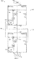
- FIG. 1 an exemplary modular solid state switch 120 for use in a power distribution network is shown.
- a power transmission line 110 extending from a power source 102 to a load 104, is connected to the switch 120.
- the switch 120 is a modular solid state switch.
- the switch 120 includes an input differential protection (DP) connection 126 at a first end 122 and an output DP connection 128 at a second, opposing end 124 of the solid state switch 120.
- the input DP connection 126 receives a current (scaled or un-scaled) value from an external source such as, for example, an upstream switch module as described below with reference to FIG. 2 .
- the output DP connection 128 provides an output current value (scaled or unsealed).
- the solid state switch 120 includes a current sensor 121 that measures the current of the power transmission line 110 as it passes through the solid state switch 120.
- Exemplary current sensors include differential voltage shunts, miniaturized Hall Effect sensors and giant magneto responsive (GMR) type sensors.
- the measured current is provided to both the output DP connection 128 and the input DP connection 126 for various purposes described herein.
- the measured current is provided to a summer 125 before being provided to the output DP connection 128 as is explained further below.
- the solid state switch 120 includes a comparator 123 connected to the input DP connection 126 and the current sensor 121.
- the comparator 123 evaluates the difference between the current measured by current sensor 121 and a measured current value of an upstream module received by input DP connection 126.
- the summer 125 includes the functionality of the comparator 123, and a separate comparator is unnecessary.
- Each modular solid state switch 120 additionally includes a trip outlet 130 from which a trip signal may be sent to at least one upstream module, and a trip inlet 132 in which a trip signal may be received from a downstream module.
- the trip outlet 130 is activated, in one example, which is not part of the invention, when the difference between the current measured by current sensor 121 and the current received at the input DP connection 126 exceeds a particular threshold level. In another example, which is not part of the invention, the difference is based on the sum produced in the summer 125 and the current received at the input DP connection 126. The level may be predefined and adjusted depending on the context.
- the trip outlet 130 is located adjacent the input DP connection 126.
- the trip outlet 130 is coupled to the comparator 123.
- the trip input 132 of the solid state switch 120 is operably coupled to a switch 134 for opening and closing the switch 134 to affect the flow of power along the power transmission line 110.
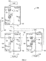
- FIG. 2 illustrates an exemplary portion of a power distribution network 100, such as in an aircraft, for example.
- a power transmission line 110 extending from a power source 102 to a load 104, is connected to multiple solid state switch modules 120, 140 in series.
- the first solid state switch module 120 is positioned upstream from a second solid state switch module 140 along the power transmission line 110.
- the second solid state switch module 140 Similar to the first solid state switch module 120, the second solid state switch module 140 includes a second input DP connection 146 adjacent a first end 142, a second output DP connection 148 proximal to a second end 144, a second trip outlet 150, and a second trip inlet 152 coupled to a second switch 154.
- the second solid state switch module 140 additionally includes a current sensor 141 for measuring the current of the power transmission line 110 through the second module 140, a comparator 143 for comparing input and output values at respective DP connections 146, 148 against a measured current value of an upstream module, and a summer 145 for adding the current measured by the current sensor 141 to a current measured in another (parallel) module.
- the first and second solid state switches 120 and 140 are identical, and therefore, are interchangeable within the power distribution network 100.
- the first output DP connection 128 is connected to the second input DP connection 146 by connection circuitry 160.
- the circuitry 160 additionally couples the second trip outlet 150 to the first trip inlet 132.
- the second input DP connection 146 receives a current value from the first output DP connection 128 of the first solid state switch 120.
- the current value is the current measured by current sensor 121.
- the current value could be the sum of the current measured by current sensor 121 and other current sensors (not shown).
- the comparator 143 within the second solid state switch module 140 compares the current measured by current sensor 141 with the measured current value received by the second input DP connection 146.
- Such a measurement can be used to determine the loss in current along the power transmission line 110 between the second solid state switch 140 and the first solid state switch 120. That is, the comparison can be used to determine if a fault exists in the transmission line 110 between the first 120 and second 140 switches. If the difference is greater than a selected or calculated allowable limit or threshold, the comparator 143, coupled to the second trip outlet 150, places a trip signal on the second trip outlet 150. The trip signal is conveyed to the first trip inlet 132, via the circuitry 160 coupling the first and second solid state switches 120, 140, causing the first switch 134 of the upstream first solid state switch 120 to open.
- the allowable threshold of the loss in current between adjacent tiers of solid state switches will vary with each application. In one example, which is not part of the invention, the allowable threshold is a difference in current of less than or equal to 8 percent.
- the first solid state switch module 120 and a third solid state switch module 180 are parallel source switches coupled to the second modular solid state switch 140, which acts as a single destination switch.
- the plurality of solid state switches within the network are identical and, therefore, the illustrated solid state switches 120, 140, 180 are interchangeable within the network 200.
- the first solid state switch 120 is connected to a first branch 110a of power transmission line 110
- the third solid state switch 180 is connected to a second branch 110b of power transmission line 110.
- the first branch 110a and the second branch 110b unite to form a single power transmission line 110.
- the power transmission provided in this example could be used for either alternating or direct current systems. In the event that the power is AC power, it is assumed that supplies 104 and 106 are in phase.
- the third solid state switch 180 has a third input DP connection 186 near a first end 182 and a third output DP connection 188 near a second, opposite end 184 of the third switch 180.
- the third solid state switch 180 additionally includes a current sensor 181, a comparator 183, and a summer 185 arranged in a manner similar to the first and second solid state switches 120, 140.
- the output DP connection 188 of the third solid state switch 180 is connected to a parallel input 136 of the first solid state switch 120 by wiring 196.
- the first and third solid state switches 120, 180 are parallel sources jointly providing power to the second solid state switch 140. Though only two solid state switches are illustrated, any number of parallel source switches or parallel destination switches (see FIG. 4 ) may be utilized without departing from the scope of the invention.
- the current measured by current sensor 141 should equal the sum of the current through the first solid state switch 120 and the current through the third solid state switch 180.
- the current in the third solid state switch 180, sensed by current sensor 181 is provided to summer 185. If an additional parallel source were coupled to the third solid state switch 180, the current measured in the module would also be input to summer 185.
- the signal provided to the output DP connection 188 by the summer 185 represents only the current measured by current sensor 181.
- the output DP connection 188 sends the "summed current measurement" from the third solid state switch to the parallel input 136 of the first module 120.
- the summer 125 of the first solid state switch 120 adds the measured current value received by the parallel input 136 with the current measured in the first module 120 by current sensor 121.
- a signal representing the value of this summation is then sent from output DP connection 128 to the input DP connection 146 of the second module 140 for comparison.
- the functionality of the summer and comparator are integrated into a single device.
- the comparator 143 will cause second trip out 150 to send a trip signal to open the switches of both the first solid state switch 120 and the third solid state switch 180.
- FIG. 4 An exemplary portion of an alternate power distribution network 300 is illustrated in FIG. 4 .
- the first solid state switch module 120 and a third solid state switch module 180 are parallel source switches coupled to a plurality of parallel downstream solid state switches 140, 430, 450, 470 and each received power from respective power supply busses 500, 501.
- Each of the illustrated downstream solid state switches 140, 430, 450, 470 is connected to a load L1-L4 respectively.
- the plurality of solid state switches within the network are identical and therefore, the illustrated solid state switches 120, 180, 140, 430, 450, 470 are interchangeable within the network 300. Similar to the system illustrated in FIG.
- the first solid state switch 120 is connected to a first branch 110a of power transmission line 110
- the third solid state switch 180 is connected to a second branch 110b of power transmission line 110.
- the output DP connection 188 of the third solid state switch 180 is connected to a parallel input 136 of the first solid state switch 120 by wiring 196.
- each of the parallel downstream solid state switches is connected to an input of an adjacent switch by wiring 402, 404, 406 respectively.
- the current measured by current sensor 181 in the third solid state switch 180 is summed by summer 185 with the current of an adjacent solid state switch.
- the "summed current measurement" from the third solid state switch 180 is sent to an input 136 of the first solid state switch 120.
- the summer 125 of the first solid state switch 120 adds the measured current value received by the parallel input 136 with the current measured by current sensor 121.
- a current sensor 471 measures the current in a solid state switch 470.
- the measured current value is then provided as an input to the adjacent solid state switch 450.
- a summer 455 adds the measured current value of the adjacent solid state switch 470 with the current measured by current sensor 451.
- the total current value of solid state switches 450 and 470 is transmitted to solid state switch 430 by wiring 404.
- the current sensor 431 measures the current in the upstream solid state switch 430.
- the current measured by current sensor 431 is then added to the measured current value of solid state switches 450 and 470 by summer 435 and is provided as an input to the downstream solid state switch 140 across wiring 402.
- a summation is then taken of the current measured by current sensor 141 and the current of the solid state switches 430, 450 and 470 to get a total downstream current value. Because the downstream solid state switches are connected in parallel, the current values of each solid state switch are summed at the solid state switch connected to an output DP connection of an upstream solid state switch. Therefore, comparators 433, 453, and 473 do not perform any comparison in the illustrated example.
- the summation of the upstream current in the upstream solid state switches is sent from output DP connection 128 to the input DP connection 146 of the second solid state switch 140 for comparison. If the difference between the downstream current and the total upstream current is not within an allowable threshold, the comparator 143 will cause trip out 150 to send a trip signal over circuitry 166 to open the switches of all of the upstream switches.
Landscapes
- Engineering & Computer Science (AREA)
- Power Engineering (AREA)
- Remote Monitoring And Control Of Power-Distribution Networks (AREA)
Claims (11)
- Leistungsverteilungsnetz, umfassend:eine Leistungsübertragungsleitung;ein erstes Festkörperschaltermodul (120), das dazu konfiguriert ist, Differentialschutz bereitzustellen, wobei das erste Festkörperschaltermodul (120) an einer ersten Stelle elektrisch an die Leistungsübertragungsleitung (110) gekoppelt ist, wobei das erste Festkörperschaltermodul (120) dazu konfiguriert ist, einen ersten Stromwert in der Leistungsübertragungsleitung (110) an der ersten Stelle zu bestimmen;ein zweites Festkörperschaltermodul (140), das dazu konfiguriert ist, Differentialschutz (140) bereitzustellen, das an einer zweiten Stelle mit der Leistungsübertragungsleitung (110) verbunden ist, wobei das zweite Festkörperschaltermodul (140) identisch mit dem ersten Festkörperschaltermodul (120) ist und allgemein dem ersten Festkörperschaltermodul nachgeordnet angeordnet ist, wobei das zweite Festkörperschaltermodul (140) dazu konfiguriert ist, einen zweiten Stromwert in der Leistungsübertragungsleitung an der zweiten Stelle zu bestimmen; Schalttechnik, die das zweite Festkörperschaltermodul (140) und das erste Festkörperschaltermodul (120) koppelt, um einen Stromwert zu dem zweiten Festkörperschaltermodul zu übermitteln; undein drittes Festkörperschaltermodul (180), das identisch mit dem ersten Festkörperschaltermodul (120) und dem zweiten Festkörperschaltermodul (140) ist, das elektrisch an einer dritten Stelle an die Leistungsübertragungsleitung (110) gekoppelt und derart angeordnet ist, dass das erste Festkörperschaltermodul (120) und das dritte Festkörperschaltermodul (180) als parallele Quellen zusammen dem zweiten Festkörperschaltermodul (140) elektrische Leistung bereitstellen, wobei das dritte Festkörperschaltermodul (180) dazu konfiguriert ist, einen dritten Stromwert in der Leistungsübertragungsleitung (110) an der dritten Stelle zu bestimmen,wobei das erste Festkörperschaltermodul (120) dazu konfiguriert ist, den ersten Strom und den dritten Strom zu summieren und die Summe durch die koppelnde Schalttechnik zu dem zweiten Festkörperschaltermodul (140) zu übermitteln; undwobei das zweite Festkörperschaltermodul (140) dazu konfiguriert ist, den zweiten Strom mit der Summe des ersten Stroms und des dritten Stroms zu vergleichen, um eine Differenz zu bestimmen, wobei das zweite Festkörperschaltermodul (140) dazu konfiguriert ist, als Reaktion darauf, dass die Differenz größer ist als ein ausgewählter Schwellenwert, ein Auslösesignal an das erste Festkörperschaltermodul und an das dritte Festkörperschaltermodul (180) zu übertragen, wobei das Auslösesignal bewirkt, dass sich sowohl das erste Festkörperschaltermodul (120) als auch das dritte Festkörperschaltermodul (180) öffnet und eine Übertragung von Elektrizität durch diese unterbricht.
- Leistungsverteilungsnetz nach Anspruch 1, wobei das erste Festkörperschaltermodul (120), das zweite Festkörperschaltermodul (140) und das dritte Festkörperschaltermodul (180) innerhalb des Leistungsverteilungsnetzes (110) austauschbar sind.
- Leistungsverteilungsnetz nach Anspruch 1, ferner umfassend: mindestens ein zusätzliches Festkörperschaltermodul, das dazu konfiguriert ist, Differentialschutz bereitzustellen, wobei das mindestens eine zusätzliche Festkörperschaltermodul identisch mit dem ersten, dritten und zweiten Festkörperschaltermodul ist und in Bezug auf die Leistungsübertragungsleitung (110) parallel mit entweder dem ersten Festkörperschaltermodul (120) oder dem zweiten Festkörperschaltermodul (140) verbunden ist.
- Leistungsverteilungsnetz nach einem der Ansprüche 1 bis 3, wobei der ausgewählte Schwellenwert allgemein geringer als eine Differenz von 8 % oder gleich dieser ist.
- Verfahren zum Identifizieren eines Leistungsverlustes innerhalb eines Leistungsverteilungsnetzes, umfassend:Messen eines Stroms einer Leistungsübertragungsleitung (110) an einer ersten Stelle an einem ersten Festkörperschaltermodul (120), das dazu konfiguriert ist, Differentialschutz bereitzustellen;Messen des Stroms der Leistungsübertragungsleitung an einer zweiten Stelle an einem zweiten Festkörperschaltermodul (140), das dazu konfiguriert ist, Differentialschutz bereitzustellen, wobei das zweite Festkörperschaltermodul (140) identisch mit dem ersten Festkörperschaltermodul (120) ist und an einer nachgelagerten Stelle an der Leistungsübertragungsleitung in Bezug auf das erste Festkörperschaltermodul angeordnet ist;Messen des Stroms der Leistungsübertragungsleitung an einer dritten Stelle an einem dritten Festkörperschaltermodul (180), das elektrisch an der dritten Stelle an die Leistungsübertragungsleitung gekoppelt ist, wobei das dritte Festkörperschaltermodul derart angeordnet ist, dass das erste Festkörperschaltermodul (120) und das dritte Festkörperschaltermodul (180) als parallele Quellen zusammen dem zweiten Festkörperschaltermodul (140) elektrische Leistung bereitstellen, wobei das dritte Festkörperschaltermodul identisch mit dem ersten (120) und dem zweiten (140) Festkörperschaltermodul ist;an dem ersten Festkörperschaltermodul, Addieren des Stromwerts, der durch das erste Festkörperschaltermodul gemessen wird, und des Stromwerts, der durch das dritte Festkörperschaltermodul gemessen wird, und Übermitteln der Summe an das zweite Festkörperschaltermodul;an dem zweiten Festkörperschaltermodul (140), Vergleichen des gemessenen Stroms des zweiten Festkörperschaltermoduls mit der Summe des gemessenen Stroms des ersten Festkörperschaltermoduls (120) und des gemessenen Stroms an dem dritten Festkörperschaltermodul, um eine Differenz zu bestimmen;Bewerten, ob die Differenz über einem ausgewählten Schwellenwert liegt; undSenden eines Auslösesignals von dem zweiten Festkörperschaltermodul an das erste Festkörperschaltermodul und an das dritte Festkörperschaltermodul (180), wenn die Differenz über dem ausgewählten Schwellenwert liegt, wobei das Auslösesignal bewirkt, dass sich sowohl das vorgelagerte als auch das dritte Festkörperschaltermodul öffnet und die Übertragung von Elektrizität durch diese unterbricht.
- Verfahren nach Anspruch 5, wobei das zweite Festkörperschaltermodul (140) einen Stromsensor (141) beinhaltet und/oder wobei ein Komparator (143) in dem zweiten Festkörperschaltermodul den gemessenen Strom des zweiten Festkörperschaltermoduls mit der Summe des gemessenen Stroms des ersten Festkörperschaltermoduls (120) und des gemessenen Stroms an dem dritten Festkörperschaltermodul (180) vergleicht.
- Verfahren nach Ansprüchen 5 oder 6, wobei das erste Festkörperschaltermodul (120), das dritte Festkörperschaltermodul (180) und das zweite Festkörperschaltermodul (140) innerhalb des Leistungsverteilungsnetzes austauschbar sind.
- Leistungsverteilungsnetz nach Anspruch 1, wobei jedes von dem ersten Festkörperschaltermodul (120), dem dritten Festkörperschaltermodul (180) und dem zweiten Festkörpermodul (140) einen Komparator beinhaltet, wobei der Komparator des ersten Festkörperschaltermoduls (120) dazu konfiguriert ist, eine Differenz zwischen dem zweiten Stromwert und der Summe des dritten und des ersten Stromwerts zu berechnen.
- Leistungsverteilungsnetz nach Anspruch 1, wobei jedes von dem ersten Festkörperschaltermodul (120), dem dritten Festkörperschaltermodul (180) und dem zweiten Festkörpermodul (140) einen Stromsensor beinhaltet, der dazu konfiguriert ist, einen Strom der Leistungsübertragungsleitung an einer Stelle zu messen.
- Leistungsverteilungsnetz nach Anspruch 1 oder 8, wobei jedes von dem ersten Festkörperschaltermodul (120), dem dritten Festkörperschaltermodul (180) und dem zweiten Festkörpermodul (140) einen Summierer beinhaltet, der dazu konfiguriert ist, einen Stromeingang von einem Festkörperschaltermodul, das in Bezug auf die Leistungsübertragungsleitung (110) parallel mit dem zweiten Festkörpermodul verbunden ist, zu einem Strom, der durch den Stromsensor gemessen wird, zu addieren.
- Leistungsverteilungsnetz nach Anspruch 1 oder 8, wobei jedes von dem ersten Festkörperschaltermodul (120), dem dritten Festkörperschaltermodul (180) und dem zweiten Festkörpermodul (140) ferner Folgendes beinhaltet:eine Eingangs-Differentialschutzverbindung, die dazu konfiguriert ist, einen gemessenen Stromwert zu empfangen;eine Ausgangs-Differentialschutzverbindung, die dazu konfiguriert ist, einen durch den Stromsensor gemessenen Stromwert zu senden;einen Auslöseauslass, der dazu konfiguriert ist, ein Auslösesignal zu senden; undeinen Auslöseeinlass, der dazu konfiguriert ist, ein Auslösesignal zu empfangen.
Applications Claiming Priority (1)
| Application Number | Priority Date | Filing Date | Title |
|---|---|---|---|
| US13/456,898 US9362736B2 (en) | 2012-04-26 | 2012-04-26 | Method for improving power distribution protection |
Publications (2)
| Publication Number | Publication Date |
|---|---|
| EP2658065A1 EP2658065A1 (de) | 2013-10-30 |
| EP2658065B1 true EP2658065B1 (de) | 2022-04-20 |
Family
ID=48226985
Family Applications (1)
| Application Number | Title | Priority Date | Filing Date |
|---|---|---|---|
| EP13165366.9A Active EP2658065B1 (de) | 2012-04-26 | 2013-04-25 | Verfahren zur Verbesserung des Leistungsverteilungsschutzes |
Country Status (2)
| Country | Link |
|---|---|
| US (1) | US9362736B2 (de) |
| EP (1) | EP2658065B1 (de) |
Families Citing this family (5)
| Publication number | Priority date | Publication date | Assignee | Title |
|---|---|---|---|---|
| WO2012096212A1 (ja) * | 2011-01-11 | 2012-07-19 | アルプス・グリーンデバイス株式会社 | 電流センサ |
| US10642229B2 (en) * | 2014-07-22 | 2020-05-05 | Hamilton Sundstrand Corporation | Coordination of variable groupings of control channels |
| CN105449646B (zh) * | 2014-08-14 | 2018-10-23 | 国家电网公司 | 一种配电网电磁环网阻抗解析方法 |
| US10938314B2 (en) | 2018-07-23 | 2021-03-02 | Smart Wires Inc. | Early detection of faults in power transmission lines |
| CN118921048B (zh) * | 2024-10-11 | 2025-03-18 | 山东航天电子技术研究所 | 一种基于巨磁电阻效应的卫星固态配电开关 |
Citations (1)
| Publication number | Priority date | Publication date | Assignee | Title |
|---|---|---|---|---|
| FR1421236A (fr) * | 1962-10-20 | 1965-12-17 | Merlin Gerin | Système de protection sélective pour réseaux électriques |
Family Cites Families (2)
| Publication number | Priority date | Publication date | Assignee | Title |
|---|---|---|---|---|
| CH554096A (fr) | 1970-12-17 | 1974-09-13 | Merlin Gerin | Dispositif de protection selective d'un reseau de distribution d'energie electrique. |
| US4631622A (en) * | 1984-12-31 | 1986-12-23 | General Electric Company | Multiple static trip circuit breaker coordination |
-
2012
- 2012-04-26 US US13/456,898 patent/US9362736B2/en active Active
-
2013
- 2013-04-25 EP EP13165366.9A patent/EP2658065B1/de active Active
Patent Citations (1)
| Publication number | Priority date | Publication date | Assignee | Title |
|---|---|---|---|---|
| FR1421236A (fr) * | 1962-10-20 | 1965-12-17 | Merlin Gerin | Système de protection sélective pour réseaux électriques |
Also Published As
| Publication number | Publication date |
|---|---|
| US9362736B2 (en) | 2016-06-07 |
| US20130286524A1 (en) | 2013-10-31 |
| EP2658065A1 (de) | 2013-10-30 |
Similar Documents
| Publication | Publication Date | Title |
|---|---|---|
| CN105474660B (zh) | 具有多个电池组电池的电池组的电池组管理系统和方法 | |
| EP2658065B1 (de) | Verfahren zur Verbesserung des Leistungsverteilungsschutzes | |
| US10569895B2 (en) | Systems, methods, and devices for bipolar high voltage direct current ground fault detection | |
| US7626791B2 (en) | Electrical fault detection | |
| EP2360805B1 (de) | Elektrisches Energieübertragungssystem eines Fahrzeugs | |
| Tang et al. | A wide area differential backup protection scheme for shipboard application | |
| MX2014010385A (es) | Hacer uso de redundancia inherente en un dispositivo electronico inteligente multifuncional. | |
| CN110015081A (zh) | 对电动车辆的电能存储构件充电的具有差动电流监测的充电站 | |
| CN102221819A (zh) | 用于现场设备的连接装置和用于运行的方法 | |
| CN109228873A (zh) | 列车和列车供电系统及其漏电检测恢复装置、方法 | |
| US20180186248A1 (en) | Connection module for an electrical energy storage device, and power supply system | |
| US9755418B2 (en) | Fuse protection for a line | |
| EP2654154A2 (de) | Leistungsverwaltung und -verteilungssystem mit Fehlererkennung und Isolierungsanordnung und Verfahren | |
| EP2645114A2 (de) | Anordnung zur derzeitigen Messung und Vergleich für ein Leistungsverteilungssystem und Verfahren zum Messen und Vergleichen von Strom | |
| EP3882643B1 (de) | Detektion von lichtbogenzonenfehler | |
| CN108780989B (zh) | 电力系统中或关于电力系统的改进 | |
| US12210047B2 (en) | DC electrical network | |
| US9281677B2 (en) | Method for protecting an electrical energy distribution box | |
| US8755159B2 (en) | System of current protection of a primary electrical distribution box | |
| US9331470B1 (en) | Line side circuit protection system | |
| RU2611059C2 (ru) | Способ измерения для обнаружения повреждения трехфазной сети | |
| US20130313901A1 (en) | Electrical power supply system having internal fault protection | |
| KR101307939B1 (ko) | 변류기 보호기능을 갖는 수배전반 | |
| US8988837B2 (en) | Power distribution system incorporating ground fault interrupt protection |
Legal Events
| Date | Code | Title | Description |
|---|---|---|---|
| PUAI | Public reference made under article 153(3) epc to a published international application that has entered the european phase |
Free format text: ORIGINAL CODE: 0009012 |
|
| AK | Designated contracting states |
Kind code of ref document: A1 Designated state(s): AL AT BE BG CH CY CZ DE DK EE ES FI FR GB GR HR HU IE IS IT LI LT LU LV MC MK MT NL NO PL PT RO RS SE SI SK SM TR |
|
| AX | Request for extension of the european patent |
Extension state: BA ME |
|
| 17P | Request for examination filed |
Effective date: 20140430 |
|
| RBV | Designated contracting states (corrected) |
Designated state(s): AL AT BE BG CH CY CZ DE DK EE ES FI FR GB GR HR HU IE IS IT LI LT LU LV MC MK MT NL NO PL PT RO RS SE SI SK SM TR |
|
| STAA | Information on the status of an ep patent application or granted ep patent |
Free format text: STATUS: EXAMINATION IS IN PROGRESS |
|
| 17Q | First examination report despatched |
Effective date: 20161031 |
|
| GRAP | Despatch of communication of intention to grant a patent |
Free format text: ORIGINAL CODE: EPIDOSNIGR1 |
|
| STAA | Information on the status of an ep patent application or granted ep patent |
Free format text: STATUS: GRANT OF PATENT IS INTENDED |
|
| RIC1 | Information provided on ipc code assigned before grant |
Ipc: H02H 3/30 20060101ALN20211021BHEP Ipc: H02H 7/26 20060101ALN20211021BHEP Ipc: H02H 7/30 20060101AFI20211021BHEP |
|
| INTG | Intention to grant announced |
Effective date: 20211108 |
|
| RAP3 | Party data changed (applicant data changed or rights of an application transferred) |
Owner name: HAMILTON SUNDSTRAND CORPORATION |
|
| GRAS | Grant fee paid |
Free format text: ORIGINAL CODE: EPIDOSNIGR3 |
|
| GRAA | (expected) grant |
Free format text: ORIGINAL CODE: 0009210 |
|
| STAA | Information on the status of an ep patent application or granted ep patent |
Free format text: STATUS: THE PATENT HAS BEEN GRANTED |
|
| AK | Designated contracting states |
Kind code of ref document: B1 Designated state(s): AL AT BE BG CH CY CZ DE DK EE ES FI FR GB GR HR HU IE IS IT LI LT LU LV MC MK MT NL NO PL PT RO RS SE SI SK SM TR |
|
| REG | Reference to a national code |
Ref country code: GB Ref legal event code: FG4D |
|
| REG | Reference to a national code |
Ref country code: CH Ref legal event code: EP |
|
| REG | Reference to a national code |
Ref country code: IE Ref legal event code: FG4D |
|
| REG | Reference to a national code |
Ref country code: DE Ref legal event code: R096 Ref document number: 602013081444 Country of ref document: DE |
|
| REG | Reference to a national code |
Ref country code: AT Ref legal event code: REF Ref document number: 1485955 Country of ref document: AT Kind code of ref document: T Effective date: 20220515 |
|
| REG | Reference to a national code |
Ref country code: LT Ref legal event code: MG9D |
|
| REG | Reference to a national code |
Ref country code: NL Ref legal event code: MP Effective date: 20220420 |
|
| REG | Reference to a national code |
Ref country code: AT Ref legal event code: MK05 Ref document number: 1485955 Country of ref document: AT Kind code of ref document: T Effective date: 20220420 |
|
| PG25 | Lapsed in a contracting state [announced via postgrant information from national office to epo] |
Ref country code: NL Free format text: LAPSE BECAUSE OF FAILURE TO SUBMIT A TRANSLATION OF THE DESCRIPTION OR TO PAY THE FEE WITHIN THE PRESCRIBED TIME-LIMIT Effective date: 20220420 |
|
| PG25 | Lapsed in a contracting state [announced via postgrant information from national office to epo] |
Ref country code: SE Free format text: LAPSE BECAUSE OF FAILURE TO SUBMIT A TRANSLATION OF THE DESCRIPTION OR TO PAY THE FEE WITHIN THE PRESCRIBED TIME-LIMIT Effective date: 20220420 Ref country code: PT Free format text: LAPSE BECAUSE OF FAILURE TO SUBMIT A TRANSLATION OF THE DESCRIPTION OR TO PAY THE FEE WITHIN THE PRESCRIBED TIME-LIMIT Effective date: 20220822 Ref country code: NO Free format text: LAPSE BECAUSE OF FAILURE TO SUBMIT A TRANSLATION OF THE DESCRIPTION OR TO PAY THE FEE WITHIN THE PRESCRIBED TIME-LIMIT Effective date: 20220720 Ref country code: LT Free format text: LAPSE BECAUSE OF FAILURE TO SUBMIT A TRANSLATION OF THE DESCRIPTION OR TO PAY THE FEE WITHIN THE PRESCRIBED TIME-LIMIT Effective date: 20220420 Ref country code: HR Free format text: LAPSE BECAUSE OF FAILURE TO SUBMIT A TRANSLATION OF THE DESCRIPTION OR TO PAY THE FEE WITHIN THE PRESCRIBED TIME-LIMIT Effective date: 20220420 Ref country code: GR Free format text: LAPSE BECAUSE OF FAILURE TO SUBMIT A TRANSLATION OF THE DESCRIPTION OR TO PAY THE FEE WITHIN THE PRESCRIBED TIME-LIMIT Effective date: 20220721 Ref country code: FI Free format text: LAPSE BECAUSE OF FAILURE TO SUBMIT A TRANSLATION OF THE DESCRIPTION OR TO PAY THE FEE WITHIN THE PRESCRIBED TIME-LIMIT Effective date: 20220420 Ref country code: ES Free format text: LAPSE BECAUSE OF FAILURE TO SUBMIT A TRANSLATION OF THE DESCRIPTION OR TO PAY THE FEE WITHIN THE PRESCRIBED TIME-LIMIT Effective date: 20220420 Ref country code: BG Free format text: LAPSE BECAUSE OF FAILURE TO SUBMIT A TRANSLATION OF THE DESCRIPTION OR TO PAY THE FEE WITHIN THE PRESCRIBED TIME-LIMIT Effective date: 20220720 Ref country code: AT Free format text: LAPSE BECAUSE OF FAILURE TO SUBMIT A TRANSLATION OF THE DESCRIPTION OR TO PAY THE FEE WITHIN THE PRESCRIBED TIME-LIMIT Effective date: 20220420 |
|
| REG | Reference to a national code |
Ref country code: DE Ref legal event code: R119 Ref document number: 602013081444 Country of ref document: DE |
|
| PG25 | Lapsed in a contracting state [announced via postgrant information from national office to epo] |
Ref country code: RS Free format text: LAPSE BECAUSE OF FAILURE TO SUBMIT A TRANSLATION OF THE DESCRIPTION OR TO PAY THE FEE WITHIN THE PRESCRIBED TIME-LIMIT Effective date: 20220420 Ref country code: PL Free format text: LAPSE BECAUSE OF FAILURE TO SUBMIT A TRANSLATION OF THE DESCRIPTION OR TO PAY THE FEE WITHIN THE PRESCRIBED TIME-LIMIT Effective date: 20220420 Ref country code: LV Free format text: LAPSE BECAUSE OF FAILURE TO SUBMIT A TRANSLATION OF THE DESCRIPTION OR TO PAY THE FEE WITHIN THE PRESCRIBED TIME-LIMIT Effective date: 20220420 Ref country code: IS Free format text: LAPSE BECAUSE OF FAILURE TO SUBMIT A TRANSLATION OF THE DESCRIPTION OR TO PAY THE FEE WITHIN THE PRESCRIBED TIME-LIMIT Effective date: 20220820 |
|
| REG | Reference to a national code |
Ref country code: CH Ref legal event code: PL |
|
| REG | Reference to a national code |
Ref country code: BE Ref legal event code: MM Effective date: 20220430 |
|
| PG25 | Lapsed in a contracting state [announced via postgrant information from national office to epo] |
Ref country code: SM Free format text: LAPSE BECAUSE OF FAILURE TO SUBMIT A TRANSLATION OF THE DESCRIPTION OR TO PAY THE FEE WITHIN THE PRESCRIBED TIME-LIMIT Effective date: 20220420 Ref country code: SK Free format text: LAPSE BECAUSE OF FAILURE TO SUBMIT A TRANSLATION OF THE DESCRIPTION OR TO PAY THE FEE WITHIN THE PRESCRIBED TIME-LIMIT Effective date: 20220420 Ref country code: RO Free format text: LAPSE BECAUSE OF FAILURE TO SUBMIT A TRANSLATION OF THE DESCRIPTION OR TO PAY THE FEE WITHIN THE PRESCRIBED TIME-LIMIT Effective date: 20220420 Ref country code: MC Free format text: LAPSE BECAUSE OF FAILURE TO SUBMIT A TRANSLATION OF THE DESCRIPTION OR TO PAY THE FEE WITHIN THE PRESCRIBED TIME-LIMIT Effective date: 20220420 Ref country code: LU Free format text: LAPSE BECAUSE OF NON-PAYMENT OF DUE FEES Effective date: 20220425 Ref country code: LI Free format text: LAPSE BECAUSE OF NON-PAYMENT OF DUE FEES Effective date: 20220430 Ref country code: EE Free format text: LAPSE BECAUSE OF FAILURE TO SUBMIT A TRANSLATION OF THE DESCRIPTION OR TO PAY THE FEE WITHIN THE PRESCRIBED TIME-LIMIT Effective date: 20220420 Ref country code: DK Free format text: LAPSE BECAUSE OF FAILURE TO SUBMIT A TRANSLATION OF THE DESCRIPTION OR TO PAY THE FEE WITHIN THE PRESCRIBED TIME-LIMIT Effective date: 20220420 Ref country code: DE Free format text: LAPSE BECAUSE OF NON-PAYMENT OF DUE FEES Effective date: 20221103 Ref country code: CZ Free format text: LAPSE BECAUSE OF FAILURE TO SUBMIT A TRANSLATION OF THE DESCRIPTION OR TO PAY THE FEE WITHIN THE PRESCRIBED TIME-LIMIT Effective date: 20220420 Ref country code: CH Free format text: LAPSE BECAUSE OF NON-PAYMENT OF DUE FEES Effective date: 20220430 |
|
| PLBE | No opposition filed within time limit |
Free format text: ORIGINAL CODE: 0009261 |
|
| STAA | Information on the status of an ep patent application or granted ep patent |
Free format text: STATUS: NO OPPOSITION FILED WITHIN TIME LIMIT |
|
| PG25 | Lapsed in a contracting state [announced via postgrant information from national office to epo] |
Ref country code: BE Free format text: LAPSE BECAUSE OF NON-PAYMENT OF DUE FEES Effective date: 20220430 |
|
| 26N | No opposition filed |
Effective date: 20230123 |
|
| PG25 | Lapsed in a contracting state [announced via postgrant information from national office to epo] |
Ref country code: AL Free format text: LAPSE BECAUSE OF FAILURE TO SUBMIT A TRANSLATION OF THE DESCRIPTION OR TO PAY THE FEE WITHIN THE PRESCRIBED TIME-LIMIT Effective date: 20220420 |
|
| PG25 | Lapsed in a contracting state [announced via postgrant information from national office to epo] |
Ref country code: IE Free format text: LAPSE BECAUSE OF NON-PAYMENT OF DUE FEES Effective date: 20220425 |
|
| PG25 | Lapsed in a contracting state [announced via postgrant information from national office to epo] |
Ref country code: SI Free format text: LAPSE BECAUSE OF FAILURE TO SUBMIT A TRANSLATION OF THE DESCRIPTION OR TO PAY THE FEE WITHIN THE PRESCRIBED TIME-LIMIT Effective date: 20220420 |
|
| P01 | Opt-out of the competence of the unified patent court (upc) registered |
Effective date: 20230522 |
|
| PG25 | Lapsed in a contracting state [announced via postgrant information from national office to epo] |
Ref country code: IT Free format text: LAPSE BECAUSE OF FAILURE TO SUBMIT A TRANSLATION OF THE DESCRIPTION OR TO PAY THE FEE WITHIN THE PRESCRIBED TIME-LIMIT Effective date: 20220420 |
|
| PG25 | Lapsed in a contracting state [announced via postgrant information from national office to epo] |
Ref country code: HU Free format text: LAPSE BECAUSE OF FAILURE TO SUBMIT A TRANSLATION OF THE DESCRIPTION OR TO PAY THE FEE WITHIN THE PRESCRIBED TIME-LIMIT; INVALID AB INITIO Effective date: 20130425 |
|
| PG25 | Lapsed in a contracting state [announced via postgrant information from national office to epo] |
Ref country code: MK Free format text: LAPSE BECAUSE OF FAILURE TO SUBMIT A TRANSLATION OF THE DESCRIPTION OR TO PAY THE FEE WITHIN THE PRESCRIBED TIME-LIMIT Effective date: 20220420 Ref country code: CY Free format text: LAPSE BECAUSE OF FAILURE TO SUBMIT A TRANSLATION OF THE DESCRIPTION OR TO PAY THE FEE WITHIN THE PRESCRIBED TIME-LIMIT Effective date: 20220420 |
|
| PG25 | Lapsed in a contracting state [announced via postgrant information from national office to epo] |
Ref country code: MT Free format text: LAPSE BECAUSE OF FAILURE TO SUBMIT A TRANSLATION OF THE DESCRIPTION OR TO PAY THE FEE WITHIN THE PRESCRIBED TIME-LIMIT Effective date: 20220420 |
|
| PG25 | Lapsed in a contracting state [announced via postgrant information from national office to epo] |
Ref country code: BG Free format text: LAPSE BECAUSE OF FAILURE TO SUBMIT A TRANSLATION OF THE DESCRIPTION OR TO PAY THE FEE WITHIN THE PRESCRIBED TIME-LIMIT Effective date: 20220420 |
|
| PG25 | Lapsed in a contracting state [announced via postgrant information from national office to epo] |
Ref country code: BG Free format text: LAPSE BECAUSE OF FAILURE TO SUBMIT A TRANSLATION OF THE DESCRIPTION OR TO PAY THE FEE WITHIN THE PRESCRIBED TIME-LIMIT Effective date: 20220420 |
|
| PG25 | Lapsed in a contracting state [announced via postgrant information from national office to epo] |
Ref country code: TR Free format text: LAPSE BECAUSE OF FAILURE TO SUBMIT A TRANSLATION OF THE DESCRIPTION OR TO PAY THE FEE WITHIN THE PRESCRIBED TIME-LIMIT Effective date: 20220420 |
|
| PGFP | Annual fee paid to national office [announced via postgrant information from national office to epo] |
Ref country code: GB Payment date: 20260319 Year of fee payment: 14 |
|
| PGFP | Annual fee paid to national office [announced via postgrant information from national office to epo] |
Ref country code: FR Payment date: 20260320 Year of fee payment: 14 |