EP2658068A1 - Dispositif de détection de surtension - Google Patents
Dispositif de détection de surtension Download PDFInfo
- Publication number
- EP2658068A1 EP2658068A1 EP13165459.2A EP13165459A EP2658068A1 EP 2658068 A1 EP2658068 A1 EP 2658068A1 EP 13165459 A EP13165459 A EP 13165459A EP 2658068 A1 EP2658068 A1 EP 2658068A1
- Authority
- EP
- European Patent Office
- Prior art keywords
- voltage
- conductor
- indicator
- live
- fuse
- Prior art date
- Legal status (The legal status is an assumption and is not a legal conclusion. Google has not performed a legal analysis and makes no representation as to the accuracy of the status listed.)
- Granted
Links
Images


Classifications
-
- H—ELECTRICITY
- H02—GENERATION; CONVERSION OR DISTRIBUTION OF ELECTRIC POWER
- H02H—EMERGENCY PROTECTIVE CIRCUIT ARRANGEMENTS
- H02H1/00—Details of emergency protective circuit arrangements
- H02H1/0038—Details of emergency protective circuit arrangements concerning the connection of the detecting means, e.g. for reducing their number
- H02H1/0053—Means for storing the measured quantities during a predetermined time
-
- H—ELECTRICITY
- H02—GENERATION; CONVERSION OR DISTRIBUTION OF ELECTRIC POWER
- H02H—EMERGENCY PROTECTIVE CIRCUIT ARRANGEMENTS
- H02H9/00—Emergency protective circuit arrangements for limiting excess current or voltage without disconnection
- H02H9/04—Emergency protective circuit arrangements for limiting excess current or voltage without disconnection responsive to excess voltage
- H02H9/042—Emergency protective circuit arrangements for limiting excess current or voltage without disconnection responsive to excess voltage comprising means to limit the absorbed power or indicate damaged over-voltage protection device
-
- H—ELECTRICITY
- H02—GENERATION; CONVERSION OR DISTRIBUTION OF ELECTRIC POWER
- H02H—EMERGENCY PROTECTIVE CIRCUIT ARRANGEMENTS
- H02H9/00—Emergency protective circuit arrangements for limiting excess current or voltage without disconnection
- H02H9/04—Emergency protective circuit arrangements for limiting excess current or voltage without disconnection responsive to excess voltage
- H02H9/06—Emergency protective circuit arrangements for limiting excess current or voltage without disconnection responsive to excess voltage using spark-gap arresters
Definitions
- the present invention relates to an apparatus and a method for detecting overvoltage.
- the device has at least one live conductor and at least one non-voltage-carrying conductor, wherein the at least one live conductor is connected to a first voltage indicator, which is configured to be permeable to voltage only after reaching a predetermined threshold voltage.
- the DE 38 34 868 A1 describes surge arresters that become conductive when an overvoltage occurs in a line, reducing the voltage applied and preventing damage to the equipment being protected.
- the US 5101180 describes a filter circuit for a communication line with protection against surge current with varistors that conduct a surge to ground and a fuse that the can interrupt direct line.
- the EP 0046545 A1 shows an overvoltage protection device with a fuse in each conductor and between each conductor and the ground, respectively, a surge arrester having a separator.
- the DE 10107357 C2 shows a signal display device for a surge arrester, which is inserted in a Ableitstrombahn.
- the DE 1513567 shows on a conductor in series connection a disconnecting fuse, a lightning protection element and an elastic connecting portion, which is connected to the ground and spaced when disconnecting the fuse the lightning arrester from the conductor.
- the WO 2007/093217 A1 shows a protection circuit for a data line having a fuse in the data line and connected in the secure data line section has a grounded conductor with a gas discharge tube and parallel to a grounded conductor with a reference gas discharge tube, in a subsequent section in two parallel conductor with Resistors and diodes passes, between which an alarm circuit is connected.
- the WO 00/31852 A1 shows a protection circuit against voltage pulses, which has a fuse between the input and output of each conductor of a telephone line and a connection of each conductor to the ground, in which a varistor or a gas arrester is included to derive voltage pulses, and a protective circuit terminating a connection cable and for the live conductor and grounding contains fuses, the neutral conductor and the live conductor being connected to the ground via a gas discharge tube; alternatively, the protective circuit terminating the connection cable can connect the live conductor and neutral to the ground via a gas discharge tube.
- the US 2002/0153989 A1 shows a surge arrester, in which a fuse is arranged in the live conductor and the neutral conductor and the voltage-carrying conductor via a respective varistor and a common fuse are connected to the ground.
- the EP 61652 A1 describes a parallel-connected arrester of a gas discharge path and a varistor which connects the line to the ground and an overvoltage protection circuit, in parallel between a voltage-carrying conductor and neutral conductor a varistor and a surge arrester are connected and an associated fuse is arranged in the conductor.
- the DE 2813115 A1 shows a circuit which is connectable to a polyphase network, which provides for each phase conductor, a control lamp whose output is connected to a neutral conductor and provides a fuse in each phase conductor and for each phase conductor and the neutral one
- the EP 678961 A1 shows a circuit for indicating the interruption of a line between two poles, in the lines fuses are arranged, wherein after a fuse and a varistor, a spark gap is arranged in a connecting line between a line and the ground.
- the AU-B-15147 shows a protection circuit in which a varistor and a fuse are arranged in series between two conductors.
- the US 2005/0180080 A1 describes a device for protection against overvoltage, in which a device arranged at the output of a line technical device is protected when an overvoltage occurs by an upstream isolation element, wherein the overvoltage is grounded after passing through a surge arrester.
- Another object of the present invention is to provide an alternative overvoltage detection method which, by analyzing at least one device of a device, allows a judgment as to whether a voltage passed through a conductor connected to this device has exceeded a predetermined limit.
- the device is set up to not visibly contain an irreversible change produced by a voltage above the threshold voltage.
- the invention achieves these objects by providing a device and a method with the features of the claims, in particular by providing a device with at least one live conductor and at least one non-voltage-carrying conductor, which are arranged in a housing, wherein the at least one live conductor with a first Voltage indicator, which is a first gas arrester with downstream fuse is connected, wherein the fuse, which is connected downstream of the first gas arrester, is connected to the non-voltage-carrying conductor.
- the first voltage indicator is formed by the gas discharge tube with the downstream fuse.
- the device may consist of the elements mentioned in the claims.
- the device has no interrupter and no protective element in the live conductor or in the non-live conductor or in the ground, so that the conductors are not protected against the conduction of an overvoltage, but are arranged, an overvoltage continuously between their ends or between the to pass through arranged at their ends contacts.
- the absence of a breaker or protective element in the live conductor or in the non-live conductor or grounding is a difference from prior art devices that are routinely designed as protection devices.
- the live conductor is a conductor designed to carry voltage.
- the non-voltage-carrying conductor may in particular be a neutral conductor or a grounding.
- the housing in which the at least one live conductor and the at least one non-voltage-carrying conductor are arranged, has an externally accessible input and an output for each conductor.
- the live conductor has an input at its first end and an output at its second end, and is connected therebetween to an input of the first voltage indicator or to the input of the first gas arrester, which forms the first voltage indicator together with a downstream fuse in which the output of the first voltage indicator or the output of the fuse, which forms the first voltage indicator together with the first gas arrester connected upstream thereof, is connected to the non-voltage-carrying conductor.
- the non-voltage-carrying conductor has an input at its first end and at its second end End an exit.
- the non-live conductor is a neutral
- it is preferably connected between its input and its output to the input of a second voltage indicator, which is a second downstream gas arrester, with the second voltage indicator connected to the neutral and its output is connected to the live conductor or a ground.
- the conductors and the voltage indicators are comprised of a housing which is sealed, the inputs and the outputs of the live conductor and the non-voltage-carrying conductor covering the openings of the housing.
- the inputs and outputs of the live and non-live conductors are preferably formed by contacts which are arranged to match contacts of a distribution box, a telephone connection, an antenna connection and / or a network connection.
- the contacts can protrude into or out of the housing independently of one another.
- the housing is a plug housing or a socket housing and the contacts are respectively arranged suitably to enter into a plug connection with contacts of a distribution box, a telephone connection, an antenna connection or a mains connection.
- voltage indicators are gas arresters (also referred to as a gas discharge tube) with a downstream fuse, the gas arresters being arranged to be electrically conductive only after a predetermined threshold voltage has been reached and not permeable to voltage at or below the predetermined threshold voltage.
- the voltage indicators are set up by the fuses connected downstream of the gas discharge conductors to irreversibly change upon the passage of voltage in at least one property, eg an optical, physical or chemical property, and thereby indicate the passage of voltage. Because when passing voltage above a predetermined threshold voltage of 650 V through a conductor of the gas arrester connected to this conductor is permeable to voltage, so that voltage enters the downstream of the gas discharge fuse.
- the fuse is set up to reduce a voltage above the predetermined threshold voltage as it passes through the voltage indicator, in particular the fuse is adapted to interrupt at a voltage applied above the threshold voltage or to conduct a low voltage, eg one at the output of the voltage indicator applied voltage in the range of ⁇ 20 V, when the applied at the input of the voltage indicator limit voltage> 650 V.
- the housing is sealed according to the invention, e.g. irreversibly closed or not open without destruction in order to make manipulation of the backup impossible or to indicate a manipulation.
- the device is set up to not visibly contain an irreversible change generated by a voltage above the threshold voltage, in that the housing covers the fuse optically impermeable.
- the change in the fuse by a voltage above the threshold voltage is not visible without destroying the seal of the housing or not without destruction of the housing and therefore prevents the optical detection of a change in the fuse, especially after attempting the backup by manipulation, or without applying a voltage above the threshold voltage to irreversibly change.
- Embodiments with a sealed housing, in particular with a housing which covers the fuse optically impermeable are particularly suitable for detecting the presence or absence of an irreversible change in the fuse by a single breaking or destruction of the sealed housing.
- each conductor for example, each of the at least one live conductor and each neutral and ground, between each input and output a continuous connection without protective element, in particular without fuse, preferably at each a voltage indicator with its input, or the gas discharge with downstream Fuse is connected, the voltage indicator is connected with its output to another of the conductors.
- a first voltage indicator connected in parallel with a live conductor connected to the live conductor is connected at its output to a neutral or ground
- a second voltage indicator connected in parallel with a neutral Neutral is connected to its output connected to a live conductor or ground.
- the device according to the invention is arranged to conduct a voltage applied to the live conductor regardless of their value from the input of the live conductor to the output of the live conductor and a voltage applied to the neutral voltage regardless of their value always from the input of the neutral conductor to conduct the output of the neutral, ie each without a protective element, in particular without a breaker or fuse in a conductor or neutral.
- the device in the connection between each voltage indicator and ground, has a blocking diode which is arranged to allow voltage to pass only in one direction, namely from the at least one voltage indicator into the ground. Accordingly, the blocking diode is arranged to block voltage from ground in the direction of the voltage indicators, thereby preventing voltage from the ground from entering a voltage indicator connected to a live or non-live wire.
- the device according to the invention has in each case a connection, connected to each live conductor, between the input of the live conductor and the output of another conductor, for example the neutral conductor or ground, in each of these connections a first voltage indicator consisting of a gas discharge tube and a downstream fuse is arranged, and is connected at its input to the live conductor and at its output in each case with a further conductor, in particular with one non-voltage-carrying conductor.
- the device according to the invention is therefore designed to conduct the voltage not only through the live conductor, but also through the first voltage indicator connected to the live conductor when a voltage above the predetermined threshold value of 650 V is applied to the live conductor.
- a voltage applied to the input of the live conductor above the limit decreases in the connection of the live conductor with the non-voltage-carrying conductor due to the arrangement of the live conductor and arranged in the connection firstensindikatosr, with his voltage-carrying conductor opposite output connected to a non-voltage-carrying conductor, the same value.
- this connection is also referred to as a parallel connection of the voltage indicator to the conductor. Therefore, the device is set up by irreversible change of the first voltage indicator or by irreversible change of the fuse, which forms the first voltage indicator together with an upstream first gas arrester, to indicate the exceeding of the limit voltage in the live conductor.
- each voltage indicator is thus set up for irreversible change above the threshold voltage, that the gas arrester is conductive only above the threshold voltage, or ignites only above the threshold voltage, and that the downstream fuse is irreversibly changed in conductivity of the gas arrester, in particular separates, for example, melts.
- the housing of the device is a housing for receiving plugs.
- the device is therefore in the manner of a Plug connection is connected on the one hand with a conductor and on the other hand with a technical device.
- the device is therefore preferably removed from the conductor and the technical device by releasing the plug connection, and the irreversibly variable property of the at least one voltage indicator is determined.
- a determination of the presence or absence of the irreversible change in the at least one voltage indicator allows an assessment of whether the threshold voltage in the conductor connected to the voltage indicator has been exceeded without necessarily analyzing the conductor itself or the technical equipment previously connected thereto.
- the invention allows a simple determination in which conductor of the device the predetermined threshold voltage of 650 V has been exceeded, since preferably each conductor, in particular each live conductor and the neutral conductor, is connected to a voltage indicator indicating the exceeding of the threshold voltage in this conductor, preferably independent of the further conductors of the device.
- the tamper resistance of the device since the conductors and the parallel, or associated with these voltage indicators are arranged in a closed and sealed housing, wherein the inputs and the outputs of the conductors cover the only openings of the housing. It is therefore when using the device by placing in a line to which a technical device is connected, it is possible to prove the single concern of a voltage above the threshold voltage based on the irreversible change of a voltage indicator.
- the device when the device is mounted in a line to which a device is connected, it is not possible, by manipulation of the device, to give the impression of being subjected to a very high voltage, such as a lightning strike, even though a short-circuit voltage with a lower voltage amplitude is the cause Caused a defect in the connected device. Because the detection of an overvoltage above the threshold voltage of 650 V can be done only by detecting the passage of voltage through the voltage indicator, the voltage indicator is not accessible due to the arrangement in the housing from the outside and therefore not manipulated.
- the device allows differentiation between the occurrence of an overvoltage above the threshold voltage of 650 V, which is exceeded due to a lightning strike, and the occurrence of a Voltage peak below the threshold voltage, such as caused by short circuit overvoltage, for each individual conductor.
- the at least one first and the second voltage indicator or the gas arresters of the at least one first and the second voltage indicator are arranged to be permeable to voltage only from reaching a threshold voltage which is set to 650 V.
- Short circuit overvoltages reach a maximum voltage amplitude of ⁇ 650 V, so that in the event that the first voltage indicator is set up to be electrically conductive above a threshold voltage of 650 V, a change in a property of the voltage indicator associated with the passage of voltage will result in the passage of a lightning related fault Overvoltage in the parallel conductor indicates.
- a device comprises or consists of at least one live conductor and at least one non-voltage-carrying conductor, wherein the live conductor has an input at its first end and an output at its opposite second end, the voltage-carrying conductor having a first voltage indicator connected, which is a first gas arrester with downstream fuse, and the output of the first voltage indicator is connected to the non-voltage-carrying conductor, and wherein the first voltage indicator is adapted to electrically conduct only above a predetermined threshold voltage and applying a voltage above the threshold voltage irreversible change in at least one property, or to lock below the threshold voltage.
- the device according to the invention can consist of only a few components, and in particular in addition to a voltage indicator has no voltage sensor which is adapted to detect an overvoltage the line in a live conductor by a fuse or a suitable additional Protective element to interrupt. Accordingly, the inventive Device also cheaper than, for example, devices that have in addition to a voltage indicator a voltage sensor and arranged in the live conductor fuse.
- the output of the first voltage indicator may be connected to the neutral and / or ground.
- the output of the optional second voltage indicator connected to the neutral can be connected to the live conductor and / or to the ground.
- the device has one or two further live conductors which, as described with respect to the at least one live conductor, each have a first voltage indicator connected in parallel, or are connected to a first voltage indicator whose output is connected to one of the other conductors, for example the neutral conductor or grounding is connected.
- the device has at least one fuse, which is connected downstream of the first gas discharge tube, which is connected in parallel with the live conductor, or is connected to the live conductor, wherein the fuse is connected to a non-voltage-carrying conductor.
- This fuse is arranged between the output of the first gas arrester and the conductor connected thereto.
- each of the first and each second gas arrester can be followed by a separate fuse, so that in particular the device has the same number of gas arresters as fuses.
- the fuse is set to interrupt when voltage is applied, in particular when a voltage is present which, after the occurrence of a voltage lying above the limit voltage, is applied to a gas discharge line at the outlet of the gas discharge line.
- a device has a plurality of conductors, which are each connected to a first gas arrester, wherein the outputs of all first gas arresters are connected to only one common fuse are. With its opposite to the voltage indicators connection, the fuse is preferably connected to a ground.
- the overvoltage detection device may also include one or more data lines with associated inputs and outputs for receiving plugs, e.g. LAN inputs connected to LAN outputs via data lines.
- the contacts of the inputs of the data lines, e.g. the LAN inputs, and the contacts of the outputs of the data lines, e.g. the LAN outputs identical electrically contacted with each other.
- Each of these data lines is connected to a first voltage indicator, which is a first gas arrester with a downstream fuse and which is set up to pass a voltage through the first gas arrester and into the fuse and the passage of voltage only from the exceeding of the threshold voltage of 650 V. by indicating an irreversible change in a property of the backup.
- all data lines may be connected to a common first gas arrester, or alternatively, each data line may be connected to a first gas arrester.
- each first gas arrester is followed by a separate fuse, or all the first gas arresters are followed by a common fuse, wherein the fuse is preferably connected to the earthing in each case with respect to the first gas arresters.
- all conductors of the device in particular the at least one live conductor, the neutral conductor and / or the grounding and the voltage indicators connected thereto are arranged in a sealed housing and only the input and the output of each conductor are accessible from outside ,
- the inputs and outputs of all live conductors and all non-voltage-carrying conductor are formed by contacts that cover the only openings of the housing.
- the device has a device for data transmission, wherein the means for data transmission is connected exclusively to conductors having a voltage indicator, and wherein the voltage indicators of the means for data transmission are connected upstream, in particular in that the voltage indicators from a gas arrester and a downstream fuse between the conductor input and the device for Data transmission are arranged.
- the device for data transmission is therefore connected exclusively to the output of a voltage indicator or to the outputs of several voltage indicators, so that the device for data transmission receives a signal only if the predetermined limit voltage has been exceeded in one or more of the conductors connected to voltage indicators. Accordingly, the device for data transmission can also be referred to as one of the voltage indicators.
- the device for data transmission is set up to transmit, upon detection, in particular when a voltage is present, a first signal to a receiver which indicates the occurrence of overvoltage in at least one conductor and which furthermore contains an identification feature of the device, in particular a serial number.
- the device for data transmission therefore has a transmitter.
- the device for data transmission has a memory in which the identification feature is stored.
- the device for data transmission can receive only a voltage pulse due to their arrangement, if in at least one conductor of the device, the predetermined limit voltage has been exceeded and connected to this conductor and the means for data transmission upstream voltage indicator was permeable to voltage, the triggering of the device for Data transmission, that is, the transmission of the first signal to a receiver to exceed the predetermined limit voltage in at least one conductor of the device.
- the transmitter of the means for data transmission is a radio transmitter, which is arranged upon detection of a voltage pulse by the means for data transmission, a radio signal, such as a UMTS signal, an LTE signal (3.9 G standard, transmission rate up to 300 Mbit / s, spectral bandwidth of 1.4-20 MHz, or LTE-Advanced to ITU or LTE-Advanced to 3GPP, each with transmission rates of up to 1000 Mbit / s and spectral bandwidths of 20-100 MHz), one GPRS Signal or a Bluetooth signal to send to a receiver.
- the transmitter may also be an SMS transmitter or a transmitter adapted to another transmission standard.
- the device preferably also has a device for position determination.
- the means for determining the position may be part of the means for data transmission or alternatively be connected thereto, wherein in the latter case it is exclusively connected to conductors which have a voltage indicator which precedes the means for position determination, ie between the Ladder input and the means for determining position is arranged.
- the position determination device has a location indicator that is set up to determine the current location of the device.
- the location indicator may be, for example, a GPS receiver or a Galileo receiver.
- the means for determining the position comprises a transmitter, which is set up to transmit a second signal to a receiver upon detection of a voltage and / or upon triggering of the device for data transmission, the current location of the device and the time of triggering the device for Position determination contains.
- the transmitter may be, for example, an SMS transmitter, a Bluetooth transmitter or a radio transmitter set up for another transmission standard.
- the means for determining the position is part of the means for data transmission, they may have a common transmitter.
- the device is set up, upon detection of a voltage pulse in the device for transmitting data from the common transmitter, a signal, for example a radio signal, a UMTS signal, an LTE signal, a GPRS signal, an SMS signal or a Bluetooth Send signal containing at least the current location of the device.
- a signal for example a radio signal, a UMTS signal, an LTE signal, a GPRS signal, an SMS signal or a Bluetooth Send signal containing at least the current location of the device.
- Receiving this signal by a receiver therefore indicates, first, that the position-determining device has received a voltage signal, which is due only to an overvoltage above the threshold voltage in a conductor connected to the means for data transmission, on the other hand, the current location of Device transmitted, preferably in a signal that combines the data for determining position and the data on the detection of a voltage pulse, in particular this data contains encrypted combined.
- the device for data transmission and / or the device for position determination preferably each have a power supply, wherein the power supply can be an independent power supply, in particular a battery.
- the power supply can also be a rechargeable power supply, which is connected, for example via an intermediate fuse with a live conductor, the fuse is set to interrupt when exceeding the normal mains voltage, for example at a voltage above 230 volts.
- a device is part of a system which, in addition to the device, has a computer-aided database adapted to receive signals from the device for data transmission.
- the A computerized database is arranged to associate the received identification features with stored data, eg by identifying the identification features in the database and outputting data associated with these identification features.
- the device is formed with or from a housing in which at least one live conductor, a neutral conductor, a ground, at least one fuse and optionally a device for data transmission and a device for position determination are arranged, wherein the live conductor and the neutral conductor respectively are connected to a voltage indicator, which is a gas arrester with downstream fuse and is set up to be electrically conductive only above the threshold voltage of 650 V and thereby irreversibly change in at least one property, namely to apply the fuse with voltage and eg disconnect leave, and wherein the means for data transmission, the means for determining the position and the at least one fuse at least one voltage indicator are connected downstream, or is connected to the opposite side of the fuse to the gas discharge.
- a voltage indicator which is a gas arrester with downstream fuse and is set up to be electrically conductive only above the threshold voltage of 650 V and thereby irreversibly change in at least one property, namely to apply the fuse with voltage and eg disconnect leave
- a live conductor may e.g. a live conductor of a power network or a signal transmission line, e.g. an antenna cable or a conductor of a telephone line.
- a device according to the invention for detecting overvoltage is therefore particularly adapted for placement on a distribution box for mains voltage, to a power supply, to a telephone connection and / or to an antenna connection, e.g. in that the housing is shaped to match a junction box, to a telephone connection or to an antenna connection and the inputs of the conductors are arranged to match the contacts of the junction box, the telephone connection or the antenna connection, while the outputs of the conductors are like the contacts the junction box, the telephone connection or the antenna connection are arranged.
- the device is suitable for arrangement between a mains voltage distribution box, a junction box for a power supply, a telephone connection and / or an antenna connection and the respectively suitable plug.
- the analysis of a fuse in the overvoltage detection method involves detecting a break in the circuit at the position of the fuse, interrupting the circuit at the position of the fuse as evidence of the passage of a voltage above the predetermined limit in one upstream voltage indicator and for the passage of a voltage lying above the predetermined limit value is evaluated by the conductor connected to the voltage indicator.
- the circuit at the position of the fuse is not interrupted, this is preferably regarded as proof that no voltage above the limit voltage has been applied to the gas arrester upstream of the fuse, and accordingly no voltage above the limit voltage has passed through the parallel-connected conductor.
- an overvoltage detection method comprises the step of analyzing a defective device, analyzing the device using this device connected voltage indicator, or connected to this device device, and the subsequent comparison of the two analysis results.
- the comparison of the analysis results permits a proof as to whether the defective device has been contacted or acted upon by a voltage lying above the limit voltage. This is the case when, on the one hand, the technical device is defective, has characteristic damage in particular for the application of an overvoltage, and, on the other hand, the voltage indicator indicates by the presence of an irreversible change that a voltage lying above the limit voltage has passed. Otherwise, a defective device and a voltage indicator without irreversible change will allow evidence that the device has not been contacted with voltage above the predetermined threshold voltage.
- the overvoltage detection method additionally comprises the step of detecting a voltage by means for data transmission and the subsequent step of transmitting a first signal by a transmitter of the means for data transmission to a receiver, the signal providing detection of Passage of voltage is above the predetermined threshold voltage by an upstream voltage indicator and by a conductor connected to this voltage indicator.
- the transmitter can be, in particular, an SMS transmitter, a Bluetooth transmitter or a radio transmitter that is set up for another transmission standard, e.g. for UMTS, LTE or GPRS.
- the method preferably has a step of retrieving identification features of the device from a memory of the device for data transmission, wherein an identification feature may in particular be a serial number of the device.
- the method comprises a step of transmitting a first signal, the signal containing the identification feature and simultaneously indicating the exceeding of the threshold voltage in an upstream conductor.
- the method further comprises a position determination by a position indicator of a position-determining device and a step of sending a second signal by a transmitter of the position-determining device to a receiver, the signal in particular information on the location of the device at the time of detection Contains voltage.
- the location indicator can do this
- the transmitter may be in particular an SMS transmitter, a Bluetooth transmitter or a radio transmitter.
- an overvoltage detection method may further include a step of retrieving data from a computerized database by a receiver and associating the data with the identification features transmitted with the first signal.
- the data retrieved from the computer-aided database can preferably be data of a specific policyholder, whereby the recipient who retrieves the data can be an insurer in particular.
- the step of retrieving data from the computerized database is automated after the receiver has received the first and second signals from the data transfer device and the position determining device. In this way, a method for detecting overvoltage therefore allows rapid allocation, by which device at what time at which location a voltage exceeding the predetermined limit voltage has passed.
- the description of the steps of the method generally also applies as a description of the device that is set up to carry out the method. Accordingly, the description of device features generally also applies as a description of method steps, the implementation of which the device is set up.
- the Fig. 1 shows a simple embodiment of a device for detecting overvoltage, in which the device comprises a live conductor SL and a non-voltage-carrying conductor NL, which is a neutral conductor N.
- the live conductor SL has at its first end an input 2 and at its opposite end an output 3.
- the live conductor SL is connected to a first voltage indicator, which is a first gas arrester 4 with downstream fuse F, which is connected to the non-voltage-carrying conductor NL , here the neutral conductor N is connected.
- the first voltage indicator is impervious to voltage below the predetermined limit voltage by having the first gas arrester configured to be permeable to voltage only above a predetermined threshold voltage.
- the fuse F is connected to the neutral conductor N.
- the neutral conductor N has an input 5 at its first end and an output 6 at its opposite second end. Furthermore, the neutral conductor N is a second voltage indicator connected in parallel by the neutral conductor N is connected to the second voltage indicator, which is a second gas arrester 7 with downstream fuse F.
- the second voltage indicator is impermeable to voltage below the predetermined limit voltage by having the second gas arrester configured to be permeable to voltage only above the predetermined threshold voltage. Compared to the second gas arrester 7, the fuse F is connected to the live conductor SL.
- the live conductor SL and the neutral conductor N are arranged with their inputs 2, 5 and with their outputs 3, 6 and with their respective parallel connected, or connected to the conductors SL and N voltage indicators in a housing 1, wherein the inputs , 5 and the outputs 3, 6 of the live conductor and the neutral cover the only openings of the housing.
- the Fig. 2 shows a further embodiment of an apparatus for detecting overvoltage.
- the device has three live conductors SL, each at its first end an input 2 and at its opposite second end a Output 3, and which is connected to a respective first voltage indicator, consisting of a first gas arrester 4 and a downstream fuse connected.
- the device has two non-voltage carrying conductors NL, namely a neutral N and a ground E, the neutral N having an input 5 at its first end and an output 6 at its opposite second end and the neutral N with a second voltage indicator, consisting of a second gas arrester 7 and a downstream fuse connected.
- the ground E has an input 8 at its first end and an output 9 at its opposite second end.
- the first and second gas arresters 4 and 7 are each followed by a separate fuse F in the illustrated exemplary embodiment.
- Each of the fuses F is connected to the output 9 of the ground E and is arranged to break when a voltage is applied, e.g. at a voltage of 20 V or less.
- the live and non-live conductors with their associated gas arresters 4, 7 and the downstream of these fuses F are arranged in a housing 1 (not shown), wherein the inputs and the outputs of the conductors cover openings of the housing 1.
- the three first gas discharge tubes 4 and the second gas discharge tube 7 are followed by a common fuse instead of the respective separate downstream fuses, which in this embodiment is both a component of the three first voltage indicators and a component of the second voltage indicator.
- FIG. 3 shows a further preferred embodiment of a device for detecting overvoltage with three live conductors SL, a neutral conductor N and a ground E.
- the housing 1 of the device five contacts 18, of which three the inputs 2 each of a live Form conductor SL, one forms the input 5 of a neutral conductor N and another forms the input 8 of a grounding E.
- the inputs 2 of the live conductors SL are each connected to a first gas outlet 4, the input 5 of the neutral conductor connected to a second gas discharge 7.
- the first and second gas arresters 4, 7 are followed by a common fuse F, which in turn is followed by an optional device for data transmission 14 and an optional device for position determination 15.
- the data transmission device 14 and the position determination device 15 are set up to send a signal to a receiver 17 when a voltage pulse is detected, the signal transmitted by the data transmission device 14 preferably including an identification feature of the device and that of the position determining device 15 transmitted signal contains information on the location of the device at the time of detection of voltage.
- the fuse F is connected to the ground E.
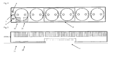
- FIGS. 4 to 6 show by way of example a device according to the invention for the detection of overvoltage with independent of the power supply data lines in the form of a power strip.
- the device has nine data lines each having an input 19 and an output 20, eg a LAN input 19 and LAN output 20.
- the contacts of the inputs 19 of the data lines and outputs 20 of the data lines are identical contacted each other electrically.
- each data line is connected to, or connected in parallel with, its own first gas discharge tube 4, which is set up to be permeable to voltage only when the predetermined limit voltage is exceeded.
- Each first gas arrester 4, which is connected to a data line is followed by its own fuse F, which is set up to interrupt when voltage is applied. On the opposite side, each fuse F is connected to ground E.
- the device further comprises a live conductor SL connected to a first voltage indicator and a neutral conductor N connected to a second voltage indicator.
- the first gas arrester 4 connected to the live conductor SL and the second gas arrester 7 connected to the neutral conductor N are followed by a common fuse F, which is connected on the opposite side to the earth E and which is arranged to interrupt when voltage is applied.
- each first gas arrester 4 which is connected to a data line, a separate fuse F is connected downstream, can first Gasableitern 4, which are connected to the data lines, also be followed by a common fuse F, which is connected at its opposite end to the ground E.
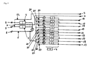
- the Fig. 7 shows a preferred embodiment of a device for detecting overvoltage with three live conductors SL and two non-voltage-carrying conductors NL, one of which is a ground E and the other is a neutral N, wherein the voltage-carrying conductors SL and the neutral conductor N are each a gas arrester 4, 7 is connected.
- the first gas outlet 4 and the second gas outlet 7 are connected at their outputs each with a fuse F, which in turn is connected at its opposite end of the gas discharge with a device for data transmission 14.
- the device for data transmission 14 is connected to a device for position determination 15.
- the data transmission device 14 and the position determination device 15 are set up to send a signal to a receiver 17 when a voltage pulse is detected, the signal transmitted by the data transmission device 14 containing an identification feature of the device, for example a serial number, and signal sent from the position-determining device 15 contains information about the location of the device at the time of detection of voltage.
- the means for data transmission 14 and the means 15 for determining the position each have a transmitter.
- the device 15 for determining the location of the device and the time of detecting voltage has a location indicator, for example a GPS receiver or a Galileo receiver.
- the device for data transmission 14 and the device for position determination 15 each preferably have a power supply.
Landscapes
- Emergency Protection Circuit Devices (AREA)
- Locating Faults (AREA)
- Protection Of Static Devices (AREA)
- Measurement Of Current Or Voltage (AREA)
Priority Applications (1)
| Application Number | Priority Date | Filing Date | Title |
|---|---|---|---|
| EP13165459.2A EP2658068B1 (fr) | 2012-04-26 | 2013-04-25 | Dispositif de détection de surtension |
Applications Claiming Priority (4)
| Application Number | Priority Date | Filing Date | Title |
|---|---|---|---|
| DE102012103702.7A DE102012103702B4 (de) | 2012-04-26 | 2012-04-26 | Vorrichtung zum Nachweis von Überspannung |
| EP12185740.3A EP2658066A1 (fr) | 2012-04-26 | 2012-09-24 | Dispositif de contrôle de surtension |
| EP13150570.3A EP2658067A1 (fr) | 2012-04-26 | 2013-01-08 | Dispositif de détection de surtension |
| EP13165459.2A EP2658068B1 (fr) | 2012-04-26 | 2013-04-25 | Dispositif de détection de surtension |
Publications (2)
| Publication Number | Publication Date |
|---|---|
| EP2658068A1 true EP2658068A1 (fr) | 2013-10-30 |
| EP2658068B1 EP2658068B1 (fr) | 2016-12-21 |
Family
ID=47216032
Family Applications (3)
| Application Number | Title | Priority Date | Filing Date |
|---|---|---|---|
| EP12185740.3A Withdrawn EP2658066A1 (fr) | 2012-04-26 | 2012-09-24 | Dispositif de contrôle de surtension |
| EP13150570.3A Withdrawn EP2658067A1 (fr) | 2012-04-26 | 2013-01-08 | Dispositif de détection de surtension |
| EP13165459.2A Not-in-force EP2658068B1 (fr) | 2012-04-26 | 2013-04-25 | Dispositif de détection de surtension |
Family Applications Before (2)
| Application Number | Title | Priority Date | Filing Date |
|---|---|---|---|
| EP12185740.3A Withdrawn EP2658066A1 (fr) | 2012-04-26 | 2012-09-24 | Dispositif de contrôle de surtension |
| EP13150570.3A Withdrawn EP2658067A1 (fr) | 2012-04-26 | 2013-01-08 | Dispositif de détection de surtension |
Country Status (2)
| Country | Link |
|---|---|
| EP (3) | EP2658066A1 (fr) |
| DE (1) | DE102012103702B4 (fr) |
Families Citing this family (1)
| Publication number | Priority date | Publication date | Assignee | Title |
|---|---|---|---|---|
| EP3285325A1 (fr) | 2016-08-19 | 2018-02-21 | Robert Bosch Gmbh | Indicateur et procédé pour prouver une occurrence d'une tension critique |
Citations (19)
| Publication number | Priority date | Publication date | Assignee | Title |
|---|---|---|---|---|
| DE1513567A1 (de) | 1956-07-26 | 1970-01-15 | Schwarz Dipl Ing Karl | Neue Schaltanordnung fuer Blitzschutz-Elemente |
| DE2813115A1 (de) | 1978-03-25 | 1979-09-27 | Rudolf Schiesser | Schaltungsanordnung zum schutz von mehrphasennetzen und verbraucheranlagen gegen ueberspannungen |
| EP0046545A1 (fr) | 1980-08-21 | 1982-03-03 | BROWN, BOVERI & CIE Aktiengesellschaft | Equipement d'installation électrique |
| EP0061652A1 (fr) | 1981-03-20 | 1982-10-06 | Heinrich Kopp GmbH & Co. KG | Dispositif de protection contre les surtensions pour installations électriques domestiques |
| DE3800018A1 (de) * | 1987-02-03 | 1989-04-13 | Wolfgang Muth | Netz - zwischenstecker zum schutz elektrischer/elektronischer verbraucher |
| DE3834868A1 (de) | 1988-10-13 | 1990-04-19 | Telefonbau & Normalzeit Gmbh | Ueberspannungsableiter |
| US5101180A (en) | 1990-11-05 | 1992-03-31 | Tycor International Inc. | Bidirectional communication line filter and surge protector |
| AU1514792A (en) | 1991-06-05 | 1992-12-10 | H.P.M. Industries Pty Limited | Electrical plug |
| EP0678961A1 (fr) | 1994-04-21 | 1995-10-25 | Felten & Guilleaume Austria Ag | Circuit reconnaissant et affichant l'interruption d'un conducteur |
| JPH0821858A (ja) * | 1993-12-28 | 1996-01-23 | Tohoku Electric Power Co Inc | サージ識別装置 |
| EP0762589A1 (fr) * | 1995-08-23 | 1997-03-12 | Van der Heide Beheer B.V. | Dispositif d'enregistrement de coups de foudre |
| DE19722580C1 (de) | 1997-05-30 | 1998-10-15 | Krone Ag | Überspannungsschutzstecker mit Fail-Safe |
| US5977762A (en) * | 1997-11-26 | 1999-11-02 | Mirage Lighting Technology Ltd | Lightning detection apparatus and methodology |
| WO2000031852A1 (fr) | 1998-11-23 | 2000-06-02 | Tii Industries, Inc. | Limiteur de surtension |
| US20020153989A1 (en) | 2000-10-26 | 2002-10-24 | Jonie Chou | Circuit for indicating abnormality of three-mode surge absorber of public electric power and a multiple-end fuse |
| DE10107357C2 (de) | 2001-02-07 | 2003-03-27 | Siemens Ag | Signaleinrichtung zur Anzeige des Ansprechens eines Überspannungsableiters |
| WO2004006408A1 (fr) * | 2002-07-02 | 2004-01-15 | Fultec Pty Ltd | Appareil de protection et d'indication |
| US20070188962A1 (en) * | 2006-02-15 | 2007-08-16 | Hubbell Incorporated | Surge protector life cycle monitor system and method |
| WO2007093217A1 (fr) | 2006-02-16 | 2007-08-23 | Telefonaktiebolaget Lm Ericsson (Publ) | Circuit de protection contre les surtensions et circuit de detection permettant de controler ce circuit de protection |
Family Cites Families (1)
| Publication number | Priority date | Publication date | Assignee | Title |
|---|---|---|---|---|
| DE1114586B (de) * | 1960-04-30 | 1961-10-05 | Zahnradfabrik Friedrichshafen | Schaltungsanordnung zum Anzeigen von UEberspannungsspitzen in einem Gleichstrom-Netz |
-
2012
- 2012-04-26 DE DE102012103702.7A patent/DE102012103702B4/de not_active Expired - Fee Related
- 2012-09-24 EP EP12185740.3A patent/EP2658066A1/fr not_active Withdrawn
-
2013
- 2013-01-08 EP EP13150570.3A patent/EP2658067A1/fr not_active Withdrawn
- 2013-04-25 EP EP13165459.2A patent/EP2658068B1/fr not_active Not-in-force
Patent Citations (21)
| Publication number | Priority date | Publication date | Assignee | Title |
|---|---|---|---|---|
| DE1513567A1 (de) | 1956-07-26 | 1970-01-15 | Schwarz Dipl Ing Karl | Neue Schaltanordnung fuer Blitzschutz-Elemente |
| DE2813115A1 (de) | 1978-03-25 | 1979-09-27 | Rudolf Schiesser | Schaltungsanordnung zum schutz von mehrphasennetzen und verbraucheranlagen gegen ueberspannungen |
| EP0046545A1 (fr) | 1980-08-21 | 1982-03-03 | BROWN, BOVERI & CIE Aktiengesellschaft | Equipement d'installation électrique |
| EP0061652A1 (fr) | 1981-03-20 | 1982-10-06 | Heinrich Kopp GmbH & Co. KG | Dispositif de protection contre les surtensions pour installations électriques domestiques |
| DE3800018A1 (de) * | 1987-02-03 | 1989-04-13 | Wolfgang Muth | Netz - zwischenstecker zum schutz elektrischer/elektronischer verbraucher |
| DE3834868A1 (de) | 1988-10-13 | 1990-04-19 | Telefonbau & Normalzeit Gmbh | Ueberspannungsableiter |
| US5101180A (en) | 1990-11-05 | 1992-03-31 | Tycor International Inc. | Bidirectional communication line filter and surge protector |
| AU1514792A (en) | 1991-06-05 | 1992-12-10 | H.P.M. Industries Pty Limited | Electrical plug |
| AU652241B2 (en) * | 1991-06-05 | 1994-08-18 | H.P.M. Industries Pty Limited | Electrical plug |
| JPH0821858A (ja) * | 1993-12-28 | 1996-01-23 | Tohoku Electric Power Co Inc | サージ識別装置 |
| EP0678961A1 (fr) | 1994-04-21 | 1995-10-25 | Felten & Guilleaume Austria Ag | Circuit reconnaissant et affichant l'interruption d'un conducteur |
| EP0762589A1 (fr) * | 1995-08-23 | 1997-03-12 | Van der Heide Beheer B.V. | Dispositif d'enregistrement de coups de foudre |
| DE19722580C1 (de) | 1997-05-30 | 1998-10-15 | Krone Ag | Überspannungsschutzstecker mit Fail-Safe |
| US5977762A (en) * | 1997-11-26 | 1999-11-02 | Mirage Lighting Technology Ltd | Lightning detection apparatus and methodology |
| WO2000031852A1 (fr) | 1998-11-23 | 2000-06-02 | Tii Industries, Inc. | Limiteur de surtension |
| US20020153989A1 (en) | 2000-10-26 | 2002-10-24 | Jonie Chou | Circuit for indicating abnormality of three-mode surge absorber of public electric power and a multiple-end fuse |
| DE10107357C2 (de) | 2001-02-07 | 2003-03-27 | Siemens Ag | Signaleinrichtung zur Anzeige des Ansprechens eines Überspannungsableiters |
| WO2004006408A1 (fr) * | 2002-07-02 | 2004-01-15 | Fultec Pty Ltd | Appareil de protection et d'indication |
| US20050180080A1 (en) | 2002-07-02 | 2005-08-18 | Fultec Semiconductor, Inc. | Protection and indication apparatus |
| US20070188962A1 (en) * | 2006-02-15 | 2007-08-16 | Hubbell Incorporated | Surge protector life cycle monitor system and method |
| WO2007093217A1 (fr) | 2006-02-16 | 2007-08-23 | Telefonaktiebolaget Lm Ericsson (Publ) | Circuit de protection contre les surtensions et circuit de detection permettant de controler ce circuit de protection |
Also Published As
| Publication number | Publication date |
|---|---|
| EP2658066A1 (fr) | 2013-10-30 |
| EP2658068B1 (fr) | 2016-12-21 |
| DE102012103702B4 (de) | 2017-08-17 |
| EP2658067A1 (fr) | 2013-10-30 |
| DE102012103702A1 (de) | 2013-10-31 |
Similar Documents
| Publication | Publication Date | Title |
|---|---|---|
| EP3867651B1 (fr) | Dispositif de mesure, installation électrique comprenant un dispositif de mesure et procédé de mesure d'un courant de fuite | |
| EP2885805B1 (fr) | Indicateur de défaillance de fusible | |
| DE102018127939A1 (de) | Intelligenter Leistungsschalter | |
| EP3273459A1 (fr) | Dispositif et procede de surveillance d'une unite d'interruption dans un reseau d'alimentation en energie electrique et station de distribution comprenant une unite d'interruption surveillee | |
| DE102022115025A1 (de) | Vorrichtung zum Schutz gegen Überspannungen umfassend einem Sensor zur Strommessung | |
| EP2695268B1 (fr) | Dispositif de protection contre les surtensions | |
| DE102008031200A1 (de) | Überspannungsschutzgerät | |
| EP3915178A1 (fr) | Dispositif de dérivation du courant de foudre | |
| DE102014017990A1 (de) | Hochvoltkomponente für ein Fahrzeug, insbesondere ein Hybrid- oder Elektrofahrzeug | |
| DE102012024352A1 (de) | Überspannungsschutzgerät | |
| DE102011017051A1 (de) | Überwachungseinrichtung für ein isoliert aufgebautes Netz einer Photovoltaikanlage | |
| EP2658068B1 (fr) | Dispositif de détection de surtension | |
| WO2016169841A1 (fr) | Embase pour dispositif de protection contre les surtensions et dispositif de protection contre les surtensions | |
| EP0173018A1 (fr) | Système d'installation électrique avec protection de surtension | |
| DE3812058A1 (de) | Anordnung fuer den ueberspannungsschutz in niederspannungsanlagen | |
| DE102011052449A1 (de) | Stromwandler sowie Lasttrenner mit einem solchen | |
| EP4439091A1 (fr) | Borne enfichable pour compteur, module et armoire de distribution | |
| EP0071956A1 (fr) | Appareil d'installation | |
| DE102014204922A1 (de) | System, insbesondere Batteriesystem, mit Potentialausgleichselement | |
| DE102013222392A1 (de) | Batteriesystem mit redundanter Strommessung und Verfahren zur Übertragung von Strommessdaten | |
| EP3211644A1 (fr) | Limiteur de surtension comprenant des moyens pour mesurer les surtensions transitoires | |
| EP0678961A1 (fr) | Circuit reconnaissant et affichant l'interruption d'un conducteur | |
| EP2991177A1 (fr) | Dispositif de protection contre la surtension | |
| DE202014103923U1 (de) | Überspannungsschutzanordnung | |
| DE19516092B4 (de) | Gefahrenmeldeanlage mit wenigstens einer Schirmleitung |
Legal Events
| Date | Code | Title | Description |
|---|---|---|---|
| PUAI | Public reference made under article 153(3) epc to a published international application that has entered the european phase |
Free format text: ORIGINAL CODE: 0009012 |
|
| AK | Designated contracting states |
Kind code of ref document: A1 Designated state(s): AL AT BE BG CH CY CZ DE DK EE ES FI FR GB GR HR HU IE IS IT LI LT LU LV MC MK MT NL NO PL PT RO RS SE SI SK SM TR |
|
| AX | Request for extension of the european patent |
Extension state: BA ME |
|
| 17P | Request for examination filed |
Effective date: 20131101 |
|
| 17Q | First examination report despatched |
Effective date: 20140210 |
|
| RAP1 | Party data changed (applicant data changed or rights of an application transferred) |
Owner name: TECHNISCHER VOR ORT SERVICE OHG |
|
| RBV | Designated contracting states (corrected) |
Designated state(s): AL AT BE BG CH CY CZ DE DK EE ES FI FR GB GR HR HU IE IS IT LI LT LU LV MC MK MT NL NO PL PT RO RS SE SI SK SM TR |
|
| REG | Reference to a national code |
Ref country code: DE Ref legal event code: R079 Ref document number: 502013005808 Country of ref document: DE Free format text: PREVIOUS MAIN CLASS: H02H0009040000 Ipc: H02H0001000000 |
|
| GRAP | Despatch of communication of intention to grant a patent |
Free format text: ORIGINAL CODE: EPIDOSNIGR1 |
|
| RIC1 | Information provided on ipc code assigned before grant |
Ipc: H02H 9/06 20060101ALI20160922BHEP Ipc: H02H 9/04 20060101ALI20160922BHEP Ipc: H02H 1/00 20060101AFI20160922BHEP |
|
| INTG | Intention to grant announced |
Effective date: 20161007 |
|
| GRAS | Grant fee paid |
Free format text: ORIGINAL CODE: EPIDOSNIGR3 |
|
| GRAA | (expected) grant |
Free format text: ORIGINAL CODE: 0009210 |
|
| AK | Designated contracting states |
Kind code of ref document: B1 Designated state(s): AL AT BE BG CH CY CZ DE DK EE ES FI FR GB GR HR HU IE IS IT LI LT LU LV MC MK MT NL NO PL PT RO RS SE SI SK SM TR |
|
| REG | Reference to a national code |
Ref country code: GB Ref legal event code: FG4D Free format text: NOT ENGLISH |
|
| REG | Reference to a national code |
Ref country code: CH Ref legal event code: EP |
|
| REG | Reference to a national code |
Ref country code: IE Ref legal event code: FG4D Free format text: LANGUAGE OF EP DOCUMENT: GERMAN |
|
| REG | Reference to a national code |
Ref country code: AT Ref legal event code: REF Ref document number: 856235 Country of ref document: AT Kind code of ref document: T Effective date: 20170115 |
|
| REG | Reference to a national code |
Ref country code: DE Ref legal event code: R082 Ref document number: 502013005808 Country of ref document: DE Representative=s name: TARUTTIS UND KOLLEGEN, DE |
|
| REG | Reference to a national code |
Ref country code: DE Ref legal event code: R096 Ref document number: 502013005808 Country of ref document: DE |
|
| PG25 | Lapsed in a contracting state [announced via postgrant information from national office to epo] |
Ref country code: LV Free format text: LAPSE BECAUSE OF FAILURE TO SUBMIT A TRANSLATION OF THE DESCRIPTION OR TO PAY THE FEE WITHIN THE PRESCRIBED TIME-LIMIT Effective date: 20161221 |
|
| REG | Reference to a national code |
Ref country code: LT Ref legal event code: MG4D |
|
| REG | Reference to a national code |
Ref country code: NL Ref legal event code: MP Effective date: 20161221 |
|
| PG25 | Lapsed in a contracting state [announced via postgrant information from national office to epo] |
Ref country code: SE Free format text: LAPSE BECAUSE OF FAILURE TO SUBMIT A TRANSLATION OF THE DESCRIPTION OR TO PAY THE FEE WITHIN THE PRESCRIBED TIME-LIMIT Effective date: 20161221 Ref country code: LT Free format text: LAPSE BECAUSE OF FAILURE TO SUBMIT A TRANSLATION OF THE DESCRIPTION OR TO PAY THE FEE WITHIN THE PRESCRIBED TIME-LIMIT Effective date: 20161221 Ref country code: NO Free format text: LAPSE BECAUSE OF FAILURE TO SUBMIT A TRANSLATION OF THE DESCRIPTION OR TO PAY THE FEE WITHIN THE PRESCRIBED TIME-LIMIT Effective date: 20170321 Ref country code: GR Free format text: LAPSE BECAUSE OF FAILURE TO SUBMIT A TRANSLATION OF THE DESCRIPTION OR TO PAY THE FEE WITHIN THE PRESCRIBED TIME-LIMIT Effective date: 20170322 |
|
| PG25 | Lapsed in a contracting state [announced via postgrant information from national office to epo] |
Ref country code: FI Free format text: LAPSE BECAUSE OF FAILURE TO SUBMIT A TRANSLATION OF THE DESCRIPTION OR TO PAY THE FEE WITHIN THE PRESCRIBED TIME-LIMIT Effective date: 20161221 Ref country code: RS Free format text: LAPSE BECAUSE OF FAILURE TO SUBMIT A TRANSLATION OF THE DESCRIPTION OR TO PAY THE FEE WITHIN THE PRESCRIBED TIME-LIMIT Effective date: 20161221 Ref country code: HR Free format text: LAPSE BECAUSE OF FAILURE TO SUBMIT A TRANSLATION OF THE DESCRIPTION OR TO PAY THE FEE WITHIN THE PRESCRIBED TIME-LIMIT Effective date: 20161221 |
|
| PG25 | Lapsed in a contracting state [announced via postgrant information from national office to epo] |
Ref country code: NL Free format text: LAPSE BECAUSE OF FAILURE TO SUBMIT A TRANSLATION OF THE DESCRIPTION OR TO PAY THE FEE WITHIN THE PRESCRIBED TIME-LIMIT Effective date: 20161221 |
|
| PG25 | Lapsed in a contracting state [announced via postgrant information from national office to epo] |
Ref country code: IS Free format text: LAPSE BECAUSE OF FAILURE TO SUBMIT A TRANSLATION OF THE DESCRIPTION OR TO PAY THE FEE WITHIN THE PRESCRIBED TIME-LIMIT Effective date: 20170421 Ref country code: SK Free format text: LAPSE BECAUSE OF FAILURE TO SUBMIT A TRANSLATION OF THE DESCRIPTION OR TO PAY THE FEE WITHIN THE PRESCRIBED TIME-LIMIT Effective date: 20161221 Ref country code: CZ Free format text: LAPSE BECAUSE OF FAILURE TO SUBMIT A TRANSLATION OF THE DESCRIPTION OR TO PAY THE FEE WITHIN THE PRESCRIBED TIME-LIMIT Effective date: 20161221 Ref country code: RO Free format text: LAPSE BECAUSE OF FAILURE TO SUBMIT A TRANSLATION OF THE DESCRIPTION OR TO PAY THE FEE WITHIN THE PRESCRIBED TIME-LIMIT Effective date: 20161221 Ref country code: EE Free format text: LAPSE BECAUSE OF FAILURE TO SUBMIT A TRANSLATION OF THE DESCRIPTION OR TO PAY THE FEE WITHIN THE PRESCRIBED TIME-LIMIT Effective date: 20161221 |
|
| PG25 | Lapsed in a contracting state [announced via postgrant information from national office to epo] |
Ref country code: IT Free format text: LAPSE BECAUSE OF FAILURE TO SUBMIT A TRANSLATION OF THE DESCRIPTION OR TO PAY THE FEE WITHIN THE PRESCRIBED TIME-LIMIT Effective date: 20161221 Ref country code: BG Free format text: LAPSE BECAUSE OF FAILURE TO SUBMIT A TRANSLATION OF THE DESCRIPTION OR TO PAY THE FEE WITHIN THE PRESCRIBED TIME-LIMIT Effective date: 20170321 Ref country code: ES Free format text: LAPSE BECAUSE OF FAILURE TO SUBMIT A TRANSLATION OF THE DESCRIPTION OR TO PAY THE FEE WITHIN THE PRESCRIBED TIME-LIMIT Effective date: 20161221 Ref country code: PL Free format text: LAPSE BECAUSE OF FAILURE TO SUBMIT A TRANSLATION OF THE DESCRIPTION OR TO PAY THE FEE WITHIN THE PRESCRIBED TIME-LIMIT Effective date: 20161221 Ref country code: PT Free format text: LAPSE BECAUSE OF FAILURE TO SUBMIT A TRANSLATION OF THE DESCRIPTION OR TO PAY THE FEE WITHIN THE PRESCRIBED TIME-LIMIT Effective date: 20170421 Ref country code: SM Free format text: LAPSE BECAUSE OF FAILURE TO SUBMIT A TRANSLATION OF THE DESCRIPTION OR TO PAY THE FEE WITHIN THE PRESCRIBED TIME-LIMIT Effective date: 20161221 |
|
| REG | Reference to a national code |
Ref country code: DE Ref legal event code: R097 Ref document number: 502013005808 Country of ref document: DE |
|
| PLBE | No opposition filed within time limit |
Free format text: ORIGINAL CODE: 0009261 |
|
| STAA | Information on the status of an ep patent application or granted ep patent |
Free format text: STATUS: NO OPPOSITION FILED WITHIN TIME LIMIT |
|
| 26N | No opposition filed |
Effective date: 20170922 |
|
| PG25 | Lapsed in a contracting state [announced via postgrant information from national office to epo] |
Ref country code: DK Free format text: LAPSE BECAUSE OF FAILURE TO SUBMIT A TRANSLATION OF THE DESCRIPTION OR TO PAY THE FEE WITHIN THE PRESCRIBED TIME-LIMIT Effective date: 20161221 |
|
| GBPC | Gb: european patent ceased through non-payment of renewal fee |
Effective date: 20170425 |
|
| REG | Reference to a national code |
Ref country code: IE Ref legal event code: MM4A |
|
| REG | Reference to a national code |
Ref country code: FR Ref legal event code: ST Effective date: 20171229 |
|
| PG25 | Lapsed in a contracting state [announced via postgrant information from national office to epo] |
Ref country code: FR Free format text: LAPSE BECAUSE OF NON-PAYMENT OF DUE FEES Effective date: 20170502 Ref country code: MC Free format text: LAPSE BECAUSE OF FAILURE TO SUBMIT A TRANSLATION OF THE DESCRIPTION OR TO PAY THE FEE WITHIN THE PRESCRIBED TIME-LIMIT Effective date: 20161221 |
|
| PG25 | Lapsed in a contracting state [announced via postgrant information from national office to epo] |
Ref country code: LU Free format text: LAPSE BECAUSE OF NON-PAYMENT OF DUE FEES Effective date: 20170425 Ref country code: GB Free format text: LAPSE BECAUSE OF NON-PAYMENT OF DUE FEES Effective date: 20170425 Ref country code: SI Free format text: LAPSE BECAUSE OF FAILURE TO SUBMIT A TRANSLATION OF THE DESCRIPTION OR TO PAY THE FEE WITHIN THE PRESCRIBED TIME-LIMIT Effective date: 20161221 |
|
| REG | Reference to a national code |
Ref country code: BE Ref legal event code: MM Effective date: 20170430 |
|
| PG25 | Lapsed in a contracting state [announced via postgrant information from national office to epo] |
Ref country code: IE Free format text: LAPSE BECAUSE OF NON-PAYMENT OF DUE FEES Effective date: 20170425 |
|
| PG25 | Lapsed in a contracting state [announced via postgrant information from national office to epo] |
Ref country code: BE Free format text: LAPSE BECAUSE OF NON-PAYMENT OF DUE FEES Effective date: 20170430 |
|
| PG25 | Lapsed in a contracting state [announced via postgrant information from national office to epo] |
Ref country code: MT Free format text: LAPSE BECAUSE OF FAILURE TO SUBMIT A TRANSLATION OF THE DESCRIPTION OR TO PAY THE FEE WITHIN THE PRESCRIBED TIME-LIMIT Effective date: 20161221 |
|
| PG25 | Lapsed in a contracting state [announced via postgrant information from national office to epo] |
Ref country code: HU Free format text: LAPSE BECAUSE OF FAILURE TO SUBMIT A TRANSLATION OF THE DESCRIPTION OR TO PAY THE FEE WITHIN THE PRESCRIBED TIME-LIMIT; INVALID AB INITIO Effective date: 20130425 |
|
| PG25 | Lapsed in a contracting state [announced via postgrant information from national office to epo] |
Ref country code: CY Free format text: LAPSE BECAUSE OF NON-PAYMENT OF DUE FEES Effective date: 20161221 |
|
| PG25 | Lapsed in a contracting state [announced via postgrant information from national office to epo] |
Ref country code: MK Free format text: LAPSE BECAUSE OF FAILURE TO SUBMIT A TRANSLATION OF THE DESCRIPTION OR TO PAY THE FEE WITHIN THE PRESCRIBED TIME-LIMIT Effective date: 20161221 |
|
| PG25 | Lapsed in a contracting state [announced via postgrant information from national office to epo] |
Ref country code: TR Free format text: LAPSE BECAUSE OF FAILURE TO SUBMIT A TRANSLATION OF THE DESCRIPTION OR TO PAY THE FEE WITHIN THE PRESCRIBED TIME-LIMIT Effective date: 20161221 |
|
| PG25 | Lapsed in a contracting state [announced via postgrant information from national office to epo] |
Ref country code: AL Free format text: LAPSE BECAUSE OF FAILURE TO SUBMIT A TRANSLATION OF THE DESCRIPTION OR TO PAY THE FEE WITHIN THE PRESCRIBED TIME-LIMIT Effective date: 20161221 |
|
| PGFP | Annual fee paid to national office [announced via postgrant information from national office to epo] |
Ref country code: CH Payment date: 20220523 Year of fee payment: 10 Ref country code: AT Payment date: 20220427 Year of fee payment: 10 |
|
| REG | Reference to a national code |
Ref country code: CH Ref legal event code: PL |
|
| REG | Reference to a national code |
Ref country code: AT Ref legal event code: MM01 Ref document number: 856235 Country of ref document: AT Kind code of ref document: T Effective date: 20230425 |
|
| PG25 | Lapsed in a contracting state [announced via postgrant information from national office to epo] |
Ref country code: LI Free format text: LAPSE BECAUSE OF NON-PAYMENT OF DUE FEES Effective date: 20230430 Ref country code: CH Free format text: LAPSE BECAUSE OF NON-PAYMENT OF DUE FEES Effective date: 20230430 Ref country code: AT Free format text: LAPSE BECAUSE OF NON-PAYMENT OF DUE FEES Effective date: 20230425 |
|
| PGFP | Annual fee paid to national office [announced via postgrant information from national office to epo] |
Ref country code: DE Payment date: 20240426 Year of fee payment: 12 |
|
| REG | Reference to a national code |
Ref country code: DE Ref legal event code: R119 Ref document number: 502013005808 Country of ref document: DE |
|
| PG25 | Lapsed in a contracting state [announced via postgrant information from national office to epo] |
Ref country code: DE Free format text: LAPSE BECAUSE OF NON-PAYMENT OF DUE FEES Effective date: 20251104 |