EP2658080B1 - Terminal mobile et son procédé de contrôle - Google Patents
Terminal mobile et son procédé de contrôle Download PDFInfo
- Publication number
- EP2658080B1 EP2658080B1 EP13001959.9A EP13001959A EP2658080B1 EP 2658080 B1 EP2658080 B1 EP 2658080B1 EP 13001959 A EP13001959 A EP 13001959A EP 2658080 B1 EP2658080 B1 EP 2658080B1
- Authority
- EP
- European Patent Office
- Prior art keywords
- mobile terminal
- magnetic field
- unit
- wireless power
- power
- Prior art date
- Legal status (The legal status is an assumption and is not a legal conclusion. Google has not performed a legal analysis and makes no representation as to the accuracy of the status listed.)
- Not-in-force
Links
Images




Classifications
-
- G—PHYSICS
- G06—COMPUTING OR CALCULATING; COUNTING
- G06F—ELECTRIC DIGITAL DATA PROCESSING
- G06F1/00—Details not covered by groups G06F3/00 - G06F13/00 and G06F21/00
- G06F1/26—Power supply means, e.g. regulation thereof
- G06F1/266—Arrangements to supply power to external peripherals either directly from the computer or under computer control, e.g. supply of power through the communication port, computer controlled power-strips
-
- H—ELECTRICITY
- H02—GENERATION; CONVERSION OR DISTRIBUTION OF ELECTRIC POWER
- H02J—ELECTRIC POWER NETWORKS; CIRCUIT ARRANGEMENTS OR SYSTEMS FOR SUPPLYING OR DISTRIBUTING ELECTRIC POWER; SYSTEMS FOR STORING ELECTRIC ENERGY
- H02J50/00—Circuit arrangements or systems for wireless supply or distribution of electric power
- H02J50/10—Circuit arrangements or systems for wireless supply or distribution of electric power using inductive coupling
-
- H—ELECTRICITY
- H02—GENERATION; CONVERSION OR DISTRIBUTION OF ELECTRIC POWER
- H02J—ELECTRIC POWER NETWORKS; CIRCUIT ARRANGEMENTS OR SYSTEMS FOR SUPPLYING OR DISTRIBUTING ELECTRIC POWER; SYSTEMS FOR STORING ELECTRIC ENERGY
- H02J50/00—Circuit arrangements or systems for wireless supply or distribution of electric power
- H02J50/10—Circuit arrangements or systems for wireless supply or distribution of electric power using inductive coupling
- H02J50/12—Circuit arrangements or systems for wireless supply or distribution of electric power using inductive coupling of the resonant type
-
- H—ELECTRICITY
- H02—GENERATION; CONVERSION OR DISTRIBUTION OF ELECTRIC POWER
- H02J—ELECTRIC POWER NETWORKS; CIRCUIT ARRANGEMENTS OR SYSTEMS FOR SUPPLYING OR DISTRIBUTING ELECTRIC POWER; SYSTEMS FOR STORING ELECTRIC ENERGY
- H02J50/00—Circuit arrangements or systems for wireless supply or distribution of electric power
- H02J50/40—Circuit arrangements or systems for wireless supply or distribution of electric power using two or more transmitting or receiving devices
-
- H—ELECTRICITY
- H02—GENERATION; CONVERSION OR DISTRIBUTION OF ELECTRIC POWER
- H02J—ELECTRIC POWER NETWORKS; CIRCUIT ARRANGEMENTS OR SYSTEMS FOR SUPPLYING OR DISTRIBUTING ELECTRIC POWER; SYSTEMS FOR STORING ELECTRIC ENERGY
- H02J50/00—Circuit arrangements or systems for wireless supply or distribution of electric power
- H02J50/70—Circuit arrangements or systems for wireless supply or distribution of electric power involving the reduction of electric, magnetic or electromagnetic leakage fields
-
- H—ELECTRICITY
- H04—ELECTRIC COMMUNICATION TECHNIQUE
- H04B—TRANSMISSION
- H04B1/00—Details of transmission systems, not covered by a single one of groups H04B3/00 - H04B13/00; Details of transmission systems not characterised by the medium used for transmission
- H04B1/38—Transceivers, i.e. devices in which transmitter and receiver form a structural unit and in which at least one part is used for functions of transmitting and receiving
- H04B1/3827—Portable transceivers
- H04B1/3883—Arrangements for mounting batteries or battery chargers
-
- H—ELECTRICITY
- H04—ELECTRIC COMMUNICATION TECHNIQUE
- H04W—WIRELESS COMMUNICATION NETWORKS
- H04W88/00—Devices specially adapted for wireless communication networks, e.g. terminals, base stations or access point devices
- H04W88/02—Terminal devices
-
- H—ELECTRICITY
- H02—GENERATION; CONVERSION OR DISTRIBUTION OF ELECTRIC POWER
- H02J—ELECTRIC POWER NETWORKS; CIRCUIT ARRANGEMENTS OR SYSTEMS FOR SUPPLYING OR DISTRIBUTING ELECTRIC POWER; SYSTEMS FOR STORING ELECTRIC ENERGY
- H02J7/00—Circuit arrangements for charging or discharging batteries or for supplying loads from batteries
- H02J7/40—Circuit arrangements for charging or discharging batteries or for supplying loads from batteries characterised by the exchange of charge or discharge related data
- H02J7/42—Circuit arrangements for charging or discharging batteries or for supplying loads from batteries characterised by the exchange of charge or discharge related data with electronic devices having internal batteries, e.g. mobile phones
-
- H—ELECTRICITY
- H04—ELECTRIC COMMUNICATION TECHNIQUE
- H04M—TELEPHONIC COMMUNICATION
- H04M1/00—Substation equipment, e.g. for use by subscribers
- H04M1/72—Mobile telephones; Cordless telephones, i.e. devices for establishing wireless links to base stations without route selection
- H04M1/724—User interfaces specially adapted for cordless or mobile telephones
- H04M1/72403—User interfaces specially adapted for cordless or mobile telephones with means for local support of applications that increase the functionality
- H04M1/72409—User interfaces specially adapted for cordless or mobile telephones with means for local support of applications that increase the functionality by interfacing with external accessories
- H04M1/72412—User interfaces specially adapted for cordless or mobile telephones with means for local support of applications that increase the functionality by interfacing with external accessories using two-way short-range wireless interfaces
Definitions
- the present invention relates to a mobile terminal, and more particularly, to a mobile terminal and controlling method thereof.
- the present invention is suitable for a wide scope of applications, it is particularly suitable for providing a wireless charging function.
- a mobile terminal can perform various functions such as facilitating data and voice communications, capturing images and video via a camera, recording audio, playing music files and outputting music via a speaker system, and displaying images and video on a display.
- Some terminals include additional functionality which supports game playing, while other terminals are also configured as multimedia players.
- mobile terminals have been configured to receive broadcast and multicast signals which permit viewing of contents, such as videos and television programs.
- terminals can be classified into mobile terminals and stationary terminals according to their degree (e.g., ease) of mobility. Further, the mobile terminals can be further classified into handheld terminals and vehicle mount terminals according to the manner of portability.
- the mobile terminal may include a chargeable battery to support its mobility or portability. However, it is often inconvenient to charge the battery.
- US 2009/039828 A1 refers to a Wireless charger which includes a rechargeable battery so that the wireless charge can be used portably to charge electronic devices.
- the wireless charger can also be programmable so that a user can select a power-transmitting protocol that is particularly suited for the electronic device being charged.
- An object of the present invention is to provide a mobile terminal and controlling method thereof, by which a power can be transmitted to another terminal capable of a wireless power reception by wireless.
- a method of controlling a mobile terminal in transceiving a power by wireless using a magnetic field, a method of controlling a mobile terminal is defined in independent claim 6.
- suffixes 'module', 'unit' and 'part' are used to denote elements in order to facilitate the disclosure only. Therefore, significant meanings or roles are not given to the suffixes themselves, and it is understood that the suffixes 'module', 'unit' and 'part' can be used together or interchangeably.
- terminals examples include mobile terminals, such as mobile phones, user equipment, smart phones, mobile computers, digital broadcast terminals, personal digital assistants, portable multimedia players (PMP) and navigators.
- PMP portable multimedia players
- navigators such as mobile phones, user equipment, smart phones, mobile computers, digital broadcast terminals, personal digital assistants, portable multimedia players (PMP) and navigators.
- PMP portable multimedia players
- FIG. 1 is a block diagram of a mobile terminal 100 in accordance with an embodiment of the present invention.
- the mobile terminal 100 includes a wireless communication unit 110, an A/V (audio/video) input unit 120, a user input unit 130, a sensing unit 140, an output unit 150, a memory 160, an interface unit 170, a controller 180, and a power supply unit 190.
- FIG. 1 shows the mobile terminal 100 having various components, but it is understood that implementing all of the illustrated components is not a requirement. More or fewer components may be implemented according to various embodiments.
- the wireless communication unit 110 typically includes one or more components which permit wireless communication between the mobile terminal 100 and a wireless communication system or network within which the mobile terminal 100 is located.
- the wireless communication unit 110 can include a broadcast receiving module 111, a mobile communication module 112, a wireless Internet module 113, a short-range communication module 114, and a position-location module 115.
- the broadcast receiving module 111 receives a broadcast signal and/or broadcast associated information from an external broadcast managing server via a broadcast channel.
- the broadcast channel may include a satellite channel and a terrestrial channel.
- At least two broadcast receiving modules 111 can be provided in the mobile terminal 100 to facilitate simultaneous reception of at least two broadcast channels or broadcast channel switching.
- the broadcast managing server is generally a server which generates and transmits a broadcast signal and/or broadcast associated information or a server which is provided with a previously generated broadcast signal and/or broadcast associated information and then transmits the provided signal or information to a terminal.
- the broadcast signal may be implemented as a TV broadcast signal, a radio broadcast signal, and/or a data broadcast signal, among other signals. If desired, the broadcast signal may further include a broadcast signal combined with a TV or radio broadcast signal.
- the broadcast associated information includes information associated with a broadcast channel, a broadcast program, or a broadcast service provider. Furthermore, the broadcast associated information can be provided via a mobile communication network. In this instance, the broadcast associated information can be received by the mobile communication module 112.
- the broadcast receiving module 111 may be configured to receive broadcast signals transmitted from various types of broadcast systems.
- broadcasting systems may include digital multimedia broadcasting-terrestrial (DMB-T), digital multimedia broadcasting-satellite (DMB-S), digital video broadcast-handheld (DVB-H), digital video broadcast-convergence of broadcasting and mobile services (DVB-CBMS), Open Mobile Alliance Broadcast (OMA-BCAST), the data broadcasting system known as media forward link only (MediaFLOTM) and integrated services digital broadcast-terrestrial (ISDB-T).
- OMA-BCAST Open Mobile Alliance Broadcast
- MediaFLOTM media forward link only
- ISDB-T integrated services digital broadcast-terrestrial
- the broadcast receiving module 111 can be configured to be suitable for other broadcasting systems as well as the above-noted digital broadcasting systems.
- the broadcast signal and/or broadcast associated information received by the broadcast receiving module 111 may be stored in a suitable device, such as the memory 160.
- the mobile communication module 112 transmits/receives wireless signals to/from one or more network entities (e.g., a base station, an external terminal, and/or a server) via a mobile network such as GSM (Global System for Mobile communications), CDMA (Code Division Multiple Access), or WCDMA (Wideband CDMA).
- a mobile network such as GSM (Global System for Mobile communications), CDMA (Code Division Multiple Access), or WCDMA (Wideband CDMA).
- GSM Global System for Mobile communications
- CDMA Code Division Multiple Access
- WCDMA Wideband CDMA
- the wireless Internet module 113 supports Internet access for the mobile terminal 100. This module may be internally or externally coupled to the mobile terminal 100.
- the wireless Internet technology can include WLAN (Wireless LAN), Wi-Fi, WibroTM (Wireless broadband), WimaxTM (World Interoperability for Microwave Access), HSDPA (High Speed Downlink Packet Access), GSM, CDMA, WCDMA, or LTE (Long Term Evolution) .
- Wireless Internet access by WibroTM, HSPDA, GSM, CDMA, WCDMA, or LTE is achieved via a mobile communication network.
- the wireless Internet module 113 may be considered as being a kind of the mobile communication module 112 to perform the wireless Internet access via the mobile communication network.
- the short-range communication module 114 facilitates relatively short-range communications. Suitable technologies for implementing this module include radio frequency identification (RFID), infrared data association (IrDA), ultra-wideband (UWB), as well as the networking technologies commonly referred to as BluetoothTM and ZigBeeTM, to name a few.
- RFID radio frequency identification
- IrDA infrared data association
- UWB ultra-wideband
- BluetoothTM and ZigBeeTM to name a few.
- the position-location module 115 identifies or otherwise obtains the location of the mobile terminal 100.
- this module may be implemented with a global positioning system (GPS) module.
- GPS global positioning system
- the GPS module 115 is able to precisely calculate current 3-dimensional position information based on at least longitude, latitude or altitude and direction (or orientation) by calculating distance information and precise time information from at least three satellites and then applying triangulation to the calculated information. Location information and time information are calculated using three satellites, and errors of the calculated location position and time information are then amended (or corrected) using another satellite.
- the GPS module 115 is able to calculate speed information by continuously calculating a real-time current location.
- the audio/video (A/V) input unit 120 is configured to provide audio or video signal input to the mobile terminal 100.
- the A/V input unit 120 includes a camera 121 and a microphone 122.
- the camera 121 receives and processes image frames of still pictures or video, which are obtained by an image sensor in a video call mode or a photographing mode. Furthermore, the processed image frames can be displayed on the display 151.
- the microphone 122 receives an external audio signal while the portable device is in a particular mode, such as phone call mode, recording mode and voice recognition. This audio signal is processed and converted into electronic audio data. The processed audio data is transformed into a format transmittable to a mobile communication base station via the mobile communication module 112 in a call mode.
- the microphone 122 typically includes assorted noise removing algorithms to remove noise generated in the course of receiving the external audio signal.
- the user input unit 130 generates input data responsive to user manipulation of an associated input device or devices.
- Examples of such devices include a keypad, a dome switch, a touchpad (e.g., static pressure/capacitance), a jog wheel, and a jog switch.
- Some of the displays can be implemented in a transparent or optical transmittive type, i.e., a transparent display.
- a representative example of the transparent display is the TOLED (transparent OLED).
- a rear configuration of the display 151 can be implemented as the optical transmittive type as well. In this configuration, a user can see an object located at the rear of a terminal body on a portion of the display 151 of the terminal body.
- the display 151 and a sensor for detecting a touch action are configured as a mutual layer structure (hereinafter called 'touchscreen')
- the display 151 is usable as an input device as well as an output device.
- the touch sensor can be configured as a touch film, a touch sheet, or a touchpad.
- the proximity sensor 141 can include one of a transmittive photoelectric sensor, a direct reflective photoelectric sensor, a mirror reflective photoelectric sensor, a radio frequency oscillation proximity sensor, an electrostatic capacity proximity sensor, a magnetic proximity sensor, and an infrared proximity sensor. If the touchscreen includes the electrostatic capacity proximity sensor, it is configured to detect the proximity of a pointer using a variation of an electric field according to the proximity of the pointer. In this configuration, the touchscreen (touch sensor) can be considered as the proximity sensor.
- an action for enabling the pointer approaching the touchscreen to be recognized as placed on the touchscreen may be named 'proximity touch' and an action of enabling the pointer to actually come into contact with the touchscreen may be named 'contact touch'.
- a position, at which the proximity touch is made to the touchscreen using the pointer may mean a position of the pointer vertically corresponding to the touchscreen when the pointer makes the proximity touch.
- the alarm unit 153 outputs a signal for announcing the occurrence of a particular event associated with the mobile terminal 100.
- Typical events include a call received, a message received and a touch input received.
- the alarm unit 153 is able to output a signal for announcing the event occurrence by way of vibration as well as video or audio signal.
- the video or audio signal can be output via the display 151 or the audio output module 152.
- the display 151 or the audio output module 152 can be regarded as a part of the alarm unit 153.
- the haptic module 154 generates various tactile effects that can be sensed by a user. Vibration is a representative one of the tactile effects generated by the haptic module 154.
- the strength and pattern of the vibration generated by the haptic module 154 are controllable. For instance, different vibrations can be output by being synthesized together or can be output in sequence.
- the haptic module 154 is able to generate various tactile effects as well as the vibration.
- the haptic module 154 may generate an effect attributed to the arrangement of pins vertically moving against a contact skin surface, an effect attributed to the injection/suction power of air though an injection/suction hole, an effect attributed to the skim over a skin surface, an effect attributed to a contact with an electrode, an effect attributed to an electrostatic force, and an effect attributed to the representation of a hot/cold sense using an endothermic or exothermic device.
- the memory 160 may be implemented using any type or combination of suitable volatile and non-volatile memory or storage devices including hard disk, random access memory (RAM), static random access memory (SRAM), electrically erasable programmable read-only memory (EEPROM), erasable programmable read-only memory (EPROM), programmable read-only memory (PROM), read-only memory (ROM), magnetic memory, flash memory, magnetic or optical disk, multimedia card micro type memory, card-type memory (e.g., SD memory or XD memory), or other similar memory or data storage device. Furthermore, the mobile terminal 100 is able to operate in association with a web storage for performing a storage function of the memory 160 on the Internet.
- RAM random access memory
- SRAM static random access memory
- EEPROM electrically erasable programmable read-only memory
- EPROM erasable programmable read-only memory
- PROM programmable read-only memory
- ROM read-only memory
- magnetic memory flash memory
- flash memory magnetic or optical disk
- the interface unit 170 may be implemented to couple the mobile terminal 100 with external devices.
- the interface unit 170 receives data from the external devices or is supplied with power and then transfers the data or power to the respective elements of the mobile terminal 100 or enables data within the mobile terminal 100 to be transferred to the external devices.
- the interface unit 170 may be configured using a wired/wireless headset port, an external charger port, a wired/wireless data port, a memory card port, a port for coupling to a device having an identity module, audio input/output ports, video input/output ports, and/or an earphone port.
- controller 180 is able to perform a pattern (or image) recognizing process for recognizing a writing input and a picture drawing input carried out on the touchscreen as characters or images, respectively.
- Various embodiments described herein may be implemented in a computer-readable medium using, for example, computer software, hardware, or some combination of computer software and hardware.
- the embodiments described herein may be implemented within one or more application specific integrated circuits (ASICs), digital signal processors (DSPs), digital signal processing devices (DSPDs), programmable logic devices (PLDs), field programmable gate arrays (FPGAs), processors, controllers, microcontrollers, microprocessors, other electronic units designed to perform the functions described herein, or a selective combination thereof.
- ASICs application specific integrated circuits
- DSPs digital signal processors
- DSPDs digital signal processing devices
- PLDs programmable logic devices
- FPGAs field programmable gate arrays
- processors controllers, microcontrollers, microprocessors, other electronic units designed to perform the functions described herein, or a selective combination thereof.
- controller 180 may also be implemented by the controller 180.
- the mobile terminal 100 illustrated in FIG. 2A has a bar type terminal body.
- the mobile terminal 100 may be implemented in a variety of different configurations. Examples of such configurations include folder-type, slide-type, rotational-type, swing-type and combinations thereof.
- the following disclosure will primarily relate to a bar-type mobile terminal 100. However, it is understood that such disclosure may apply equally to other types of mobile terminals.
- the mobile terminal 100 includes a case (a casing, housing, or cover) constituting an exterior of the mobile terminal.
- the case can be divided into a front case 101 and a rear case 102.
- Various electric/electronic parts are loaded in a space (volume) provided between the front and rear cases 101 and 102.
- at least one middle case can be further provided between the front and rear cases 101 and 102 in addition.
- a display 151, an audio output module 152, a camera 121, manipulating units 131 and 132, a microphone 122, and an interface unit 170 can be provided at the terminal body, and more particularly, at the front case 101.
- Manipulating units 131 and 132 are part of the user input unit 130 (see FIG. 1 ).
- Content input by manipulating units 131 and 132 can be divided between the two. For instance, a command such as start, end, and scroll is input to first manipulating unit 131. Furthermore, a command for a volume adjustment of sound output from the audio output module 152, or a command for a switching to a touch recognizing mode of the display 151 can be input to second manipulating unit 132.
- a broadcast signal-receiving antenna 116 can be additionally provided at the lateral side of the terminal body as well as an antenna for communication.
- the broadcast signal receiving antenna may constitute a portion of the broadcast receiving module 111 (see FIG. 1 ) and be retractable into the terminal body.
- a power supply unit 190 for supplying a power to the terminal 100 is provided at the terminal body. Furthermore, the power supply unit 190 can be configured to be built within the terminal body. Alternatively, the power supply unit 190 can be configured to be detachably connected to the terminal body.
- a touchpad 135 for detecting a touch can be additionally provided at the rear case 102.
- the touchpad 135 can be configured as a light transmittive type similar to the display 151.
- the display 151 is configured to output visual information from both of its faces, the visual information is viewable via the touchpad 135 as well.
- the information output from both of the faces can be entirely controlled by the touchpad 135.
- a display is further provided for the touchpad 135 so that a touchscreen can be provided at the rear case 102 as well.
- the touchpad 135 is activated by interconnecting with the display 151 of the front case 101.
- the touchpad 135 can be provided at the rear of the display 151 to extend parallel to the display 151.
- the touchpad 135 can have a size equal to or smaller than the size of the display 151.
- FIG. 3 is a block diagram of a wireless power transmitting unit 201 according to one embodiment of the present invention.
- the wireless power transmitting unit 201 may include a transmitting coil 2011, a transmitting circuit 2012, a transmission microcontroller unit 2013, a current detector 2014 and the like.
- the transmitting coil 2011 plays a role as an induction coil to transmit a magnetic field. If a current is applied from the transmitting circuit 2012, the transmitting coil 2012 generates a magnetic field in proportion to an amount of a current that flows by the electromagnetic induction rule. Thus, the generated magnetic field may be externally transmitted from one mobile terminal, by which energy can be transmitted to another mobile terminal.
- An output of the transmitting circuit 2012 is connected with the transmitting coil 2011 and an input of the transmitting circuit 2012 is connected to the transmission microcontroller unit 2013. Hence, the transmitting circuit 2012 receives an input of a control signal from the transmission microcontroller unit 2013 and then transmits a signal applied to the transmitting coil 2011.
- the transmission microcontroller unit (MCU) 2013 controls the transmitting circuit 2012 based on a numerical value of a current applied to the transmitting circuit 2012 from the current detector 2014.
- the overall control of the transmission microcontroller unit 2013 is performed by the controller 180.
- the transmission microcontroller unit 2013 can control an amplitude, frequency and phase of a current to be applied to the transmitting coil 2011. In this instance, based on the amount of the current detected by the current detector 2014, the transmission microcontroller unit 2013 can modify the amplitude, frequency or phase of the current.
- the controller 180 controls the transmission microcontroller unit 2013, if the wireless communication unit receives a request signal from a terminal side of wirelessly receiving a power, the controller 180 can control the transmission microcontroller unit 2013 based on the received request signal. For instance, if the power receiving terminal side makes a request for applying a signal having a current width of 1 (A), a voltage amplitude of 15 (V), and/or a frequency of 100 kHz, the wireless communication unit 110 delivers this signal to the controller 180. Based on the delivered signal, the controller 180 can transmit a control signal to the transmission microcontroller unit 2013.
- the current detector 2014 detects an amount of a current flowing into the transmitting circuit 2012 from the power supply unit 190 and then transmits the detected amount to the transmission microcontroller unit 2013.
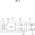
- FIG. 4 is a block diagram of a wireless power receiving unit 202 according to one embodiment of the present invention.
- the wireless power receiving unit 202 may include a receiving coil 2021, a rectifier 2022, a reception microcontroller unit 2023 and an LDO (low dropout) 2024.
- the receiving coil 2021 plays a role as an induction coil and generates an induced current using a magnetic field coming from outside. In doing so, an induced electromotive force is generated in proportion to a variation of the magnetic field by Faraday's rule and a current is generated using the electromotive force.
- the rectifier 2022 plays a role in converting the current generated from the receiving coil 2021 to a direct current.
- the rectifier 2022 converts a current generated from the receiving coil 2021 to a direct current, provides the converted current to a charger 301 to save it in a chargeable battery 302.
- the reception microcontroller unit 2023 is controlled by the controller 180 and controls the rectifier 2022. If receiving an input of a signal for charging the battery from the controller 180, the reception microcontroller unit 2023 controls the rectifier 2022 to provide the current to the charger 301.
- the LDO 2024 is connected with an output terminal to play a role in removing an excessive voltage of the output from the rectifier 2022.
- an output of the LDO 2024 is connected to the charger 301.
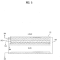
- FIG. 5 is a cross-sectional diagram of a mobile terminal and a display unit 151 thereof according to one embodiment of the present invention.
- a cross-section of the display unit 151 includes a tempered glass 501, an LCD 502, an LCD reinforcement panel 503 and a shielding member 504, which are enumerated from an outer side.
- the display unit 151 may be provided within an exterior case 506 of the mobile terminal.
- the tempered glass 501 includes a glass configured to contact with one face of the LCD 502 to protect against external shock.
- the LCD 502 is a liquid crystal display configured to display information processed by the mobile terminal 100.
- the LCD reinforcement panel 503 is the panel configured to prevent deformation of the LCD by contacting with the other face of the LCD 502.
- the transmitting coil 2011 or the receiving coil 2021 is included within the LCD reinforcement panel 503 or be positioned by contacting with the LCD reinforcement panel 503. When one of the transmitting coil 2011 and the receiving coil 2021 is positioned in this manner, the other one of the transmitting coil 2011 and the receiving coil 2021 may be situated on an opposing side 505 of the exterior case 506.
- the shielding member 504 prevents a magnetic field from flowing into an inside of the mobile terminal 100 by cutting off the magnetic field generated from the transmitting coil 2011 or the magnetic field received externally. Because the inside of the mobile terminal 100 is constructed with an integrated electric/electronic circuit, it is possible for the circuit to experience its malfunction momentarily or permanently due to the influence of the magnetic field. Thus, it is preferable to prevent the influx of the magnetic field.
- the coil in order for the transmitting coil 2011 or the receiving coil 2021 to be situated within or contact with the LCD reinforcement panel 503, the coil has a shape of a thin panel ( FIG. 6(a), FIG. 6(b) ).
- the shape of the transmitting coil 2011 or the receiving coil 2021 is non-limited by the shapes shown in FIG. 6 .
- the transmitting coil 2011 or the receiving coil 2021 does not affect an overall volume of the mobile terminal 100.
- the LCD reinforcement panel 503 is the component protecting the LCD 502, it has nothing to do with a presence or non-presence of a coil. Hence, if the coil is arranged within the LCD reinforcement panel 503, it can minimize the volume occupied by the corresponding coil.
- a magnetic field generated from a coil in accordance with a material of the LCD reinforcement panel 503.
- a material of the LCD reinforcement panel 503 includes a magnetic body
- a coil is arranged within or in the vicinity of the magnetic body, a magnetic field generated from the coil can be focused or an externally received magnetic field can be focused on the corresponding coil.
- the transmitting coil 2011 or the receiving coil 2021 may supplement a role of the LCD reinforcement panel 503 using the rigidity of the coil together with the rigidity of the LCD reinforcement panel 503.
- the transmitting coil 2011 or the receiving coil 2021 may be provided to different locations, respectively.
- the other may be situated at the opposing side 505 of the exterior case 506.
- FIG. 7B shows that the mobile terminal 100 generates a magnetic field on its own.
- the mobile terminal 100 receives a power by wireless using a magnetic field generated by the wireless charging pad 701 and simultaneously generates a magnetic field (hereinafter named a 2 nd magnetic field) 704 on its own to transmit energy to the 2 nd mobile terminal 100'.
- the 2 nd magnetic field 704 is being generated by applying a current to the transmitting coil 2011 situated within the 1 st mobile terminal 100. If the 2 nd mobile terminal 100' is placed at the location of generating the 2 nd magnetic field 704 as shown in FIG.
- FIG. 8 is a diagram to describe a method for one mobile terminal (hereinafter named a 1 st mobile terminal) 100 to transmit a power to another terminal (hereinafter named a 2 nd mobile terminal) 100' by wireless transmission according to one embodiment of the present invention.
- the 1 st mobile terminal 100 generates a magnetic field 801 from the transmitting coil 2011 of the wireless power transmitting unit 201.
- the magnetic field 801 is generated by the wireless power transmitting unit 201 controlling a current to flow in the transmitting coil 2011 by the electromagnetic induction rule.
- the generated magnetic field 801 is unable to penetrate the 2 nd mobile terminal 100'.
- the generated magnetic field 801 is unable to penetrate the 2 nd mobile terminal 100'.
- it is unable to charge the mobile terminals 100 simultaneously.
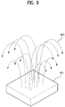
- the portable charging device 901 may not need a terminal for a charging. As the portable charging device 901 does not have the charging terminal, it may be facilitated to have a waterproof function. If a waterproof structure is further provided to the portable charging device 901, a waterproof level of the portable charging device 901 may be raised.
Landscapes
- Engineering & Computer Science (AREA)
- Computer Networks & Wireless Communication (AREA)
- Power Engineering (AREA)
- Physics & Mathematics (AREA)
- Theoretical Computer Science (AREA)
- General Engineering & Computer Science (AREA)
- Signal Processing (AREA)
- General Physics & Mathematics (AREA)
- Computer Hardware Design (AREA)
- Electromagnetism (AREA)
- Charge And Discharge Circuits For Batteries Or The Like (AREA)
- Telephone Function (AREA)
- Near-Field Transmission Systems (AREA)
Claims (9)
- Terminal mobile (100), comprenant :une unité d'affichage (151) ;une unité d'alimentation électrique (190) comprenant une batterie rechargeable ;une unité de transmission d'énergie sans fil (2011, 2012) configurée pour transformer l'énergie fournie à partir de la batterie en un champ magnétique, et pour transmettre le champ magnétique à au moins un autre terminal placé à une distance prédéterminée du terminal mobile (100) ; etun dispositif de commande (180) configuré pour commander une quantité d'énergie fournie à partir de la batterie à l'unité de transmission d'énergie sans fil (2011, 2012),caractérisé en ce qu'il comprend :un panneau de renforcement (503) configuré pour empêcher la déformation de l'unité d'affichage (151) par mise en contact avec une surface de l'unité d'affichage (151) ; etl'unité de transmission d'énergie sans fil (2011, 2012) étant configurée pour transformer l'énergie fournie à partir de la batterie en le champ magnétique par application d'un courant sur un fil à bobiner (2011) agencé dans le panneau de renforcement (503) ou mise en contact avec une surface du panneau de renforcement (503).
- Terminal mobile (100) selon la revendication 1, dans lequel le panneau de renforcement comprend un corps magnétique en ferrite.
- Terminal mobile (100) selon la revendication 1, comprenant en outre :une unité de réception d'énergie sans fil configurée pour recevoir un champ magnétique externe et pour transformer le champ magnétique reçu de manière externe en l'énergie,le dispositif de commande étant en outre configuré pour charger la batterie avec l'énergie transformée par l'unité de réception d'énergie sans fil.
- Terminal mobile (100) selon la revendication 3, dans lequel l'unité de réception d'énergie sans fil est en outre configurée pour recevoir le champ magnétique externe par l'intermédiaire d'un fil en forme de bobine (2021), pour générer une tension et un courant induits dans le fil en forme de bobine, puis pour transformer la tension et le courant en l'énergie utilisée pour charger la batterie.
- Terminal mobile (100) selon la revendication 4, dans lequel l'unité de transmission d'énergie sans fil (2011, 2012) est en outre configurée pour transformer l'énergie fournie à partir de la batterie chargée en le champ magnétique et audit au moins un autre terminal, et
l'unité de réception d'énergie sans fil recevant le champ magnétique externe à partir d'un plot de charge dans lequel le terminal mobile (100) est placé au-dessus du plot de charge, et transmettant le champ magnétique audit au moins un autre terminal superposé avec le terminal mobile (100) et le plot de charge. - Procédé de commande d'un terminal mobile (100), le procédé comprenant :fournir de l'énergie au terminal mobile (100) par l'intermédiaire d'une unité d'alimentation électrique comprenant une batterie rechargeable ;transformer, par l'intermédiaire d'une unité de transmission d'énergie sans fil (2011, 2012) du terminal mobile (100), l'énergie fournie à partir de la batterie en un champ magnétique ;transmettre, par l'intermédiaire de l'unité de transmission d'énergie sans fil (2011, 2012), le champ magnétique à au moins un autre terminal placé à une distance prédéterminée du terminal mobile (100) ; etcommander, par l'intermédiaire d'un dispositif de commande du terminal mobile (100), une quantité d'énergie fournie à partir de la batterie à l'unité de transmission d'énergie sans fil (2011, 2012),le terminal mobile (100) comprenant une unité d'affichage (151) et un panneau de renforcement (503) configuré pour empêcher la déformation de l'unité d'affichage (151) par mise en contact avec une surface de l'unité d'affichage (151), etl'unité de transmission d'énergie sans fil (2011, 2012) transformant l'énergie fournie à partir de la batterie en le champ magnétique par application d'un courant sur un fil à bobiner (2011) agencé dans le panneau de renforcement (503) ou mise en contact avec une surface du panneau de renforcement (503).
- Procédé selon la revendication 6, dans lequel le panneau de renforcement comprend un corps magnétique en ferrite.
- Procédé selon la revendication 6, comprenant en outre :recevoir, par l'intermédiaire d'une unité de réception d'énergie sans fil du terminal mobile (100), un champ magnétique externe et transformer le champ magnétique reçu de manière externe en l'énergie ;charger la batterie avec l'énergie transformée par l'unité de réception d'énergie sans fil ;recevoir, par l'intermédiaire de l'unité de réception d'énergie sans fil, le champ magnétique externe par l'intermédiaire d'un fil en forme de bobine (2021) ;générer une tension et un courant induits dans le fil en forme de bobine ; ettransformer la tension et le courant en l'énergie utilisée pour charger la batterie.
- Procédé selon la revendication 8, comprenant en outre :transformer, par l'intermédiaire de l'unité de transmission d'énergie sans fil (2011, 2012), l'énergie fournie à partir de la batterie chargée en le champ magnétique et transmettre le champ magnétique audit au moins un autre terminal ; etrecevoir, par l'intermédiaire de l'unité de réception d'énergie sans fil, le champ magnétique externe à partir d'un plot de charge dans lequel le terminal mobile (100) est placé au-dessus du plot de charge,ledit au moins un autre terminal étant superposé avec le terminal mobile (100) et le plot de charge.
Applications Claiming Priority (1)
| Application Number | Priority Date | Filing Date | Title |
|---|---|---|---|
| KR1020120042707A KR101890625B1 (ko) | 2012-04-24 | 2012-04-24 | 무선 충전 기능을 제공하는 이동 단말기 및 그 제어방법 |
Publications (3)
| Publication Number | Publication Date |
|---|---|
| EP2658080A2 EP2658080A2 (fr) | 2013-10-30 |
| EP2658080A3 EP2658080A3 (fr) | 2017-05-17 |
| EP2658080B1 true EP2658080B1 (fr) | 2019-01-23 |
Family
ID=48463657
Family Applications (1)
| Application Number | Title | Priority Date | Filing Date |
|---|---|---|---|
| EP13001959.9A Not-in-force EP2658080B1 (fr) | 2012-04-24 | 2013-04-15 | Terminal mobile et son procédé de contrôle |
Country Status (3)
| Country | Link |
|---|---|
| US (1) | US8798538B2 (fr) |
| EP (1) | EP2658080B1 (fr) |
| KR (1) | KR101890625B1 (fr) |
Families Citing this family (15)
| Publication number | Priority date | Publication date | Assignee | Title |
|---|---|---|---|---|
| CN202513644U (zh) * | 2012-03-23 | 2012-10-31 | 力新创展电子(香港)有限公司 | 一种可无线充电的可携带的系统 |
| KR101339486B1 (ko) * | 2012-03-29 | 2013-12-10 | 삼성전기주식회사 | 박막 코일 및 이를 구비하는 전자 기기 |
| US9218031B2 (en) * | 2012-05-18 | 2015-12-22 | Dell Products, Lp | System and method for providing wireless power feedback in a wireless power delivery system |
| KR102032560B1 (ko) * | 2013-02-05 | 2019-10-15 | 지이 하이브리드 테크놀로지스, 엘엘씨 | 저발열 무선 전력 수신 장치 및 방법 |
| US20150115881A1 (en) * | 2013-10-25 | 2015-04-30 | Samsung Electro-Mechanics Co., Ltd. | Wireless power transceiver and portable terminal having the same |
| US10312731B2 (en) * | 2014-04-24 | 2019-06-04 | Westrock Shared Services, Llc | Powered shelf system for inductively powering electrical components of consumer product packages |
| US9991753B2 (en) * | 2014-06-11 | 2018-06-05 | Enovate Medical Llc | Variable wireless transfer |
| KR102332621B1 (ko) * | 2014-11-21 | 2021-12-01 | 삼성전자주식회사 | 신호 송수신 회로 및 이를 포함하는 전자 장치 |
| KR102341531B1 (ko) | 2014-12-24 | 2021-12-21 | 삼성전자 주식회사 | 전자장치의 충전 장치 및 방법 |
| KR102210514B1 (ko) | 2015-09-11 | 2021-02-02 | 삼성전자주식회사 | 무선 전력 수신기 및 무선 전력 송신기 |
| JP6686517B2 (ja) * | 2016-02-22 | 2020-04-22 | セイコーエプソン株式会社 | 電子機器および送り量補正方法 |
| EP3477811A1 (fr) | 2017-10-31 | 2019-05-01 | HMD global Oy | Fonction de chargement sans fil pour dispositif sans fil et procédé de chargement sans fil ayant une fonction d'attente |
| US10790711B2 (en) * | 2017-12-21 | 2020-09-29 | Korea Advanced Institute Of Science And Technology | Magnetic field generating apparatus having cannon shape and magnetic field generation method thereof |
| CN108183523A (zh) * | 2017-12-29 | 2018-06-19 | 宁夏软件工程院有限公司 | 一种无线充电装置 |
| KR102704043B1 (ko) | 2019-09-27 | 2024-09-09 | 삼성전자주식회사 | 무선 전력 송수신 장치 및 그 동작 방법 |
Family Cites Families (7)
| Publication number | Priority date | Publication date | Assignee | Title |
|---|---|---|---|---|
| JP2005143181A (ja) * | 2003-11-05 | 2005-06-02 | Seiko Epson Corp | 非接触電力伝送装置 |
| US8193764B2 (en) * | 2007-08-08 | 2012-06-05 | Jay Marketing Associates, Inc. | Wireless charging of electronic devices |
| US7969177B2 (en) * | 2008-12-22 | 2011-06-28 | LTX—Credence Corporation | System and method for thermal limit control |
| JP5424459B2 (ja) * | 2009-03-05 | 2014-02-26 | パナソニック株式会社 | 電子機器 |
| US9153855B2 (en) * | 2009-08-28 | 2015-10-06 | Panasonic Intellectual Property Management Co., Ltd. | Antenna, antenna unit, and communication device using them |
| KR101001752B1 (ko) * | 2010-09-17 | 2010-12-15 | 박한종 | 스마트폰용 보호장치 |
| US20130026981A1 (en) * | 2011-07-28 | 2013-01-31 | Broadcom Corporation | Dual mode wireless power |
-
2012
- 2012-04-24 KR KR1020120042707A patent/KR101890625B1/ko not_active Expired - Fee Related
- 2012-12-18 US US13/718,712 patent/US8798538B2/en not_active Expired - Fee Related
-
2013
- 2013-04-15 EP EP13001959.9A patent/EP2658080B1/fr not_active Not-in-force
Non-Patent Citations (1)
| Title |
|---|
| None * |
Also Published As
| Publication number | Publication date |
|---|---|
| US8798538B2 (en) | 2014-08-05 |
| US20130281160A1 (en) | 2013-10-24 |
| KR101890625B1 (ko) | 2018-08-22 |
| KR20130119701A (ko) | 2013-11-01 |
| EP2658080A3 (fr) | 2017-05-17 |
| EP2658080A2 (fr) | 2013-10-30 |
Similar Documents
| Publication | Publication Date | Title |
|---|---|---|
| EP2658080B1 (fr) | Terminal mobile et son procédé de contrôle | |
| EP2648274B1 (fr) | Antenne et terminal mobile utilisant l`antenne | |
| US8825118B2 (en) | Mobile terminal and method for controlling the same | |
| US8575890B2 (en) | Mobile terminal having recharge menu setting function and inter-recharging method using the same | |
| US9880701B2 (en) | Mobile terminal and controlling method thereof | |
| US9405455B2 (en) | Mobile terminal and controlling method thereof | |
| US9678648B2 (en) | Mobile terminal and controlling method thereof | |
| EP2424200B1 (fr) | Terminal mobile et son procédé de commande | |
| US9459708B2 (en) | Mobile terminal and controlling method thereof | |
| EP2680204A2 (fr) | Terminal mobile et son procédé de contrôle | |
| EP2879037A1 (fr) | Terminal mobile et son procédé de contrôle | |
| US9195273B2 (en) | Detachable dual mobile terminal | |
| US20110022203A1 (en) | Method for executing menu in mobile terminal and mobile terminal thereof | |
| KR102046118B1 (ko) | 이동 단말기 및 그 제어 방법 | |
| KR20090059507A (ko) | 충전상태 표시기능을 갖는 무접점 충전장치 및 그 충전방법 | |
| US20170118413A1 (en) | Mobile terminal and method for controling same | |
| US20110039534A1 (en) | Method for controlling mobile terminal and mobile terminal thereof | |
| EP2846523A1 (fr) | Terminal mobile et son procédé de contrôle | |
| US8483708B2 (en) | Mobile terminal and corresponding method for transmitting new position information to counterpart terminal | |
| EP2629494B1 (fr) | Terminal mobile avec un couvercle équipé d'un circuit | |
| US9973636B2 (en) | Mobile terminal | |
| EP2312814A2 (fr) | Procédé pour joindre des données et terminal mobile correspondant |
Legal Events
| Date | Code | Title | Description |
|---|---|---|---|
| PUAI | Public reference made under article 153(3) epc to a published international application that has entered the european phase |
Free format text: ORIGINAL CODE: 0009012 |
|
| 17P | Request for examination filed |
Effective date: 20130415 |
|
| AK | Designated contracting states |
Kind code of ref document: A2 Designated state(s): AL AT BE BG CH CY CZ DE DK EE ES FI FR GB GR HR HU IE IS IT LI LT LU LV MC MK MT NL NO PL PT RO RS SE SI SK SM TR |
|
| AX | Request for extension of the european patent |
Extension state: BA ME |
|
| PUAL | Search report despatched |
Free format text: ORIGINAL CODE: 0009013 |
|
| AK | Designated contracting states |
Kind code of ref document: A3 Designated state(s): AL AT BE BG CH CY CZ DE DK EE ES FI FR GB GR HR HU IE IS IT LI LT LU LV MC MK MT NL NO PL PT RO RS SE SI SK SM TR |
|
| AX | Request for extension of the european patent |
Extension state: BA ME |
|
| RIC1 | Information provided on ipc code assigned before grant |
Ipc: H02J 17/00 00000000ALI20170410BHEP Ipc: H02J 7/02 20160101AFI20170410BHEP Ipc: H04M 1/725 20060101ALI20170410BHEP Ipc: G06F 1/26 20060101ALI20170410BHEP |
|
| REG | Reference to a national code |
Ref country code: DE Ref legal event code: R079 Ref document number: 602013050088 Country of ref document: DE Free format text: PREVIOUS MAIN CLASS: H02J0007020000 Ipc: H04B0001388300 |
|
| GRAP | Despatch of communication of intention to grant a patent |
Free format text: ORIGINAL CODE: EPIDOSNIGR1 |
|
| STAA | Information on the status of an ep patent application or granted ep patent |
Free format text: STATUS: GRANT OF PATENT IS INTENDED |
|
| RIC1 | Information provided on ipc code assigned before grant |
Ipc: H02J 50/70 20160101ALI20180801BHEP Ipc: G06F 1/26 20060101ALI20180801BHEP Ipc: H04M 1/725 20060101ALI20180801BHEP Ipc: H02J 50/12 20160101ALI20180801BHEP Ipc: H02J 50/40 20160101ALI20180801BHEP Ipc: H02J 50/10 20160101ALI20180801BHEP Ipc: H02J 7/02 20160101ALI20180801BHEP Ipc: H04B 1/3883 20150101AFI20180801BHEP |
|
| INTG | Intention to grant announced |
Effective date: 20180820 |
|
| GRAS | Grant fee paid |
Free format text: ORIGINAL CODE: EPIDOSNIGR3 |
|
| GRAA | (expected) grant |
Free format text: ORIGINAL CODE: 0009210 |
|
| STAA | Information on the status of an ep patent application or granted ep patent |
Free format text: STATUS: THE PATENT HAS BEEN GRANTED |
|
| AK | Designated contracting states |
Kind code of ref document: B1 Designated state(s): AL AT BE BG CH CY CZ DE DK EE ES FI FR GB GR HR HU IE IS IT LI LT LU LV MC MK MT NL NO PL PT RO RS SE SI SK SM TR |
|
| REG | Reference to a national code |
Ref country code: GB Ref legal event code: FG4D |
|
| REG | Reference to a national code |
Ref country code: CH Ref legal event code: EP |
|
| REG | Reference to a national code |
Ref country code: AT Ref legal event code: REF Ref document number: 1092271 Country of ref document: AT Kind code of ref document: T Effective date: 20190215 |
|
| REG | Reference to a national code |
Ref country code: IE Ref legal event code: FG4D |
|
| REG | Reference to a national code |
Ref country code: DE Ref legal event code: R096 Ref document number: 602013050088 Country of ref document: DE |
|
| REG | Reference to a national code |
Ref country code: NL Ref legal event code: MP Effective date: 20190123 |
|
| PG25 | Lapsed in a contracting state [announced via postgrant information from national office to epo] |
Ref country code: NL Free format text: LAPSE BECAUSE OF FAILURE TO SUBMIT A TRANSLATION OF THE DESCRIPTION OR TO PAY THE FEE WITHIN THE PRESCRIBED TIME-LIMIT Effective date: 20190123 |
|
| PG25 | Lapsed in a contracting state [announced via postgrant information from national office to epo] |
Ref country code: NO Free format text: LAPSE BECAUSE OF FAILURE TO SUBMIT A TRANSLATION OF THE DESCRIPTION OR TO PAY THE FEE WITHIN THE PRESCRIBED TIME-LIMIT Effective date: 20190423 Ref country code: FI Free format text: LAPSE BECAUSE OF FAILURE TO SUBMIT A TRANSLATION OF THE DESCRIPTION OR TO PAY THE FEE WITHIN THE PRESCRIBED TIME-LIMIT Effective date: 20190123 Ref country code: PT Free format text: LAPSE BECAUSE OF FAILURE TO SUBMIT A TRANSLATION OF THE DESCRIPTION OR TO PAY THE FEE WITHIN THE PRESCRIBED TIME-LIMIT Effective date: 20190523 Ref country code: SE Free format text: LAPSE BECAUSE OF FAILURE TO SUBMIT A TRANSLATION OF THE DESCRIPTION OR TO PAY THE FEE WITHIN THE PRESCRIBED TIME-LIMIT Effective date: 20190123 Ref country code: LT Free format text: LAPSE BECAUSE OF FAILURE TO SUBMIT A TRANSLATION OF THE DESCRIPTION OR TO PAY THE FEE WITHIN THE PRESCRIBED TIME-LIMIT Effective date: 20190123 Ref country code: ES Free format text: LAPSE BECAUSE OF FAILURE TO SUBMIT A TRANSLATION OF THE DESCRIPTION OR TO PAY THE FEE WITHIN THE PRESCRIBED TIME-LIMIT Effective date: 20190123 Ref country code: PL Free format text: LAPSE BECAUSE OF FAILURE TO SUBMIT A TRANSLATION OF THE DESCRIPTION OR TO PAY THE FEE WITHIN THE PRESCRIBED TIME-LIMIT Effective date: 20190123 |
|
| REG | Reference to a national code |
Ref country code: AT Ref legal event code: MK05 Ref document number: 1092271 Country of ref document: AT Kind code of ref document: T Effective date: 20190123 |
|
| PG25 | Lapsed in a contracting state [announced via postgrant information from national office to epo] |
Ref country code: HR Free format text: LAPSE BECAUSE OF FAILURE TO SUBMIT A TRANSLATION OF THE DESCRIPTION OR TO PAY THE FEE WITHIN THE PRESCRIBED TIME-LIMIT Effective date: 20190123 Ref country code: RS Free format text: LAPSE BECAUSE OF FAILURE TO SUBMIT A TRANSLATION OF THE DESCRIPTION OR TO PAY THE FEE WITHIN THE PRESCRIBED TIME-LIMIT Effective date: 20190123 Ref country code: LV Free format text: LAPSE BECAUSE OF FAILURE TO SUBMIT A TRANSLATION OF THE DESCRIPTION OR TO PAY THE FEE WITHIN THE PRESCRIBED TIME-LIMIT Effective date: 20190123 Ref country code: GR Free format text: LAPSE BECAUSE OF FAILURE TO SUBMIT A TRANSLATION OF THE DESCRIPTION OR TO PAY THE FEE WITHIN THE PRESCRIBED TIME-LIMIT Effective date: 20190424 Ref country code: IS Free format text: LAPSE BECAUSE OF FAILURE TO SUBMIT A TRANSLATION OF THE DESCRIPTION OR TO PAY THE FEE WITHIN THE PRESCRIBED TIME-LIMIT Effective date: 20190523 Ref country code: BG Free format text: LAPSE BECAUSE OF FAILURE TO SUBMIT A TRANSLATION OF THE DESCRIPTION OR TO PAY THE FEE WITHIN THE PRESCRIBED TIME-LIMIT Effective date: 20190423 |
|
| REG | Reference to a national code |
Ref country code: DE Ref legal event code: R097 Ref document number: 602013050088 Country of ref document: DE |
|
| PG25 | Lapsed in a contracting state [announced via postgrant information from national office to epo] |
Ref country code: EE Free format text: LAPSE BECAUSE OF FAILURE TO SUBMIT A TRANSLATION OF THE DESCRIPTION OR TO PAY THE FEE WITHIN THE PRESCRIBED TIME-LIMIT Effective date: 20190123 Ref country code: DK Free format text: LAPSE BECAUSE OF FAILURE TO SUBMIT A TRANSLATION OF THE DESCRIPTION OR TO PAY THE FEE WITHIN THE PRESCRIBED TIME-LIMIT Effective date: 20190123 Ref country code: CZ Free format text: LAPSE BECAUSE OF FAILURE TO SUBMIT A TRANSLATION OF THE DESCRIPTION OR TO PAY THE FEE WITHIN THE PRESCRIBED TIME-LIMIT Effective date: 20190123 Ref country code: RO Free format text: LAPSE BECAUSE OF FAILURE TO SUBMIT A TRANSLATION OF THE DESCRIPTION OR TO PAY THE FEE WITHIN THE PRESCRIBED TIME-LIMIT Effective date: 20190123 Ref country code: IT Free format text: LAPSE BECAUSE OF FAILURE TO SUBMIT A TRANSLATION OF THE DESCRIPTION OR TO PAY THE FEE WITHIN THE PRESCRIBED TIME-LIMIT Effective date: 20190123 Ref country code: SK Free format text: LAPSE BECAUSE OF FAILURE TO SUBMIT A TRANSLATION OF THE DESCRIPTION OR TO PAY THE FEE WITHIN THE PRESCRIBED TIME-LIMIT Effective date: 20190123 Ref country code: AL Free format text: LAPSE BECAUSE OF FAILURE TO SUBMIT A TRANSLATION OF THE DESCRIPTION OR TO PAY THE FEE WITHIN THE PRESCRIBED TIME-LIMIT Effective date: 20190123 |
|
| PG25 | Lapsed in a contracting state [announced via postgrant information from national office to epo] |
Ref country code: SM Free format text: LAPSE BECAUSE OF FAILURE TO SUBMIT A TRANSLATION OF THE DESCRIPTION OR TO PAY THE FEE WITHIN THE PRESCRIBED TIME-LIMIT Effective date: 20190123 |
|
| REG | Reference to a national code |
Ref country code: CH Ref legal event code: PL |
|
| PLBE | No opposition filed within time limit |
Free format text: ORIGINAL CODE: 0009261 |
|
| STAA | Information on the status of an ep patent application or granted ep patent |
Free format text: STATUS: NO OPPOSITION FILED WITHIN TIME LIMIT |
|
| REG | Reference to a national code |
Ref country code: BE Ref legal event code: MM Effective date: 20190430 |
|
| GBPC | Gb: european patent ceased through non-payment of renewal fee |
Effective date: 20190423 |
|
| PG25 | Lapsed in a contracting state [announced via postgrant information from national office to epo] |
Ref country code: AT Free format text: LAPSE BECAUSE OF FAILURE TO SUBMIT A TRANSLATION OF THE DESCRIPTION OR TO PAY THE FEE WITHIN THE PRESCRIBED TIME-LIMIT Effective date: 20190123 Ref country code: MC Free format text: LAPSE BECAUSE OF FAILURE TO SUBMIT A TRANSLATION OF THE DESCRIPTION OR TO PAY THE FEE WITHIN THE PRESCRIBED TIME-LIMIT Effective date: 20190123 Ref country code: LU Free format text: LAPSE BECAUSE OF NON-PAYMENT OF DUE FEES Effective date: 20190415 |
|
| 26N | No opposition filed |
Effective date: 20191024 |
|
| PG25 | Lapsed in a contracting state [announced via postgrant information from national office to epo] |
Ref country code: CH Free format text: LAPSE BECAUSE OF NON-PAYMENT OF DUE FEES Effective date: 20190430 Ref country code: LI Free format text: LAPSE BECAUSE OF NON-PAYMENT OF DUE FEES Effective date: 20190430 Ref country code: GB Free format text: LAPSE BECAUSE OF NON-PAYMENT OF DUE FEES Effective date: 20190423 |
|
| PG25 | Lapsed in a contracting state [announced via postgrant information from national office to epo] |
Ref country code: SI Free format text: LAPSE BECAUSE OF FAILURE TO SUBMIT A TRANSLATION OF THE DESCRIPTION OR TO PAY THE FEE WITHIN THE PRESCRIBED TIME-LIMIT Effective date: 20190123 Ref country code: BE Free format text: LAPSE BECAUSE OF NON-PAYMENT OF DUE FEES Effective date: 20190430 |
|
| PG25 | Lapsed in a contracting state [announced via postgrant information from national office to epo] |
Ref country code: TR Free format text: LAPSE BECAUSE OF FAILURE TO SUBMIT A TRANSLATION OF THE DESCRIPTION OR TO PAY THE FEE WITHIN THE PRESCRIBED TIME-LIMIT Effective date: 20190123 |
|
| PG25 | Lapsed in a contracting state [announced via postgrant information from national office to epo] |
Ref country code: IE Free format text: LAPSE BECAUSE OF NON-PAYMENT OF DUE FEES Effective date: 20190415 |
|
| PGFP | Annual fee paid to national office [announced via postgrant information from national office to epo] |
Ref country code: FR Payment date: 20200306 Year of fee payment: 8 |
|
| PGFP | Annual fee paid to national office [announced via postgrant information from national office to epo] |
Ref country code: DE Payment date: 20200305 Year of fee payment: 8 |
|
| PG25 | Lapsed in a contracting state [announced via postgrant information from national office to epo] |
Ref country code: CY Free format text: LAPSE BECAUSE OF FAILURE TO SUBMIT A TRANSLATION OF THE DESCRIPTION OR TO PAY THE FEE WITHIN THE PRESCRIBED TIME-LIMIT Effective date: 20190123 |
|
| PG25 | Lapsed in a contracting state [announced via postgrant information from national office to epo] |
Ref country code: HU Free format text: LAPSE BECAUSE OF FAILURE TO SUBMIT A TRANSLATION OF THE DESCRIPTION OR TO PAY THE FEE WITHIN THE PRESCRIBED TIME-LIMIT; INVALID AB INITIO Effective date: 20130415 Ref country code: MT Free format text: LAPSE BECAUSE OF FAILURE TO SUBMIT A TRANSLATION OF THE DESCRIPTION OR TO PAY THE FEE WITHIN THE PRESCRIBED TIME-LIMIT Effective date: 20190123 |
|
| REG | Reference to a national code |
Ref country code: DE Ref legal event code: R119 Ref document number: 602013050088 Country of ref document: DE |
|
| PG25 | Lapsed in a contracting state [announced via postgrant information from national office to epo] |
Ref country code: FR Free format text: LAPSE BECAUSE OF NON-PAYMENT OF DUE FEES Effective date: 20210430 Ref country code: DE Free format text: LAPSE BECAUSE OF NON-PAYMENT OF DUE FEES Effective date: 20211103 |
|
| PG25 | Lapsed in a contracting state [announced via postgrant information from national office to epo] |
Ref country code: MK Free format text: LAPSE BECAUSE OF FAILURE TO SUBMIT A TRANSLATION OF THE DESCRIPTION OR TO PAY THE FEE WITHIN THE PRESCRIBED TIME-LIMIT Effective date: 20190123 |