EP2659149B1 - Vorrichtung zum gegenseitigen verriegeln zweier gleitbare montierbarer rohre - Google Patents
Vorrichtung zum gegenseitigen verriegeln zweier gleitbare montierbarer rohre Download PDFInfo
- Publication number
- EP2659149B1 EP2659149B1 EP11712954.4A EP11712954A EP2659149B1 EP 2659149 B1 EP2659149 B1 EP 2659149B1 EP 11712954 A EP11712954 A EP 11712954A EP 2659149 B1 EP2659149 B1 EP 2659149B1
- Authority
- EP
- European Patent Office
- Prior art keywords
- tube
- cams
- locking device
- rod
- pivot
- Prior art date
- Legal status (The legal status is an assumption and is not a legal conclusion. Google has not performed a legal analysis and makes no representation as to the accuracy of the status listed.)
- Active
Links
Images


Classifications
-
- B—PERFORMING OPERATIONS; TRANSPORTING
- B62—LAND VEHICLES FOR TRAVELLING OTHERWISE THAN ON RAILS
- B62K—CYCLES; CYCLE FRAMES; CYCLE STEERING DEVICES; RIDER-OPERATED TERMINAL CONTROLS SPECIALLY ADAPTED FOR CYCLES; CYCLE AXLE SUSPENSIONS; CYCLE SIDECARS, FORECARS, OR THE LIKE
- B62K19/00—Cycle frames
- B62K19/30—Frame parts shaped to receive other cycle parts or accessories
- B62K19/36—Frame parts shaped to receive other cycle parts or accessories for attaching saddle pillars, e.g. adjustable during ride
-
- B—PERFORMING OPERATIONS; TRANSPORTING
- B62—LAND VEHICLES FOR TRAVELLING OTHERWISE THAN ON RAILS
- B62J—CYCLE SADDLES OR SEATS; AUXILIARY DEVICES OR ACCESSORIES SPECIALLY ADAPTED TO CYCLES AND NOT OTHERWISE PROVIDED FOR, e.g. ARTICLE CARRIERS OR CYCLE PROTECTORS
- B62J1/00—Saddles or other seats for cycles; Arrangement thereof; Component parts
- B62J1/08—Frames for saddles; Connections between saddle frames and seat pillars; Seat pillars
-
- F—MECHANICAL ENGINEERING; LIGHTING; HEATING; WEAPONS; BLASTING
- F16—ENGINEERING ELEMENTS AND UNITS; GENERAL MEASURES FOR PRODUCING AND MAINTAINING EFFECTIVE FUNCTIONING OF MACHINES OR INSTALLATIONS; THERMAL INSULATION IN GENERAL
- F16B—DEVICES FOR FASTENING OR SECURING CONSTRUCTIONAL ELEMENTS OR MACHINE PARTS TOGETHER, e.g. NAILS, BOLTS, CIRCLIPS, CLAMPS, CLIPS OR WEDGES; JOINTS OR JOINTING
- F16B7/00—Connections of rods or tubes, e.g. of non-circular section, mutually, including resilient connections
- F16B7/10—Telescoping systems
- F16B7/14—Telescoping systems locking in intermediate non-discrete positions
- F16B7/1427—Telescoping systems locking in intermediate non-discrete positions with cammed or eccentrical surfaces co-operating by relative rotation of the telescoping members or by rotation of an external collar
-
- F—MECHANICAL ENGINEERING; LIGHTING; HEATING; WEAPONS; BLASTING
- F16—ENGINEERING ELEMENTS AND UNITS; GENERAL MEASURES FOR PRODUCING AND MAINTAINING EFFECTIVE FUNCTIONING OF MACHINES OR INSTALLATIONS; THERMAL INSULATION IN GENERAL
- F16B—DEVICES FOR FASTENING OR SECURING CONSTRUCTIONAL ELEMENTS OR MACHINE PARTS TOGETHER, e.g. NAILS, BOLTS, CIRCLIPS, CLAMPS, CLIPS OR WEDGES; JOINTS OR JOINTING
- F16B7/00—Connections of rods or tubes, e.g. of non-circular section, mutually, including resilient connections
- F16B7/10—Telescoping systems
- F16B7/14—Telescoping systems locking in intermediate non-discrete positions
- F16B7/1463—Telescoping systems locking in intermediate non-discrete positions with the expansion of an element inside the outer telescoping member due to the axial movement towards a wedge or a conical member
-
- F—MECHANICAL ENGINEERING; LIGHTING; HEATING; WEAPONS; BLASTING
- F16—ENGINEERING ELEMENTS AND UNITS; GENERAL MEASURES FOR PRODUCING AND MAINTAINING EFFECTIVE FUNCTIONING OF MACHINES OR INSTALLATIONS; THERMAL INSULATION IN GENERAL
- F16B—DEVICES FOR FASTENING OR SECURING CONSTRUCTIONAL ELEMENTS OR MACHINE PARTS TOGETHER, e.g. NAILS, BOLTS, CIRCLIPS, CLAMPS, CLIPS OR WEDGES; JOINTS OR JOINTING
- F16B2/00—Friction-grip releasable fastenings
- F16B2/02—Clamps, i.e. with gripping action effected by positive means other than the inherent resistance to deformation of the material of the fastening
- F16B2/04—Clamps, i.e. with gripping action effected by positive means other than the inherent resistance to deformation of the material of the fastening internal, i.e. with spreading action
-
- Y—GENERAL TAGGING OF NEW TECHNOLOGICAL DEVELOPMENTS; GENERAL TAGGING OF CROSS-SECTIONAL TECHNOLOGIES SPANNING OVER SEVERAL SECTIONS OF THE IPC; TECHNICAL SUBJECTS COVERED BY FORMER USPC CROSS-REFERENCE ART COLLECTIONS [XRACs] AND DIGESTS
- Y10—TECHNICAL SUBJECTS COVERED BY FORMER USPC
- Y10T—TECHNICAL SUBJECTS COVERED BY FORMER US CLASSIFICATION
- Y10T403/00—Joints and connections
- Y10T403/32—Articulated members
- Y10T403/32254—Lockable at fixed position
- Y10T403/32467—Telescoping members
- Y10T403/32475—Telescoping members having detent
- Y10T403/32501—Cam or wedge
Definitions
- the present invention relates to a locking device between a first tube and a second tube configured to allow the sliding of said first tube in said second tube.
- the invention also relates to a bicycle on which is arranged a locking device according to the invention, between the seat post and the seat tube.
- Locking devices are already known between a first tube and a second tube, said first tube being configured to slide inside said second tube when the locking device is deactivated. Activation of this locking device allows on the contrary to block the sliding of the first tube relative to the second tube.
- Such locking devices are in particular implemented on the bicycles between the seat post, at the upper end of which is arranged a seat and the seat tube arranged on the frame of the bicycle, so as to adjust the positioning in saddle height.
- a locking device comprising a rod arranged longitudinally inside a first tube consisting of a seat post, slidably mounted inside a second tube consisting of a seat tube, and a system of cam actuation for translating along the longitudinal axis of said first tube, said rod.
- the locking device comprises a further a first plate arranged at the lower end of the first tube, a second plate being slidably mounted relative to the first plate along the longitudinal axis of the first tube, this second plate being secured at the end. bottom of the rod.
- the first plate and the second plate are arranged with a variable spacing under the action of the rod.
- a deformable elastic ring which has an outer diameter, in a rest position, slightly smaller than the internal diameter of the second tube. sort of allowing the sliding of this elastic ring and the first tube to inside the second tube.
- An action on the rod, through the actuating system reduces the spacing between the first plate and the second plate, which acts on the deformable elastic ring and increases the outer diameter of said elastic ring deformable so as to have a diameter greater than the internal diameter of the second tube. This makes it possible to compress said deformable elastic ring against the internal face of the second tube and thus to block the position between the first tube and the second tube.
- US 2007/0215781 discloses a locking device according to the preamble of claim 1.
- the present invention consists of a blocking device design alternative between a first tube and a second tube, the purpose of which is to optimize the effectiveness of the locking and thus to prevent any slipping between said tubes when a force is exerted. in the direction of the longitudinal axis between said tubes.
- the invention relates to a locking device between a first tube and a second tube configured to allow the sliding of said first tube in said second tube. according to claim 1.
- the term "rod” means an element connecting the cams to a handling part, in particular an actuating handle, and allowing the displacement of said cams.
- This element can be a rigid rod, a cable, a spring of significant stiffness or other.
- the locking device comprises at least one rod and four cams mounted between them crosswise, symmetrically and asymmetrically with respect to the longitudinal axis of the first tube, said cams being further mounted pivotally about the pivot axis passing through the longitudinal axis of the first tube, said pivot axis being fixed to said first tube.
- the bead extends longitudinally inside the first tube and opens on a distal end of said first tube, disposed outside the second tube. This allows to actuate the locking device by an action on the rod exerted from the distal end of the first tube.
- said first tube being constituted by a seat post, it allows to actuate the rod from the upper end of the seat post, disposed below the saddle.
- a return spring is arranged between the cams and the pivot axis which is integral with the first tube, the return spring being configured to exert a force against the cams so as to press said cams against the inner face of the second tube.
- the cam system comprises two first cams pivotally mounted to each other along a first pivot axis perpendicular to the longitudinal axis of the first tube and secured to the rod.
- these first two cams are respectively pivotally mounted along second and third pivot axes perpendicular to the longitudinal axis of the first tube and arranged between them symmetrically with respect to said longitudinal axis of the first tube.
- the cam system comprises two second cams pivotally mounted to each other along a fourth pivot axis perpendicular to the longitudinal axis of the first tube.
- These two second cams are respectively pivotally mounted along the second and third pivot axes, said two second cams being arranged symmetrically with the first two cams with respect to an axis of symmetry passing through the second and third pivot axes.
- a return spring is arranged between the first pivot axis and the fourth pivot axis.
- the first two cams each comprise an oblong hole configured to slidably receive the first pivot axis.
- the two second cams each comprise an oblong hole configured to slidably receive the fourth pivot axis.
- the latter comprises a handling handle secured to the at least one rod, this handling handle being configured to at least move the rod in its unlocking position allowing displacement of the cams in their first position.
- a return spring is arranged between the first tube and the handling handle, said return spring being configured to exert a thrust on the rod and return the cams in their second position.
- the repositioning of the cams is done manually by means of the handling handle, configured in this case to return the rod or rods to a locking position in which the cams are pressed against the inner face of the second tube .
- the at least two cams are disposed inside the first tube.
- this first tube comprises at least two lights configured to allow the passage of the cams so as to arrange them in their second position, in contact against the inner face of the second tube.
- the cams each comprise at least one contact surface against the inner face of the second tube, said contact surface comprising notches configured to grip the inner face of the second tube. This reinforces the blockage of the first tube relative to the second tube.
- the invention also relates to a bicycle which comprises in particular a frame comprising a seat tube, a seat post assembled at its upper end with a seat, said seat post being slidably mounted in the seat tube.
- the seat post constitutes the first tube and the seat tube constitutes the second tube.
- the bicycle comprises a blocking device according to the invention, arranged between the seat post and the seat tube.
- a handling handle of the rod is disposed under the saddle.
- the seat post and the seat tube each have a section in cross section which has two flats opposite to each other.
- the cams of the locking device are configured to bear against the two flats of the seat tube. This has the advantage, by the presence of flats, to block the rotation between the seat post and the seat tube along the longitudinal axis of said rod and said seat tube.
- these flats can increase the contact surface between the cams and the inner face of the seat tube, which increases the friction of said cams on the inner face of the seat tube and thus strengthen the blockage between the seatpost and the seat tube.
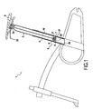
- a bicycle frame 1 on which is conventionally arranged a seat post 2 slidably mounted inside a seat tube 3.
- This seat post 2 receives at its upper end 2a a seat 4.
- a locking device 5 arranged between the seat post 2 and the seat tube 3, whose function is to block the sliding of the seat post 2 vis-à-vis the seat tube 3.
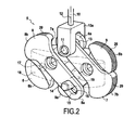
- the blocking device 5 illustrated on the figure 1 appears in more detail with regard to figures 2 and 3 . It can be seen that this locking device 5 comprises a first set of two cams 6, 7 and a second set of two cams 8, 9. The cams 6, 7 are arranged symmetrically with respect to the longitudinal axis of the seat post 2 , it is the same for the cams 8, 9. It is further noted that this locking device 5 comprises a rod 10 for actuating the cam system consisting of said cams 6, 7, 8, 9.
- the lower end 10a of the rod is configured to at least pivotally receive the proximal ends 6a, 7a of the first two cams 6, 7.
- a pivot axis 11 is disposed perpendicularly to the longitudinal axis 12 of the rod extending longitudinally in the seat post, along the longitudinal axis of said seat post, this pivot axis 11 pivotally receives said proximal ends 6a, 7a of said cams 6, 7.
- a first oblong hole 13 is arranged at the proximal end 6a of the first cam 6, this oblong hole slidably receiving the pivot axis 11, which makes it possible to slide said first proximal end 6a along the oblong hole 13 while concomitantly allowing the pivoting of the cam 6 with respect to the rod 10.
- Such an oblong hole is also arranged at the proximal end 7a of the second cam 7.
- the two proximal ends 6a, 7a cams 6, 7 are able to slide relative to the pivot axis 11 and concomitantly to pivot about the pivot axis 11.
- This design is intended to increase the pressure exerted by the cams 6, 7 on the internal face of the seat tube 3 when the seat post 2 exerts a force downwardly relative to the seat tube 3, especially when the cyclist is sitting on the saddle.
- the second cams 8, 9 are assembled together by means of a pivot axis 14 arranged parallel to the first pivot axis 11, that is to say perpendicularly to the longitudinal axis 12 of the rod 10 and the longitudinal axis of the seat post.
- pivot axis 14 is also slidably mounted in two oblong holes 15, 16 arranged at the proximal ends 8a, 9a of the two cams 8, 9.
- the two cams 8, 9 pivot together about a pivot axis 14 and slide between them along the oblong holes 15, 16.
- This design has the function of allowing the cams 8, 9 to intensify the contact pressure on the inner face of the seat tube 3 when the seat post 2 tends to be displaced outwards with respect to the seat tube 3, especially when the user lifts the bicycle by maintaining it by the saddle 4 and release the cams 6, 7 opposite.
- cam 6 and the cam 8 are each mounted and pivoted together about a pivot axis 17 relative to a fixed part 18 inside the seat post 2.
- cam 7 and the cam 9 each of which is pivotally mounted on a pivot axis 19 which is integral with the fixed part 18 inside the seat post 2.
- These two pivot axes 17 and 19 are parallel to the pivot axes 11, 14 and arranged symmetrically with respect to the longitudinal axis of the seat post 2 along which the two pivot axes 11 and 14 pass. It can be seen that the cam 6 and the cam 8 are arranged symmetrically with respect to a transverse axis passing through by the pivot axes 17, 19. It is the same for the cams 7 and 9.
- the distal ends 6b, 7b, 8b, 9b of the four cams 6, 7, 8, 9 are configured to come into contact with the inner face of the seat tube 3.
- the locking device is preferably arranged inside the seatpost 2.
- the seatpost comprises lights 20, 21, which appear in more detail on the figure 4 illustrating an alternative design of the locking device 22, these lights allowing the passage of the distal ends 6b, 7b, 8b, 9b of the four cams 6, 7, 8, 9, so as to allow them to come into contact on the inner face of the seat tube 3.
- these distal ends 6b, 7b, 8b, 9b of the four cams have a more or less rounded shape.
- a spring 38 is arranged between the pivot axis 11 and the pivot axis 14, this spring 38 extending along the longitudinal axis of the rod 10 and the seat post 2.
- This spring 38 is mounted in extension.
- This spring 38 has the function of pressing the cams 6, 7, 8, 9 against the tube 3 after loosening of the rod 10.
- the figure 4 illustrates a variant of the design of the locking device.
- the locking device 22 comprises four cams 23, 24, 25, 26 which are mounted in a cross.
- the two cams 23, 26 are implemented by means of one and the same piece 27 having a hysteresis shape; similarly, the two cams 24, 25 are implemented by means of a single piece 28 having a hysteresis shape which is symmetrical with respect to the first piece 27 along the longitudinal axis of the seat post .
- This first piece 27 and this second piece 28 are mounted pivotably about a pivot axis 29 disposed perpendicularly to the longitudinal axis of the seat post 2 and passing through this longitudinal axis, said pivot axis being fixed relative to the stem of saddle 2.
- cam 28 and the cam 26 are arranged symmetrically with respect to the pivot axis 29 or asymmetrically with respect to the longitudinal axis of the seat post 2.
- cam 25 and the cam 24 are arranged symmetrically with respect to this pivot axis 29 or asymmetrically with respect to the longitudinal axis of the seat post 2.
- the distal ends 23a, 24a, 25a, 26a have a teardrop shape which is configured to increase the pressure exerted on the inner face of the seat tube 3 when attempting to move the seat post 2 relative to to the seat tube 3 in one direction or the other along the longitudinal axis of the seat post 2.
- the distal ends 23a, 24a of the two cams 23, 24, by their droplet shape increase the pressure on the inner face of the seat tube 3 when one tends to move the seat post 2 inside the seat tube 3.
- the distal ends 25a, 26a of the two cams 25, 26, of by their droplet shape allow to accentuate the pressure exerted on the inner face of the seat tube 3 when one tends to move the seat post 2 towards the outside of the seat tube 3.
- first piece 28 constituting the two cams 23, 26 is actuated by means of a first rod 30, while the second piece 27 constituting the two cams 25, 24 is actuated by means of a second rod 31 which extends longitudinally inside the seat post 2.
- the contact surface of the cams 6, 7, 8, 9 have notches 50 for example implemented by means of a knurling, these notches 50 for increasing the adhesion of the distal ends 6b, 7b, 8b, 9b cams 6, 7, 8, 9 in contact on the inner face of the seat tube 3.
- Such notches 50 may also be envisaged on the cams 23, 24, 25, 26 according to the second design mode of the locking device 22 illustrated in figure 4 .
- the rod 10 extends longitudinally inside the seat post 2 to the level of its upper end 2a at which said rod 10 opens.
- This rod is configured to be actuated by means of a handle 32, illustrated in FIG. figure 1 .
- a similar design can be envisaged with the two rods 30, 31 illustrated on the figure 4 .
- This handle 32 allows at least to move the rod 10 in a position in which it actuates the two cams 6, 7 and, through the spring 38, the two cams 8, 9, to release these four cams 6, 7, 8, 9 of the inner face of the seat tube 3 and thus allow the sliding of the seat post 2 with respect to the seat tube 3.
- the locking device further comprises a system for repositioning the cams bearing against the inner face of the seat tube 3 so as to ensure the locking of the seat post 2 relative to the seat tube 3.
- This repositioning system can be implemented according to various design variants, according to said blocking device.
- a return spring (not shown in the figures) preferably provided between the seat post 2 and the handling handle 32 is provided, this return spring for actuating said handle 32 which acts on the rod 10 and allows to reposition the cams 6, 7, 8, 9 bearing against the inner face of the seat tube 3.
- Such a return spring can also be implemented between the handle and the upper end 2a of the rod of saddle 2, with the locking device 22 illustrated in FIG. figure 4 .
- a return spring (not shown in the figures) is arranged between the cams 23, 24, 25, 26 and the pivot axis 29 which is integral with the seat post 2.
- This return spring is particularly of the spring type spiral and allows to exert a force on the cams so as to press against the inner face of the seat tube 3 of the bicycle frame.
- the seat post and the seat tube comprise a cross section which has two flats arranged vis-à-vis.
- the seat post 2 comprises two flats 33, 34 and the seat tube 3 comprises two flats 35, 36.
- the cams for example those 6, 7, 8, 9 of the seat blocking 5 illustrated in figure 2 , are configured to come into contact in said flats 35, 36 of the seat tube 3, as schematized on the figure 5 . This makes it possible to increase the contact area between the cams and the flats 35, 36.
- the locking device 5, 22 is integrated inside the seat post 2.
- the locking device 5, 22 is integrated inside the seat post 2.
Landscapes
- Engineering & Computer Science (AREA)
- Mechanical Engineering (AREA)
- General Engineering & Computer Science (AREA)
- Mutual Connection Of Rods And Tubes (AREA)
- Motorcycle And Bicycle Frame (AREA)
- Quick-Acting Or Multi-Walled Pipe Joints (AREA)
Claims (15)
- Blockiervorrichtung (5, 22) zwischen einem ersten Rohr (2) und einem zweiten Rohr (3), die dazu ausgelegt sind, das Verschieben des ersten Rohrs (2) in dem zweiten Rohr (3) zu ermöglichen, wobei die Blockiervorrichtung wenigstens eine Stange (10, 30, 31) umfasst, die dazu ausgelegt ist, sich innerhalb des ersten Rohrs (2) zu bewegen und von außerhalb des ersten Rohrs in zwei Positionen gestellt zu werden, wobei die Blockiervorrichtung (5, 22) ein Nockensystem umfasst, das wenigstens zwei Nocken (6, 7, 8, 9, 23, 24, 25, 26) enthält, die an dem ersten Rohr um wenigstens eine Schwenkachse (17, 19, 29), welche zu einer Längsachse (12, 37) des ersten Rohrs (2) senkrecht verläuft, drehgelenkig angebracht sind und dazu ausgelegt sind, entweder in eine erste Position, in der die Nocken außer Kontakt mit dem zweiten Rohr sind und das Verschieben des ersten Rohrs innerhalb des zweiten Rohrs zulassen, oder in eine zweite Position zu schwenken, in der ein jeder der Nocken einen Druck auf die Innenseite des zweiten Rohrs ausübt und das Verschieben des ersten Rohrs innerhalb des zweiten Rohrs blockiert, wobei die Stange mit dem Nockensystem verbunden und dazu ausgelegt ist, wenigstens die Nocken in ihre erste Position zu bewegen, wenn sich die Stange in einer Entriegelungsposition befindet, wobei ein System zum erneuten Positionieren dazu ausgelegt ist, die Nocken in ihre zweite Position zurückzubringen, wobei die Blockiervorrichtung (5, 22) dadurch gekennzeichnet ist, dass das Nockensystem dazu ausgelegt ist, den Kontaktdruck der Nocken (6, 7, 8, 9, 23, 24, 25, 26) auf die Innenseite des zweiten Rohrs bei einer Erhöhung einer auf das erste Rohr ausgeübten Kraft zur Bewegung des ersten Rohrs sowohl zum Inneren des zweiten Rohrs als auch zur Außenseite des zweiten Rohrs zu verstärken.
- Blockiervorrichtung (22) zwischen einem ersten Rohr (2) und einem zweiten Rohr (3) nach Anspruch 1, die wenigstens eine Stange (30, 31) und vier Nocken (23, 24, 25, 26), welche symmetrisch und asymmetrisch in Bezug auf die Längsachse (12) des ersten Rohrs untereinander kreuzweise angebracht sind, umfasst, wobei die Nocken ferner um die Schwenkachse (29), die durch die Längsachse des ersten Rohrs verläuft und an dem ersten Rohr befestigt ist, schwenkbar angebracht sind.
- Blockiervorrichtung (5, 22) zwischen einem ersten Rohr (2) und einem zweiten Rohr (3) nach Anspruch 1 oder 2, wobei die Stange (10, 30, 31) sich innerhalb des ersten Rohrs (2) in Längsrichtung bewegt und an einem außerhalb des zweiten Rohrs angeordneten distalen Ende (2a) des ersten Rohrs ausmündet.
- Blockiervorrichtung (22) zwischen einem ersten Rohr (2) und einem zweiten Rohr (3) nach Anspruch 2, wobei eine Rückstellfeder zwischen den Nocken (23, 24, 25, 26) und der Schwenkachse (29), die mit dem ersten Rohr fest verbunden ist, angeordnet ist, wobei die Rückstellfeder dazu ausgelegt ist, eine Kraft auf die Nocken auszuüben, um die Nocken gegen die Innenseite des zweiten Rohrs zu drücken.
- Blockiervorrichtung (5) zwischen einem ersten Rohr (2) und einem zweiten Rohr (3) nach Anspruch 1, wobei das Nockensystem zwei erste Nocken (6, 7) umfasst, die um eine erste Schwenkachse (11), welche zu der Längsachse (12) des ersten Rohrs senkrecht verläuft und an der Stange (10) befestigt ist, schwenkbar untereinander angebracht sind, wobei die beiden ersten Nocken um eine zweite (17) bzw. eine dritte (19) Schwenkachse, die zu der Längsachse des ersten Rohrs senkrecht verlaufen und in Bezug auf die Längsachse symmetrisch untereinander angeordnet sind, schwenkbar angebracht sind.
- Blockiervorrichtung (5) zwischen einem ersten Rohr (2) und einem zweiten Rohr (3) nach Anspruch 5, wobei das Nockensystem zwei zweite Nocken (8, 9) umfasst, die um eine vierte Schwenkachse (14), welche zu der Längsachse (12) des ersten Rohrs senkrecht verläuft, schwenkbar untereinander angebracht sind, wobei die beiden zweiten Nocken um die zweite (17) bzw. die dritte (19) Schwenkachse schwenkbar angebracht sind, wobei die beiden zweiten Nocken zu den beiden ersten Nocken (6, 7) in Bezug auf eine Symmetrieachse, welche durch die zweite und die dritte Schwenkachse verläuft, symmetrisch angeordnet sind, wobei eine Rückstellfeder (38) zwischen der ersten Schwenkachse (11) und der vierten Schwenkachse angeordnet ist.
- Blockiervorrichtung (5) zwischen einem ersten Rohr (2) und einem zweiten Rohr (3) nach Anspruch 5 oder 6, wobei die beiden ersten Nocken (6, 7) jeweils ein Langloch (13) umfassen, das dazu ausgelegt ist, die erste Schwenkachse (11) verschieblich aufzunehmen.
- Blockiervorrichtung (5) zwischen einem ersten Rohr (2) und einem zweiten Rohr (3) nach Anspruch 6, wobei die beiden zweiten Nocken (8, 9) jeweils ein Langloch (15, 16) umfassen, das dazu ausgelegt ist, die vierte Schwenkachse (14) verschieblich aufzunehmen.
- Blockiervorrichtung (5, 22) zwischen einem ersten Rohr (2) und einem zweiten Rohr (3) nach einem der Ansprüche 1 bis 8, die einen an der Stange (10, 30, 31) befestigten Bedienungsgriff (32) umfasst, wobei der Bedienungsgriff dazu ausgelegt ist, wenigstens die Stange in ihre Entriegelungsposition zu bewegen.
- Blockiervorrichtung (5, 22) zwischen einem ersten Rohr (2) und einem zweiten Rohr (3) nach Anspruch 9, wobei eine Rückstellfeder zwischen dem ersten Rohr und dem Bedienungsgriff (32) angeordnet ist, wobei die Rückstellfeder dazu ausgelegt ist, einen Schub auf die Stange (10, 30, 31) auszuüben und die Nocken (6, 7, 8, 9, 23, 24, 25, 26) in ihre zweite Position zurückzubringen.
- Blockiervorrichtung (5, 22) zwischen einem ersten Rohr (2) und einem zweiten Rohr (3) nach einem der Ansprüche 1 bis 10, wobei die wenigstens zwei Nocken (6, 7, 8, 9, 23, 24, 25, 26) innerhalb des ersten Rohrs angeordnet sind, wobei das erste Rohr wenigstens zwei Öffnungen (20, 21) umfasst, die dazu ausgelegt sind, den Durchgang der Nocken zu ermöglichen, um sie in ihrer zweiten Position, in Kontakt an der Innenseite des zweiten Rohrs anzuordnen.
- Blockiervorrichtung (5, 22) zwischen einem ersten Rohr (2) und einem zweiten Rohr (3) nach einem der Ansprüche 1 bis 11, wobei die Nocken (6, 7, 8, 9, 23, 24, 25, 26) jeweils wenigstens eine Fläche zum Kontakt an der Innenseite des zweiten Rohrs umfassen, wobei die Kontaktfläche Rasten (50) umfasst, die dazu ausgelegt sind, an der Innenseite des zweiten Rohrs anzugreifen.
- Fahrrad (1), umfassend insbesondere einen Rahmen, der ein Sattelrohr (3), einen Sattel (4) sowie eine Sattelstütze (2), welche den Sattel nach unten fortsetzt, umfasst, wobei die Sattelstütze in dem Sattelrohr verschieblich angebracht ist, wobei das Fahrrad ferner eine Blockiervorrichtung (5, 22), welche Gegenstand von einem der Ansprüche 1 bis 12 ist, umfasst, wobei die Sattelstütze das erste Rohr bildet und das Sattelrohr das zweite Rohr bildet.
- Fahrrad (1) nach Anspruch 13, wobei ein Griff zur Bedienung (32) der Stange unter dem Sattel (4) angeordnet ist.
- Fahrrad (1) nach Anspruch 14, wobei die Sattelstütze (2) und das Sattelrohr (3) jeweils einen Querschnitt mit zwei einander gegenüberliegenden Abflachungen (33, 34, 35, 36) aufweisen, wobei die Nocken (6, 7, 8, 9, 23, 24, 25, 26) sich an den Abflachungen (35, 36) des Sattelrohrs abstützen.
Applications Claiming Priority (2)
| Application Number | Priority Date | Filing Date | Title |
|---|---|---|---|
| FR1061401A FR2969981B1 (fr) | 2010-12-31 | 2010-12-31 | Dispositif de blocage entre deux tubes montes a coulissement |
| PCT/FR2011/050436 WO2012089941A1 (fr) | 2010-12-31 | 2011-03-02 | Dispositif de blocage entre deux tubes montes a coulissement |
Publications (2)
| Publication Number | Publication Date |
|---|---|
| EP2659149A1 EP2659149A1 (de) | 2013-11-06 |
| EP2659149B1 true EP2659149B1 (de) | 2015-01-14 |
Family
ID=43971296
Family Applications (1)
| Application Number | Title | Priority Date | Filing Date |
|---|---|---|---|
| EP11712954.4A Active EP2659149B1 (de) | 2010-12-31 | 2011-03-02 | Vorrichtung zum gegenseitigen verriegeln zweier gleitbare montierbarer rohre |
Country Status (8)
| Country | Link |
|---|---|
| US (1) | US9010791B2 (de) |
| EP (1) | EP2659149B1 (de) |
| CN (1) | CN103392073B (de) |
| BR (1) | BR112013016803A2 (de) |
| ES (1) | ES2533565T3 (de) |
| FR (1) | FR2969981B1 (de) |
| TW (1) | TWI457258B (de) |
| WO (1) | WO2012089941A1 (de) |
Families Citing this family (10)
| Publication number | Priority date | Publication date | Assignee | Title |
|---|---|---|---|---|
| GB2496671B (en) * | 2011-11-21 | 2013-10-30 | Poss Ltd | Height adjustment mechanism for a cycle |
| CN203888933U (zh) * | 2013-04-12 | 2014-10-22 | 巨大机械工业股份有限公司 | 自行车座杆调整结构 |
| FR3011812B1 (fr) * | 2013-10-10 | 2017-03-10 | Look Cycle Int | Dispositif de fixation d'un element de cycle detachable sur un cycle, et utilisation d'un tel dispositif |
| DE102015205355A1 (de) * | 2015-03-24 | 2016-09-29 | Aktiebolaget Skf | Hubsäule |
| US9688331B1 (en) * | 2016-01-29 | 2017-06-27 | Shimano Inc. | Bicycle adjustable seat post assembly |
| US10472012B2 (en) * | 2016-02-05 | 2019-11-12 | Shimano Inc. | Bicycle seatpost assembly |
| TWI570012B (zh) | 2016-02-24 | 2017-02-11 | 台灣穗高工業股份有限公司 | Bicycle seat height adjustment mechanism |
| WO2018132741A1 (en) * | 2017-01-14 | 2018-07-19 | Icon Health & Fitness, Inc. | Exercise cycle |
| CN109780012B (zh) * | 2019-02-25 | 2023-11-14 | 橙象医疗科技(广州)有限公司 | 一种轴向双向锁定装置及悬吊康复设备 |
| WO2024123542A1 (en) * | 2022-12-08 | 2024-06-13 | Defense Technology, Llc | Locking assembly for telescoping baton |
Family Cites Families (14)
| Publication number | Priority date | Publication date | Assignee | Title |
|---|---|---|---|---|
| DE9013266U1 (de) * | 1990-09-19 | 1990-11-22 | Hans Lutz Rennräder GmbH & Co. KG, 7902 Blaubeuren | Zweirad mit einem höhenverstellbaren Sattel |
| JP3432397B2 (ja) * | 1996-12-20 | 2003-08-04 | 松下電器産業株式会社 | 盗難防止装置付き自転車 |
| US6142699A (en) * | 1998-04-21 | 2000-11-07 | Asia Link Co., Ltd. | Telescopic rod |
| TW522954U (en) | 2001-08-27 | 2003-03-01 | Kuen-Jung Liou | Bicycle capable of adjusting the height of seat during traveling |
| US7025522B2 (en) * | 2003-04-18 | 2006-04-11 | Wayne Sicz | Adjustable bicycle seat post assembly |
| US20060193679A1 (en) * | 2005-02-25 | 2006-08-31 | Thomas Lin | Retractable tube assembly |
| US7708251B2 (en) * | 2006-03-17 | 2010-05-04 | Nautilus, Inc. | Mechanism and method for adjusting seat height for exercise equipment |
| GB0717001D0 (en) * | 2007-08-31 | 2007-10-10 | Karbon Kinetics Ltd | Bicycle seat post with internal height adjustment mechanism |
| IT1390884B1 (it) * | 2008-09-29 | 2011-10-19 | Technogym Spa | Dispositivo di regolazione |
| TWM355888U (en) | 2008-12-30 | 2009-05-01 | Ritchey Designs Inc | Height-adjustable type bicycle seat post structure |
| CN201350944Y (zh) | 2009-01-21 | 2009-11-25 | 爱菲斯国际有限公司 | 一种可调整式自行车座管及安装有该座管的自行车 |
| DE102009009645A1 (de) * | 2009-02-19 | 2010-08-26 | Jochen Klieber | Längenverstellbare Sattelstütze |
| US8317261B2 (en) * | 2010-11-03 | 2012-11-27 | Austin A. Walsh | Bicycle seat height adjusting assembly |
| US8702339B2 (en) * | 2011-06-24 | 2014-04-22 | Manic Nomad, LLC | Clamp |
-
2010
- 2010-12-31 FR FR1061401A patent/FR2969981B1/fr active Active
-
2011
- 2011-03-02 ES ES11712954.4T patent/ES2533565T3/es active Active
- 2011-03-02 US US13/992,764 patent/US9010791B2/en active Active
- 2011-03-02 CN CN201180063609.8A patent/CN103392073B/zh active Active
- 2011-03-02 BR BR112013016803A patent/BR112013016803A2/pt not_active IP Right Cessation
- 2011-03-02 WO PCT/FR2011/050436 patent/WO2012089941A1/fr not_active Ceased
- 2011-03-02 EP EP11712954.4A patent/EP2659149B1/de active Active
- 2011-12-22 TW TW100148094A patent/TWI457258B/zh active
Also Published As
| Publication number | Publication date |
|---|---|
| US20130328285A1 (en) | 2013-12-12 |
| FR2969981B1 (fr) | 2014-10-10 |
| ES2533565T3 (es) | 2015-04-13 |
| EP2659149A1 (de) | 2013-11-06 |
| US9010791B2 (en) | 2015-04-21 |
| CN103392073A (zh) | 2013-11-13 |
| CN103392073B (zh) | 2015-05-27 |
| TWI457258B (zh) | 2014-10-21 |
| TW201231337A (en) | 2012-08-01 |
| BR112013016803A2 (pt) | 2016-09-27 |
| FR2969981A1 (fr) | 2012-07-06 |
| WO2012089941A1 (fr) | 2012-07-05 |
Similar Documents
| Publication | Publication Date | Title |
|---|---|---|
| WO2012089941A1 (fr) | Dispositif de blocage entre deux tubes montes a coulissement | |
| FR2857400A1 (fr) | Verrou destine a relier deux panneaux d'une structure d'aeroplane | |
| FR2934802A1 (fr) | Pistolet a attaches | |
| EP0146454A2 (de) | Vorrichtung zum Festklemmen eines Schuhes an einem Fahrradpedal | |
| CH649201A5 (fr) | Chaussure de ski et fixation reliee a un ski destinee a cooperer avec cette chaussure. | |
| CA2841680C (fr) | Dispositif de prehension amovible d'un recipient culinaire muni de moyens antiretour de deux bras | |
| EP1626893B1 (de) | Vorrichtung mit einem schnellklemmmechanismus zur befestigung eines fahrradrades an einem rahmen mit einem überhang | |
| EP1349451B1 (de) | Unterwasserharpune vom armbrusttyp mit spannvorrichtung | |
| FR2815320A3 (fr) | Trottinette a mecanisme amortisseur | |
| EP3345660B1 (de) | Anschlag für fixierungsvorrichtung eines schuhs | |
| FR2807384A1 (fr) | Dispositif de fixation automatique et pedale de cycliste pourvue d'un tel dispositif | |
| EP0380597A1 (de) | Bremseinrichtung für rollschuhe bzw. rollbretter | |
| EP0040574A1 (de) | Betätigungsvorrichtung für die Handbremse | |
| FR2684962A1 (fr) | Boitier a ouverture controlee. | |
| EP2417377A1 (de) | Linearvorrichtung mit gesteuerten reibung, in der eine druckkraft senkrecht zur bewegung angelegt wird | |
| FR2656858A1 (fr) | Structure unitaire deplacable de calage ou de soutien d'un vehicule routier par ses roues. | |
| FR2966490A1 (fr) | Verrou a crochet muni d'un ressort perfectionne | |
| EP0592341B1 (de) | Verbesserung an Türgriffen mit einer plattenförmigen Handhabe | |
| FR2944538A1 (fr) | Attache volante de support et de fixation de structure sur une paroi, munie d'un tampon d'appui axial. | |
| FR2944540A1 (fr) | Attache volante securisee de support et de fixation de structure sur une paroi. | |
| FR2659840A1 (fr) | Support de suspension d'objets notamment a une cimaise. | |
| FR2627958A1 (fr) | Casque de protection sans jugulaire et systeme d'amortissement des mouvements du dispositif d'assujettissement des casques sans jugulaire | |
| FR2896669A1 (fr) | Bagage a main du type remorquable equipe d'une canne amortie | |
| EP1445169A1 (de) | Gleitdrehlager einer verstellbaren Lenksäule eines Kraftfahrzeuges | |
| EP1270980B1 (de) | Scheibenbremse, insbesondere für Industriegebrauch |
Legal Events
| Date | Code | Title | Description |
|---|---|---|---|
| PUAI | Public reference made under article 153(3) epc to a published international application that has entered the european phase |
Free format text: ORIGINAL CODE: 0009012 |
|
| 17P | Request for examination filed |
Effective date: 20130627 |
|
| AK | Designated contracting states |
Kind code of ref document: A1 Designated state(s): AL AT BE BG CH CY CZ DE DK EE ES FI FR GB GR HR HU IE IS IT LI LT LU LV MC MK MT NL NO PL PT RO RS SE SI SK SM TR |
|
| RIN1 | Information on inventor provided before grant (corrected) |
Inventor name: BASSETTI, PIERRE, LOUIS Inventor name: FROHLICHER, FABIEN Inventor name: MARAIS, TONY |
|
| DAX | Request for extension of the european patent (deleted) | ||
| RIC1 | Information provided on ipc code assigned before grant |
Ipc: F16B 2/18 20060101AFI20140710BHEP Ipc: B62K 19/36 20060101ALI20140710BHEP Ipc: F16B 2/04 20060101ALI20140710BHEP Ipc: B62J 1/08 20060101ALI20140710BHEP Ipc: F16B 7/14 20060101ALI20140710BHEP |
|
| RIN1 | Information on inventor provided before grant (corrected) |
Inventor name: FROHLICHER, FABIEN Inventor name: MARAIS, TONY Inventor name: BASSETTI, PIERRE, LOUIS |
|
| GRAP | Despatch of communication of intention to grant a patent |
Free format text: ORIGINAL CODE: EPIDOSNIGR1 |
|
| INTG | Intention to grant announced |
Effective date: 20140923 |
|
| RAP1 | Party data changed (applicant data changed or rights of an application transferred) |
Owner name: DECATHLON |
|
| GRAS | Grant fee paid |
Free format text: ORIGINAL CODE: EPIDOSNIGR3 |
|
| GRAA | (expected) grant |
Free format text: ORIGINAL CODE: 0009210 |
|
| AK | Designated contracting states |
Kind code of ref document: B1 Designated state(s): AL AT BE BG CH CY CZ DE DK EE ES FI FR GB GR HR HU IE IS IT LI LT LU LV MC MK MT NL NO PL PT RO RS SE SI SK SM TR |
|
| REG | Reference to a national code |
Ref country code: GB Ref legal event code: FG4D Free format text: NOT ENGLISH |
|
| REG | Reference to a national code |
Ref country code: CH Ref legal event code: EP |
|
| REG | Reference to a national code |
Ref country code: IE Ref legal event code: FG4D Free format text: LANGUAGE OF EP DOCUMENT: FRENCH |
|
| REG | Reference to a national code |
Ref country code: AT Ref legal event code: REF Ref document number: 707219 Country of ref document: AT Kind code of ref document: T Effective date: 20150215 |
|
| REG | Reference to a national code |
Ref country code: DE Ref legal event code: R096 Ref document number: 602011013127 Country of ref document: DE Effective date: 20150305 |
|
| REG | Reference to a national code |
Ref country code: ES Ref legal event code: FG2A Ref document number: 2533565 Country of ref document: ES Kind code of ref document: T3 Effective date: 20150413 |
|
| REG | Reference to a national code |
Ref country code: NL Ref legal event code: VDEP Effective date: 20150114 |
|
| REG | Reference to a national code |
Ref country code: AT Ref legal event code: MK05 Ref document number: 707219 Country of ref document: AT Kind code of ref document: T Effective date: 20150114 |
|
| REG | Reference to a national code |
Ref country code: LT Ref legal event code: MG4D |
|
| PG25 | Lapsed in a contracting state [announced via postgrant information from national office to epo] |
Ref country code: HR Free format text: LAPSE BECAUSE OF FAILURE TO SUBMIT A TRANSLATION OF THE DESCRIPTION OR TO PAY THE FEE WITHIN THE PRESCRIBED TIME-LIMIT Effective date: 20150114 Ref country code: FI Free format text: LAPSE BECAUSE OF FAILURE TO SUBMIT A TRANSLATION OF THE DESCRIPTION OR TO PAY THE FEE WITHIN THE PRESCRIBED TIME-LIMIT Effective date: 20150114 Ref country code: SE Free format text: LAPSE BECAUSE OF FAILURE TO SUBMIT A TRANSLATION OF THE DESCRIPTION OR TO PAY THE FEE WITHIN THE PRESCRIBED TIME-LIMIT Effective date: 20150114 Ref country code: NO Free format text: LAPSE BECAUSE OF FAILURE TO SUBMIT A TRANSLATION OF THE DESCRIPTION OR TO PAY THE FEE WITHIN THE PRESCRIBED TIME-LIMIT Effective date: 20150414 Ref country code: LT Free format text: LAPSE BECAUSE OF FAILURE TO SUBMIT A TRANSLATION OF THE DESCRIPTION OR TO PAY THE FEE WITHIN THE PRESCRIBED TIME-LIMIT Effective date: 20150114 Ref country code: BG Free format text: LAPSE BECAUSE OF FAILURE TO SUBMIT A TRANSLATION OF THE DESCRIPTION OR TO PAY THE FEE WITHIN THE PRESCRIBED TIME-LIMIT Effective date: 20150414 |
|
| PG25 | Lapsed in a contracting state [announced via postgrant information from national office to epo] |
Ref country code: NL Free format text: LAPSE BECAUSE OF FAILURE TO SUBMIT A TRANSLATION OF THE DESCRIPTION OR TO PAY THE FEE WITHIN THE PRESCRIBED TIME-LIMIT Effective date: 20150114 Ref country code: IS Free format text: LAPSE BECAUSE OF FAILURE TO SUBMIT A TRANSLATION OF THE DESCRIPTION OR TO PAY THE FEE WITHIN THE PRESCRIBED TIME-LIMIT Effective date: 20150514 Ref country code: LV Free format text: LAPSE BECAUSE OF FAILURE TO SUBMIT A TRANSLATION OF THE DESCRIPTION OR TO PAY THE FEE WITHIN THE PRESCRIBED TIME-LIMIT Effective date: 20150114 Ref country code: PL Free format text: LAPSE BECAUSE OF FAILURE TO SUBMIT A TRANSLATION OF THE DESCRIPTION OR TO PAY THE FEE WITHIN THE PRESCRIBED TIME-LIMIT Effective date: 20150114 Ref country code: AT Free format text: LAPSE BECAUSE OF FAILURE TO SUBMIT A TRANSLATION OF THE DESCRIPTION OR TO PAY THE FEE WITHIN THE PRESCRIBED TIME-LIMIT Effective date: 20150114 Ref country code: GR Free format text: LAPSE BECAUSE OF FAILURE TO SUBMIT A TRANSLATION OF THE DESCRIPTION OR TO PAY THE FEE WITHIN THE PRESCRIBED TIME-LIMIT Effective date: 20150415 Ref country code: RS Free format text: LAPSE BECAUSE OF FAILURE TO SUBMIT A TRANSLATION OF THE DESCRIPTION OR TO PAY THE FEE WITHIN THE PRESCRIBED TIME-LIMIT Effective date: 20150114 |
|
| REG | Reference to a national code |
Ref country code: DE Ref legal event code: R097 Ref document number: 602011013127 Country of ref document: DE |
|
| PG25 | Lapsed in a contracting state [announced via postgrant information from national office to epo] |
Ref country code: LU Free format text: LAPSE BECAUSE OF FAILURE TO SUBMIT A TRANSLATION OF THE DESCRIPTION OR TO PAY THE FEE WITHIN THE PRESCRIBED TIME-LIMIT Effective date: 20150302 Ref country code: EE Free format text: LAPSE BECAUSE OF FAILURE TO SUBMIT A TRANSLATION OF THE DESCRIPTION OR TO PAY THE FEE WITHIN THE PRESCRIBED TIME-LIMIT Effective date: 20150114 Ref country code: MC Free format text: LAPSE BECAUSE OF FAILURE TO SUBMIT A TRANSLATION OF THE DESCRIPTION OR TO PAY THE FEE WITHIN THE PRESCRIBED TIME-LIMIT Effective date: 20150114 Ref country code: SK Free format text: LAPSE BECAUSE OF FAILURE TO SUBMIT A TRANSLATION OF THE DESCRIPTION OR TO PAY THE FEE WITHIN THE PRESCRIBED TIME-LIMIT Effective date: 20150114 Ref country code: CZ Free format text: LAPSE BECAUSE OF FAILURE TO SUBMIT A TRANSLATION OF THE DESCRIPTION OR TO PAY THE FEE WITHIN THE PRESCRIBED TIME-LIMIT Effective date: 20150114 Ref country code: DK Free format text: LAPSE BECAUSE OF FAILURE TO SUBMIT A TRANSLATION OF THE DESCRIPTION OR TO PAY THE FEE WITHIN THE PRESCRIBED TIME-LIMIT Effective date: 20150114 Ref country code: RO Free format text: LAPSE BECAUSE OF FAILURE TO SUBMIT A TRANSLATION OF THE DESCRIPTION OR TO PAY THE FEE WITHIN THE PRESCRIBED TIME-LIMIT Effective date: 20150114 |
|
| REG | Reference to a national code |
Ref country code: CH Ref legal event code: PL |
|
| PLBE | No opposition filed within time limit |
Free format text: ORIGINAL CODE: 0009261 |
|
| STAA | Information on the status of an ep patent application or granted ep patent |
Free format text: STATUS: NO OPPOSITION FILED WITHIN TIME LIMIT |
|
| 26N | No opposition filed |
Effective date: 20151015 |
|
| GBPC | Gb: european patent ceased through non-payment of renewal fee |
Effective date: 20150414 |
|
| REG | Reference to a national code |
Ref country code: IE Ref legal event code: MM4A |
|
| PG25 | Lapsed in a contracting state [announced via postgrant information from national office to epo] |
Ref country code: CH Free format text: LAPSE BECAUSE OF NON-PAYMENT OF DUE FEES Effective date: 20150331 Ref country code: LI Free format text: LAPSE BECAUSE OF NON-PAYMENT OF DUE FEES Effective date: 20150331 Ref country code: IE Free format text: LAPSE BECAUSE OF NON-PAYMENT OF DUE FEES Effective date: 20150302 Ref country code: GB Free format text: LAPSE BECAUSE OF NON-PAYMENT OF DUE FEES Effective date: 20150414 |
|
| REG | Reference to a national code |
Ref country code: FR Ref legal event code: PLFP Year of fee payment: 6 |
|
| PG25 | Lapsed in a contracting state [announced via postgrant information from national office to epo] |
Ref country code: SI Free format text: LAPSE BECAUSE OF FAILURE TO SUBMIT A TRANSLATION OF THE DESCRIPTION OR TO PAY THE FEE WITHIN THE PRESCRIBED TIME-LIMIT Effective date: 20150114 |
|
| PG25 | Lapsed in a contracting state [announced via postgrant information from national office to epo] |
Ref country code: MT Free format text: LAPSE BECAUSE OF FAILURE TO SUBMIT A TRANSLATION OF THE DESCRIPTION OR TO PAY THE FEE WITHIN THE PRESCRIBED TIME-LIMIT Effective date: 20150114 |
|
| REG | Reference to a national code |
Ref country code: FR Ref legal event code: PLFP Year of fee payment: 7 |
|
| PG25 | Lapsed in a contracting state [announced via postgrant information from national office to epo] |
Ref country code: SM Free format text: LAPSE BECAUSE OF FAILURE TO SUBMIT A TRANSLATION OF THE DESCRIPTION OR TO PAY THE FEE WITHIN THE PRESCRIBED TIME-LIMIT Effective date: 20150114 Ref country code: HU Free format text: LAPSE BECAUSE OF FAILURE TO SUBMIT A TRANSLATION OF THE DESCRIPTION OR TO PAY THE FEE WITHIN THE PRESCRIBED TIME-LIMIT; INVALID AB INITIO Effective date: 20110302 |
|
| PG25 | Lapsed in a contracting state [announced via postgrant information from national office to epo] |
Ref country code: CY Free format text: LAPSE BECAUSE OF FAILURE TO SUBMIT A TRANSLATION OF THE DESCRIPTION OR TO PAY THE FEE WITHIN THE PRESCRIBED TIME-LIMIT Effective date: 20150114 |
|
| PG25 | Lapsed in a contracting state [announced via postgrant information from national office to epo] |
Ref country code: BE Free format text: LAPSE BECAUSE OF NON-PAYMENT OF DUE FEES Effective date: 20150331 Ref country code: PT Free format text: LAPSE BECAUSE OF FAILURE TO SUBMIT A TRANSLATION OF THE DESCRIPTION OR TO PAY THE FEE WITHIN THE PRESCRIBED TIME-LIMIT Effective date: 20150514 |
|
| PG25 | Lapsed in a contracting state [announced via postgrant information from national office to epo] |
Ref country code: TR Free format text: LAPSE BECAUSE OF FAILURE TO SUBMIT A TRANSLATION OF THE DESCRIPTION OR TO PAY THE FEE WITHIN THE PRESCRIBED TIME-LIMIT Effective date: 20150114 |
|
| REG | Reference to a national code |
Ref country code: FR Ref legal event code: PLFP Year of fee payment: 8 |
|
| PG25 | Lapsed in a contracting state [announced via postgrant information from national office to epo] |
Ref country code: MK Free format text: LAPSE BECAUSE OF FAILURE TO SUBMIT A TRANSLATION OF THE DESCRIPTION OR TO PAY THE FEE WITHIN THE PRESCRIBED TIME-LIMIT Effective date: 20150114 |
|
| PG25 | Lapsed in a contracting state [announced via postgrant information from national office to epo] |
Ref country code: AL Free format text: LAPSE BECAUSE OF FAILURE TO SUBMIT A TRANSLATION OF THE DESCRIPTION OR TO PAY THE FEE WITHIN THE PRESCRIBED TIME-LIMIT Effective date: 20150114 |
|
| REG | Reference to a national code |
Ref country code: DE Ref legal event code: R082 Ref document number: 602011013127 Country of ref document: DE Representative=s name: CBDL PATENTANWAELTE GBR, DE Ref country code: DE Ref legal event code: R082 Ref document number: 602011013127 Country of ref document: DE Representative=s name: CBDL PATENTANWAELTE EGBR, DE |
|
| P01 | Opt-out of the competence of the unified patent court (upc) registered |
Effective date: 20230605 |
|
| PGFP | Annual fee paid to national office [announced via postgrant information from national office to epo] |
Ref country code: ES Payment date: 20250410 Year of fee payment: 15 |
|
| PGFP | Annual fee paid to national office [announced via postgrant information from national office to epo] |
Ref country code: DE Payment date: 20260313 Year of fee payment: 16 |
|
| PGFP | Annual fee paid to national office [announced via postgrant information from national office to epo] |
Ref country code: IT Payment date: 20260310 Year of fee payment: 16 |
|
| PGFP | Annual fee paid to national office [announced via postgrant information from national office to epo] |
Ref country code: FR Payment date: 20260318 Year of fee payment: 16 |