EP2659201B1 - Hybrid absorption-compression chiller and a related method for providing refrigeration effect - Google Patents
Hybrid absorption-compression chiller and a related method for providing refrigeration effect Download PDFInfo
- Publication number
- EP2659201B1 EP2659201B1 EP11852445.3A EP11852445A EP2659201B1 EP 2659201 B1 EP2659201 B1 EP 2659201B1 EP 11852445 A EP11852445 A EP 11852445A EP 2659201 B1 EP2659201 B1 EP 2659201B1
- Authority
- EP
- European Patent Office
- Prior art keywords
- refrigerant
- solution
- dilute
- evaporator
- primary
- Prior art date
- Legal status (The legal status is an assumption and is not a legal conclusion. Google has not performed a legal analysis and makes no representation as to the accuracy of the status listed.)
- Active
Links
Images

Classifications
-
- F—MECHANICAL ENGINEERING; LIGHTING; HEATING; WEAPONS; BLASTING
- F25—REFRIGERATION OR COOLING; COMBINED HEATING AND REFRIGERATION SYSTEMS; HEAT PUMP SYSTEMS; MANUFACTURE OR STORAGE OF ICE; LIQUEFACTION SOLIDIFICATION OF GASES
- F25B—REFRIGERATION MACHINES, PLANTS OR SYSTEMS; COMBINED HEATING AND REFRIGERATION SYSTEMS; HEAT PUMP SYSTEMS
- F25B25/00—Machines, plants or systems, using a combination of modes of operation covered by two or more of the groups F25B1/00 - F25B23/00
- F25B25/02—Compression-sorption machines, plants, or systems
-
- F—MECHANICAL ENGINEERING; LIGHTING; HEATING; WEAPONS; BLASTING
- F25—REFRIGERATION OR COOLING; COMBINED HEATING AND REFRIGERATION SYSTEMS; HEAT PUMP SYSTEMS; MANUFACTURE OR STORAGE OF ICE; LIQUEFACTION SOLIDIFICATION OF GASES
- F25B—REFRIGERATION MACHINES, PLANTS OR SYSTEMS; COMBINED HEATING AND REFRIGERATION SYSTEMS; HEAT PUMP SYSTEMS
- F25B15/00—Sorption machines, plants or systems, operating continuously, e.g. absorption type
- F25B15/002—Sorption machines, plants or systems, operating continuously, e.g. absorption type using the endothermic solution of salt
-
- F—MECHANICAL ENGINEERING; LIGHTING; HEATING; WEAPONS; BLASTING
- F25—REFRIGERATION OR COOLING; COMBINED HEATING AND REFRIGERATION SYSTEMS; HEAT PUMP SYSTEMS; MANUFACTURE OR STORAGE OF ICE; LIQUEFACTION SOLIDIFICATION OF GASES
- F25B—REFRIGERATION MACHINES, PLANTS OR SYSTEMS; COMBINED HEATING AND REFRIGERATION SYSTEMS; HEAT PUMP SYSTEMS
- F25B35/00—Boiler-absorbers, i.e. boilers usable for absorption or adsorption
- F25B35/02—Boiler-absorbers, i.e. boilers usable for absorption or adsorption using a liquid as sorbent, e.g. brine
-
- F—MECHANICAL ENGINEERING; LIGHTING; HEATING; WEAPONS; BLASTING
- F25—REFRIGERATION OR COOLING; COMBINED HEATING AND REFRIGERATION SYSTEMS; HEAT PUMP SYSTEMS; MANUFACTURE OR STORAGE OF ICE; LIQUEFACTION SOLIDIFICATION OF GASES
- F25B—REFRIGERATION MACHINES, PLANTS OR SYSTEMS; COMBINED HEATING AND REFRIGERATION SYSTEMS; HEAT PUMP SYSTEMS
- F25B39/00—Evaporators; Condensers
- F25B39/02—Evaporators
- F25B39/026—Evaporators specially adapted for sorption type systems
-
- F—MECHANICAL ENGINEERING; LIGHTING; HEATING; WEAPONS; BLASTING
- F25—REFRIGERATION OR COOLING; COMBINED HEATING AND REFRIGERATION SYSTEMS; HEAT PUMP SYSTEMS; MANUFACTURE OR STORAGE OF ICE; LIQUEFACTION SOLIDIFICATION OF GASES
- F25B—REFRIGERATION MACHINES, PLANTS OR SYSTEMS; COMBINED HEATING AND REFRIGERATION SYSTEMS; HEAT PUMP SYSTEMS
- F25B2339/00—Details of evaporators; Details of condensers
- F25B2339/02—Details of evaporators
- F25B2339/021—Evaporators in which refrigerant is sprayed on a surface to be cooled
-
- F—MECHANICAL ENGINEERING; LIGHTING; HEATING; WEAPONS; BLASTING
- F25—REFRIGERATION OR COOLING; COMBINED HEATING AND REFRIGERATION SYSTEMS; HEAT PUMP SYSTEMS; MANUFACTURE OR STORAGE OF ICE; LIQUEFACTION SOLIDIFICATION OF GASES
- F25B—REFRIGERATION MACHINES, PLANTS OR SYSTEMS; COMBINED HEATING AND REFRIGERATION SYSTEMS; HEAT PUMP SYSTEMS
- F25B2339/00—Details of evaporators; Details of condensers
- F25B2339/04—Details of condensers
- F25B2339/047—Water-cooled condensers
-
- Y—GENERAL TAGGING OF NEW TECHNOLOGICAL DEVELOPMENTS; GENERAL TAGGING OF CROSS-SECTIONAL TECHNOLOGIES SPANNING OVER SEVERAL SECTIONS OF THE IPC; TECHNICAL SUBJECTS COVERED BY FORMER USPC CROSS-REFERENCE ART COLLECTIONS [XRACs] AND DIGESTS
- Y02—TECHNOLOGIES OR APPLICATIONS FOR MITIGATION OR ADAPTATION AGAINST CLIMATE CHANGE
- Y02A—TECHNOLOGIES FOR ADAPTATION TO CLIMATE CHANGE
- Y02A30/00—Adapting or protecting infrastructure or their operation
- Y02A30/27—Relating to heating, ventilation or air conditioning [HVAC] technologies
-
- Y—GENERAL TAGGING OF NEW TECHNOLOGICAL DEVELOPMENTS; GENERAL TAGGING OF CROSS-SECTIONAL TECHNOLOGIES SPANNING OVER SEVERAL SECTIONS OF THE IPC; TECHNICAL SUBJECTS COVERED BY FORMER USPC CROSS-REFERENCE ART COLLECTIONS [XRACs] AND DIGESTS
- Y02—TECHNOLOGIES OR APPLICATIONS FOR MITIGATION OR ADAPTATION AGAINST CLIMATE CHANGE
- Y02B—CLIMATE CHANGE MITIGATION TECHNOLOGIES RELATED TO BUILDINGS, e.g. HOUSING, HOUSE APPLIANCES OR RELATED END-USER APPLICATIONS
- Y02B30/00—Energy efficient heating, ventilation or air conditioning [HVAC]
- Y02B30/62—Absorption based systems
Definitions
- This invention relates to hybrid absorption-compression chillers for providing refrigeration and to a method for providing refrigeration effect.
- Refrigeration process are commonly used in industries to: liquefy gases like oxygen, nitrogen, propane and methane, purify compressed air of moisture, maintain a low process temperature in oil/petrochemical/chemical processes, and for tempering metal in metallurgy industry.
- the chiller apparatus commonly used to obtain refrigeration are broadly based on vapor compression or vapor absorption principle. These apparatus utilize the ability of liquids or salts to absorb vapors of a working fluid and give heating and/or cooling effect.
- the vapor absorption chiller apparatus are thermally driven, which means that heat from waste source or heat derived from solar collectors rather than mechanical energy is used to drive the cycle; whereas, the vapor compression chiller apparatus use high grade energy (electrical energy) from mechanical inputs.
- the basic difference between an absorption chiller apparatus and a compression chiller apparatus is that the compression chiller uses an electric motor for operating a compressor for raising the pressure of refrigerant vapors whereas an absorption chiller uses heat for compressing the refrigerant vapors to a high pressure.
- absorption chiller apparatus are more economical and environmental friendly since they employ low-grade waste heat, conserve electricity, and use non-ozone depleting refrigerants (water); however, compression chiller apparatus are more preferred due to their higher coefficient of performance (COP).
- absorption chillers have been combined with compression chillers to provide cooling at lowest energy costs.
- Such hybrid chiller thus devised, operates the absorption chiller during high electric peak load when the charges are high, whereas the compression chiller is operated during low electric peak load when the charges are low, thereby providing a more economical system.
- a basic refrigeration cycle for a hybrid absorption-compression chiller uses a low temperature liquid refrigerant that absorbs heat from water, air, or any medium to be cooled, and converts to a vapor phase in an evaporator section.
- the refrigerant vapors are then compressed to a high pressure, by a compressor or a generator, converted back to a liquid by rejecting heat to the external surrounding, in a condenser section, and then expanded to a low-pressure mixture of liquid and vapor, that goes back to the evaporator section and the cycle is repeated.
- Japanese patent document JPH0926226A discloses a refrigeration system that employs a two-stage compression single stage expansion refrigeration cycle and an absorption refrigeration cycle for obtaining an ultra-low temperature of about -30 degrees C.
- the system includes a heat engine, a low pressure side compressor, an intercooler, a high pressure side compressor through which a first refrigerant is passed to absorb heat.
- the refrigerant is cooled by a concentrated aqueous solution of lithium bromide and water which is diluted by water sprayed on the heat exchanger in the evaporator of the compression refrigeration cycle.
- JPH0926226A does not teach a hybrid absorption-compression chiller comprising single-stage vapor compression refrigeration and single-stage vapor absorption refrigeration cycles
- JPH092622A discloses a hybrid absorption-compression chiller and a related method for providing refrigeration effect, the hybrid absorption-compression chiller having: a vapor-compression system comprising a primary evaporator adapted to provide refrigeration by extracting heat from a medium to be cooled for vaporizing a cold condensed primary refrigerant, and a compressor in communication with said primary evaporator to receive primary refrigerant vapors, said compressor being adapted to generate high pressure primary refrigerant vapors; a vapor-absorption system provided in operative communication with said vapor-compression system for receiving the high pressure primary refrigerant vapors, said vapor-absorption system comprising a secondary e
- US patent application US20100270005 discloses a vapor absorption system for the purpose of refrigeration, wherein the chiller heat pump utilizes a double-effect vapor absorption cycle for facilitating selective heating and refrigeration purposes in an HVAC unit.
- a multiple heat exchangers are used for transferring heat with different heat sources and heat sinks.
- US Patent No. 7765823 discloses a hybrid vapor compression-absorption cooling or heating system and apparatus thereof, employing a refrigerant pair comprising at least one refrigerant and at least one ionic liquid.
- the apparatus comprises: an absorber that forms a mixture of a refrigerant and an absorbent, a generator that heats the mixture and separates the refrigerant vapors, a condenser that receives the vapors and condenses them to a liquid, a pressure reduction device to reduce the pressure of the liquid refrigerant to form a mixture of liquid and vapor refrigerant, an evaporator that receives the mixture to evaporate the remaining liquid and provide a first and a second portion of refrigerant vapors, a compressor that receives the first portion of the vapors increases the pressure and passes to the condenser, a conduit that passes the second portion of the vapors to the absorber which comprises one or more ionic liquids.
- US Patent No. 7624588 discloses a hybrid absorption-compression chiller which uses high temperature steam and medium temperature water generated in industrial processes as a heat source.
- the chiller comprises: a high temperature generator that uses the high temperature steam so as to exchange heat with refrigerant; a low temperature generator that uses the heat of condensation of the refrigerant steam, generated in the high temperature generator, so as to exchange heat with the refrigerant; a generator that uses medium temperature water to exchange heat with refrigerant; a hybrid condenser for condensing the refrigerants; an evaporator that uses the latent heat of vaporization of the condensed refrigerant to obtain chilled water; and an absorber that receives a strong solution and absorbs the refrigerant steam to produce a weak solution.
- US Patent No. 3824804 discloses a refrigerating machine which is a combination of a compression type refrigerating apparatus and an absorption type refrigerating apparatus.
- the compression type refrigerating apparatus comprises a compressor, a condenser, a throttle valve, and an evaporator connected in series to form a first closed loop.
- the absorption type refrigerating apparatus comprises a generator, a condenser, an evaporator, and an absorber connected in series so as to form a second closed loop.
- the generator and the evaporator of the absorption apparatus are arranged as a heat exchanger.
- hybrid absorption-compression chillers disclosed above are complex and/or are not operable at sub-zero evaporation temperatures. Therefore, there is felt a need for a hybrid absorption-compression chiller which while having a simple construction, providing higher COP and giving energy savings, is also adaptable over a wide range of operating conditions and sub-zero evaporation temperatures.
- COP coefficient of performance
- One more object of the invention is to provide a hybrid absorption-compression chiller in which the energy consumption is optimum over a wide range of refrigeration temperatures including sub-zero condition.
- Still one more object of the invention is to provide a hybrid absorption-compression chiller which is adaptable over a broad range of operating conditions and sub-zero evaporation temperatures.
- hybrid absorption-compression chiller according to claim 1, the hybrid absorption-compression chiller having:
- the cold condensed primary refrigerant from said secondary evaporator is conveyed to said primary evaporator via an expansion valve.
- the dilute Li-Br solution from said absorber is heated by passing through a group of devices comprising a low temperature heat exchanger, a high temperature heat exchanger, a drain heat exchanger and a heat reclaimer to obtain heated dilute Li-Br solution.
- a group of devices comprising a low temperature heat exchanger, a high temperature heat exchanger, a drain heat exchanger and a heat reclaimer to obtain heated dilute Li-Br solution.
- the heated dilute Li-Br solution is concentrated in group of device comprising a high temperature generator and a low temperature generator by means of a heat input to obtain heated concentrated Li-Br solution and secondary refrigerant vapors.
- the secondary refrigerant vapors are cooled in a group of devices comprising said low temperature generator and said drain heat exchanger to obtain a partly condensed secondary refrigerant.
- the partly condensed secondary refrigerant is further condensed in a condenser to obtain condensed secondary refrigerant.
- the heated concentrated Li-Br solution is cooled by passing through a group of devices comprising said low temperature heat exchanger and said high temperature heat exchanger to obtain the concentrated Li-Br solution.
- the method includes the step of selecting the primary refrigerant from tetrafluoroethane (R134a), dichlorotrifluoroethane (R123), trifluoroethane (R143a) and carbon dioxide (R744).
- the method includes the step of using water as the secondary refrigerant.
- the method includes the step of heating the dilute Li-Br solution leaving the absorber.
- the method includes the step of concentrating the heated dilute Li-Br solution to obtain heated concentrated Li-Br solution and secondary refrigerant vapors.
- the method includes the step of cooling the heated concentrated Li-Br solution.
- the method includes the step of cooling and condensing the secondary refrigerant vapors to obtain the condensed secondary refrigerant.
- the present invention envisages a hybrid absorption-compression chiller comprising a vapor-compression system providing refrigeration effect in a primary evaporator by extracting heat from a medium to be cooled in a condensed primary refrigerant, selected from tetrafluoroethane (R134a), dichlorotrifluoroethane (R123), trifluoroethane (R143a), and carbon dioxide (R744), and a vapor-absorption system in operative communication with the vapor-compression system for receiving primary refrigerant vapors via a compressor, the vapors are cooled by a condensed secondary refrigerant, typically water, to provide the condensed primary refrigerant which is recycled to the vapor-compression system.
- the hybrid absorption-compression chiller of the present invention is energy-efficient and provides a higher COP in comparison with the conventional chillers.
- the hybrid absorption-compression chiller of the present invention comprises: a primary evaporator 102, a compressor 104, a secondary evaporator 106, a condenser 112, a low pressure absorber 108, an expansion valve 110, a low temperature heat exchanger 114, a drain heat exchange 116, a high temperature heat exchanger 118, a high temperature generator 122, and a low temperature generator 126, and optionally comprising a heat reclaimer 120.
- the various embodiments of the present invention, illustrated in the Figures 1 - 4 are described herein below; wherein the above-listed components are particularly denoted by alphabets a, b, c & d in FIGS. 1 , 2 , 3 & 4 , respectively.
- the chiller of the present invention having: a first loop comprising the primary evaporator 102, the compressor 104, the secondary evaporator 106, and the expansion valve 110; and a second loop comprising the condenser 112, the secondary evaporator 106, and the low pressure absorber 108.
- the first loop and the second loop collectively form a vapor-compression system and a vapor-absorption system, wherein the vapor-compression system comprises the primary evaporator 102, the compressor 104, and the expansion valve 110, and the vapor-absorption system comprises the condenser 112, the secondary evaporator 106, and the low pressure absorber 108.
- the primary evaporator 102 receives a cold condensed primary refrigerant, selected from tetrafluoroethane (R134a), dichlorotrifluoroethane (R123), trifluoroethane (R143a), and carbon dioxide (R744).
- the cold condensed primary refrigerant extracts heat from the medium to be cooled in the chamber of the primary evaporator 102, forming primary refrigerant vapors.
- the primary refrigerant vapors are communicated from the primary evaporator 102 to the compressor 104, where the pressure is raised, to provide high pressure primary refrigerant vapors.
- the high pressure primary refrigerant vapors are received through the tubes of the secondary evaporator 106 of the vapor-absorption system.
- a low temperature condensed secondary refrigerant typically water, received from the condenser 112 is sprayed in the secondary evaporator 106 via a first spraying means (not shown in the figures).
- the condensed secondary refrigerant extracts heat from the high pressure primary refrigerant vapors, generating secondary refrigerant vapors and resulting in cooling of the high pressure primary refrigerant vapors thereby providing cooled condensed primary refrigerant.
- the cooled condensed primary refrigerant is discharged through the evaporator tubes of the secondary evaporator 106 and recirculated to the primary evaporator 102 through the expansion valve 110 which controls the flow rate of the cooled condensed primary refrigerant. While passing through the expansion valve 110 the condensed primary refrigerant undergoes an abrupt reduction in pressure which causes flash evaporation of a part of the condensed primary refrigerant to give a liquid-vapor mixture having lower temperature. This cold liquid-vapor mixture is recirculated to the primary evaporator 102 thereby completing the first loop.
- the secondary refrigerant vapors are absorbed by a concentrated refrigerant-absorbent solution (about 63 %), typically lithium-bromide (LiBr)/water, sprayed in the low pressure absorber 108 via a second spraying means (not shown in figures), wherein the absorber 108 is provided in operative communication with the secondary evaporator 106 to receive the secondary refrigerant vapors.
- a concentrated refrigerant-absorbent solution about 63 %), typically lithium-bromide (LiBr)/water
- cooling water having temperature between 50 - 60 °C is circulated through the tubes of the absorber 108 via the line 132.
- water is sprayed on the secondary evaporator 106 through a circulation line 130.
- the dilute refrigerant-absorbent solution so obtained is discharged from the absorber 108 and concentrated before recirculating to the low pressure absorber 108.
- the dilute refrigerant-absorbent solution, leaving the absorber 108, is first heated in at least one equipment from the low temperature heat exchanger 114, the drain heat exchanger 116, the high temperature heat exchanger 118, and the heat reclaimer 120.
- the heated dilute refrigerant-absorbent solution is then concentrated in at least one equipment from the high temperature generator 122 and the low temperature generator 126.
- Figure 1 - 4 illustrate the various embodiments of the hybrid absorption-compression chiller in accordance with the present invention, wherein the embodiments vary in the manner in which the dilute refrigerant-absorbent solution, leaving the absorber 108, is heated and concentrated.
- FIG. 1 therein is illustrated a first embodiment of the hybrid chiller of the present invention; the embodiment being represented by numeral 100 in Figure 1 .
- the dilute refrigerant-absorbent solution leaving the absorber 108a is bifurcated, a first stream is fed to the low temperature heat exchanger 114a and a second stream is fed to the drain heat exchanger 116a, where the dilute refrigerant-absorbent solution gains heat to become partly heated.
- the partly heated first stream is received in the high temperature heat exchanger 118a from the low temperature heat exchanger 114a and the partly heated second stream is received in the heat reclaimer 120a from the drain heat exchanger 116a.
- the partly heated first stream and the partly heated second stream of the dilute refrigerant-absorbent solution gets further heated, to provide a heated first stream and a heated second stream of the dilute refrigerant-absorbent solution.
- the heated first stream and the heated second stream of the dilute refrigerant-absorbent solution is combined, and conveyed to the high temperature generator 122a.
- the high temperature generator 122a is adapted to boil the heated dilute refrigerant-absorbent solution received therein, by using a heat input, received through line 128a, so as to vaporize the refrigerant from the dilute refrigerant-absorbent solution, and provide a heated moderately concentrated refrigerant-absorbent solution and secondary refrigerant vapors.
- the heated moderately concentrated refrigerant-absorbent solution is circulated through the high temperature heat exchanger 118a, where it rejects partial heat to the partly heated first stream of the dilute refrigerant-absorbent solution, to become partly heated moderately concentrated refrigerant-absorbent solution.
- the low temperature generator 126a receives the partly heated moderately concentrated refrigerant-absorbent solution, and the secondary refrigerant vapors via the line 124 as a heat source for further concentrating the partly heated moderately concentrated refrigerant-absorbent solution.
- the heat from the secondary refrigerant vapors is extracted by the partly heated moderately concentrated refrigerant-absorbent solution; so as to provide a concentrated partly heated refrigerant-absorbent solution and a secondary refrigerant condensate.
- the concentrated partly heated refrigerant-absorbent solution is circulated through the low temperature heat exchanger 114a, where it rejects heat to the first stream of the dilute refrigerant-absorbent solution, to become the concentrated refrigerant-absorbent solution, which is sprayed in the absorber 108.
- the secondary refrigerant condensate is circulated through the drain heat exchanger 116a, where it rejects heat to the second stream of the dilute refrigerant-absorbent solution, to provide a cooled secondary refrigerant condensate.
- the cooled secondary refrigerant condensate is conveyed to the condenser 112a, where it further condenses to provide the low temperature condensed secondary refrigerant, which is sprayed in the secondary evaporator 106a, thereby completing the second loop.
- the heat reclaimer 120a is adapted to extract the left-over heat from the used heat input 128, leaving the high temperature generator 122a.
- the heat reclaimer 120a is only provided when the heat input 128a is steam, in which case, heat is extracted from the steam condensate discharged from the high temperature generator 122a.
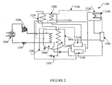
- FIG. 2 therein is illustrated another embodiment of the present invention, this embodiment being represented by numeral 200 in Figure 2 .
- the heat reclaimer 120 is not provided and the dilute refrigerant-absorbent solution is simultaneously concentrated in the high temperature generator 122b and the low temperature generator 126b.
- the dilute refrigerant-absorbent solution leaving the absorber 108b is bifurcated into a first stream and a second stream.
- the first stream of the dilute refrigerant-absorbent solution is again bifurcated into a first part and a second part, wherein the first part of the dilute refrigerant-absorbent solution is fed to the low temperature heat exchanger 114b and the second part of the dilute refrigerant-absorbent solution is fed to the drain heat exchanger 116b.
- the first part and the second part of the dilute refrigerant-absorbent solution gains heat, to become partly heated.
- the partly heated first part of the dilute refrigerant-absorbent solution from the low temperature heat exchanger 114b and the partly heated second part of the dilute refrigerant-absorbent solution from the drain heat exchanger 116b is combined and fed to the low temperature generator 126b.
- the second stream of the dilute refrigerant-absorbent solution is fed to the high temperature generator 122b via the high temperature heat exchanger 118b, where, in the high temperature heat exchanger 118b, the dilute refrigerant-absorbent solution gains heat to become a heated dilute refrigerant-absorbent solution.
- the heated dilute refrigerant-absorbent solution is boiled in the high temperature generator 122b using the heat input 128b, so as to vaporize the refrigerant, to provide a concentrated heated refrigerant-absorbent solution and secondary refrigerant vapors.
- the concentrated heated refrigerant-absorbent solution is circulated through the high temperature heat exchanger 118b, where it rejects heat to the second stream of the dilute refrigerant-absorbent solution, to become a first portion of concentrated refrigerant-absorbent solution.
- the secondary refrigerant vapors are received in the low temperature generator 126b via line 124b, where it acts as a heat source for concentrating the partly heated dilute refrigerant-absorbent solution received therein, to provide a concentrated partly heated refrigerant-absorbent solution and a secondary refrigerant condensate.
- the concentrated partly heated refrigerant-absorbent solution rejects heat in the low temperature heat exchanger 114b to the first part of the dilute refrigerant-absorbent solution, to become a second portion of concentrated refrigerant-absorbent solution.
- the first portion and the second portion of concentrated refrigerant-absorbent solution are combined and sprayed in the absorber 108b.
- the secondary refrigerant condensate is circulated through the drain heat exchanger 116b, where it rejects heat to the second part of the dilute refrigerant-absorbent solution, to become cooled secondary refrigerant condensate.
- the cooled secondary refrigerant condensate is conveyed to the condenser 112b, where it further condenses, to provide the low temperature condensed secondary refrigerant, which is sprayed in the secondary evaporator 106b, thereby completing the second loop.
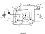
- FIG. 3 therein is illustrated yet another embodiment of the present invention, this embodiment being represented by numeral 300 in Figure 3 .
- the heat reclaimer 120 is not provided and the dilute refrigerant-absorbent solution is simultaneously concentrated in the high temperature generator 122c and the low temperature generator 126c.
- the dilute refrigerant-absorbent solution leaving the absorber 108c is bifurcated, a first stream is fed to the low temperature heat exchanger 114c and a second stream is fed to the drain heat exchanger 116c, where the dilute refrigerant-absorbent solution gains heat to become partly heated.
- the partly heated first stream and the partly heated second stream of the dilute refrigerant-absorbent solution, leaving the low temperature heat exchanger 114c and the drain heat exchanger 116c, respectively, are combined, to provide a single stream of partly heated dilute refrigerant-absorbent solution.
- This single stream is bifurcated into a first portion and a second portion, wherein the first portion of partly heated dilute refrigerant-absorbent solution is conveyed to the low temperature generator 126c and the second portion of partly heated dilute refrigerant-absorbent solution is circulated through the high temperature heat exchanger 118c.
- the second portion of the partly heated dilute refrigerant-absorbent solution gains heat, to become a heated dilute refrigerant-absorbent solution.
- the heated dilute refrigerant-absorbent solution is conveyed to the high temperature generator 122c, where by using the heat input 128c, the heated dilute refrigerant-absorbent solution is boiled so as to vaporize the refrigerant, and provide a concentrated heated refrigerant-absorbent solution and secondary refrigerant vapors.
- the concentrated heated refrigerant-absorbent solution is circulated through the high temperature heat exchanger 118c, where it rejects partial heat to the second portion of partly heated dilute refrigerant-absorbent solution, to become a first stream of concentrated partly heated refrigerant-absorbent solution.
- the secondary refrigerant vapors are received in the low temperature generator 126c via line 124c, where the vapors act as a heat source for concentrating the first portion of partly heated dilute refrigerant-absorbent solution received therein, and provide a second stream of concentrated partly heated refrigerant-absorbent solution and a secondary refrigerant condensate.
- the first stream and the second stream of concentrated partly heated refrigerant-absorbent solution are combined and circulated through the low temperature heat exchanger 114c, wherein the concentrated partly heated refrigerant-absorbent solution rejects heat in the low temperature heat exchanger 114c to the first stream of the dilute refrigerant-absorbent solution, to become a concentrated refrigerant-absorbent solution which is sprayed in the absorber 108c.
- the secondary refrigerant condensate is circulated through the drain heat exchanger 116c, where it rejects heat to the second stream of the dilute refrigerant-absorbent solution, to become cooled secondary refrigerant condensate.
- the cooled secondary refrigerant condensate is conveyed to the condenser 112c, where it further condenses, to provide the low temperature condensed secondary refrigerant, which is sprayed in the secondary evaporator 106c, thereby completing the second loop.
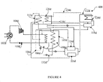
- FIG. 4 therein is illustrated still another embodiment of the present invention, this embodiment being represented by numeral 400 in Figure 4 .
- the heat reclaimer 120 is not provided and the dilute refrigerant-absorbent solution is first concentrated in the low temperature generator 126d and then only a portion is further concentrated in the high temperature generator 122d.
- the dilute refrigerant-absorbent solution leaving the absorber 108d is bifurcated, a first stream is fed to the low temperature heat exchanger 114d and a second stream is fed to the drain heat exchanger 116d, where the dilute refrigerant-absorbent solution gains heat to become partly heated.
- the partly heated first stream and the partly heated second stream of the dilute refrigerant-absorbent solution, leaving the low temperature heat exchanger 114d and the drain heat exchanger 116d, respectively, are combined, to provide a single stream of partly heated dilute refrigerant-absorbent solution.
- This single stream of partly heated dilute refrigerant-absorbent solution is conveyed to the low temperature generator 126d, where, by extracting heat from a heat source, the partly heated dilute refrigerant-absorbent solution gets moderately concentrated, to provide a moderately concentrated partly heated refrigerant-absorbent solution.
- the moderately concentrated partly heated refrigerant-absorbent solution, generated in the low temperature generator 126d, is bifurcated, where, a first portion is circulated through the high temperature heat exchanger 118d and a second portion is circulated through the low temperature heat exchanger 114d.
- the first portion of the moderately concentrated partly heated refrigerant-absorbent solution gains heat in the high temperature heat exchanger 118d, to become a moderately concentrated heated refrigerant-absorbent solution, which is conveyed to the high temperature generator 122d, where, by using heat from the heat input 128d, the refrigerant is vaporized, to provide a concentrated heated refrigerant-absorbent solution and secondary refrigerant vapors which are fed to the low temperature generator 126d as the heat source.
- the concentrated heated refrigerant-absorbent solution is circulated through the high temperature heat exchanger 118d, where, it rejects partial heat to the moderately concentrated partly heated refrigerant-absorbent solution, to become a concentrated partly heated refrigerant absorbent solution.
- This concentrated partly heated refrigerant-absorbent solution is combined with the second portion of moderately concentrated partly heated refrigerant-absorbent solution leaving the low temperature generator 126d, and the mixture is circulated through the low temperature heat exchanger 114d, where it rejects heat to the first stream of dilute refrigerant-absorbent solution, to become concentrated refrigerant-absorbent solution, which is sprayed in the absorber 108d.
- the secondary refrigerant condensate is circulated through the drain heat exchanger 116d, where it rejects heat to the second stream of the dilute refrigerant-absorbent solution, to become cooled secondary refrigerant condensate.
- the cooled secondary refrigerant condensate is conveyed to the condenser 112d, where it further condenses, to provide the low temperature condensed secondary refrigerant, which is sprayed in the secondary evaporator 106d, thereby completing the second loop.
Landscapes
- Engineering & Computer Science (AREA)
- Physics & Mathematics (AREA)
- Mechanical Engineering (AREA)
- Thermal Sciences (AREA)
- General Engineering & Computer Science (AREA)
- Sorption Type Refrigeration Machines (AREA)
Priority Applications (1)
| Application Number | Priority Date | Filing Date | Title |
|---|---|---|---|
| PL11852445T PL2659201T3 (pl) | 2010-12-27 | 2011-11-29 | Hybrydowa chłodziarka absorpcyjno-sprężarkowa i powiązany sposób uzyskiwania działania chłodzącego |
Applications Claiming Priority (2)
| Application Number | Priority Date | Filing Date | Title |
|---|---|---|---|
| IN3547MU2010 | 2010-12-27 | ||
| PCT/IN2011/000819 WO2012090217A2 (en) | 2010-12-27 | 2011-11-29 | Hybrid absorption-compression chiller |
Publications (3)
| Publication Number | Publication Date |
|---|---|
| EP2659201A2 EP2659201A2 (en) | 2013-11-06 |
| EP2659201A4 EP2659201A4 (en) | 2017-04-26 |
| EP2659201B1 true EP2659201B1 (en) | 2021-05-26 |
Family
ID=46383587
Family Applications (1)
| Application Number | Title | Priority Date | Filing Date |
|---|---|---|---|
| EP11852445.3A Active EP2659201B1 (en) | 2010-12-27 | 2011-11-29 | Hybrid absorption-compression chiller and a related method for providing refrigeration effect |
Country Status (7)
| Country | Link |
|---|---|
| US (1) | US9239177B2 (pl) |
| EP (1) | EP2659201B1 (pl) |
| CN (2) | CN103649649A (pl) |
| DK (1) | DK2659201T3 (pl) |
| ES (1) | ES2890330T3 (pl) |
| PL (1) | PL2659201T3 (pl) |
| WO (1) | WO2012090217A2 (pl) |
Families Citing this family (11)
| Publication number | Priority date | Publication date | Assignee | Title |
|---|---|---|---|---|
| US9207003B2 (en) * | 2014-04-02 | 2015-12-08 | King Fahd University Of Petroleum And Minerals | Intermittent absorption system with a liquid-liquid heat exchanger |
| WO2017103939A1 (en) | 2015-12-18 | 2017-06-22 | Bry-Air [Asia] Pvt. Ltd. | Devices with hybrid vapour compression-adsorption cycle and method for implementation thereof |
| DE102016213680A1 (de) | 2016-07-26 | 2018-02-01 | Efficient Energy Gmbh | Wärmepumpensystem mit CO2 als erstem Wärmepumpenmedium und Wasser als zweitem Wärmepumpenmedium |
| DE102016213679A1 (de) | 2016-07-26 | 2018-02-01 | Efficient Energy Gmbh | Wärmepumpensystem mit eingangsseitig und ausgangsseitig gekoppelten Wärmepumpenanordnungen |
| CN110325806A (zh) * | 2016-10-05 | 2019-10-11 | 江森自控科技公司 | 用于hvac&r系统的热泵 |
| CN108954900A (zh) * | 2018-09-18 | 2018-12-07 | 迪茗(上海)智能科技有限公司 | 一种制冷装置及方法 |
| CN110500688B (zh) * | 2019-09-24 | 2024-04-16 | 华北理工大学 | 利用稀释热进行空气调节的稀释式制冷热泵系统 |
| CN116951820A (zh) * | 2023-08-09 | 2023-10-27 | 黄联养 | 共生式制冷制热系统及其工作方法 |
| CN119533000B (zh) * | 2024-10-29 | 2026-01-09 | 同方节能工程技术有限公司 | 一种一体化供冷供蒸汽系统 |
| CN119436609A (zh) * | 2024-11-19 | 2025-02-14 | 浙江大学 | 自冷却型亚临界二氧化碳制冷系统 |
| CN119822428A (zh) * | 2025-01-04 | 2025-04-15 | 北方工业大学 | 一种多级吸收式加湿冷凝净水系统 |
Family Cites Families (19)
| Publication number | Priority date | Publication date | Assignee | Title |
|---|---|---|---|---|
| US3301000A (en) * | 1965-02-15 | 1967-01-31 | Borg Warner | Combination vapor compression and absorption refrigeration system |
| US3824804A (en) | 1973-08-22 | 1974-07-23 | C Sandmark | Refrigerating machines |
| US4329851A (en) * | 1978-06-08 | 1982-05-18 | Carrier Corporation | Absorption refrigeration system |
| JPS5758537Y2 (pl) * | 1979-07-18 | 1982-12-14 | ||
| JPS58129172A (ja) * | 1982-01-29 | 1983-08-02 | 株式会社日立製作所 | 冷却設備 |
| US4745768A (en) * | 1987-08-27 | 1988-05-24 | The Brooklyn Union Gas Company | Combustion-powered refrigeration with decreased fuel consumption |
| JPH083392B2 (ja) * | 1988-08-04 | 1996-01-17 | 株式会社日立製作所 | 濃度差蓄冷熱発生装置 |
| US4873839A (en) * | 1988-10-11 | 1989-10-17 | The Brooklyn Union Gas Company | Combustion-powered compound refrigeration system |
| US4966007A (en) * | 1989-05-12 | 1990-10-30 | Baltimore Aircoil Company, Inc. | Absorption refrigeration method and apparatus |
| JPH0926226A (ja) | 1995-07-11 | 1997-01-28 | Nkk Corp | 冷凍装置 |
| TW325516B (en) * | 1996-04-25 | 1998-01-21 | Chugoku Electric Power | Compression/absorption combined type heat pump |
| US6631624B1 (en) * | 2000-11-10 | 2003-10-14 | Rocky Research | Phase-change heat transfer coupling for aqua-ammonia absorption systems |
| JP2006183889A (ja) * | 2004-12-27 | 2006-07-13 | Nissan Motor Light Truck Co Ltd | ヒートポンプ装置 |
| RU2007146973A (ru) | 2005-05-18 | 2009-06-27 | Е.И.Дюпон де Немур энд Компани (US) | Гибридный парокомпрессионно-абсорбционный цикл |
| CN1804511A (zh) * | 2006-01-23 | 2006-07-19 | 李华玉 | 压缩-吸收复合式热泵供热系统 |
| KR100732228B1 (ko) * | 2006-03-06 | 2007-06-27 | 학교법인 포항공과대학교 | 하이브리드 흡수식 냉동기 |
| JP5118835B2 (ja) * | 2006-09-28 | 2013-01-16 | 三洋電機株式会社 | 吸収式冷凍装置 |
| CN201100780Y (zh) * | 2007-10-10 | 2008-08-13 | 梁任雪 | 压缩-吸收混合式制冷机 |
| US8978397B2 (en) * | 2009-04-24 | 2015-03-17 | Thermax Limited | Absorption heat pump employing a high/low pressure evaporator/absorber unit a heat recovery unit |
-
2011
- 2011-11-29 EP EP11852445.3A patent/EP2659201B1/en active Active
- 2011-11-29 PL PL11852445T patent/PL2659201T3/pl unknown
- 2011-11-29 CN CN201180062920.0A patent/CN103649649A/zh active Pending
- 2011-11-29 DK DK11852445.3T patent/DK2659201T3/da active
- 2011-11-29 ES ES11852445T patent/ES2890330T3/es active Active
- 2011-11-29 US US13/976,140 patent/US9239177B2/en active Active
- 2011-11-29 CN CN201810112300.7A patent/CN108413646A/zh active Pending
- 2011-11-29 WO PCT/IN2011/000819 patent/WO2012090217A2/en not_active Ceased
Non-Patent Citations (1)
| Title |
|---|
| None * |
Also Published As
| Publication number | Publication date |
|---|---|
| CN103649649A (zh) | 2014-03-19 |
| EP2659201A4 (en) | 2017-04-26 |
| WO2012090217A2 (en) | 2012-07-05 |
| WO2012090217A3 (en) | 2016-05-26 |
| US9239177B2 (en) | 2016-01-19 |
| EP2659201A2 (en) | 2013-11-06 |
| PL2659201T3 (pl) | 2021-11-22 |
| DK2659201T3 (da) | 2021-08-30 |
| ES2890330T3 (es) | 2022-01-18 |
| US20130269373A1 (en) | 2013-10-17 |
| CN108413646A (zh) | 2018-08-17 |
Similar Documents
| Publication | Publication Date | Title |
|---|---|---|
| US9239177B2 (en) | Hybrid absorption-compression chiller | |
| US8978397B2 (en) | Absorption heat pump employing a high/low pressure evaporator/absorber unit a heat recovery unit | |
| US11940187B2 (en) | Water treatment system of coupling heat pump with multi-effect evaporation and operating method thereof | |
| CN101344345B (zh) | 压缩-吸收-扩散复合式制冷装置及其制冷循环方法 | |
| CN101968288B (zh) | 一种吸收-压缩复合制冷循环系统 | |
| US20040237527A1 (en) | Exhaust heat recovery system | |
| US8839635B2 (en) | High efficiency double-effect chiller heater apparatus | |
| CN105674558B (zh) | 燃气机驱动蒸气压缩与吸收复合式热泵热水机组运行方法 | |
| CN103438598B (zh) | 基于正逆循环耦合的复叠式制冷系统及方法 | |
| JPH02306067A (ja) | 吸収式冷凍法 | |
| CN103743150A (zh) | 吸收压缩式自复叠制冷系统及使用方法 | |
| JP2011099640A (ja) | ハイブリッドヒートポンプ | |
| CN201100780Y (zh) | 压缩-吸收混合式制冷机 | |
| CN112747494B (zh) | 两级与双效复合型溴化锂吸收式冷水机组 | |
| KR101218547B1 (ko) | 복합 냉동기 | |
| JP2004190885A (ja) | 吸収圧縮冷凍装置及び冷凍システム | |
| EP2549205A2 (en) | Triple-effect vapor absorption refrigeration system | |
| CN2913969Y (zh) | 压缩式、吸收式联合制冷装置 | |
| CN109442804B (zh) | 一种深度冷凝乏汽的双级压缩热泵循环系统 | |
| KR100634843B1 (ko) | 냉동기 | |
| CN101603747A (zh) | 一种吸收式制冷循环方法 | |
| CN113587491B (zh) | 一种双级发生吸收式热泵空调装置 | |
| JP2004069276A (ja) | 廃熱回収式冷却システム | |
| CN1220014C (zh) | 双吸收吸收式制冷装置 | |
| CN112402995B (zh) | 一种应用于切削液浓缩的空气源多效真空式蒸发系统 |
Legal Events
| Date | Code | Title | Description |
|---|---|---|---|
| PUAI | Public reference made under article 153(3) epc to a published international application that has entered the european phase |
Free format text: ORIGINAL CODE: 0009012 |
|
| 17P | Request for examination filed |
Effective date: 20130614 |
|
| AK | Designated contracting states |
Kind code of ref document: A2 Designated state(s): AL AT BE BG CH CY CZ DE DK EE ES FI FR GB GR HR HU IE IS IT LI LT LU LV MC MK MT NL NO PL PT RO RS SE SI SK SM TR |
|
| DAX | Request for extension of the european patent (deleted) | ||
| R17D | Deferred search report published (corrected) |
Effective date: 20160526 |
|
| A4 | Supplementary search report drawn up and despatched |
Effective date: 20170328 |
|
| RIC1 | Information provided on ipc code assigned before grant |
Ipc: F25B 15/00 20060101ALI20170322BHEP Ipc: F25B 3/00 20060101AFI20170322BHEP Ipc: F25B 39/02 20060101ALI20170322BHEP Ipc: F25B 25/02 20060101ALI20170322BHEP Ipc: F25B 35/02 20060101ALI20170322BHEP |
|
| STAA | Information on the status of an ep patent application or granted ep patent |
Free format text: STATUS: EXAMINATION IS IN PROGRESS |
|
| 17Q | First examination report despatched |
Effective date: 20190205 |
|
| GRAJ | Information related to disapproval of communication of intention to grant by the applicant or resumption of examination proceedings by the epo deleted |
Free format text: ORIGINAL CODE: EPIDOSDIGR1 |
|
| STAA | Information on the status of an ep patent application or granted ep patent |
Free format text: STATUS: GRANT OF PATENT IS INTENDED |
|
| GRAP | Despatch of communication of intention to grant a patent |
Free format text: ORIGINAL CODE: EPIDOSNIGR1 |
|
| INTG | Intention to grant announced |
Effective date: 20201214 |
|
| GRAS | Grant fee paid |
Free format text: ORIGINAL CODE: EPIDOSNIGR3 |
|
| GRAA | (expected) grant |
Free format text: ORIGINAL CODE: 0009210 |
|
| STAA | Information on the status of an ep patent application or granted ep patent |
Free format text: STATUS: THE PATENT HAS BEEN GRANTED |
|
| AK | Designated contracting states |
Kind code of ref document: B1 Designated state(s): AL AT BE BG CH CY CZ DE DK EE ES FI FR GB GR HR HU IE IS IT LI LT LU LV MC MK MT NL NO PL PT RO RS SE SI SK SM TR |
|
| REG | Reference to a national code |
Ref country code: GB Ref legal event code: FG4D |
|
| REG | Reference to a national code |
Ref country code: CH Ref legal event code: EP |
|
| REG | Reference to a national code |
Ref country code: AT Ref legal event code: REF Ref document number: 1396620 Country of ref document: AT Kind code of ref document: T Effective date: 20210615 |
|
| REG | Reference to a national code |
Ref country code: DE Ref legal event code: R096 Ref document number: 602011071041 Country of ref document: DE |
|
| REG | Reference to a national code |
Ref country code: IE Ref legal event code: FG4D |
|
| REG | Reference to a national code |
Ref country code: DK Ref legal event code: T3 Effective date: 20210826 |
|
| REG | Reference to a national code |
Ref country code: LT Ref legal event code: MG9D |
|
| REG | Reference to a national code |
Ref country code: SE Ref legal event code: TRGR |
|
| REG | Reference to a national code |
Ref country code: AT Ref legal event code: MK05 Ref document number: 1396620 Country of ref document: AT Kind code of ref document: T Effective date: 20210526 |
|
| PG25 | Lapsed in a contracting state [announced via postgrant information from national office to epo] |
Ref country code: FI Free format text: LAPSE BECAUSE OF FAILURE TO SUBMIT A TRANSLATION OF THE DESCRIPTION OR TO PAY THE FEE WITHIN THE PRESCRIBED TIME-LIMIT Effective date: 20210526 Ref country code: LT Free format text: LAPSE BECAUSE OF FAILURE TO SUBMIT A TRANSLATION OF THE DESCRIPTION OR TO PAY THE FEE WITHIN THE PRESCRIBED TIME-LIMIT Effective date: 20210526 Ref country code: BG Free format text: LAPSE BECAUSE OF FAILURE TO SUBMIT A TRANSLATION OF THE DESCRIPTION OR TO PAY THE FEE WITHIN THE PRESCRIBED TIME-LIMIT Effective date: 20210826 Ref country code: AT Free format text: LAPSE BECAUSE OF FAILURE TO SUBMIT A TRANSLATION OF THE DESCRIPTION OR TO PAY THE FEE WITHIN THE PRESCRIBED TIME-LIMIT Effective date: 20210526 Ref country code: HR Free format text: LAPSE BECAUSE OF FAILURE TO SUBMIT A TRANSLATION OF THE DESCRIPTION OR TO PAY THE FEE WITHIN THE PRESCRIBED TIME-LIMIT Effective date: 20210526 |
|
| REG | Reference to a national code |
Ref country code: NL Ref legal event code: MP Effective date: 20210526 |
|
| PG25 | Lapsed in a contracting state [announced via postgrant information from national office to epo] |
Ref country code: PT Free format text: LAPSE BECAUSE OF FAILURE TO SUBMIT A TRANSLATION OF THE DESCRIPTION OR TO PAY THE FEE WITHIN THE PRESCRIBED TIME-LIMIT Effective date: 20210927 Ref country code: NO Free format text: LAPSE BECAUSE OF FAILURE TO SUBMIT A TRANSLATION OF THE DESCRIPTION OR TO PAY THE FEE WITHIN THE PRESCRIBED TIME-LIMIT Effective date: 20210826 Ref country code: RS Free format text: LAPSE BECAUSE OF FAILURE TO SUBMIT A TRANSLATION OF THE DESCRIPTION OR TO PAY THE FEE WITHIN THE PRESCRIBED TIME-LIMIT Effective date: 20210526 Ref country code: LV Free format text: LAPSE BECAUSE OF FAILURE TO SUBMIT A TRANSLATION OF THE DESCRIPTION OR TO PAY THE FEE WITHIN THE PRESCRIBED TIME-LIMIT Effective date: 20210526 Ref country code: GR Free format text: LAPSE BECAUSE OF FAILURE TO SUBMIT A TRANSLATION OF THE DESCRIPTION OR TO PAY THE FEE WITHIN THE PRESCRIBED TIME-LIMIT Effective date: 20210827 Ref country code: IS Free format text: LAPSE BECAUSE OF FAILURE TO SUBMIT A TRANSLATION OF THE DESCRIPTION OR TO PAY THE FEE WITHIN THE PRESCRIBED TIME-LIMIT Effective date: 20210926 |
|
| PG25 | Lapsed in a contracting state [announced via postgrant information from national office to epo] |
Ref country code: NL Free format text: LAPSE BECAUSE OF FAILURE TO SUBMIT A TRANSLATION OF THE DESCRIPTION OR TO PAY THE FEE WITHIN THE PRESCRIBED TIME-LIMIT Effective date: 20210526 |
|
| REG | Reference to a national code |
Ref country code: ES Ref legal event code: FG2A Ref document number: 2890330 Country of ref document: ES Kind code of ref document: T3 Effective date: 20220118 |
|
| PG25 | Lapsed in a contracting state [announced via postgrant information from national office to epo] |
Ref country code: EE Free format text: LAPSE BECAUSE OF FAILURE TO SUBMIT A TRANSLATION OF THE DESCRIPTION OR TO PAY THE FEE WITHIN THE PRESCRIBED TIME-LIMIT Effective date: 20210526 Ref country code: CZ Free format text: LAPSE BECAUSE OF FAILURE TO SUBMIT A TRANSLATION OF THE DESCRIPTION OR TO PAY THE FEE WITHIN THE PRESCRIBED TIME-LIMIT Effective date: 20210526 Ref country code: SK Free format text: LAPSE BECAUSE OF FAILURE TO SUBMIT A TRANSLATION OF THE DESCRIPTION OR TO PAY THE FEE WITHIN THE PRESCRIBED TIME-LIMIT Effective date: 20210526 Ref country code: SM Free format text: LAPSE BECAUSE OF FAILURE TO SUBMIT A TRANSLATION OF THE DESCRIPTION OR TO PAY THE FEE WITHIN THE PRESCRIBED TIME-LIMIT Effective date: 20210526 Ref country code: RO Free format text: LAPSE BECAUSE OF FAILURE TO SUBMIT A TRANSLATION OF THE DESCRIPTION OR TO PAY THE FEE WITHIN THE PRESCRIBED TIME-LIMIT Effective date: 20210526 |
|
| REG | Reference to a national code |
Ref country code: DE Ref legal event code: R097 Ref document number: 602011071041 Country of ref document: DE |
|
| PLBE | No opposition filed within time limit |
Free format text: ORIGINAL CODE: 0009261 |
|
| STAA | Information on the status of an ep patent application or granted ep patent |
Free format text: STATUS: NO OPPOSITION FILED WITHIN TIME LIMIT |
|
| 26N | No opposition filed |
Effective date: 20220301 |
|
| PG25 | Lapsed in a contracting state [announced via postgrant information from national office to epo] |
Ref country code: IS Free format text: LAPSE BECAUSE OF FAILURE TO SUBMIT A TRANSLATION OF THE DESCRIPTION OR TO PAY THE FEE WITHIN THE PRESCRIBED TIME-LIMIT Effective date: 20210926 Ref country code: AL Free format text: LAPSE BECAUSE OF FAILURE TO SUBMIT A TRANSLATION OF THE DESCRIPTION OR TO PAY THE FEE WITHIN THE PRESCRIBED TIME-LIMIT Effective date: 20210526 |
|
| PG25 | Lapsed in a contracting state [announced via postgrant information from national office to epo] |
Ref country code: MC Free format text: LAPSE BECAUSE OF FAILURE TO SUBMIT A TRANSLATION OF THE DESCRIPTION OR TO PAY THE FEE WITHIN THE PRESCRIBED TIME-LIMIT Effective date: 20210526 |
|
| PG25 | Lapsed in a contracting state [announced via postgrant information from national office to epo] |
Ref country code: LU Free format text: LAPSE BECAUSE OF NON-PAYMENT OF DUE FEES Effective date: 20211129 Ref country code: BE Free format text: LAPSE BECAUSE OF NON-PAYMENT OF DUE FEES Effective date: 20211130 |
|
| REG | Reference to a national code |
Ref country code: BE Ref legal event code: MM Effective date: 20211130 |
|
| PG25 | Lapsed in a contracting state [announced via postgrant information from national office to epo] |
Ref country code: IE Free format text: LAPSE BECAUSE OF NON-PAYMENT OF DUE FEES Effective date: 20211129 |
|
| PG25 | Lapsed in a contracting state [announced via postgrant information from national office to epo] |
Ref country code: HU Free format text: LAPSE BECAUSE OF FAILURE TO SUBMIT A TRANSLATION OF THE DESCRIPTION OR TO PAY THE FEE WITHIN THE PRESCRIBED TIME-LIMIT; INVALID AB INITIO Effective date: 20111129 Ref country code: CY Free format text: LAPSE BECAUSE OF FAILURE TO SUBMIT A TRANSLATION OF THE DESCRIPTION OR TO PAY THE FEE WITHIN THE PRESCRIBED TIME-LIMIT Effective date: 20210526 |
|
| PG25 | Lapsed in a contracting state [announced via postgrant information from national office to epo] |
Ref country code: MK Free format text: LAPSE BECAUSE OF FAILURE TO SUBMIT A TRANSLATION OF THE DESCRIPTION OR TO PAY THE FEE WITHIN THE PRESCRIBED TIME-LIMIT Effective date: 20210526 |
|
| PG25 | Lapsed in a contracting state [announced via postgrant information from national office to epo] |
Ref country code: MT Free format text: LAPSE BECAUSE OF FAILURE TO SUBMIT A TRANSLATION OF THE DESCRIPTION OR TO PAY THE FEE WITHIN THE PRESCRIBED TIME-LIMIT Effective date: 20210526 |
|
| PGFP | Annual fee paid to national office [announced via postgrant information from national office to epo] |
Ref country code: PL Payment date: 20250527 Year of fee payment: 14 Ref country code: DE Payment date: 20250527 Year of fee payment: 14 |
|
| PGFP | Annual fee paid to national office [announced via postgrant information from national office to epo] |
Ref country code: GB Payment date: 20250527 Year of fee payment: 14 Ref country code: DK Payment date: 20250527 Year of fee payment: 14 Ref country code: ES Payment date: 20250528 Year of fee payment: 14 |
|
| PGFP | Annual fee paid to national office [announced via postgrant information from national office to epo] |
Ref country code: IT Payment date: 20250527 Year of fee payment: 14 |
|
| PGFP | Annual fee paid to national office [announced via postgrant information from national office to epo] |
Ref country code: FR Payment date: 20250530 Year of fee payment: 14 |
|
| PGFP | Annual fee paid to national office [announced via postgrant information from national office to epo] |
Ref country code: CH Payment date: 20250530 Year of fee payment: 14 |
|
| PGFP | Annual fee paid to national office [announced via postgrant information from national office to epo] |
Ref country code: TR Payment date: 20250527 Year of fee payment: 14 |
|
| PGFP | Annual fee paid to national office [announced via postgrant information from national office to epo] |
Ref country code: SE Payment date: 20250527 Year of fee payment: 14 |