EP2659979A2 - Structure de support pour le support simultané d'une pluralité de récipients pour des applications médicales, pharmaceutiques ou cosmétiques ainsi que récipient de transport ou d'emballage - Google Patents
Structure de support pour le support simultané d'une pluralité de récipients pour des applications médicales, pharmaceutiques ou cosmétiques ainsi que récipient de transport ou d'emballage Download PDFInfo
- Publication number
- EP2659979A2 EP2659979A2 EP13166537.4A EP13166537A EP2659979A2 EP 2659979 A2 EP2659979 A2 EP 2659979A2 EP 13166537 A EP13166537 A EP 13166537A EP 2659979 A2 EP2659979 A2 EP 2659979A2
- Authority
- EP
- European Patent Office
- Prior art keywords
- containers
- support structure
- receptacles
- container
- transport
- Prior art date
- Legal status (The legal status is an assumption and is not a legal conclusion. Google has not performed a legal analysis and makes no representation as to the accuracy of the status listed.)
- Granted
Links
Images





Classifications
-
- A—HUMAN NECESSITIES
- A61—MEDICAL OR VETERINARY SCIENCE; HYGIENE
- A61J—CONTAINERS SPECIALLY ADAPTED FOR MEDICAL OR PHARMACEUTICAL PURPOSES; DEVICES OR METHODS SPECIALLY ADAPTED FOR BRINGING PHARMACEUTICAL PRODUCTS INTO PARTICULAR PHYSICAL OR ADMINISTERING FORMS; DEVICES FOR ADMINISTERING FOOD OR MEDICINES ORALLY; BABY COMFORTERS; DEVICES FOR RECEIVING SPITTLE
- A61J1/00—Containers specially adapted for medical or pharmaceutical purposes
- A61J1/14—Details; Accessories therefor
- A61J1/18—Arrangements for indicating condition of container contents, e.g. sterile condition
-
- B—PERFORMING OPERATIONS; TRANSPORTING
- B01—PHYSICAL OR CHEMICAL PROCESSES OR APPARATUS IN GENERAL
- B01L—CHEMICAL OR PHYSICAL LABORATORY APPARATUS FOR GENERAL USE
- B01L9/00—Supporting devices; Holding devices
- B01L9/06—Test-tube stands; Test-tube holders
-
- A—HUMAN NECESSITIES
- A61—MEDICAL OR VETERINARY SCIENCE; HYGIENE
- A61J—CONTAINERS SPECIALLY ADAPTED FOR MEDICAL OR PHARMACEUTICAL PURPOSES; DEVICES OR METHODS SPECIALLY ADAPTED FOR BRINGING PHARMACEUTICAL PRODUCTS INTO PARTICULAR PHYSICAL OR ADMINISTERING FORMS; DEVICES FOR ADMINISTERING FOOD OR MEDICINES ORALLY; BABY COMFORTERS; DEVICES FOR RECEIVING SPITTLE
- A61J1/00—Containers specially adapted for medical or pharmaceutical purposes
- A61J1/14—Details; Accessories therefor
-
- A—HUMAN NECESSITIES
- A61—MEDICAL OR VETERINARY SCIENCE; HYGIENE
- A61M—DEVICES FOR INTRODUCING MEDIA INTO, OR ONTO, THE BODY; DEVICES FOR TRANSDUCING BODY MEDIA OR FOR TAKING MEDIA FROM THE BODY; DEVICES FOR PRODUCING OR ENDING SLEEP OR STUPOR
- A61M5/00—Devices for bringing media into the body in a subcutaneous, intra-vascular or intramuscular way; Accessories therefor, e.g. filling or cleaning devices, arm-rests
- A61M5/001—Apparatus specially adapted for cleaning or sterilising syringes or needles
-
- B—PERFORMING OPERATIONS; TRANSPORTING
- B01—PHYSICAL OR CHEMICAL PROCESSES OR APPARATUS IN GENERAL
- B01L—CHEMICAL OR PHYSICAL LABORATORY APPARATUS FOR GENERAL USE
- B01L2200/00—Solutions for specific problems relating to chemical or physical laboratory apparatus
- B01L2200/02—Adapting objects or devices to another
- B01L2200/021—Adjust spacings in an array of wells, pipettes or holders, format transfer between arrays of different size or geometry
- B01L2200/022—Variable spacings
-
- B—PERFORMING OPERATIONS; TRANSPORTING
- B01—PHYSICAL OR CHEMICAL PROCESSES OR APPARATUS IN GENERAL
- B01L—CHEMICAL OR PHYSICAL LABORATORY APPARATUS FOR GENERAL USE
- B01L2200/00—Solutions for specific problems relating to chemical or physical laboratory apparatus
- B01L2200/08—Ergonomic or safety aspects of handling devices
- B01L2200/087—Ergonomic aspects
-
- B—PERFORMING OPERATIONS; TRANSPORTING
- B01—PHYSICAL OR CHEMICAL PROCESSES OR APPARATUS IN GENERAL
- B01L—CHEMICAL OR PHYSICAL LABORATORY APPARATUS FOR GENERAL USE
- B01L2200/00—Solutions for specific problems relating to chemical or physical laboratory apparatus
- B01L2200/18—Transport of container or devices
-
- B—PERFORMING OPERATIONS; TRANSPORTING
- B01—PHYSICAL OR CHEMICAL PROCESSES OR APPARATUS IN GENERAL
- B01L—CHEMICAL OR PHYSICAL LABORATORY APPARATUS FOR GENERAL USE
- B01L2300/00—Additional constructional details
- B01L2300/08—Geometry, shape and general structure
- B01L2300/0848—Specific forms of parts of containers
- B01L2300/0858—Side walls
Definitions
- the present invention relates generally to the simultaneous mounting of a plurality of containers for storing substances for medical, pharmaceutical or cosmetic applications, in particular of vials, and more particularly relates to the simultaneous mounting of a plurality of containers in a holding structure in such a way that they while they are held in a holding structure provided for this purpose, can be further processed in filling or processing plants, in particular in a sterile tunnel, a filling plant for liquid medical or pharmaceutical applications or a freeze-drying cabinet for this purpose. Furthermore, the present invention relates to a transport and / or packaging container with at least one such support structure and optionally with an integrated sensor and / or plagiarism protection.
- medicine containers such as vials, ampoules or carpules are widely used. These generally have a cylindrical shape, can be made of plastics or glass and are available in large quantities at low cost.
- concepts are increasingly used in which the containers are packaged sterile sterile at the manufacturer of containers in transport and packaging containers, which then at a pharmaceutical company under sterile conditions, especially in a so-called. Sterile tunnel , unpacked and then processed further.
- Transport and packaging containers are known from the prior art, in which at the same time a plurality of drug containers in a regular arrangement, for example, in a matrix array along rows and at right angles to extending columns, are arranged.
- This has advantages in the automated further processing of the containers, since the containers can be transferred to processing stations in controlled positions and in a predetermined arrangement, for example to process machines, robots or the like.
- holding structures are used, in which at the same time a plurality of containers can be held in a predetermined regular arrangement. To transfer to a processing station just needs the transport and packaging container to be properly positioned and opened. The downstream processing station then knows in which position and arrangement the containers to be further processed are arranged.
- Such a transport and packaging container and a corresponding packaging concept are for example in the US 8,118,167 B2 disclosed.
- the further processing of the container always takes place in such a way that the holding structure from the transport and packaging container, the container is removed from the support structure and separated and transferred to a conveyor, in particular a conveyor belt, individually to the processing stations and further processed there.
- US 8,100,263 B2 discloses a sterile packable and transportable transport and packaging container in which a plate-shaped support structure can be used, in which a plurality of drug containers are kept in a regular arrangement.
- the individual medication containers are initially arranged loosely in receptacles which are formed in the holding structure.
- the support structure is inserted into the transport and packaging container and this surrounded with a gas-impermeable plastic tube.
- the plastic tube is pressed into the spaces between the medicament containers due to the negative pressure prevailing in the tube, which is the case on the one hand leads to a stabilization of the position of the drug container in the support structure and on the other hand prevents further uncontrolled collision of adjacent drug containers.
- the drug container When evacuating and the subsequent opening of the plastic tube, however, the drug container can slip sideways, which increases the automation effort for further processing of the drug container. Furthermore, the drug container after opening the plastic tube can still collide uncontrollably, which brings the aforementioned disadvantages.
- the medicine containers can not be further processed in the transport or packaging container or in the holding structure, but must first be separated in the conventional manner and handed over to downstream processing stations.
- Applicant discloses the clamping of syringe bodies in a plastic carrier plate. Around the openings of the carrier plate around circumferential projections are formed which act as a holding means and serve a further clamping. A coordinated adjustment of the opening width of these openings is not possible because the carrier plate is rigid.
- US 5,950,832 discloses a support structure for centrifuge tubes which are tapered at their lower end.
- the holding structure has an elastic part and a rigid part.
- the diameter of holes of the elastic member is smaller than the outer diameter of the centrifuge tubes, whereby their clamping is made possible. A coordinated adjustment of the opening width of these holes is not disclosed.
- WO 2009/015862 A1 discloses a clamping in the region of the side wall of containers or at the neck portion by retaining means. A coordinated adjustment of the opening width of these holding means is not disclosed.
- GB 2478703 A discloses a support structure consisting of two parts which can be folded on each other.
- the receptacles of the two parts are offset from each other, so that the containers are nested in order to double the packing density, but to allow in the unfolded position a good access to the container.
- Object of the present invention is to develop a holding structure for simultaneously holding a plurality of containers for substances for medical or pharmaceutical applications, in particular of glass vials, to the effect that the container can be easily and inexpensively packaged sterile, unpacked and processed further.
- a support structure should be designed in particular for further processing of the containers while they are being held in the support structure.
- a corresponding transport and packaging container should also be provided with at least one such holding structure.
- the container In a holding structure according to the invention, the container (container) are held in the holding structure frictionally or clamped.
- receptacles For frictional or frictional mounting of cylindrical containers are receptacles, which are preferably formed circumferentially and extending in the longitudinal direction of the container. Force or frictional connections are known to require only sufficient normal force on the surfaces to be joined together. The mutual displacement between the container and the support structure is thus prevented as long as caused by the static friction between the support structure and the container counterforce is not exceeded. The force or friction is lost and the surfaces slip on each other when the tangential load force is greater than the static friction force.
- the force or friction fit is expediently carried out either below the flared upper edge of the container, ie in its narrow neck or neck region below the upper edge, or in the region of the cylindrical side wall.
- a base-side support of the containers is fundamentally not required, so that access to the undersides (bottoms) of the containers held in the holding structure is basically possible. This makes it possible, according to the invention, for the containers to be further processed while they are being held in the holding structure.
- the containers may be batch processed in the holding structures, but remain reliably and collision-free in the holding structures during further processing, allowing significant speed advantages and automation advantages of further processing equipment, thus resulting in even more economical and cost-effective processes .
- the containers can be raised or rotated axially in the holding structure.
- the containers can also be lyophilized in the holding structure, since a direct contact with the ground to a cooling finger of the freeze-drying cabinet is possible. Trays or heads of the containers can be fixed in a simple manner at a height, so that all trays can be arranged in a jointly spanned plane, resulting in direct contact with flat processing stations, in particular to a cold finger or adehorde a freezer cabinet allows.
- the holding structure according to the invention expediently allows the removal of the container up or down. Since the position of the force or frictional connection between the container and holding structure can be varied easily, the holding structure according to the invention can be used very flexibly also for containers with different external dimensions, as long as a sufficient normal force for the frictional engagement can be ensured. In particular, the containers in the support structure can be easily displaced in the axial direction, so that containers with different heights can be held in the same holding structure. The axial mobility of the container in the support structure also allows easy tolerance compensation.
- the receptacles are formed by continuously formed side walls, which is to mean in particular that the side walls of the receptacles are each not formed in multiple pieces, in particular not two or more displaceably mounted relative to each other side wall sections. Rather, the sidewalls are plate-shaped and integral, which should not preclude the sidewalls from being coated with a coating, such as a high coefficient of friction coating, to increase the friction between the sidewalls of the receptacles and the containers, thus making the containers even more effective to pinch.
- a coating such as a high coefficient of friction coating
- the opening width or the frictional engagement of all recordings of the support structure can be adjusted jointly or coordinated by coordinated adjustment of the side walls of the receptacles.
- all recordings of the support structure are preferably mechanically coupled to each other, so that an adjustment or deformation of the support structure leads to a coordinated adjustment of the opening width of all recordings.
- the coordinated adjustment is designed so that the side walls of the receptacles between a first position in which the container with little effort in the openings or receptacles of the support structure are inserted, and a second Coordinated position are adjustable, in which the containers are frictionally fixed in the openings or receptacles of the support structure.
- the containers may be further processed while they are received in the support structure and in the transport and packaging container. If, in spite of all precautionary measures, a container still breaks, this does not lead to contamination of the system, since the break but also any active substances or solutions remain in the transport and packaging container.
- At least a majority of the bottoms or lower ends of the containers are freely accessible from an underside of the support structure.
- the bottoms or lower ends of the containers are not covered by support structures or the like.
- a holding web or the like may be provided at the lower end of the openings of the support structure to support the bottoms or lower ends of the containers.
- an adjusting device for example an adjusting finger, act on the bottoms or lower ends of the containers from the underside of the holding structure in order to axially adjust or also rotate them while they are held in the holding structure.
- the containers may be suitably raised in the support structure and further processed in the raised position and while held in the support structure, for example, provided with an outer closure (crimp cap or staple).
- an outer closure crimp cap or staple
- the opening width of the holding means in particular the opening width of openings or receptacles of the holding means can be adjusted, as explained below, so that the frictional engagement is canceled or substantially reduced at a larger opening width and in accordance with further embodiments a smaller opening width for reliably holding the container persists.
- the elongated receptacles of the support structure for holding the containers may basically have a closed or substantially closed bottom, whereupon the bottoms or lower ends of the containers may be supported.
- the lower end of the receptacles is completely or substantially completely formed.
- a support on a floor or holding web at the lower end of the recordings is not essential, since according to the invention, the holder of the container is accomplished by means of a frictional engagement.
- the frictional engagement is preferably accomplished in such elongated receptacles by the interaction of side walls of the receptacles, preferably of diametrically opposed side walls, with portions of the cylindrical side wall or the neck portion of the container.
- the recordings may have a polygonal cross section, in particular a quadrangular or hexagonal cross section.
- the receptacles can also have a circular or elliptical cross-section, for example when retaining webs are provided at the lower end of the receptacles, which spread apart the side walls of the receptacles, if the retaining structure is not held in place by detent rails or the like (kept taut).
- Another aspect of the present invention further relates to a transport and packaging container having at least one support structure as set forth above and further disclosed in detail below.
- Another aspect of the present invention further relates to a transport and packaging container with measures for plagiarism protection, in particular for identification and / or tracking, as explained below.
- a holding structure and a transport and packaging container which accommodates such a support structure, according to the present invention, as described below, the simultaneous support of a plurality of containers for storing substances for cosmetic, medical or pharmaceutical applications in a regular arrangement, in particular a matrix arrangement at regular intervals of the container to each other, along two different spatial directions, preferably along two mutually orthogonal spatial directions.
- the vials 2 have a cylindrical basic shape, with a cylindrical side wall 4 with - within the tolerances - constant inside and outside diameter, which protrudes perpendicularly from a flat bottle bottom 3 and near the upper open end of the vial in a narrowed neck portion 5 of comparatively small axial length and then merges into a widened upper edge 6, which has a larger outer diameter than the associated neck portion 5 and is designed for connection to a closure element.
- the neck portion 5 may be formed smooth-walled without external thread or may be provided with an external thread for screwing a closure element.
- a plug (not shown) can be inserted, whose upper end with the upper edge 6 of the vial gastight and protected against the ingress of contaminants in the vial is connected to the upper edge 6, for example by crimping a metal protective foil, not shown.
- Such vials are radially symmetrical and formed of a transparent or colored glass or by blow molding or plastic injection molding techniques of a suitable plastic material, and may in principle be internally coated, so that the material of the vial emits as little impurities to the male substance.
- Ampoules or cartridges are containers for pharmaceuticals for the most parenteral application (injection), for cosmetics and other substances and are usually cylindrically shaped with a solid tip (spit or head) and a flat bottom or with two solid tips on both ends.
- These can be designed in particular as crushing ampoules with an annular predetermined breaking point around the ampoule neck or as an OPC ampoule (one-point-cut ampoule) with a scratched into the glass crushing ring.
- Syringes or injection containers also referred to as injection vials, punctured ampoules or reusable ampoules, are cylindrical, bottle-like shaped containers made of glass or plastic, usually in relatively small nominal volumes (eg 1 ml, 10 ml). They are closed with a rubber stopper with septum (puncture rubber). To protect the septum and fix the rubber stopper is still an outer closure (crimp cap or staple), often made of aluminum sheet applied. In a carpule, the liquid is in a cylinder, which is closed at one end with a thick rubber or plastic stopper. This acts as a piston when the contents are squeezed out with a Karpulenspritze.
- the cylinder is closed only with a thin membrane that is pierced in use by the rear end of the cartridge needle (a cannula ground on both sides).
- Cylinder ampoules are often used in dentistry for local anesthesia.
- Special cylindrical ampoules with a specially designed front part eg thread are used for insulin therapy in insulin pens.
- such containers are used for storing substances or active substances for cosmetic, medical or pharmaceutical applications which are to be stored in one or more components in solid or liquid form in the container.
- glass containers can storage periods many years, which depends in particular on the hydrolytic resistance of the type of glass used.
- containers are disclosed below which are cylindrical, it should be noted that the containers according to the present invention may also have a different profile, for example a square, rectangular or polygonal profile.
- such containers due to manufacturing tolerances, which may be just one or several tenths of a millimeter in glass bottles.
- the containers are fixed according to the invention by means of a frictional connection or a clamp on a support structure. This frictional engagement is realized either in the region of the cylindrical side wall 4 or at the lower, closed end or bottom of the container or, according to further preferred embodiments, in the region of the narrowed neck portion 5.
- a holding structure 25 (also referred to as "nest" in the prior art) is provided, which is described below with reference to FIGS FIGS. 1a to 1c is described in more detail and is formed of a plastic, for example, injection molded.
- the holding structure 25 has a plurality of receptacles 39, which extend in the longitudinal direction of the male container 2 and are interconnected.
- the receptacles 39 are also mechanically coupled together.
- the side walls of the receptacles 39 are sufficiently flexible or expandable, so that the container 2 can be inserted from above or from below into the receptacles 39.
- a plurality of containers 2 can be held in a frictionally locked or clamped manner. Due to the elasticity of the side walls of the receptacles, it is also possible to compensate for manufacturing tolerances in the axial and / or radial direction of the containers, in particular in the case of medicament containers made of glass. In particular, containers with different diameters of one and the same holding structure 25 can be fixed by friction.
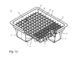
- a transport and packaging container 10 (referred to in the art as so-called "tub"), as shown schematically in the Fig. 1c shown.
- the container 10 is formed substantially box-shaped or trough-shaped and has a bottom 11, a vertically projecting from this, circumferentially formed side wall 12, one of this substantially rectangular projecting step 13, a circumferentially formed upper side wall 14 and an upper edge 15 which is flange-shaped.
- the corners 16 of the container 10 are suitably rounded.
- the upper side wall 14 may be inclined at a slight angle of inclination to the perpendicular to the floor 11 to facilitate insertion of the support structure 25.
- Such a transport and packaging container 10 is preferably formed from a plastic, in particular by plastic injection molding technology, and is preferably formed of a clear, transparent plastic, to provide a visual visual inspection of the received in the transport and packaging container 10 holding structure 25 and of this To allow held container 2.
- the support structure 25 For receiving the support structure 25 in the transport and packaging container 10, the support structure 25 may be surrounded by a support frame having a closed edge web formed.
- the in the Fig. 1c can in principle also be clamped in a holding frame or clamped by this along the edge or can be integrally formed with such a holding frame.
- the support structure 25 and the container 10 may have mutually cooperating positioning structures, which cooperate in particular form-fitting manner.
- Positioning structures in the form of projections or recesses or depressions may be formed at a suitable location, in particular on the step 13 or on support surfaces 18 of the container 10, which form-fit cooperate with correspondingly formed recesses or depressions or projections of the holding structure, around the holding structure 25 to be positioned precisely in the transport container 10.
- a plurality of pin-like projections may be formed on the step 13, which engage in correspondingly formed centering openings in the holding structure.
- the step 13 of the transport container 10 is formed as a circumferential, planar support surface, on which the support structure 25 rests directly.
- the support structure 25 can be precisely positioned in the transport container 10 and the plurality of containers 2 can thus be arranged and held in a regular arrangement and at precisely defined positions in a transport container 10 with standardized dimensions. In particular, it can be ensured in this way that all bottoms of the containers are arranged in a plane spanned jointly parallel to the bottom 11 or to the upper edge 15 of the transport container 10.
- the lower end of the transport container 10 may also be open in the manner of the upper end, in particular provided with a flange-like lower edge in the manner of the upper edge 15 be, so that the bottoms of the container from the bottom of the transport container 10 forth are freely accessible, for example, for processing steps in a sterile tunnel or in a freeze-drying cabinet, as explained in more detail below.
- the plurality of containers 2 are distributed along two mutually orthogonal directions in a plane at predetermined constant distances from each other.
- mutually adjacent rows or columns of containers 2 can also be arranged offset from one another by a predetermined length, specifically in a recurring arrangement with a predetermined periodicity.
- automated manufacturing equipment can expect the container 2 at handover to a processing station at precisely predetermined positions, which significantly reduces the automation effort.
- the containers 2 can also be further processed jointly within the holding structure 25 or the transport container 10, in particular also in a sterile tunnel or a freeze-drying cabinet.
- access openings 29 are formed on two longitudinal sides of the holding structure 25, via which gripper arms or the like can grip the holding structure 25.
- the access openings 29 are arranged offset from one another by one row, which further facilitates one-to-one positioning of the support structure 25 in the transport container 10.
- the Fig. 1b shows a plan view of the packaging unit 1 according to the Fig. 1c
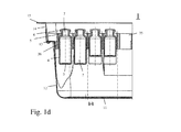
- the Fig. 1d shows a longitudinal section along the line A - A according to the Fig. 1c ,
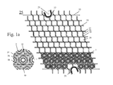
- the Fig. 1a shows a support structure 25 according to a first embodiment according to the present invention.
- This has a plurality of mutually parallel transverse webs 35, which are connected to each other at regular intervals to each other arranged S-shaped connecting webs 36 which extend substantially perpendicular to the transverse webs 35.
- the connecting webs 36 are connected to the transverse webs 35 via front and rear ends 37, 38, which are curved in opposite directions.
- the connecting webs 36 are made of a plastic, preferably of a flexible plastic.
- the transverse webs 35 preferably have a greater rigidity than the connecting webs 36.
- the transverse webs 35 are each offset in the longitudinal direction by a constant distance, so that the holding structure 35 is formed overall as a parallelogram, with a base in the region of the lower edge of the Fig. 1a shown holding structure 25 and two inclined thereto at an acute angle extending imaginary edge lines which connect the front ends of the transverse webs 35 together.
- the container 2 can be introduced freely and without contact with the webs 35, 36 or at least with little effort in the formed by the webs 35, 36 elongated retaining seats 39.
- the retaining seats 39 have substantially a square cross-section, which is matched to the diameter of the container 2, that they are fixed in a second position of the support structure 25 with sufficient force frictionally engaged, in particular can be clamped.
- the transverse webs 35 are each shifted in the longitudinal direction so that finally in the Fig. 1b illustrated rectangular or square support structure 25 is formed. How to compare the Fig. 1a and 1b can be removed, this bend the connecting webs 36 slightly.
- the second position according to the Fig. 1b can by the interaction of the in the support structure 25th trained access openings 29 are fixed with correspondingly formed counter-elements of the container 10 or by the interaction of centering with correspondingly formed centering pin of a holding frame, not shown, which receives the support structure 25.
- the enlarged partial view in the Fig. 1a can be seen that the container 2 in the first position according to the Fig. 1a are loosely received in the holding receptacles 39.
- the enlarged partial view according to the Fig. 1b can be seen that the container 2 in the second position according to the Fig. 1b be frictionally fixed by central portions of the connecting webs 36, in particular clamped. To the transverse webs 35 may continue to exist a certain game, which, however, is preferably minimal or vanishing.
- the Fig. 1c shows the thus formed packaging unit 1 in a perspective partial section, it being understood that in this embodiment, the transverse webs 35 are supported directly on the support surface formed by the step 13 of the container 10.
- the frictional fixing of the container is in the partial section according to the Fig. 1d recognizable.
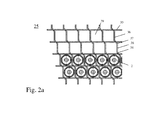
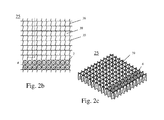
- FIGS. 2a to 2c show the support structure according to another embodiment in a schematic plan view and a perspective view in the aforementioned second position.
- all the side walls of the receptacles 39 when moving the transverse webs 35 are coordinated, ie jointly, adjusted from the first position to the second position, by pivoting the upper end of the support structure 25 (see. Fig. 1a ) relative to the base at the lower end of the Fig. 1a represented parallelogram.
- the containers In the aforementioned first position, the containers can thus be inserted into the support structure and precisely positioned, in particular arranged at a predetermined height level so that all bottoms of the container are flush and arranged in a common plane.
- all containers are then fixed simultaneously frictionally and precisely positioned in a regular arrangement.
- the holding structure according to the Fig. 1a to 1c is preferably formed in one piece from a plastic.
- FIGS. 1e and 1f show in greatly enlarged partial representations of another variant of the support structure according to the Figures 1a-1d , It shows the Fig. 1e the area of a receptacle of the support structure in the aforementioned second position, in which the containers 2 are held in the receptacles of the support structure.
- a concave portion 36a is formed on the connecting webs 36 on the two sides, the radius of curvature of the two concave receptacles of the portions 36a being matched to the radius of the container 2.
- the concave seats 36a nestle against the cylindrical side wall of the containers 2, so that the containers can be kept even more reliable and controlled.
- the concave seats 36a are no longer opposite to the cylindrical side wall of the container 2, so that the container unhindered, at least with significantly reduced force, in the of the webs 35, 36 formed Be introduced and taken out of these recordings.
- the webs 35, 36 are in the first position according to the Fig. 1f not at all on the side walls of the container 2.
- a similar holding structure, as described above with reference to FIGS. 1a-1f can also be assembled from a plurality of identical basic units, as described below with reference to Fig. 3a to 3c described.
- a base unit 100 has cross-shaped side walls 101, 103, 107 with identical leg lengths. Two of the side walls, namely the side walls 101, 103 are slotted, with a longitudinal slot 102 which extends substantially over the entire height of the side walls 101, 103. In the side walls 101, 103, an upper slot 105 and a lower, parallel thereto elongated hole 106 are formed. The thickness of the side walls 107 is matched to the width of the longitudinal slot 102, so that they can be accommodated therein.
- Cylindrical protrusions 108, 109 are formed on the side walls 107, which, when the side walls 107 are inserted in the associated longitudinal carving 102, are guided in the upper and lower elongated holes 105, 106, respectively.
- a plurality of such basic units 100 is assembled into a rectangular holding structure 25, as in the lower right part of the image Fig. 3a shown.
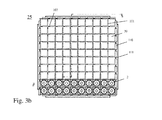
- the Fig. 3b shows the support structure 25 according to the Fig. 3a in a schematic plan view.
- the side walls 101 of the basic units serve as guide plates for the latching plates 107 of the basic units accommodated therein. Due to the interaction of the projections 108, 109 with the associated elongated holes 105, 106, the basic units are slidably mounted in the plane of the support structure 25. As a result of the interaction of the basic units, a plurality of substantially square or rectangular, elongated receptacles 39 are formed, into which the containers 2 can be introduced from above or from below.
- the basic units are spread apart so that the opening widths of the receptacles 39 allow unhindered insertion or at least an insertion of the container with little effort. Subsequently, all basic units can be so coordinated pressed against each other, that the recorded in the receptacles 39 container 2 finally fixed with sufficient force frictionally, in particular clamped. Also in this embodiment can be achieved that all bottoms of the container 2 are freely accessible from the bottom of the support structure 25 ago and are arranged together in a plane.
- the Fig. 3c shows the support structure 25 according to the Fig. 3b in a partial longitudinal section along the line AA according to the Fig. 3b ,
- the rectangular basic shape of the support structure 25 is accomplished in this embodiment by profile-shaped L-shaped elements 110 which are arranged on the outer walls of the outer base units, so that a substantially U-shaped receptacle is formed with a longitudinal slot in the base, in which which engages with a corresponding T-shaped profile locking rail 111 engages.
- a fixation of the position of all basic units 100 can be achieved, for example, by screwing or clamping the locking rail 111 at least to the foremost and rearmost basic units 100 a column or row of the matrix-shaped support structure 25th
- FIGS. 4a to 4e show a support structure 25 according to another embodiment.
- This is formed by a plurality of hexagonal receptacles 39 for receiving container 2, wherein the rows of hexagonal receptacles are arranged alternately offset from one another.
- the hexagonal receptacles 39 are formed by two pairs of at an obtuse angle to each other to running side walls 45, which are flexible Clamping webs 46 are interconnected.
- the flexible clamping webs 46 each have a concave holding portion 46a, wherein the connecting webs 47 are mirror-symmetrical, so that the concave indentations on the two sides of the clamping webs 46 face the side walls of the associated container 2.
- the support structure 25 can in principle be injection molded in one piece from a plastic.
- the holding structure 25 can also be composed of a plurality of honeycomb-shaped basic units, which are each produced individually and assembled in the illustrated arrangement and are held together in this arrangement by latching rails 49, as described below.
- the wavy webs 47 press the receptacles 39 of the support structure 25 in the illustration according to the Fig. 4a apart laterally, so that the clamping webs 46 with their indentations 46a in the in the Fig. 4c shown pressed against the side peripheral wall of the container 2, so that the container 2 are received with sufficient holding forces in the receptacles 39, as in the insert according to the Fig. 4b shown.
- L-shaped form-locking elements 48 are provided on the outer walls of the outermost hexagonal receptacles 39 in profile, which form T-shaped receptacles into which a correspondingly formed locking rail 49 is inserted.
- the receptacles 39 can be widened suitable.
- the in the Fig. 4d shown locking rails 49 can be hung in a side support frame or be supported on a support surface of a transport and packaging container.
- By upsetting the holding receptacles 39 can thus total of the opening widths of the receptacles 39 coordinated from the first position according to the Fig. 4c in the second position according to the Fig. 4b be transferred, in which the container 2 are fixed frictionally at predetermined positions.
- the altitude of the container 2 is determined due to the support of the bottoms of the container 2 on the webs 47 substantially by the webs 47.
- the sectional view according to the Fig. 4e can be removed, even in this embodiment, the largest part of the bottom of the container 2 from below freely accessible, for example, for a mechanical adjustment.
- the support structure is supported on the support surface formed by the step 13 near the upper edge, this can basically also be supported directly on the bottom 11 of the transport container 10. This basically works for all holding structures which have a certain axial length, be it that the bottoms of the containers 2 rest directly on the bottom 11 of the container 10 or on bottoms of the elongate receptacles 39 of the holding structure 25.
- the containers are arranged upright and with their open end towards the upper end of the transport and packaging container
- the containers can in principle also be turned, i. with its open end pointing to the bottom of the transport and packaging container, be arranged.
- a support structure 25 according to the present invention or even a transport and packaging container 1 according to the present invention may be covered by a sterile, gas-permeable protective film, which is glued and peeled off if necessary.
- a sterile, gas-permeable protective film which is glued and peeled off if necessary.
- the protective film may in particular be a gas-permeable plastic film, in particular a braid of synthetic fibers, for example of polypropylene fibers (PP) or even a Tyvek® protective film, which sterilizes the containers 2 accommodated and packed in the holding structure 25 through the film 130 therethrough.
- a gas-permeable plastic film in particular a braid of synthetic fibers, for example of polypropylene fibers (PP) or even a Tyvek® protective film, which sterilizes the containers 2 accommodated and packed in the holding structure 25 through the film 130 therethrough.
- antimicrobial powders may be added to the plastic of the support structure (of the carrier) and / or of the transport and packaging container.
- Antimicrobial acting powders with atoms or ions such as Ag, Zn, Cu, Ce, Te or I, are suitable as additives or fillers for a wide variety of purposes due to their biocidal, bacteriocidal, and fungicidal action.
- the biocidal effect occurs for example against bacilli, fungi, viruses, yeasts, algae and other microorganisms.
- biocidal powder can be added to the plastic of the support structure (the carrier) and / or the transport and packaging container in particular glass powder containing Ag 2 0, CuO, Cu 2 0, Te0 2 , ZnO, Ce0 2 and I.
- glass powder containing Ag 2 0, CuO, Cu 2 0, Te0 2 , ZnO, Ce0 2 and I.
- the mechanical and optical properties remain largely unchanged.
- the introduction of the powders can either be incorporated as nanopowders, for example, the plastic powder mixtures in injection molding or in paints in deep drawing processes.
- An antimicrobial effect can also be achieved if the plastic is provided with an antimicrobial coating containing the aforementioned powders.
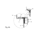
- FIGS. 6a and 6b show a further embodiment variant for a packaging unit 1 with a recorded in the transport and packaging container 10 holding plate 134, in which a plurality of containers 2 are fixed by means of ring elements 137 frictionally.
- the packaging unit 1 has provisions for identification and / or tracking as follows: As shown in the enlarged insert of FIG.
- an electronically wireless (wireless) readable RFID chip or RuBee chip 175 arranged (a RuBee chip sparks on frequencies that can penetrate metal and water), which can be read out without contact through the side walls of the packaging unit 1 and query information regarding the identity, important product characteristics (manufacturer, content, date of manufacture, expiration date, ...) etc. issues.
- the chip 175 may be glued into the packaging unit 1 at a suitable location, also elsewhere than shown in the figure.
- the chip 175 may be arranged so that in the case of opening the packaging unit 1 or removing the holding plate 134 from the packaging unit 1 out the chip 175 is destroyed, for example, is torn or disabled. Due to the lack of response of the chip 175 to a radio interrogation, information is thus available which indicates that the packaging unit has been manipulated in some way since the previous packaging must have been. Because the chip 175 does not respond to the radio query. This can serve, for example, to prove the authenticity and integrity of the packaging unit and the containers accommodated therein.
- luminescence plagiarism protection can be provided, specifically in the form of phosphors applied at a suitable location in or on the transport and packaging container, which are conventionally also referred to as "phosphors".
- the phosphors which are preferably invisible to the human eye, are characteristically distinguishable on the basis of different spectral emission spectra.
- the phosphors preferably consist of inorganic luminescence materials (eg microcrystals, nanocrystals and / or quantum dots) which fluoresce at certain wavelengths and / or phosphoresce.
- the different types of luminescence after the duration of illumination after the end of the excitation are divided into fluorescence ( ⁇ 1 msec) and phosphorescence ( ⁇ 1 msec).
- the emission wavelengths may have a narrow spectral width (eg, InBO 3 : Eu or Tb) and / or also broad emit (Ce: YAG).
- the spectral position depends on the composition and / or the concentration of the phosphors.
- the preparation is carried out by mixing the phosphors with plastic granules, powder, solvents and or paints before further processing (injection molding, deep drawing, ). Organic luminescent materials can also be used.
- the luminescent materials may, for example, be composed of different Eu doped materials such as CaS: Eu, Sr 2 Si 5 N 8 : Eu, SrS: Eu, Ba 2 Si 5 N 8 : Eu, Sr 2 SiO 4 : Eu, SrSi 2 N 2 O 2 : Eu, SrGa 2 S 4 : Eu, SrAl 2 O 4 : Eu, Ba 2 SiO 4 : Eu, Sr 4 Al 1 4 O 25 : Eu, SrSiAl 2 O 3 N: Eu, BaMgAl 10 O 17 : Eu, Sr 2 P 2 O 7 : Eu, SrB 4 O 7 : Eu, Y 2 O 3 : Eu, YAG: Eu, Ce: YAG: Eu, (Y, Gd) BO 3 : Eu, (Y, Gd) 2 O 3 : eu.
- Eu doped materials such as CaS: Eu, Sr 2 Si 5 N 8 : Eu, SrS: Eu, Ba 2 Si 5 N 8 : Eu,
- Luminescent materials can be co-doped or doped with other rare earths (scandium, yttrium, lanthanum, cerium, praseodymium, neodymium, promethium, samarium, gadolinium, terbium, dysprosium, holmium, erbium, thulium, ytterbium and lutetium) (eg LaPO 4 : Ce, Tb, LaMgAl 11 O 19 : Ce, Tb, (Y, Gd, Tb, Lu) AG: Ce, Lu 3-xz A x Al 5-yz Sc y O 12 : Mn z Ca z , Lu 2 SiO 5 : Ce, Gd 2 SiO 5 : Ce, Lu 1-xyab Y x Gd y ) 3 (Al 1-z Ga) 5 O 12 : Ce a Pr b ).
- rare earths eg LaPO 4 : Ce, Tb, LaMgAl
- LaPO 4 Pr, YPO 4 : Pr, (Ca, Mg) SO 4 : Pb, LuBO 3 : Pr, YBO 3 : Pr, Y 2 SiO 5 : Pr, SrSiO 3 : Pb, LaPO 4 : Ce, YPO 4 : Ce, LaMgAl 11 O 19 : Ce.
- the following luminescent materials may be used by way of example: InBO 3: Tb + InBO 3: Eu, ZnS: Ag, Y 2 O 2 S: Tb, Y 2 SiO 5: Tb, Y 3 (Al, Ga) 5 O 12 : Ce, (Zn, Cd) S: Cu, Cl + (Zn, Cd) S: Ag, Cl, Y 3 (Al, Ga) 5 O 12 : Tb, Zn 2 SiO 4 : Mn, Zn 8 BeSi 5 O 19 : Mn, CaWO 4 : W, Y 2 O 2 S: Eu + Fe 2 O 3, (Zn, Mg) F 2 : Mn, Y 3 Al 5 O 12 : Tb.
- the emission spectra of the fluorescent labels can be in the UV, visible spectral region (VIS) and / or in the infrared spectral region (NIR and / or MIR).
- the detection can be carried out with a commercially available spectrometer and / or time-resolved, for example with the aid of a Boxcarverlochrs to detect by means of detection in a time window, the temporal drop of the emission time resolved and / or at two different times at intervals and prove.
- the time interval can be, for example, from a few ns to a few ms and should be longer than the switch-off time of the light source.
- the luminescence markers can also be arranged in the form of 1D barcodes (eg EAN, UPC, IAN, JAN) and / or 2D barcodes (eg QR, Data Matrix, Maxi, dot) and / or as composite code.
- 1D barcodes eg EAN, UPC, IAN, JAN
- 2D barcodes eg QR, Data Matrix, Maxi, dot
- the barcodes can either be applied directly to the packaging by eg screen printing, ink jet printing or special stencil spraying or indirectly via labels (Plastic or paper) are glued.
- the application of several additive or structured luminescent layers is possible.
- the holding force exerted by the frictionally acting (clamping) holding means on the containers is sufficient to reliably hold the containers to the holding structure,
- the holding force exerted is greater than the weight of the containers, possibly with contents and sealing plugs
- the holding force can also be dimensioned by suitable design of the holding means so that it is greater than the usual force in the handling, processing or treatment of the containers in a process plant
- the force required for this purpose need only be greater than the force exerted by the holding means.
- the support structure in the context of the present invention also be formed of a thermoplastic, thermosetting or elastomeric plastic, at least portions of the support structure and the carrier are provided with a reibredumpden coating to facilitate the insertion and removal of the container ,
- the holding structure and / or the transport container, or portions thereof be formed of a fiber-reinforced plastics or a plastic, which are added to increase its thermal conductivity ceramics or metals added.
- fiber-reinforced plastics have a higher thermal conductivity of up to 0.9 W / (K m) for carbon fibers. If ceramics or metals are added to the plastics, the thermal conductivity is further increased. The result is the so-called thermally conductive plastics. This achieves a thermal conductivity of 20 W / (K m).
Landscapes
- Health & Medical Sciences (AREA)
- Life Sciences & Earth Sciences (AREA)
- Veterinary Medicine (AREA)
- Public Health (AREA)
- General Health & Medical Sciences (AREA)
- Animal Behavior & Ethology (AREA)
- Pharmacology & Pharmacy (AREA)
- Vascular Medicine (AREA)
- Heart & Thoracic Surgery (AREA)
- Hematology (AREA)
- Biomedical Technology (AREA)
- Anesthesiology (AREA)
- Engineering & Computer Science (AREA)
- Chemical Kinetics & Catalysis (AREA)
- Chemical & Material Sciences (AREA)
- Clinical Laboratory Science (AREA)
- Packages (AREA)
- Supplying Of Containers To The Packaging Station (AREA)
- Details Of Rigid Or Semi-Rigid Containers (AREA)
Applications Claiming Priority (2)
| Application Number | Priority Date | Filing Date | Title |
|---|---|---|---|
| US201261642142P | 2012-05-03 | 2012-05-03 | |
| DE102012103896A DE102012103896A1 (de) | 2012-05-03 | 2012-05-03 | Haltestruktur zum gleichzeitigen Halten einer Mehrzahl von medizinischen oder pharmazeutischen Behältern sowie Transport- oder Verpackungsbehälter mit Selbiger |
Publications (3)
| Publication Number | Publication Date |
|---|---|
| EP2659979A2 true EP2659979A2 (fr) | 2013-11-06 |
| EP2659979A3 EP2659979A3 (fr) | 2015-04-08 |
| EP2659979B1 EP2659979B1 (fr) | 2016-06-29 |
Family
ID=48236732
Family Applications (1)
| Application Number | Title | Priority Date | Filing Date |
|---|---|---|---|
| EP13166537.4A Active EP2659979B1 (fr) | 2012-05-03 | 2013-05-03 | Structure de support portant simultanément une pluralité de récipients pour des applications médicales, pharmaceutiques ou cosmétiques ainsi que récipient de transport ou d'emballage |
Country Status (3)
| Country | Link |
|---|---|
| US (1) | US20140027333A1 (fr) |
| EP (1) | EP2659979B1 (fr) |
| DE (1) | DE102012103896A1 (fr) |
Cited By (4)
| Publication number | Priority date | Publication date | Assignee | Title |
|---|---|---|---|---|
| EP2896406A3 (fr) * | 2013-12-27 | 2015-12-02 | Schott AG | Structure d'emballage et procédé d'emballage stérile de récipients pour des substances d'applications médicales, pharmaceutiques ou cosmétiques et procédé de traitement de récipients utilisant la structure d'emballage |
| WO2017139385A1 (fr) * | 2016-02-08 | 2017-08-17 | West Pharmaceutical Services, Inc. | Ensemble seringue emboîtable |
| DE102016121086A1 (de) * | 2016-11-04 | 2018-05-09 | Schott Schweiz Ag | Haltestruktur zum Halten einer Mehrzahl von Behältern für pharmazeutische, medizinische oder kosmetische Zwecke sowie Transport- oder Verpackungsbehälter mit selbiger |
| EP3700821A1 (fr) * | 2017-10-24 | 2020-09-02 | Schott AG | Procédé et dispositif de traitement flexible d'agents de conditionnement pharmaceutiques |
Families Citing this family (30)
| Publication number | Priority date | Publication date | Assignee | Title |
|---|---|---|---|---|
| JP5680375B2 (ja) * | 2010-11-05 | 2015-03-04 | 本田技研工業株式会社 | 切り出しパレット |
| EP2698624A1 (fr) * | 2012-08-16 | 2014-02-19 | Siemens Healthcare Diagnostics Products GmbH | Récipient réactionnel |
| US9220597B2 (en) * | 2013-02-12 | 2015-12-29 | Ossdsign Ab | Mosaic implants, kits and methods for correcting bone defects |
| CN105120802B (zh) | 2013-02-12 | 2018-01-12 | 奥斯设计公司 | 镶嵌型植入物、试剂盒和用于矫正骨缺损的方法 |
| US12515832B2 (en) | 2013-08-16 | 2026-01-06 | Vanrx Pharmasystems Inc. | Method, device and system for filling pharmaceutical containers |
| ES2718093T3 (es) * | 2013-08-16 | 2019-06-27 | Vanrx Pharmasystems Inc | Método para llenar envases farmacéuticos |
| DE102013114404A1 (de) * | 2013-12-18 | 2015-06-18 | Schott Ag | Transport- und Verpackungsbehälter mit einer Haltestruktur zum gleichzeitigen Halten einer Mehrzahl von Behältern für medizinische, pharmazeutische oder kosmetische Anwendungen sowie Verfahren und Verwendungen hiervon |
| BR112017002863A2 (pt) | 2014-08-14 | 2018-01-30 | Ossdsign Ab | implantes ósseos para correção de defeitos ósseos |
| JP6866287B2 (ja) * | 2014-08-15 | 2021-04-28 | サノフィ−アベンティス・ドイチュラント・ゲゼルシャフト・ミット・ベシュレンクテル・ハフツング | 注射デバイスおよび注射デバイスに取り付けるように構成された補助デバイス |
| DE102015116534A1 (de) * | 2015-07-23 | 2017-01-26 | Sig Technology Ag | Verfahren zum Sterilisieren von verpackten oder teilverpackten bzw. teilweise verschlossenen Gebrauchsgütern sowie dazu verwendbare Sammelbehälter und Umverpackungen |
| JP6929291B2 (ja) * | 2016-01-27 | 2021-09-01 | ウエスト ファーマスーティカル サービシーズ インコーポレイテッド | 六角チムニーを備えた中心オフセット付きのシリンジネスト |
| CA3039803A1 (fr) * | 2016-10-21 | 2018-04-26 | Genentech, Inc. | Dispositif d'administration de medicament heterogene scelle sterile |
| USD836797S1 (en) | 2017-04-04 | 2018-12-25 | West Pharmaceutical Services, Inc. | Medical container nest |
| USD835797S1 (en) | 2017-04-04 | 2018-12-11 | West Pharmaceutical Services, Inc. | Medical container nest |
| USD837400S1 (en) | 2017-04-04 | 2019-01-01 | West Pharmaceutical Services, Inc. | Medical container nest |
| USD835805S1 (en) | 2017-04-04 | 2018-12-11 | West Pharmaceutical Services, Inc. | Medical container nest |
| DE202018104076U1 (de) * | 2018-03-15 | 2018-07-23 | Leica Biosystems Nussloch Gmbh | Halter für einen Stapel von Deckgläsern und Deckglasstapelvorratshalter |
| US11358148B2 (en) * | 2018-03-30 | 2022-06-14 | Idexx Laboratories, Inc. | Point-of-care diagnostic systems and containers for same |
| DE102018111491A1 (de) * | 2018-05-14 | 2019-11-14 | Schott Schweiz Ag | Haltestruktur zum gleichzeitigen Halten einer Mehrzahl von Behältern für Substanzen für pharmazeutische, medizinische oder kosmetische Anwendungen, Transportgebilde und Transport- oder Verpackungsbehälter mit selbiger |
| JP7113855B2 (ja) * | 2018-07-16 | 2022-08-05 | ライカ ビオズュステムス ヌスロッホ ゲーエムベーハー | カバーガラスまたは試料支持体の積層体の収容ホルダ |
| WO2020142347A2 (fr) | 2018-12-31 | 2020-07-09 | Gen-Probe Incorporated | Systèmes et procédés de remplissage de cartouches à puits multiples avec des réactifs solides |
| US11273447B2 (en) * | 2019-01-11 | 2022-03-15 | Purdue Research Foundation | Collapsible basket arrays, collapsible cellular arrays therefor, and methods of use |
| EP3771656A1 (fr) * | 2019-07-30 | 2021-02-03 | SCHOTT Schweiz AG | Conditionnement de transport pour récipients et procédé de déballage de récipients |
| EP3848304B1 (fr) * | 2020-01-10 | 2024-03-13 | SCHOTT Pharma Schweiz AG | Dispositif de transport pour récipients médicaux |
| WO2021173603A1 (fr) * | 2020-02-24 | 2021-09-02 | Amgen Inc. | Récipients et systèmes destinés à être utilisés pendant la stérilisation externe de dispositifs d'administration de médicament |
| EP4186812A1 (fr) * | 2020-09-25 | 2023-05-31 | SCHOTT Pharma Schweiz AG | Agencement comprenant un dispositif de maintien et une pluralité de récipients avec une charge de particules après une simulation de transport |
| CN113682623A (zh) * | 2020-12-18 | 2021-11-23 | 蚌埠医学院 | 一种细菌检测用保存设备 |
| MX2022005952A (es) * | 2021-05-18 | 2023-04-10 | Gerresheimer Glas Gmbh | Transporte de unidades de envase. |
| EP4169545A1 (fr) | 2021-10-25 | 2023-04-26 | SCHOTT Pharma AG & Co. KGaA | Structure de support pour conteneurs prêts à l'emploi |
| BE1030359B1 (fr) | 2022-03-17 | 2023-10-16 | Aseptic Tech Sa | Système de manipulation de containers contenant une substance médicinale et un procédé de manipulation |
Citations (11)
| Publication number | Priority date | Publication date | Assignee | Title |
|---|---|---|---|---|
| US5950832A (en) | 1998-06-03 | 1999-09-14 | Brandeis University | Elastomeric sheet and support member for storing specimen vials |
| DE10012575A1 (de) | 2000-03-15 | 2001-09-27 | Schott Glas | Transportvorrichtung für medizinische Behälter |
| WO2009015862A1 (fr) | 2007-08-02 | 2009-02-05 | Semafra S.A. | Structure de conditionnement pour contenants en verre à usage pharmaceutique |
| WO2011015896A1 (fr) | 2009-08-07 | 2011-02-10 | Becton Dickinson France | Plateau de positionnement d'objets allongés, en particulier de corps de seringues ou de seringues |
| GB2478703A (en) | 2010-03-15 | 2011-09-21 | Agilent Technologies Inc | Trays with interleaved openings for the storage and transport of vials |
| WO2011135085A1 (fr) | 2010-04-30 | 2011-11-03 | Stevanato Group International A.S. | Structure de conditionnement pour récipients à usage pharmaceutique |
| US20110277419A1 (en) | 2009-01-27 | 2011-11-17 | Stevanato Group International A.S. | Packaging structure of containers for pharmaceutical use |
| WO2012007056A1 (fr) | 2010-07-16 | 2012-01-19 | Stevanato Group International A.S. | Processus de fabrication pour emballage de préparations injectables |
| US8100263B2 (en) | 2004-07-01 | 2012-01-24 | West Pharmaceutical Services, Inc. | Vacuum package system |
| US8118167B2 (en) | 2007-03-05 | 2012-02-21 | Daikyo Seiko, Ltd. | Medical container |
| WO2012025549A1 (fr) | 2010-08-27 | 2012-03-01 | Sanofi-Aventis Deutschland Gmbh | Système de conditionnement pour des produits médicaux à composants multiples |
Family Cites Families (18)
| Publication number | Priority date | Publication date | Assignee | Title |
|---|---|---|---|---|
| US1047366A (en) * | 1911-11-23 | 1912-12-17 | Nicholas F Alston | Whip-rack. |
| GB879397A (en) * | 1958-06-11 | 1961-10-11 | Etienne Jouet | Improvements in or relating to toy building blocks |
| US2979210A (en) * | 1960-04-19 | 1961-04-11 | Arthur H Thomas Company | Test tube rack |
| AU469958B2 (en) * | 1972-06-02 | 1976-02-26 | Tsurumi Soken | Cuboidal structure |
| US4495150A (en) * | 1983-07-25 | 1985-01-22 | Beckman Instruments, Inc. | Multiple object capturing and processing device |
| US4641755A (en) * | 1985-06-10 | 1987-02-10 | The United States Of America As Represented By The Secretary Of The Navy | Projectile stowage rack |
| GB2182018B (en) * | 1985-08-20 | 1989-04-12 | James Paul Tweddell | Improvements in frameworks |
| IT209233Z2 (it) * | 1985-10-14 | 1988-09-20 | Alfi Srl | Struttura di stativo per il supporto ed il contenimento di provette e simili. |
| DE3836163A1 (de) * | 1988-10-24 | 1990-04-26 | Berthold Lab Prof R | Aufnahmesystem fuer mehrere probengefaesse zur durchfuehrung von strahlungsmessungen |
| DE4021836C1 (fr) * | 1990-07-09 | 1991-05-02 | Arzneimittel Gmbh Apotheker Vetter & Co Ravensburg, 7980 Ravensburg, De | |
| US5169603A (en) * | 1991-08-01 | 1992-12-08 | David Landsberger | Modular test tube rack arrangement |
| US6132684A (en) * | 1997-10-31 | 2000-10-17 | Becton Dickinson And Company | Sample tube holder |
| US6390307B1 (en) * | 2001-05-18 | 2002-05-21 | Stan Stelter | Secure holding system for standards |
| US6640981B2 (en) * | 2001-08-14 | 2003-11-04 | 3088081 Canada Inc. | Modular test tube rack |
| DE10345625A1 (de) * | 2003-09-29 | 2005-04-28 | Schott Ag | Herstellungsverfahren eines Glaspulvers oder Glasproduktes mit antimikrobieller Wirkung |
| DE202006005652U1 (de) * | 2006-04-06 | 2006-06-14 | Schwaiger, Axel | Klappbarer Flaschenkasten |
| EP2219787B1 (fr) * | 2007-12-14 | 2018-08-01 | GE Healthcare Bio-Sciences AB | Cassette pour tubes à essais |
| GB201004102D0 (en) * | 2010-03-12 | 2010-04-28 | Liversidge Barry P | Syringe barrels and handling systems |
-
2012
- 2012-05-03 DE DE102012103896A patent/DE102012103896A1/de not_active Ceased
-
2013
- 2013-05-03 EP EP13166537.4A patent/EP2659979B1/fr active Active
- 2013-05-03 US US13/886,722 patent/US20140027333A1/en not_active Abandoned
Patent Citations (11)
| Publication number | Priority date | Publication date | Assignee | Title |
|---|---|---|---|---|
| US5950832A (en) | 1998-06-03 | 1999-09-14 | Brandeis University | Elastomeric sheet and support member for storing specimen vials |
| DE10012575A1 (de) | 2000-03-15 | 2001-09-27 | Schott Glas | Transportvorrichtung für medizinische Behälter |
| US8100263B2 (en) | 2004-07-01 | 2012-01-24 | West Pharmaceutical Services, Inc. | Vacuum package system |
| US8118167B2 (en) | 2007-03-05 | 2012-02-21 | Daikyo Seiko, Ltd. | Medical container |
| WO2009015862A1 (fr) | 2007-08-02 | 2009-02-05 | Semafra S.A. | Structure de conditionnement pour contenants en verre à usage pharmaceutique |
| US20110277419A1 (en) | 2009-01-27 | 2011-11-17 | Stevanato Group International A.S. | Packaging structure of containers for pharmaceutical use |
| WO2011015896A1 (fr) | 2009-08-07 | 2011-02-10 | Becton Dickinson France | Plateau de positionnement d'objets allongés, en particulier de corps de seringues ou de seringues |
| GB2478703A (en) | 2010-03-15 | 2011-09-21 | Agilent Technologies Inc | Trays with interleaved openings for the storage and transport of vials |
| WO2011135085A1 (fr) | 2010-04-30 | 2011-11-03 | Stevanato Group International A.S. | Structure de conditionnement pour récipients à usage pharmaceutique |
| WO2012007056A1 (fr) | 2010-07-16 | 2012-01-19 | Stevanato Group International A.S. | Processus de fabrication pour emballage de préparations injectables |
| WO2012025549A1 (fr) | 2010-08-27 | 2012-03-01 | Sanofi-Aventis Deutschland Gmbh | Système de conditionnement pour des produits médicaux à composants multiples |
Cited By (8)
| Publication number | Priority date | Publication date | Assignee | Title |
|---|---|---|---|---|
| EP2896406A3 (fr) * | 2013-12-27 | 2015-12-02 | Schott AG | Structure d'emballage et procédé d'emballage stérile de récipients pour des substances d'applications médicales, pharmaceutiques ou cosmétiques et procédé de traitement de récipients utilisant la structure d'emballage |
| US9598195B2 (en) | 2013-12-27 | 2017-03-21 | Schott Ag | Packaging structure and method for sterile packaging containers for substances for medical, pharmaceutical or cosmetic applications and methods for further processing of containers using this packaging structure |
| WO2017139385A1 (fr) * | 2016-02-08 | 2017-08-17 | West Pharmaceutical Services, Inc. | Ensemble seringue emboîtable |
| CN109069727A (zh) * | 2016-02-08 | 2018-12-21 | 西医药服务有限公司 | 注射器槽组件 |
| US11071817B2 (en) | 2016-02-08 | 2021-07-27 | West Pharmaceutical Services, Inc. | Syringe nest assembly |
| US11517661B2 (en) | 2016-02-08 | 2022-12-06 | West Pharmaceutical Services, Inc. | Syringe nest assembly |
| DE102016121086A1 (de) * | 2016-11-04 | 2018-05-09 | Schott Schweiz Ag | Haltestruktur zum Halten einer Mehrzahl von Behältern für pharmazeutische, medizinische oder kosmetische Zwecke sowie Transport- oder Verpackungsbehälter mit selbiger |
| EP3700821A1 (fr) * | 2017-10-24 | 2020-09-02 | Schott AG | Procédé et dispositif de traitement flexible d'agents de conditionnement pharmaceutiques |
Also Published As
| Publication number | Publication date |
|---|---|
| EP2659979B1 (fr) | 2016-06-29 |
| EP2659979A3 (fr) | 2015-04-08 |
| DE102012103896A1 (de) | 2013-11-07 |
| US20140027333A1 (en) | 2014-01-30 |
Similar Documents
| Publication | Publication Date | Title |
|---|---|---|
| EP2659979A2 (fr) | Structure de support pour le support simultané d'une pluralité de récipients pour des applications médicales, pharmaceutiques ou cosmétiques ainsi que récipient de transport ou d'emballage | |
| DE102013111600B4 (de) | Haltestruktur zum Halten von Behältern für Substanzen für medizinische, pharmazeutische oder kosmetische Anwendungen, sowie Transport- und Verpackungsbehälter mit selbiger | |
| DE102012103898A1 (de) | Haltestruktur zum gleichzeitigen Halten einer Mehrzahl von medizinischen oder pharmazeutischen Behältern sowie Transport- oder Verpackungsbehälter mit Selbiger | |
| DE102012103899B4 (de) | Verfahren und Vorrichtung zur Behandlung von Behältern zur Aufbewahrung von Substanzen für medizinische oder pharmazeutische Anwendungen | |
| DE102013112167A1 (de) | Haltestruktur zum gleichzeitigen Halten einer Mehrzahl von Behältern für Substanzen für medizinische, pharmazeutische oder kosmetische Anwendungen sowie Transport- und Verpackungsbehälter mit Selbiger sowie Verfahren | |
| DE102013114404A1 (de) | Transport- und Verpackungsbehälter mit einer Haltestruktur zum gleichzeitigen Halten einer Mehrzahl von Behältern für medizinische, pharmazeutische oder kosmetische Anwendungen sowie Verfahren und Verwendungen hiervon | |
| EP2659922B1 (fr) | Structure de support pour le support simultané d'une pluralité de récipients médicaux ou pharmaceutiques ainsi que récipient de transport ou d'emballage doté d'une telle structure | |
| EP2872843B1 (fr) | Structure de retenue permettant de retenir simultanément une pluralité de récipients pour des substances destinées à des applications médicales, pharmaceutiques ou cosmétiques, et récipients de transport ou d'emballage contenant lesdites substances | |
| EP2916885B1 (fr) | Dispositif et procédé destinés au traitement ou manipulation des récipients pour les substances pour les applications médicales, pharmaceutiques ou cosmétiques | |
| DE102013114896B4 (de) | Verpackungsstruktur und Verfahren zur sterilen Verpackung von Behältern für Substanzen für medizinische, pharmazeutische oder kosmetische Anwendungen sowie Verfahren zur Weiterverarbeitung von Behältern unter Verwendung der Verpackungsstruktur | |
| EP2531164B1 (fr) | Dispositif pour prélever un fluide dans un flacon | |
| DE102012110339B4 (de) | Haltestruktur zum gleichzeitigen Halten einer Mehrzahl von medizinischen oder pharmazeutischen Behältern sowie Transport- oder Verpackungsbehälter mit Selbiger und Verfahren zur Behandlung solcher Behälter | |
| EP2844936A2 (fr) | Procédé et dispositif pour manipuler des récipients et des substances contenues dans ces récipients pour des applications médicales, pharmaceutiques ou cosmétiques | |
| DE102012108215A1 (de) | Haltestruktur zum gleichzeitigen Halten einer Mehrzahl von Behältern für Substanzen für medizinische, pharmazeutische oder kosmetische Anwendungen sowie Transport- oder Verpackungsbehälter mit selbiger | |
| EP3254989B1 (fr) | Dispositif d'emballage pour des produits médicaux stérilisés ou à stériliser ayant une fixation interne | |
| DE102012110973B4 (de) | Verwendung eines Halteelements zum Halten eines Behälters, sowie Haltestruktur | |
| DE10012574A1 (de) | Spritze für medizinische Zwecke | |
| EP2659981B1 (fr) | Récipient de transport ou d'emballage avec structure de support pour le support simultané d'une pluralité de récipients pour des applications médicales, pharmaceutiques ou cosmétiques et procédé de traitement de tels récipients | |
| DE102007023198A1 (de) | Magazin für zylindrische Gefässe | |
| EP2662028A1 (fr) | Compresse et récipient destinés à la détection et au stockage stérile dýéchantillons biologiques |
Legal Events
| Date | Code | Title | Description |
|---|---|---|---|
| PUAI | Public reference made under article 153(3) epc to a published international application that has entered the european phase |
Free format text: ORIGINAL CODE: 0009012 |
|
| 17P | Request for examination filed |
Effective date: 20130503 |
|
| AK | Designated contracting states |
Kind code of ref document: A2 Designated state(s): AL AT BE BG CH CY CZ DE DK EE ES FI FR GB GR HR HU IE IS IT LI LT LU LV MC MK MT NL NO PL PT RO RS SE SI SK SM TR |
|
| AX | Request for extension of the european patent |
Extension state: BA ME |
|
| PUAL | Search report despatched |
Free format text: ORIGINAL CODE: 0009013 |
|
| AK | Designated contracting states |
Kind code of ref document: A3 Designated state(s): AL AT BE BG CH CY CZ DE DK EE ES FI FR GB GR HR HU IE IS IT LI LT LU LV MC MK MT NL NO PL PT RO RS SE SI SK SM TR |
|
| AX | Request for extension of the european patent |
Extension state: BA ME |
|
| RIC1 | Information provided on ipc code assigned before grant |
Ipc: B01L 9/06 20060101AFI20150303BHEP |
|
| RBV | Designated contracting states (corrected) |
Designated state(s): AL AT BE BG CH CY CZ DE DK EE ES FI FR GB GR HR HU IE IS IT LI LT LU LV MC MK MT NL NO PL PT RO RS SE SI SK SM TR |
|
| 17Q | First examination report despatched |
Effective date: 20150910 |
|
| GRAP | Despatch of communication of intention to grant a patent |
Free format text: ORIGINAL CODE: EPIDOSNIGR1 |
|
| INTG | Intention to grant announced |
Effective date: 20160309 |
|
| GRAS | Grant fee paid |
Free format text: ORIGINAL CODE: EPIDOSNIGR3 |
|
| GRAA | (expected) grant |
Free format text: ORIGINAL CODE: 0009210 |
|
| AK | Designated contracting states |
Kind code of ref document: B1 Designated state(s): AL AT BE BG CH CY CZ DE DK EE ES FI FR GB GR HR HU IE IS IT LI LT LU LV MC MK MT NL NO PL PT RO RS SE SI SK SM TR |
|
| REG | Reference to a national code |
Ref country code: GB Ref legal event code: FG4D Free format text: NOT ENGLISH |
|
| REG | Reference to a national code |
Ref country code: CH Ref legal event code: EP |
|
| REG | Reference to a national code |
Ref country code: AT Ref legal event code: REF Ref document number: 808652 Country of ref document: AT Kind code of ref document: T Effective date: 20160715 |
|
| REG | Reference to a national code |
Ref country code: IE Ref legal event code: FG4D Free format text: LANGUAGE OF EP DOCUMENT: GERMAN |
|
| REG | Reference to a national code |
Ref country code: DE Ref legal event code: R096 Ref document number: 502013003511 Country of ref document: DE |
|
| REG | Reference to a national code |
Ref country code: LT Ref legal event code: MG4D |
|
| PG25 | Lapsed in a contracting state [announced via postgrant information from national office to epo] |
Ref country code: NO Free format text: LAPSE BECAUSE OF FAILURE TO SUBMIT A TRANSLATION OF THE DESCRIPTION OR TO PAY THE FEE WITHIN THE PRESCRIBED TIME-LIMIT Effective date: 20160929 Ref country code: FI Free format text: LAPSE BECAUSE OF FAILURE TO SUBMIT A TRANSLATION OF THE DESCRIPTION OR TO PAY THE FEE WITHIN THE PRESCRIBED TIME-LIMIT Effective date: 20160629 Ref country code: LT Free format text: LAPSE BECAUSE OF FAILURE TO SUBMIT A TRANSLATION OF THE DESCRIPTION OR TO PAY THE FEE WITHIN THE PRESCRIBED TIME-LIMIT Effective date: 20160629 |
|
| REG | Reference to a national code |
Ref country code: NL Ref legal event code: MP Effective date: 20160629 |
|
| PG25 | Lapsed in a contracting state [announced via postgrant information from national office to epo] |
Ref country code: NL Free format text: LAPSE BECAUSE OF FAILURE TO SUBMIT A TRANSLATION OF THE DESCRIPTION OR TO PAY THE FEE WITHIN THE PRESCRIBED TIME-LIMIT Effective date: 20160629 Ref country code: RS Free format text: LAPSE BECAUSE OF FAILURE TO SUBMIT A TRANSLATION OF THE DESCRIPTION OR TO PAY THE FEE WITHIN THE PRESCRIBED TIME-LIMIT Effective date: 20160629 Ref country code: GR Free format text: LAPSE BECAUSE OF FAILURE TO SUBMIT A TRANSLATION OF THE DESCRIPTION OR TO PAY THE FEE WITHIN THE PRESCRIBED TIME-LIMIT Effective date: 20160930 Ref country code: LV Free format text: LAPSE BECAUSE OF FAILURE TO SUBMIT A TRANSLATION OF THE DESCRIPTION OR TO PAY THE FEE WITHIN THE PRESCRIBED TIME-LIMIT Effective date: 20160629 Ref country code: SE Free format text: LAPSE BECAUSE OF FAILURE TO SUBMIT A TRANSLATION OF THE DESCRIPTION OR TO PAY THE FEE WITHIN THE PRESCRIBED TIME-LIMIT Effective date: 20160629 Ref country code: HR Free format text: LAPSE BECAUSE OF FAILURE TO SUBMIT A TRANSLATION OF THE DESCRIPTION OR TO PAY THE FEE WITHIN THE PRESCRIBED TIME-LIMIT Effective date: 20160629 |
|
| PG25 | Lapsed in a contracting state [announced via postgrant information from national office to epo] |
Ref country code: RO Free format text: LAPSE BECAUSE OF FAILURE TO SUBMIT A TRANSLATION OF THE DESCRIPTION OR TO PAY THE FEE WITHIN THE PRESCRIBED TIME-LIMIT Effective date: 20160629 Ref country code: CZ Free format text: LAPSE BECAUSE OF FAILURE TO SUBMIT A TRANSLATION OF THE DESCRIPTION OR TO PAY THE FEE WITHIN THE PRESCRIBED TIME-LIMIT Effective date: 20160629 Ref country code: IS Free format text: LAPSE BECAUSE OF FAILURE TO SUBMIT A TRANSLATION OF THE DESCRIPTION OR TO PAY THE FEE WITHIN THE PRESCRIBED TIME-LIMIT Effective date: 20161029 Ref country code: EE Free format text: LAPSE BECAUSE OF FAILURE TO SUBMIT A TRANSLATION OF THE DESCRIPTION OR TO PAY THE FEE WITHIN THE PRESCRIBED TIME-LIMIT Effective date: 20160629 Ref country code: SK Free format text: LAPSE BECAUSE OF FAILURE TO SUBMIT A TRANSLATION OF THE DESCRIPTION OR TO PAY THE FEE WITHIN THE PRESCRIBED TIME-LIMIT Effective date: 20160629 |
|
| PG25 | Lapsed in a contracting state [announced via postgrant information from national office to epo] |
Ref country code: PT Free format text: LAPSE BECAUSE OF FAILURE TO SUBMIT A TRANSLATION OF THE DESCRIPTION OR TO PAY THE FEE WITHIN THE PRESCRIBED TIME-LIMIT Effective date: 20161031 Ref country code: SM Free format text: LAPSE BECAUSE OF FAILURE TO SUBMIT A TRANSLATION OF THE DESCRIPTION OR TO PAY THE FEE WITHIN THE PRESCRIBED TIME-LIMIT Effective date: 20160629 Ref country code: ES Free format text: LAPSE BECAUSE OF FAILURE TO SUBMIT A TRANSLATION OF THE DESCRIPTION OR TO PAY THE FEE WITHIN THE PRESCRIBED TIME-LIMIT Effective date: 20160629 Ref country code: PL Free format text: LAPSE BECAUSE OF FAILURE TO SUBMIT A TRANSLATION OF THE DESCRIPTION OR TO PAY THE FEE WITHIN THE PRESCRIBED TIME-LIMIT Effective date: 20160629 |
|
| REG | Reference to a national code |
Ref country code: DE Ref legal event code: R097 Ref document number: 502013003511 Country of ref document: DE |
|
| REG | Reference to a national code |
Ref country code: FR Ref legal event code: PLFP Year of fee payment: 5 |
|
| PG25 | Lapsed in a contracting state [announced via postgrant information from national office to epo] |
Ref country code: DK Free format text: LAPSE BECAUSE OF FAILURE TO SUBMIT A TRANSLATION OF THE DESCRIPTION OR TO PAY THE FEE WITHIN THE PRESCRIBED TIME-LIMIT Effective date: 20160629 |
|
| 26N | No opposition filed |
Effective date: 20170330 |
|
| PLBE | No opposition filed within time limit |
Free format text: ORIGINAL CODE: 0009261 |
|
| STAA | Information on the status of an ep patent application or granted ep patent |
Free format text: STATUS: NO OPPOSITION FILED WITHIN TIME LIMIT |
|
| PG25 | Lapsed in a contracting state [announced via postgrant information from national office to epo] |
Ref country code: BG Free format text: LAPSE BECAUSE OF FAILURE TO SUBMIT A TRANSLATION OF THE DESCRIPTION OR TO PAY THE FEE WITHIN THE PRESCRIBED TIME-LIMIT Effective date: 20160929 Ref country code: LU Free format text: LAPSE BECAUSE OF NON-PAYMENT OF DUE FEES Effective date: 20170531 Ref country code: SI Free format text: LAPSE BECAUSE OF FAILURE TO SUBMIT A TRANSLATION OF THE DESCRIPTION OR TO PAY THE FEE WITHIN THE PRESCRIBED TIME-LIMIT Effective date: 20160629 |
|
| GBPC | Gb: european patent ceased through non-payment of renewal fee |
Effective date: 20170503 |
|
| PG25 | Lapsed in a contracting state [announced via postgrant information from national office to epo] |
Ref country code: MC Free format text: LAPSE BECAUSE OF FAILURE TO SUBMIT A TRANSLATION OF THE DESCRIPTION OR TO PAY THE FEE WITHIN THE PRESCRIBED TIME-LIMIT Effective date: 20160629 |
|
| REG | Reference to a national code |
Ref country code: IE Ref legal event code: MM4A |
|
| PG25 | Lapsed in a contracting state [announced via postgrant information from national office to epo] |
Ref country code: LU Free format text: LAPSE BECAUSE OF NON-PAYMENT OF DUE FEES Effective date: 20170503 |
|
| PG25 | Lapsed in a contracting state [announced via postgrant information from national office to epo] |
Ref country code: GB Free format text: LAPSE BECAUSE OF NON-PAYMENT OF DUE FEES Effective date: 20170503 Ref country code: IE Free format text: LAPSE BECAUSE OF NON-PAYMENT OF DUE FEES Effective date: 20170503 |
|
| REG | Reference to a national code |
Ref country code: FR Ref legal event code: PLFP Year of fee payment: 6 |
|
| PG25 | Lapsed in a contracting state [announced via postgrant information from national office to epo] |
Ref country code: MT Free format text: LAPSE BECAUSE OF FAILURE TO SUBMIT A TRANSLATION OF THE DESCRIPTION OR TO PAY THE FEE WITHIN THE PRESCRIBED TIME-LIMIT Effective date: 20160629 |
|
| PG25 | Lapsed in a contracting state [announced via postgrant information from national office to epo] |
Ref country code: AL Free format text: LAPSE BECAUSE OF FAILURE TO SUBMIT A TRANSLATION OF THE DESCRIPTION OR TO PAY THE FEE WITHIN THE PRESCRIBED TIME-LIMIT Effective date: 20160629 |
|
| PG25 | Lapsed in a contracting state [announced via postgrant information from national office to epo] |
Ref country code: HU Free format text: LAPSE BECAUSE OF FAILURE TO SUBMIT A TRANSLATION OF THE DESCRIPTION OR TO PAY THE FEE WITHIN THE PRESCRIBED TIME-LIMIT; INVALID AB INITIO Effective date: 20130503 |
|
| REG | Reference to a national code |
Ref country code: AT Ref legal event code: MM01 Ref document number: 808652 Country of ref document: AT Kind code of ref document: T Effective date: 20180503 |
|
| PG25 | Lapsed in a contracting state [announced via postgrant information from national office to epo] |
Ref country code: CY Free format text: LAPSE BECAUSE OF NON-PAYMENT OF DUE FEES Effective date: 20160629 Ref country code: AT Free format text: LAPSE BECAUSE OF NON-PAYMENT OF DUE FEES Effective date: 20180503 |
|
| PG25 | Lapsed in a contracting state [announced via postgrant information from national office to epo] |
Ref country code: MK Free format text: LAPSE BECAUSE OF FAILURE TO SUBMIT A TRANSLATION OF THE DESCRIPTION OR TO PAY THE FEE WITHIN THE PRESCRIBED TIME-LIMIT Effective date: 20160629 |
|
| PG25 | Lapsed in a contracting state [announced via postgrant information from national office to epo] |
Ref country code: TR Free format text: LAPSE BECAUSE OF FAILURE TO SUBMIT A TRANSLATION OF THE DESCRIPTION OR TO PAY THE FEE WITHIN THE PRESCRIBED TIME-LIMIT Effective date: 20160629 |
|
| REG | Reference to a national code |
Ref country code: DE Ref legal event code: R081 Ref document number: 502013003511 Country of ref document: DE Owner name: SCHOTT PHARMA AG & CO. KGAA, DE Free format text: FORMER OWNER: SCHOTT AG, 55122 MAINZ, DE Ref country code: DE Ref legal event code: R082 Ref document number: 502013003511 Country of ref document: DE |
|
| REG | Reference to a national code |
Ref country code: BE Ref legal event code: PD Owner name: SCHOTT PHARMA AG & CO. KGAA; DE Free format text: DETAILS ASSIGNMENT: CHANGE OF OWNER(S), ASSIGNMENT; FORMER OWNER NAME: SCHOTT AG Effective date: 20221130 |
|
| P01 | Opt-out of the competence of the unified patent court (upc) registered |
Effective date: 20230516 |
|
| PGFP | Annual fee paid to national office [announced via postgrant information from national office to epo] |
Ref country code: DE Payment date: 20250521 Year of fee payment: 13 |
|
| PGFP | Annual fee paid to national office [announced via postgrant information from national office to epo] |
Ref country code: BE Payment date: 20250521 Year of fee payment: 13 Ref country code: IT Payment date: 20250527 Year of fee payment: 13 |
|
| PGFP | Annual fee paid to national office [announced via postgrant information from national office to epo] |
Ref country code: FR Payment date: 20250528 Year of fee payment: 13 |
|
| PGFP | Annual fee paid to national office [announced via postgrant information from national office to epo] |
Ref country code: CH Payment date: 20250601 Year of fee payment: 13 |