EP2659984B1 - Appareil d'extraction automatique de cellules utilisant une force magnétique et procédé d'extraction automatique de cellules l'utilisant - Google Patents
Appareil d'extraction automatique de cellules utilisant une force magnétique et procédé d'extraction automatique de cellules l'utilisant Download PDFInfo
- Publication number
- EP2659984B1 EP2659984B1 EP12176073.0A EP12176073A EP2659984B1 EP 2659984 B1 EP2659984 B1 EP 2659984B1 EP 12176073 A EP12176073 A EP 12176073A EP 2659984 B1 EP2659984 B1 EP 2659984B1
- Authority
- EP
- European Patent Office
- Prior art keywords
- cell
- magnetic field
- extracting
- self
- separation channel
- Prior art date
- Legal status (The legal status is an assumption and is not a legal conclusion. Google has not performed a legal analysis and makes no representation as to the accuracy of the status listed.)
- Not-in-force
Links
- 230000005291 magnetic effect Effects 0.000 title claims description 93
- 238000000034 method Methods 0.000 title claims description 15
- 238000000926 separation method Methods 0.000 claims description 70
- 239000012530 fluid Substances 0.000 claims description 37
- 239000000243 solution Substances 0.000 claims description 32
- 239000000758 substrate Substances 0.000 claims description 30
- 230000000903 blocking effect Effects 0.000 claims description 18
- 238000000605 extraction Methods 0.000 claims description 17
- 230000005294 ferromagnetic effect Effects 0.000 claims description 10
- 239000000284 extract Substances 0.000 claims description 6
- 239000002245 particle Substances 0.000 claims description 6
- 239000002952 polymeric resin Substances 0.000 claims description 4
- 229920003002 synthetic resin Polymers 0.000 claims description 4
- 238000007599 discharging Methods 0.000 claims description 3
- 239000011259 mixed solution Substances 0.000 claims description 2
- 210000004027 cell Anatomy 0.000 description 114
- 238000007792 addition Methods 0.000 description 10
- 238000004458 analytical method Methods 0.000 description 6
- 239000012528 membrane Substances 0.000 description 6
- 239000000463 material Substances 0.000 description 5
- 239000000654 additive Substances 0.000 description 4
- 230000000996 additive effect Effects 0.000 description 4
- 239000004205 dimethyl polysiloxane Substances 0.000 description 4
- 229920000435 poly(dimethylsiloxane) Polymers 0.000 description 4
- 229920003229 poly(methyl methacrylate) Polymers 0.000 description 4
- 239000004926 polymethyl methacrylate Substances 0.000 description 4
- 229920001343 polytetrafluoroethylene Polymers 0.000 description 4
- 230000008569 process Effects 0.000 description 4
- PXHVJJICTQNCMI-UHFFFAOYSA-N Nickel Chemical compound [Ni] PXHVJJICTQNCMI-UHFFFAOYSA-N 0.000 description 3
- 238000005516 engineering process Methods 0.000 description 3
- 238000002156 mixing Methods 0.000 description 3
- OKTJSMMVPCPJKN-UHFFFAOYSA-N Carbon Chemical compound [C] OKTJSMMVPCPJKN-UHFFFAOYSA-N 0.000 description 2
- 239000002041 carbon nanotube Substances 0.000 description 2
- 229910021393 carbon nanotube Inorganic materials 0.000 description 2
- 229920001577 copolymer Polymers 0.000 description 2
- 238000001471 micro-filtration Methods 0.000 description 2
- 238000012986 modification Methods 0.000 description 2
- 230000004048 modification Effects 0.000 description 2
- -1 polydimethylsiloxane Polymers 0.000 description 2
- 239000002861 polymer material Substances 0.000 description 2
- 239000011148 porous material Substances 0.000 description 2
- 238000006467 substitution reaction Methods 0.000 description 2
- 229920000049 Carbon (fiber) Polymers 0.000 description 1
- 208000005443 Circulating Neoplastic Cells Diseases 0.000 description 1
- XEEYBQQBJWHFJM-UHFFFAOYSA-N Iron Chemical compound [Fe] XEEYBQQBJWHFJM-UHFFFAOYSA-N 0.000 description 1
- 239000008280 blood Substances 0.000 description 1
- 210000004369 blood Anatomy 0.000 description 1
- 239000004917 carbon fiber Substances 0.000 description 1
- 238000003320 cell separation method Methods 0.000 description 1
- 230000008859 change Effects 0.000 description 1
- 239000010941 cobalt Substances 0.000 description 1
- 229910017052 cobalt Inorganic materials 0.000 description 1
- GUTLYIVDDKVIGB-UHFFFAOYSA-N cobalt atom Chemical compound [Co] GUTLYIVDDKVIGB-UHFFFAOYSA-N 0.000 description 1
- 239000000470 constituent Substances 0.000 description 1
- 239000003365 glass fiber Substances 0.000 description 1
- 230000005484 gravity Effects 0.000 description 1
- 230000010354 integration Effects 0.000 description 1
- 238000002032 lab-on-a-chip Methods 0.000 description 1
- 239000007788 liquid Substances 0.000 description 1
- 244000005700 microbiome Species 0.000 description 1
- 239000011859 microparticle Substances 0.000 description 1
- 239000000203 mixture Substances 0.000 description 1
- 239000002105 nanoparticle Substances 0.000 description 1
- 229910052759 nickel Inorganic materials 0.000 description 1
- 230000035699 permeability Effects 0.000 description 1
- 229920000052 poly(p-xylylene) Polymers 0.000 description 1
- 238000002360 preparation method Methods 0.000 description 1
- 102000004169 proteins and genes Human genes 0.000 description 1
- 108090000623 proteins and genes Proteins 0.000 description 1
- 238000000746 purification Methods 0.000 description 1
Images




Classifications
-
- B—PERFORMING OPERATIONS; TRANSPORTING
- B03—SEPARATION OF SOLID MATERIALS USING LIQUIDS OR USING PNEUMATIC TABLES OR JIGS; MAGNETIC OR ELECTROSTATIC SEPARATION OF SOLID MATERIALS FROM SOLID MATERIALS OR FLUIDS; SEPARATION BY HIGH-VOLTAGE ELECTRIC FIELDS
- B03C—MAGNETIC OR ELECTROSTATIC SEPARATION OF SOLID MATERIALS FROM SOLID MATERIALS OR FLUIDS; SEPARATION BY HIGH-VOLTAGE ELECTRIC FIELDS
- B03C1/00—Magnetic separation
- B03C1/02—Magnetic separation acting directly on the substance being separated
- B03C1/28—Magnetic plugs and dipsticks
- B03C1/288—Magnetic plugs and dipsticks disposed at the outer circumference of a recipient
-
- C—CHEMISTRY; METALLURGY
- C12—BIOCHEMISTRY; BEER; SPIRITS; WINE; VINEGAR; MICROBIOLOGY; ENZYMOLOGY; MUTATION OR GENETIC ENGINEERING
- C12M—APPARATUS FOR ENZYMOLOGY OR MICROBIOLOGY; APPARATUS FOR CULTURING MICROORGANISMS FOR PRODUCING BIOMASS, FOR GROWING CELLS OR FOR OBTAINING FERMENTATION OR METABOLIC PRODUCTS, i.e. BIOREACTORS OR FERMENTERS
- C12M1/00—Apparatus for enzymology or microbiology
- C12M1/42—Apparatus for the treatment of microorganisms or enzymes with electrical or wave energy, e.g. magnetism, sonic waves
-
- C—CHEMISTRY; METALLURGY
- C12—BIOCHEMISTRY; BEER; SPIRITS; WINE; VINEGAR; MICROBIOLOGY; ENZYMOLOGY; MUTATION OR GENETIC ENGINEERING
- C12N—MICROORGANISMS OR ENZYMES; COMPOSITIONS THEREOF; PROPAGATING, PRESERVING, OR MAINTAINING MICROORGANISMS; MUTATION OR GENETIC ENGINEERING; CULTURE MEDIA
- C12N13/00—Treatment of microorganisms or enzymes with electrical or wave energy, e.g. magnetism, sonic waves
-
- C—CHEMISTRY; METALLURGY
- C12—BIOCHEMISTRY; BEER; SPIRITS; WINE; VINEGAR; MICROBIOLOGY; ENZYMOLOGY; MUTATION OR GENETIC ENGINEERING
- C12Q—MEASURING OR TESTING PROCESSES INVOLVING ENZYMES, NUCLEIC ACIDS OR MICROORGANISMS; COMPOSITIONS OR TEST PAPERS THEREFOR; PROCESSES OF PREPARING SUCH COMPOSITIONS; CONDITION-RESPONSIVE CONTROL IN MICROBIOLOGICAL OR ENZYMOLOGICAL PROCESSES
- C12Q1/00—Measuring or testing processes involving enzymes, nucleic acids or microorganisms; Compositions therefor; Processes of preparing such compositions
- C12Q1/02—Measuring or testing processes involving enzymes, nucleic acids or microorganisms; Compositions therefor; Processes of preparing such compositions involving viable microorganisms
- C12Q1/24—Methods of sampling, or inoculating or spreading a sample; Methods of physically isolating an intact microorganisms
-
- B—PERFORMING OPERATIONS; TRANSPORTING
- B03—SEPARATION OF SOLID MATERIALS USING LIQUIDS OR USING PNEUMATIC TABLES OR JIGS; MAGNETIC OR ELECTROSTATIC SEPARATION OF SOLID MATERIALS FROM SOLID MATERIALS OR FLUIDS; SEPARATION BY HIGH-VOLTAGE ELECTRIC FIELDS
- B03C—MAGNETIC OR ELECTROSTATIC SEPARATION OF SOLID MATERIALS FROM SOLID MATERIALS OR FLUIDS; SEPARATION BY HIGH-VOLTAGE ELECTRIC FIELDS
- B03C2201/00—Details of magnetic or electrostatic separation
- B03C2201/26—Details of magnetic or electrostatic separation for use in medical or biological applications
Definitions
- the present invention relates to an apparatus for self-extracting a cell using a magnetic field, and a method using the same, and more particularly, to an apparatus for self-extracting a cell using a magnetic field to easily extract an effective cell from a cell solution, and a method using the same.
- cell-based diagnostics that are important in a biological or medical analysis are formed of blood analyses, cell studies, microorganism analyses and tissue transplant. Recently, unification and integration of processes of the cell-based diagnostics into a microfluidic device form have been studied in accordance with development of cell studies, cell analyses, and protein and DNA analysis technologies.
- the present invention has been made in an effort to provide an apparatus for self-extracting a cell using a magnetic field capable of selectively separating the cell using a separation channel and actively preventing an effective cell from blocking the separation channel by generating the magnetic field, and a method using the same.
- An exemplary embodiment of the present invention provides an apparatus for self-extracting a cell using a magnetic field to extract an effective cell that is a separation target from a cell solution, including: a flow path casing including an upper substrate and a lower substrate having a magnetic property combined with each other, and a fluid path formed to fluidize the cell solution therein; a separation portion disposed on the fluid path and provided with a separation channel selectively blocking the effective cell that is an extraction target in the cell included in the cell solution from passing therethrough; and a magnetic field control portion forming the magnetic field in the flow path portion to separate the effective cell blocking the separation channel from the separation channel.
- the separation channel may be constituted so that a width thereof becomes gradually narrow in a fluid direction of the cell solution.
- the separation portion may include a plurality of fine structures spaced apart from each other so that the width thereof becomes gradually wide in the fluid direction of the cell solution to form the separation channel.
- the plurality of fine structures may be constituted so that a gradient of the magnetic field generated between the magnetic field control portion and the lower substrate is increased.
- the lower substrate may be formed by curing a mixed solution of a polymer resin and a ferromagnetic particle.
- the magnetic field control portion may operate the magnetic field in the fluid path to perform controlling in the case where the separation channel is blocked by the effective cell.
- the magnetic field control portion may be constituted by an electromagnet to control an applied current, thereby controlling the intensity of the magnetic field.
- Another exemplary embodiment of the present invention provides a method for extracting a cell using a magnetic field, including: an addition step of adding a cell solution including an effective cell that is an extraction target and a non-effective cell that is a non-extraction target to a fluid path of a flow path casing; an extraction step of passing the cell solution through each of a plurality of separation channels to pass the non-effective cell therethrough and selectively extract the effective cell; and a magnetic field generation step of generating the magnetic field in the fluid path so as not to block the separation channel by the effective cell.
- the magnetic field may be generated while the addition step is performed to basically prevent the effective cell from blocking the separation channel.
- the magnetic field may be selectively generated to separate the effective cell blocking the separation channel from the separation channel.
- an apparatus for self-extracting a cell using a magnetic field to easily self-extract an effective cell that is a separation target using a separation channel magnetic field.
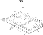
- FIG. 1 is a schematic perspective view of an apparatus for self-extracting a cell using a magnetic field according to an exemplary embodiment of the present invention
- FIG. 2 is a schematic exploded perspective view of the apparatus for self-extracting the cell using the magnetic field of FIG. 1
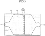
- FIG. 3 is a schematic top plan view of the apparatus for self-extracting the cell using the magnetic field of FIG. 1 , from which an upper substrate is removed
- FIG. 4 illustrates a cross-section of the apparatus for self-extracting the cell using the magnetic field of FIG. 1 , which is taken along the cut line IV - IV'.
- an apparatus 100 for self-extracting a cell using a magnetic field relates to an apparatus for extracting a cell which selectively self-extracts only an effective cell 20 from a cell solution including the effective cell 20 that is an extraction target and a non-effective cell 10 that is a non-extraction target, and includes a flow path casing 110, a separation portion 120 and a magnetic field control portion 130.
- a fluid path 114 for fluidizing the cell solution is formed in the flow path casing 110, and the flow path casing 110 includes an upper substrate 111, a side wall 112 and a lower substrate 113.
- the upper substrate 111 is combined with the side wall 112 and the lower substrate 113 to be described below so as to form the fluid path 114, and has a flat plate shape.
- PDMS polydimethylsiloxane
- PTFE polytetrafluroethylene
- PMMA polymethyl methacrylate
- COC cycloolefin copolymer
- the side wall 112 is interposed between the upper substrate 111 and the lower substrate 113 to be described below to connect both constituent elements to each other, and forms a space in the flow path casing 110 so as to provide the fluid path 114, an addition port 115 and a discharge port 116 therein.
- the side wall 112 constitutes a border between the upper substrate 111 and the lower substrate 113, and forms a space as the fluid path 114 therein.
- the fluid path 114 where a central region has the largest width and the width becomes narrow as going to both ends is formed in the side wall 112.
- the addition port 115 for adding the cell solution is formed at one end of the fluid path 114
- the discharge port 116 for discharging the non-effective cell 10 passing through the separation portion 120 to the outside is formed at the other end of the fluid path 114.
- the lower substrate 113 to be described below and the side wall 112 may be integrally formed of the same material in a single process, but may be separately manufactured through precision processing to be firmly attached to each other.
- the lower substrate 113 is integrally manufactured with the side wall 112 described above and the separation portion 120 to be described below to finish the fluid path 114 at the lower part thereof, and is formed to have the same flat plate shape as the upper substrate 111.
- the separation portion 120 is provided on the fluid path 114 in the flow path casing 110 to act as a filter for selectively extracting only the effective cell 20 that is the extraction target from the cell solution and act as a structure for increasing a gradient of the magnetic field generated from the magnetic field control portion 130 to be described below, and is constituted by a plurality of fine structures 121 and a separation channel 122 between the fine structures 121.
- the plurality of fine structures 121 are spaced apart from each other in a width direction of the fluid path 114 so as to form the separation channel 122, and each fine structure 121 has a shape where a width becomes gradually wide in a fluid direction (D) of the cell solution.
- the separation channel 122 formed in a space between the fine structures 121 where the width becomes gradually wide in the fluid direction (D) of the cell solution has a shape where a width becomes gradually narrow in the fluid direction (D) of the cell solution on the contrary to the shape of the fine structure 121.
- the width of the fine structure 121, the degree of change in width, the height and the like needs to be designed in overall consideration of a fluid speed of the cell solution, a kind of the cell solution, and a kind and a size of the effective cell 20 to be extracted.
- the fine structure 121 acts as a structure for increasing a gradient of the magnetic field generated between the magnetic field control portion 130 to be described below and the fine structure and it is necessary to determine a shape in consideration of the gradient of the magnetic field to be generated.
- the side wall 112, the lower substrate 113 and the separation portion 120 that are integrally formed are manufactured by curing a mixing material where ferromagnetic particles 118 are mixed with a liquid type polymer resin 117 so as to have a magnetic property.
- Nano or micro particles of nickel (Ni), cobalt (Co), iron (Fe) and the like may be used as the ferromagnetic particles 118 used in the present exemplary embodiment.
- polydimethylsiloxane (PDMS), polytetrafluroethylene (PTFE), polymethyl methacrylate (PMMA), cycloolefin copolymer (COC) and the like may be used as the polymer resin 117, but any general polymer material may be used without limitation.
- a separate non-ferromagnetic additive may be further included in the mixing material to improve characteristics such as strength, electric conductivity and thermal conductivity.
- Carbon nanotubes (CNT), carbon fibers, glass fibers or two or more thereof may be mixed and used while being mixed with each other as the non-ferromagnetic additive, and the non-ferromagnetic additive is not limited thereto as long as the non-ferromagnetic additive helps to improve the characteristics of the mixing material after curing.
- the fluid path where the addition port 115 and the discharge port 116 are formed at both ends is provided in the flow path casing, and since the lower substrate 113, the side wall 112 and the separation portion 120 include the uniformly distributed ferromagnetic particles 118, the magnetic property is ensured.
- the magnetic field control portion 130 is operated together with the lower substrate 113 and the ferromagnetic particles 118 in the fine structure 121 to generate the magnetic field in order to basically prevent the effective cell 20 that is the extraction target from blocking the separation channel 122 or selectively be operated only in the case where the effective cell 20 blocks the separation channel to prevent the blocking, and is provided at the lower part of the lower substrate 113.
- the magnetic field control portion 130 may be provided in an electromagnet form to control the intensity of magnetic property and operation, such that the intensity of total magnetic field may be controlled by controlling a quantity of applied current, but the form of the magnetic field control portion 130 is not limited thereto and the magnetic field control portion 130 may be provided in a permanent magnet form.
- An electromagnet may be provided, but a matter such as the permanent magnet which can generate the magnetic field may be used without limitation.
- FIGS. 5 and 6 illustrate an operation principle of separating an effective cell by the apparatus for self-extracting the cell using the magnetic field of FIG. 1 .
- the cell solution including the effective cell 20 that is the extraction target and the non-effective cell 10 that is not the extraction target is continuously added through the addition port 115 at the end of the fluid path 114.
- the cell solution added through the addition port 115 is continuously fluidized along the fluid path 114 and reaches the separation portion 120.
- the non-effective cell 10 having a diameter that is smaller than the width of the separation channel 122 passes through the separation channel 122 of the separation portion 120 and is discharged through the discharge port 116 at the end of the fluid path 114 to the outside.
- the effective cell having a diameter that is larger than the width of the separation channel 122 does not completely pass through the separation channel 122 but is extracted.
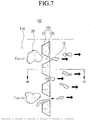
- FIG. 7 illustrates a principle of separating the effective cell blocking a separation channel in the apparatus for self-extracting the cell using the magnetic field of FIG. 1 .
- the magnetic field control portion 130 generates the magnetic field between the lower substrate 113 and the fine structure 121 while the cell solution is fluidized as described above, and the generated magnetic field is formed in the fluid path 114.
- the effective cell 20 may not block the separation channel 122 but be self-extracted by force (F cell) applied to the effective cell 20 from the magnetic field generated by the operation of the magnetic field control portion 130.
- F cell 1 2 ⁇ ⁇ ⁇ V cell ⁇ 0 ⁇
- F cell 1 2 ⁇ ⁇ ⁇ V cell ⁇ 0 ⁇
- Equation 1 the force (F cell ) applied to the effective cell 20 by the magnetic field generated from the magnetic field control portion 130 with the exception of gravity and fluidizing force by the cell solution may be represented by Equation 1.
- FIG. 8 illustrates a cross-section of the apparatus for self-extracting the cell using the magnetic field of FIG. 7 , which is taken along the cut line VIII-VIII'.
- the fine structure 121 having a shape protruding from the lower substrate 113 to the upper side functions to increase the gradient ( ⁇
- the effective cell 20 is basically prevented from blocking the separation channel 122 by operating the magnetic field control portion 130 during the extraction process of the cell solution, such that the effective cell 20 is self-extracted, but in another modified embodiment, the effective cell 20 blocking the separation channel 122 may be extracted from the separation channel 122 by selectively generating the magnetic field by the magnetic field control portion 130 only in the case where the effective cell 20 blocks the separation channel 122.
- the present invention it is possible to basically prevent the effective cell from blocking the separation channel and easily self-extract the effective cell by generating the magnetic field during the extraction operation or selectively generating the magnetic field.
Landscapes
- Chemical & Material Sciences (AREA)
- Life Sciences & Earth Sciences (AREA)
- Health & Medical Sciences (AREA)
- Engineering & Computer Science (AREA)
- Organic Chemistry (AREA)
- Wood Science & Technology (AREA)
- Bioinformatics & Cheminformatics (AREA)
- Zoology (AREA)
- Biotechnology (AREA)
- Genetics & Genomics (AREA)
- Microbiology (AREA)
- Biochemistry (AREA)
- General Engineering & Computer Science (AREA)
- General Health & Medical Sciences (AREA)
- Proteomics, Peptides & Aminoacids (AREA)
- Biomedical Technology (AREA)
- Medicinal Chemistry (AREA)
- Pathology (AREA)
- Physics & Mathematics (AREA)
- Analytical Chemistry (AREA)
- Biophysics (AREA)
- Sustainable Development (AREA)
- Immunology (AREA)
- Molecular Biology (AREA)
- Apparatus Associated With Microorganisms And Enzymes (AREA)
- Micro-Organisms Or Cultivation Processes Thereof (AREA)
Claims (11)
- Appareil (100) pour auto-extraction d'une cellule pour extraire une cellule efficace (20) qui est une cible de séparation d'une solution cellulaire,
comprenant :un boîtier de trajet d'écoulement (110) comportant un substrat supérieur (111) et un substrat inférieur (113) combinés entre eux, et un trajet de fluide (114) formé pour fluidifier la solution cellulaire dans celui-ci ;une partie de séparation (120) disposée sur le trajet de fluide (114) et pourvue d'un canal de séparation (122) empêchant sélectivement la cellule efficace (20) qui est une cible d'extraction dans la cellule incluse dans la solution cellulaire de passer à travers celui-ci ; et caractérisé en ce quele substrat supérieur (111) et le substrat inférieur (113) ont une propriété magnétique ; et en ce quel'appareil (100) comprend en outre une partie de commande de champ magnétique (130) formant un champ magnétique dans la partie de trajet d'écoulement pour séparer la cellule efficace (20) bloquant le canal de séparation (122) du canal de séparation (122). - Appareil (100) pour auto-extraction d'une cellule de la revendication 1, dans lequel :
le canal de séparation (122) est constitué de sorte que la largeur de celui-ci devienne progressivement étroite dans une direction de fluide de la solution cellulaire. - Appareil (100) pour auto-extraction d'une cellule de la revendication 2, dans lequel :
la partie de séparation (120) comporte une pluralité de structures fines (121) espacées les unes des autres de sorte que la largeur de celles-ci devienne progressivement grande dans la direction de fluide de la solution cellulaire pour former le canal de séparation (122). - Appareil (100) pour auto-extraction d'une cellule de la revendication 3, dans lequel :
la pluralité de structures fines (121) est constituée de sorte qu'un gradient du champ magnétique généré entre la partie de commande de champ magnétique (130) et le substrat inférieur (113) augmente. - Appareil (100) pour auto-extraction d'une cellule de la revendication 4, dans lequel :
un orifice d'ajout (115) pour ajouter la solution cellulaire et un orifice d'évacuation (116) pour évacuer une cellule non efficace (10) passant à travers la partie de séparation (120) vers l'extérieur sont formés aux deux extrémités du trajet de fluide (114). - Appareil (100) pour auto-extraction d'une cellule de la revendication 1, dans lequel :
le substrat inférieur (113) est formé par durcissement d'une solution mixte d'une résine polymère et d'une particule ferromagnétique. - Appareil (100) pour auto-extraction d'une cellule de la revendication 1, dans lequel :
la partie de commande de champ magnétique (130) active le champ magnétique dans le trajet de fluide (114) pour effectuer la commande dans le cas où le canal de séparation (122) est bloqué par la cellule efficace (20). - Appareil (100) pour auto-extraction d'une cellule de la revendication 1, dans lequel :
la partie de commande de champ magnétique (130) est constituée par un électroaimant pour commander un courant appliqué, commandant ainsi l'intensité du champ magnétique. - Procédé d'extraction d'une cellule en utilisant l'appareil (100) pour auto-extraction de la cellule de la revendication 1, comprenant :une étape d'ajout qui consiste à ajouter une solution cellulaire comportant une cellule efficace (20) qui est une cible d'extraction et une cellule non efficace (10) qui n'est pas une cible d'extraction au trajet de fluide (114) du boîtier de trajet d'écoulement ;une étape d'extraction qui consiste à faire passer la solution cellulaire à travers chacun d'une pluralité de canaux de séparation (122) pour faire passer la cellule non efficace (10) à travers ceux-ci et extraire sélectivement la cellule efficace (20) ; etune étape de génération de champ magnétique qui consiste à générer le champ magnétique dans le trajet de fluide (114) afin de ne pas bloquer le canal de séparation (122) par la cellule efficace (20).
- Procédé d'extraction d'une cellule de la revendication 9, dans lequel :
dans l'étape de génération de champ magnétique, le champ magnétique est généré pendant que l'étape d'ajout est effectuée pour empêcher essentiellement la cellule efficace (20) de bloquer le canal de séparation (122). - Procédé d'extraction d'une cellule de la revendication 9, dans lequel :
dans l'étape de génération de champ magnétique, le champ magnétique est sélectivement généré pour séparer la cellule efficace (20) bloquant le canal de séparation (122) du canal de séparation (122).
Applications Claiming Priority (1)
| Application Number | Priority Date | Filing Date | Title |
|---|---|---|---|
| KR1020120045751A KR101211862B1 (ko) | 2012-04-30 | 2012-04-30 | 자기장을 이용하는 자가 세포 추출장치 및 이를 이용하는 방법 |
Publications (3)
| Publication Number | Publication Date |
|---|---|
| EP2659984A2 EP2659984A2 (fr) | 2013-11-06 |
| EP2659984A3 EP2659984A3 (fr) | 2017-07-19 |
| EP2659984B1 true EP2659984B1 (fr) | 2018-11-14 |
Family
ID=46682647
Family Applications (1)
| Application Number | Title | Priority Date | Filing Date |
|---|---|---|---|
| EP12176073.0A Not-in-force EP2659984B1 (fr) | 2012-04-30 | 2012-07-12 | Appareil d'extraction automatique de cellules utilisant une force magnétique et procédé d'extraction automatique de cellules l'utilisant |
Country Status (4)
| Country | Link |
|---|---|
| US (1) | US9205432B2 (fr) |
| EP (1) | EP2659984B1 (fr) |
| JP (1) | JP5512754B2 (fr) |
| KR (1) | KR101211862B1 (fr) |
Families Citing this family (5)
| Publication number | Priority date | Publication date | Assignee | Title |
|---|---|---|---|---|
| US10406533B2 (en) * | 2015-06-24 | 2019-09-10 | Auburn University | Electromagnetic fluid filter using magnetostrictive sensors |
| KR102270402B1 (ko) | 2015-07-17 | 2021-06-29 | 주식회사 지노바이오 | 자기력 흐름을 이용한 MIP(Magnetic Iron Particles)분리장치 |
| KR101583017B1 (ko) | 2015-07-17 | 2016-01-06 | 주식회사 지노바이오 | MIP(Magnetic Iron Particles)분리 시스템 |
| KR101720609B1 (ko) | 2015-07-17 | 2017-03-28 | 주식회사 지노바이오 | 자기력 흐름을 이용한 MIP(Magnetic Iron Particles)분리장치 |
| KR101697457B1 (ko) * | 2016-03-30 | 2017-01-18 | 한국기계연구원 | 표적세포 포획용 필터장치 및 이를 이용한 표적세포 회수방법 |
Family Cites Families (15)
| Publication number | Priority date | Publication date | Assignee | Title |
|---|---|---|---|---|
| JPH0534337A (ja) | 1991-07-26 | 1993-02-09 | Terumo Corp | 白血球分離用フイルター |
| CA2134474C (fr) * | 1992-05-01 | 1999-07-06 | The Trustees Of The University Of Pennsylvania | Dispositif microfabrique de manutention d'echantillons de sperme |
| JP2004042012A (ja) | 2001-10-26 | 2004-02-12 | Nec Corp | 分離装置、分析システム、分離方法および分離装置の製造方法 |
| US20040018611A1 (en) * | 2002-07-23 | 2004-01-29 | Ward Michael Dennis | Microfluidic devices for high gradient magnetic separation |
| JP2005007352A (ja) | 2003-06-20 | 2005-01-13 | Sharp Corp | 粒子の分離方法及び分離装置並びに検出装置 |
| KR100624460B1 (ko) | 2005-02-12 | 2006-09-19 | 삼성전자주식회사 | 나노 내지 마이크로 크기의 포어가 형성되어 있는 막을 포함하는 미세유동장치 및 그를 이용하여 분극성 물질을 분리하는 방법 |
| KR100792185B1 (ko) | 2006-06-30 | 2008-01-07 | 재단법인서울대학교산학협력재단 | 자성 나노입자를 이용한 세포의 고정 또는 이동방법 |
| KR100872497B1 (ko) | 2007-03-27 | 2008-12-05 | 한국과학기술원 | 연속적 입자 분류기 |
| US20080302732A1 (en) * | 2007-05-24 | 2008-12-11 | Hyongsok Soh | Integrated fluidics devices with magnetic sorting |
| JP5231782B2 (ja) | 2007-10-26 | 2013-07-10 | 学校法人常翔学園 | 固液分離機能を有する装置及びその製造方法 |
| EP2238232B1 (fr) * | 2008-01-29 | 2019-08-14 | California Institute of Technology | Procédé et appareil de microfiltration pour effectuer une séparation de cellules |
| EP3586945A3 (fr) | 2009-06-05 | 2020-03-04 | IntegenX Inc. | Système universel de préparation d'échantillons et utilisation dans un système d'analyse intégré |
| PL2440941T3 (pl) | 2009-06-10 | 2017-10-31 | Cynvenio Biosystems Inc | Sposoby i urządzenia z przepływem laminarnym |
| KR20110041126A (ko) | 2009-10-15 | 2011-04-21 | 동우 화인켐 주식회사 | 포토레지스트 조성물 |
| KR101212030B1 (ko) * | 2012-04-30 | 2012-12-13 | 한국기계연구원 | 자성을 이용하는 세포분리장치 및 이를 이용하는 방법 |
-
2012
- 2012-04-30 KR KR1020120045751A patent/KR101211862B1/ko active Active
- 2012-07-11 US US13/546,187 patent/US9205432B2/en active Active
- 2012-07-11 JP JP2012155505A patent/JP5512754B2/ja active Active
- 2012-07-12 EP EP12176073.0A patent/EP2659984B1/fr not_active Not-in-force
Non-Patent Citations (1)
| Title |
|---|
| None * |
Also Published As
| Publication number | Publication date |
|---|---|
| EP2659984A3 (fr) | 2017-07-19 |
| JP2013230137A (ja) | 2013-11-14 |
| EP2659984A2 (fr) | 2013-11-06 |
| KR101211862B1 (ko) | 2012-12-12 |
| JP5512754B2 (ja) | 2014-06-04 |
| US9205432B2 (en) | 2015-12-08 |
| US20130284676A1 (en) | 2013-10-31 |
Similar Documents
| Publication | Publication Date | Title |
|---|---|---|
| US11833508B2 (en) | Multi-dimensional double spiral device and methods of use thereof | |
| Tang et al. | Recent advances in microfluidic cell sorting techniques based on both physical and biochemical principles | |
| KR101212030B1 (ko) | 자성을 이용하는 세포분리장치 및 이를 이용하는 방법 | |
| US9880084B2 (en) | Apparatus for separation of particles | |
| US9873126B2 (en) | Devices and methods for separating particles | |
| US10697871B2 (en) | Particle isolation/enrichment using continuous closed-loop micro-fluidics | |
| Chen et al. | Multiscale immunomagnetic enrichment of circulating tumor cells: from tubes to microchips | |
| CN110913988B (zh) | 使用致动的表面附接柱来处理细胞的系统、流体盒及方法 | |
| US20140034556A1 (en) | Apparatus and method for particle separation | |
| EP2659984B1 (fr) | Appareil d'extraction automatique de cellules utilisant une force magnétique et procédé d'extraction automatique de cellules l'utilisant | |
| Sun et al. | A magnetic nanoparticle assisted microfluidic system for low abundance cell sorting with high recovery | |
| KR100907213B1 (ko) | 등자기영동 기술을 이용한 미세입자 분리 장치 및등자기영동 기술을 이용한 미세입자 분리 방법 | |
| Zhou et al. | A microfluidic device for continuous-flow magnetically controlled capture and isolation of microparticles | |
| Bayareh et al. | Cancer cell separation using passive mechanisms: A review | |
| QIU et al. | Development of microfluidic device for cancer cell separation from blood using immunomagnetic beads | |
| Ohta et al. | Microdevices and Microsystems for Cell Manipulation | |
| Kumar | Inertio-and Elasto-Magnetic Fractionation of Multiple Microparticles in Newtonian and Non-Newtonian Fluid | |
| Aissa et al. | Label-free microfluidic blood cells micro-separator | |
| Lin | Automated microfluidic device for the separation of cancer cells from blood | |
| Samper et al. | Microfluidic sample preparation for nucleic acid analysis | |
| Sun et al. | A Magnetic Nanoparticle Assisted Microfluidic System for Low Abundance Cell |
Legal Events
| Date | Code | Title | Description |
|---|---|---|---|
| PUAI | Public reference made under article 153(3) epc to a published international application that has entered the european phase |
Free format text: ORIGINAL CODE: 0009012 |
|
| AK | Designated contracting states |
Kind code of ref document: A2 Designated state(s): AL AT BE BG CH CY CZ DE DK EE ES FI FR GB GR HR HU IE IS IT LI LT LU LV MC MK MT NL NO PL PT RO RS SE SI SK SM TR |
|
| AX | Request for extension of the european patent |
Extension state: BA ME |
|
| PUAL | Search report despatched |
Free format text: ORIGINAL CODE: 0009013 |
|
| AK | Designated contracting states |
Kind code of ref document: A3 Designated state(s): AL AT BE BG CH CY CZ DE DK EE ES FI FR GB GR HR HU IE IS IT LI LT LU LV MC MK MT NL NO PL PT RO RS SE SI SK SM TR |
|
| AX | Request for extension of the european patent |
Extension state: BA ME |
|
| RIC1 | Information provided on ipc code assigned before grant |
Ipc: G01N 33/483 20060101ALI20170613BHEP Ipc: B03C 1/28 20060101AFI20170613BHEP |
|
| STAA | Information on the status of an ep patent application or granted ep patent |
Free format text: STATUS: REQUEST FOR EXAMINATION WAS MADE |
|
| 17P | Request for examination filed |
Effective date: 20171219 |
|
| RBV | Designated contracting states (corrected) |
Designated state(s): AL AT BE BG CH CY CZ DE DK EE ES FI FR GB GR HR HU IE IS IT LI LT LU LV MC MK MT NL NO PL PT RO RS SE SI SK SM TR |
|
| GRAP | Despatch of communication of intention to grant a patent |
Free format text: ORIGINAL CODE: EPIDOSNIGR1 |
|
| STAA | Information on the status of an ep patent application or granted ep patent |
Free format text: STATUS: GRANT OF PATENT IS INTENDED |
|
| INTG | Intention to grant announced |
Effective date: 20180607 |
|
| GRAS | Grant fee paid |
Free format text: ORIGINAL CODE: EPIDOSNIGR3 |
|
| GRAA | (expected) grant |
Free format text: ORIGINAL CODE: 0009210 |
|
| STAA | Information on the status of an ep patent application or granted ep patent |
Free format text: STATUS: THE PATENT HAS BEEN GRANTED |
|
| AK | Designated contracting states |
Kind code of ref document: B1 Designated state(s): AL AT BE BG CH CY CZ DE DK EE ES FI FR GB GR HR HU IE IS IT LI LT LU LV MC MK MT NL NO PL PT RO RS SE SI SK SM TR |
|
| REG | Reference to a national code |
Ref country code: CH Ref legal event code: EP Ref country code: AT Ref legal event code: REF Ref document number: 1064193 Country of ref document: AT Kind code of ref document: T Effective date: 20181115 |
|
| REG | Reference to a national code |
Ref country code: DE Ref legal event code: R096 Ref document number: 602012053394 Country of ref document: DE |
|
| REG | Reference to a national code |
Ref country code: IE Ref legal event code: FG4D |
|
| REG | Reference to a national code |
Ref country code: NL Ref legal event code: MP Effective date: 20181114 |
|
| REG | Reference to a national code |
Ref country code: LT Ref legal event code: MG4D |
|
| REG | Reference to a national code |
Ref country code: AT Ref legal event code: MK05 Ref document number: 1064193 Country of ref document: AT Kind code of ref document: T Effective date: 20181114 |
|
| PG25 | Lapsed in a contracting state [announced via postgrant information from national office to epo] |
Ref country code: FI Free format text: LAPSE BECAUSE OF FAILURE TO SUBMIT A TRANSLATION OF THE DESCRIPTION OR TO PAY THE FEE WITHIN THE PRESCRIBED TIME-LIMIT Effective date: 20181114 Ref country code: IS Free format text: LAPSE BECAUSE OF FAILURE TO SUBMIT A TRANSLATION OF THE DESCRIPTION OR TO PAY THE FEE WITHIN THE PRESCRIBED TIME-LIMIT Effective date: 20190314 Ref country code: NO Free format text: LAPSE BECAUSE OF FAILURE TO SUBMIT A TRANSLATION OF THE DESCRIPTION OR TO PAY THE FEE WITHIN THE PRESCRIBED TIME-LIMIT Effective date: 20190214 Ref country code: AT Free format text: LAPSE BECAUSE OF FAILURE TO SUBMIT A TRANSLATION OF THE DESCRIPTION OR TO PAY THE FEE WITHIN THE PRESCRIBED TIME-LIMIT Effective date: 20181114 Ref country code: LV Free format text: LAPSE BECAUSE OF FAILURE TO SUBMIT A TRANSLATION OF THE DESCRIPTION OR TO PAY THE FEE WITHIN THE PRESCRIBED TIME-LIMIT Effective date: 20181114 Ref country code: ES Free format text: LAPSE BECAUSE OF FAILURE TO SUBMIT A TRANSLATION OF THE DESCRIPTION OR TO PAY THE FEE WITHIN THE PRESCRIBED TIME-LIMIT Effective date: 20181114 Ref country code: LT Free format text: LAPSE BECAUSE OF FAILURE TO SUBMIT A TRANSLATION OF THE DESCRIPTION OR TO PAY THE FEE WITHIN THE PRESCRIBED TIME-LIMIT Effective date: 20181114 Ref country code: BG Free format text: LAPSE BECAUSE OF FAILURE TO SUBMIT A TRANSLATION OF THE DESCRIPTION OR TO PAY THE FEE WITHIN THE PRESCRIBED TIME-LIMIT Effective date: 20190214 Ref country code: HR Free format text: LAPSE BECAUSE OF FAILURE TO SUBMIT A TRANSLATION OF THE DESCRIPTION OR TO PAY THE FEE WITHIN THE PRESCRIBED TIME-LIMIT Effective date: 20181114 |
|
| PG25 | Lapsed in a contracting state [announced via postgrant information from national office to epo] |
Ref country code: AL Free format text: LAPSE BECAUSE OF FAILURE TO SUBMIT A TRANSLATION OF THE DESCRIPTION OR TO PAY THE FEE WITHIN THE PRESCRIBED TIME-LIMIT Effective date: 20181114 Ref country code: PT Free format text: LAPSE BECAUSE OF FAILURE TO SUBMIT A TRANSLATION OF THE DESCRIPTION OR TO PAY THE FEE WITHIN THE PRESCRIBED TIME-LIMIT Effective date: 20190314 Ref country code: SE Free format text: LAPSE BECAUSE OF FAILURE TO SUBMIT A TRANSLATION OF THE DESCRIPTION OR TO PAY THE FEE WITHIN THE PRESCRIBED TIME-LIMIT Effective date: 20181114 Ref country code: NL Free format text: LAPSE BECAUSE OF FAILURE TO SUBMIT A TRANSLATION OF THE DESCRIPTION OR TO PAY THE FEE WITHIN THE PRESCRIBED TIME-LIMIT Effective date: 20181114 Ref country code: RS Free format text: LAPSE BECAUSE OF FAILURE TO SUBMIT A TRANSLATION OF THE DESCRIPTION OR TO PAY THE FEE WITHIN THE PRESCRIBED TIME-LIMIT Effective date: 20181114 Ref country code: GR Free format text: LAPSE BECAUSE OF FAILURE TO SUBMIT A TRANSLATION OF THE DESCRIPTION OR TO PAY THE FEE WITHIN THE PRESCRIBED TIME-LIMIT Effective date: 20190215 |
|
| PG25 | Lapsed in a contracting state [announced via postgrant information from national office to epo] |
Ref country code: CZ Free format text: LAPSE BECAUSE OF FAILURE TO SUBMIT A TRANSLATION OF THE DESCRIPTION OR TO PAY THE FEE WITHIN THE PRESCRIBED TIME-LIMIT Effective date: 20181114 Ref country code: PL Free format text: LAPSE BECAUSE OF FAILURE TO SUBMIT A TRANSLATION OF THE DESCRIPTION OR TO PAY THE FEE WITHIN THE PRESCRIBED TIME-LIMIT Effective date: 20181114 Ref country code: DK Free format text: LAPSE BECAUSE OF FAILURE TO SUBMIT A TRANSLATION OF THE DESCRIPTION OR TO PAY THE FEE WITHIN THE PRESCRIBED TIME-LIMIT Effective date: 20181114 Ref country code: IT Free format text: LAPSE BECAUSE OF FAILURE TO SUBMIT A TRANSLATION OF THE DESCRIPTION OR TO PAY THE FEE WITHIN THE PRESCRIBED TIME-LIMIT Effective date: 20181114 |
|
| REG | Reference to a national code |
Ref country code: DE Ref legal event code: R097 Ref document number: 602012053394 Country of ref document: DE |
|
| PG25 | Lapsed in a contracting state [announced via postgrant information from national office to epo] |
Ref country code: EE Free format text: LAPSE BECAUSE OF FAILURE TO SUBMIT A TRANSLATION OF THE DESCRIPTION OR TO PAY THE FEE WITHIN THE PRESCRIBED TIME-LIMIT Effective date: 20181114 Ref country code: SM Free format text: LAPSE BECAUSE OF FAILURE TO SUBMIT A TRANSLATION OF THE DESCRIPTION OR TO PAY THE FEE WITHIN THE PRESCRIBED TIME-LIMIT Effective date: 20181114 Ref country code: RO Free format text: LAPSE BECAUSE OF FAILURE TO SUBMIT A TRANSLATION OF THE DESCRIPTION OR TO PAY THE FEE WITHIN THE PRESCRIBED TIME-LIMIT Effective date: 20181114 Ref country code: SK Free format text: LAPSE BECAUSE OF FAILURE TO SUBMIT A TRANSLATION OF THE DESCRIPTION OR TO PAY THE FEE WITHIN THE PRESCRIBED TIME-LIMIT Effective date: 20181114 |
|
| PLBE | No opposition filed within time limit |
Free format text: ORIGINAL CODE: 0009261 |
|
| STAA | Information on the status of an ep patent application or granted ep patent |
Free format text: STATUS: NO OPPOSITION FILED WITHIN TIME LIMIT |
|
| 26N | No opposition filed |
Effective date: 20190815 |
|
| PG25 | Lapsed in a contracting state [announced via postgrant information from national office to epo] |
Ref country code: SI Free format text: LAPSE BECAUSE OF FAILURE TO SUBMIT A TRANSLATION OF THE DESCRIPTION OR TO PAY THE FEE WITHIN THE PRESCRIBED TIME-LIMIT Effective date: 20181114 |
|
| PG25 | Lapsed in a contracting state [announced via postgrant information from national office to epo] |
Ref country code: MC Free format text: LAPSE BECAUSE OF FAILURE TO SUBMIT A TRANSLATION OF THE DESCRIPTION OR TO PAY THE FEE WITHIN THE PRESCRIBED TIME-LIMIT Effective date: 20181114 |
|
| REG | Reference to a national code |
Ref country code: CH Ref legal event code: PL |
|
| PG25 | Lapsed in a contracting state [announced via postgrant information from national office to epo] |
Ref country code: TR Free format text: LAPSE BECAUSE OF FAILURE TO SUBMIT A TRANSLATION OF THE DESCRIPTION OR TO PAY THE FEE WITHIN THE PRESCRIBED TIME-LIMIT Effective date: 20181114 |
|
| REG | Reference to a national code |
Ref country code: BE Ref legal event code: MM Effective date: 20190731 |
|
| PG25 | Lapsed in a contracting state [announced via postgrant information from national office to epo] |
Ref country code: BE Free format text: LAPSE BECAUSE OF NON-PAYMENT OF DUE FEES Effective date: 20190731 Ref country code: CH Free format text: LAPSE BECAUSE OF NON-PAYMENT OF DUE FEES Effective date: 20190731 Ref country code: LU Free format text: LAPSE BECAUSE OF NON-PAYMENT OF DUE FEES Effective date: 20190712 Ref country code: LI Free format text: LAPSE BECAUSE OF NON-PAYMENT OF DUE FEES Effective date: 20190731 |
|
| PG25 | Lapsed in a contracting state [announced via postgrant information from national office to epo] |
Ref country code: IE Free format text: LAPSE BECAUSE OF NON-PAYMENT OF DUE FEES Effective date: 20190712 |
|
| PG25 | Lapsed in a contracting state [announced via postgrant information from national office to epo] |
Ref country code: CY Free format text: LAPSE BECAUSE OF FAILURE TO SUBMIT A TRANSLATION OF THE DESCRIPTION OR TO PAY THE FEE WITHIN THE PRESCRIBED TIME-LIMIT Effective date: 20181114 |
|
| PG25 | Lapsed in a contracting state [announced via postgrant information from national office to epo] |
Ref country code: HU Free format text: LAPSE BECAUSE OF FAILURE TO SUBMIT A TRANSLATION OF THE DESCRIPTION OR TO PAY THE FEE WITHIN THE PRESCRIBED TIME-LIMIT; INVALID AB INITIO Effective date: 20120712 Ref country code: MT Free format text: LAPSE BECAUSE OF FAILURE TO SUBMIT A TRANSLATION OF THE DESCRIPTION OR TO PAY THE FEE WITHIN THE PRESCRIBED TIME-LIMIT Effective date: 20181114 |
|
| PG25 | Lapsed in a contracting state [announced via postgrant information from national office to epo] |
Ref country code: MK Free format text: LAPSE BECAUSE OF FAILURE TO SUBMIT A TRANSLATION OF THE DESCRIPTION OR TO PAY THE FEE WITHIN THE PRESCRIBED TIME-LIMIT Effective date: 20181114 |
|
| PGFP | Annual fee paid to national office [announced via postgrant information from national office to epo] |
Ref country code: GB Payment date: 20220606 Year of fee payment: 11 |
|
| PGFP | Annual fee paid to national office [announced via postgrant information from national office to epo] |
Ref country code: FR Payment date: 20220609 Year of fee payment: 11 |
|
| PGFP | Annual fee paid to national office [announced via postgrant information from national office to epo] |
Ref country code: DE Payment date: 20220531 Year of fee payment: 11 |
|
| REG | Reference to a national code |
Ref country code: DE Ref legal event code: R119 Ref document number: 602012053394 Country of ref document: DE |
|
| GBPC | Gb: european patent ceased through non-payment of renewal fee |
Effective date: 20230712 |
|
| PG25 | Lapsed in a contracting state [announced via postgrant information from national office to epo] |
Ref country code: DE Free format text: LAPSE BECAUSE OF NON-PAYMENT OF DUE FEES Effective date: 20240201 Ref country code: GB Free format text: LAPSE BECAUSE OF NON-PAYMENT OF DUE FEES Effective date: 20230712 |
|
| PG25 | Lapsed in a contracting state [announced via postgrant information from national office to epo] |
Ref country code: FR Free format text: LAPSE BECAUSE OF NON-PAYMENT OF DUE FEES Effective date: 20230731 |