EP2660102A1 - Équipement pour récupérer des véhicules en panne et système muni d'un tel équipement - Google Patents
Équipement pour récupérer des véhicules en panne et système muni d'un tel équipement Download PDFInfo
- Publication number
- EP2660102A1 EP2660102A1 EP12425083.8A EP12425083A EP2660102A1 EP 2660102 A1 EP2660102 A1 EP 2660102A1 EP 12425083 A EP12425083 A EP 12425083A EP 2660102 A1 EP2660102 A1 EP 2660102A1
- Authority
- EP
- European Patent Office
- Prior art keywords
- equipment
- bar
- movable body
- longitudinal
- broken
- Prior art date
- Legal status (The legal status is an assumption and is not a legal conclusion. Google has not performed a legal analysis and makes no representation as to the accuracy of the status listed.)
- Granted
Links
- 238000006073 displacement reaction Methods 0.000 claims abstract description 4
- 239000012530 fluid Substances 0.000 description 2
- 230000010355 oscillation Effects 0.000 description 2
- 230000015556 catabolic process Effects 0.000 description 1
- 238000010276 construction Methods 0.000 description 1
- 238000011084 recovery Methods 0.000 description 1
Images


Classifications
-
- B—PERFORMING OPERATIONS; TRANSPORTING
- B60—VEHICLES IN GENERAL
- B60P—VEHICLES ADAPTED FOR LOAD TRANSPORTATION OR TO TRANSPORT, TO CARRY, OR TO COMPRISE SPECIAL LOADS OR OBJECTS
- B60P3/00—Vehicles adapted to transport, to carry or to comprise special loads or objects
- B60P3/12—Vehicles adapted to transport, to carry or to comprise special loads or objects for salvaging damaged vehicles
- B60P3/125—Vehicles adapted to transport, to carry or to comprise special loads or objects for salvaging damaged vehicles by supporting only part of the vehicle, e.g. front- or rear-axle
Definitions
- the present invention relates to an equipment and a system in particular for recovering broken-down vehicles.
- a system of the kind mentioned above which is capable of reducing the bulk of the help vehicle on which the system is mounted.
- System 10 is intended to be mounted on the frame of a help vehicle, such as for instance a breakdown truck, for instance at the end of such a frame.
- a help vehicle such as for instance a breakdown truck
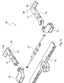
- system 10 includes an equipment or fork assembly 36 associated with a movable body 14 and arranged to lift a pair of wheels, mounted on a same axle, of a broken-down vehicle.
- Movable body 14 of known type, can be associated with a fixed support structure, mounted for instance on the vehicle frame.
- movable body 14 mainly extends in longitudinal direction.
- System 10 preferably includes a longitudinal extendable device 20 connected to movable body 14 and arranged to be extended in controlled way from a retracted condition to an extended condition in a longitudinal direction or axis X - X relative to movable body 14.
- Longitudinal extendable device 20 acts as an appendage allowing longitudinally extending movable body 14 depending on the operating needs.
- longitudinal extendable device 20 is a telescopic device and includes, for instance, a first tubular element 22 and a second tubular element 24 arranged to slide inside each other.
- movable body 14 has a longitudinal portion 26.
- longitudinal portion 26 is hollow and longitudinal extendable device 20, for instance, tubular elements 22, 24 thereof, is arranged to slide inside it.
- longitudinal extendable device 20 includes an actuating member of a kind known to the skilled in the art and capable of driving the displacement of tubular elements 22, 24 through longitudinal portion 26.
- the actuating member provides for an actuation by a linear actuator, for instance a fluid driven double-effect cylinder.
- system 10 preferably further includes a transverse appendage, not shown in the drawing, integral for rotation with movable body 14, in such a way as to allow the oscillation of movable body 14 in correspondence of lateral oscillation axis Y - Y.
- the equipment or fork assembly 36 associated with movable body 14 is arranged to lift a pair of wheels, mounted on a same axle, both of vehicles with a single-wheel axle and of vehicles with twin-wheel axle.
- fork assembly 36 is connected with movable body 14 via longitudinal extendable device 20.
- fork assembly 36 is rotatably mounted, for instance pivotally connected through a pivot pin 45, relative to longitudinal extendable device 20, so as to rotate about a transverse yaw axis Z-Z ( Fig. 1 ), substantially transversal to longitudinal sliding axis X-X of longitudinal extendable device 20.
- fork assembly 36 is mounted in correspondence of the second tubular element 24.
- fork assembly 36 has substantially a yoke-like shape defined by a bar 37 oriented in lateral direction, on which two slides 43 are slidably mounted in adjustable manner.
- bar 37 includes an actuating member of a kind known to the skilled in the art, which is connected to slides 43 and is capable of driving their displacement.
- the actuating member provides for an actuation by a linear actuator 44, for instance a fluid driven double-effect cylinder, of which a first end is connected to one slide 43 and the other end is connected to the second slide.
- bar 37 is connected with movable body 14 via longitudinal extendable device 20.
- bar 37 is rotatably mounted, for instance is pivotally connected through a pivot pin 45, relative to longitudinal extendable device 20, so as to rotate about transverse yaw axis Z - Z ( Fig. 1 )
- Two arms 38 are associated with bar 37. They are preferably connected to bar 37 via slides 43 and are arranged to cooperate with the bar in order to lift a pair of wheels, mounted on the same axle, of a broken-down vehicle.
- each arm 38 is rotatably mounted on the respective slide 43, for instance the arms are pivotally connected to the slide by means of a hinge 51.
- Each arm is arranged to rotate about a respective transverse axis Z1-Z1 and Z2-Z2, substantially transversal to the axis of bar 37 and to longitudinal sliding axis X-X of longitudinal extendable device 20.
- hinge 51 is located at one end of arm 38.
- Arms 38 are arranged to rotate between a first, travelling position of the fork assembly ( Fig. 2a ), in which they are oriented in lateral direction, parallel to bar 37 and preferably in contact therewith and7or with slides 43, and a second, operating position of the fork assembly ( Figs. 1 and 2d ), in which they are oriented in longitudinal direction.
- Each arm 38 has a respective outward projecting lateral extension 39 arranged to be placed under the wheel to be lifted, and a plurality of lateral seats 40 and upper seats 41, for instance holes.
- Lateral seats 40 are arranged to house known pulleys for towing the broken-down vehicle by means of a rope and a winch of known type, whereas upper seats 41 are arranged to house rotatable or orientable forks, also of known type, in order to lift the axle of the broken-down vehicle.
- lateral extensions 39, arms 38, bar 37 and slides 43 define respective housings for the wheels of the broken-down vehicle to be lifted, and the position of arms 38 is adjusted, by displacing slides 43 to which arms 38 are hinged, depending on the distance between the wheels of the axle to be lifted of the said broken-down vehicle, so as to allow the arms to pass between the wheels.
- lateral extensions 39 are positioned under the wheel to be lifted ( Fig. 2d ) and they cooperate with arms 38, bar 37 and slides 43 in order to lift a pair of wheels, mounted on a same axle, of a broken-down vehicle.
- slides 43 are positioned in the central portion of bar 37 and are adjusted so as to bring lateral extensions 39 and arms 38 in contact with bar 37 and slides 43, so as to minimise the bulk of fork assembly 36.
- arms 38 are brought in contact with bar 37 by an outward rotation, and they are equipped with a stop member in order to be locked in the operating position.
- lateral extensions 39 and the ends of bar 37 are so shaped as to allow them to be superimposed when fork assembly 36 is in the travelling position or to be inserted into one another.
- lateral extensions 39 have a surface with the same inclination as that of the profile of the ends of bar 37 ( Fig. 1 ).
- system 10 includes, for instance on the end of longitudinal portion 26 of movable body 14, a pair of wings 46 ( Fig. 1 ) projecting from two laterally opposite sides, and lifting actuators are hinged in correspondence of said wings.
- Each lifting actuator is hinged on the one side to the support structure and on the other side to movable body 14. Moreover, each lifting actuator is arranged to control the angular position of movable body 14 with respect to the support structure, for instance about lateral axis Y-Y.
- fork assembly 36 is in travelling position and, in order to be able to intervene on the broken-down vehicle, system 10 is brought to a lowered arrangement.
- movable body 14 together with fork assembly 36 is for instance overturned about axis Y-Y so as to be located near the road surface, in order to be able to pass under the vehicle to be lifted, and arms 38 are manually rotated inwards, about hinges 51 ( Fig. 2b ), so as to be oriented in longitudinal direction.
- longitudinal extendable device 20 may be extended, by operating the actuators, to an at least partly extended condition, so as to allow placing fork assembly 36 under the axle of the vehicle to be recovered, with arms 38 between the vehicle wheels, in the most suitable manner for lifting and towing the broken-down vehicle.
- longitudinal extendable device 20 is extended so as to bring bar 37 in contact with the wheels.
- the bar is then moved away by the distance necessary to allow slides 43 to pass between the wheels and bar 37.
- slides 43 operated by actuator 44, move outwards, until bringing arms 38 into contact with the wheel sides and bringing lateral extensions 39 under the wheels, in the most suitable position for lifting the vehicle ( Fig. 2d ).
- the arms directly lift the vehicle body.
- System 10 for recovering vehicles has the advantage that it reduces the bulk of the help vehicle, both when fork assembly 36 is in the travelling position, with arms 38 oriented in lateral direction and parallel to bar 37, and when it is in operating position, where the arms are oriented in longitudinal direction.
- fork assembly 36 of the system according to the invention in the operating position, has the arms located between the wheels of the broken-down vehicle to be loaded, thereby limiting the lateral size and thus allowing travelling on road sections where manoeuvring spaces are limited.
- Another advantage is that it is possible to operate the system according to the invention without need for an operator's intervention under the vehicle to be recovered, thereby considerably increasing the safety, the practicality of use and the operation speed.
- Another advantage is that the system according to the invention has a more robust structure than the prior art systems, since it does not require reduced weight arms.
- the arms of the prior art systems have to be manually displaced and thus they have weight limits, whereas the arms of the fork assembly of the system according to the invention have to be manually rotated about hinges 51, but they are not to be lifted or displaced, whereby they may have a more robust structure, with a greater weight.
Landscapes
- Engineering & Computer Science (AREA)
- Health & Medical Sciences (AREA)
- Public Health (AREA)
- Transportation (AREA)
- Mechanical Engineering (AREA)
- Forklifts And Lifting Vehicles (AREA)
Priority Applications (1)
| Application Number | Priority Date | Filing Date | Title |
|---|---|---|---|
| EP12425083.8A EP2660102B1 (fr) | 2012-05-03 | 2012-05-03 | Équipement pour récupérer des véhicules en panne et système muni d'un tel équipement |
Applications Claiming Priority (1)
| Application Number | Priority Date | Filing Date | Title |
|---|---|---|---|
| EP12425083.8A EP2660102B1 (fr) | 2012-05-03 | 2012-05-03 | Équipement pour récupérer des véhicules en panne et système muni d'un tel équipement |
Publications (2)
| Publication Number | Publication Date |
|---|---|
| EP2660102A1 true EP2660102A1 (fr) | 2013-11-06 |
| EP2660102B1 EP2660102B1 (fr) | 2014-11-19 |
Family
ID=46354130
Family Applications (1)
| Application Number | Title | Priority Date | Filing Date |
|---|---|---|---|
| EP12425083.8A Not-in-force EP2660102B1 (fr) | 2012-05-03 | 2012-05-03 | Équipement pour récupérer des véhicules en panne et système muni d'un tel équipement |
Country Status (1)
| Country | Link |
|---|---|
| EP (1) | EP2660102B1 (fr) |
Cited By (3)
| Publication number | Priority date | Publication date | Assignee | Title |
|---|---|---|---|---|
| EP3000696A1 (fr) * | 2014-09-25 | 2016-03-30 | F.W. Grundt Logistik + Spedition GmbH & Co. KG | Dispositif d'accouplement, système doté d'un tel dispositif d'accouplement et utilisation d'un tel dispositif d'accouplement |
| US11845375B1 (en) * | 2022-06-29 | 2023-12-19 | Oshkosh Corporation | Automatic wheel grid |
| US12534011B1 (en) | 2022-05-16 | 2026-01-27 | Oshkosh Corporation | Automatic wheel grid |
Citations (5)
| Publication number | Priority date | Publication date | Assignee | Title |
|---|---|---|---|---|
| US4674943A (en) * | 1985-07-23 | 1987-06-23 | Nespor Ronald R | Vehicle lifting and towing device |
| US20040105746A1 (en) * | 2001-10-29 | 2004-06-03 | Pablo Nolasco | Wheel lift with laterally movable, rotatable swivel arm wheel scoops |
| US20050111949A1 (en) * | 2003-11-21 | 2005-05-26 | Craze Jean P. | Wheel lift that may be rapidly disassembled and converted |
| US20060045707A1 (en) * | 2004-06-15 | 2006-03-02 | Autolift Technology Inc. | Interchangeable multifunctional tow crossbar and accessories |
| WO2006055863A1 (fr) * | 2004-11-19 | 2006-05-26 | Jerr-Dan Corporation | Dispositif pliable de retention de roues destine a un systeme de levage de roues |
-
2012
- 2012-05-03 EP EP12425083.8A patent/EP2660102B1/fr not_active Not-in-force
Patent Citations (5)
| Publication number | Priority date | Publication date | Assignee | Title |
|---|---|---|---|---|
| US4674943A (en) * | 1985-07-23 | 1987-06-23 | Nespor Ronald R | Vehicle lifting and towing device |
| US20040105746A1 (en) * | 2001-10-29 | 2004-06-03 | Pablo Nolasco | Wheel lift with laterally movable, rotatable swivel arm wheel scoops |
| US20050111949A1 (en) * | 2003-11-21 | 2005-05-26 | Craze Jean P. | Wheel lift that may be rapidly disassembled and converted |
| US20060045707A1 (en) * | 2004-06-15 | 2006-03-02 | Autolift Technology Inc. | Interchangeable multifunctional tow crossbar and accessories |
| WO2006055863A1 (fr) * | 2004-11-19 | 2006-05-26 | Jerr-Dan Corporation | Dispositif pliable de retention de roues destine a un systeme de levage de roues |
Cited By (5)
| Publication number | Priority date | Publication date | Assignee | Title |
|---|---|---|---|---|
| EP3000696A1 (fr) * | 2014-09-25 | 2016-03-30 | F.W. Grundt Logistik + Spedition GmbH & Co. KG | Dispositif d'accouplement, système doté d'un tel dispositif d'accouplement et utilisation d'un tel dispositif d'accouplement |
| US12534011B1 (en) | 2022-05-16 | 2026-01-27 | Oshkosh Corporation | Automatic wheel grid |
| US11845375B1 (en) * | 2022-06-29 | 2023-12-19 | Oshkosh Corporation | Automatic wheel grid |
| US20240001835A1 (en) * | 2022-06-29 | 2024-01-04 | Oshkosh Corporation | Automatic wheel grid |
| US12257945B2 (en) | 2022-06-29 | 2025-03-25 | Oshkosh Corporation | Automatic wheel grid |
Also Published As
| Publication number | Publication date |
|---|---|
| EP2660102B1 (fr) | 2014-11-19 |
Similar Documents
| Publication | Publication Date | Title |
|---|---|---|
| EP2641860B1 (fr) | Système d'essieu pivotant | |
| CN103662076B (zh) | 集装箱装载机 | |
| US5701966A (en) | Omnidirectional self-propelled vehicle for ground handling of equipment | |
| EP2641810B1 (fr) | Système de direction de véhicule et son procédé d'utilisation | |
| US9126626B1 (en) | Apparatus for steering a boom support vehicle and method of use | |
| EP3851301B1 (fr) | Châssis avec une voie variable | |
| KR101740877B1 (ko) | 견인기능이 구비된 다기능 트럭지게차 | |
| KR101832146B1 (ko) | 접이식 원격조정 지게차 | |
| AU723493B2 (en) | Transport cradle for a skid-supported helicopter | |
| JP2013504469A (ja) | スキッド支持ヘリコプタ用の搬送架台 | |
| US20030085192A1 (en) | Perfected device to transport vehicles in assembly lines | |
| EP2660102B1 (fr) | Équipement pour récupérer des véhicules en panne et système muni d'un tel équipement | |
| US8733479B2 (en) | Remote controlled load transport system | |
| ES2298437T3 (es) | Conjunto de pata de apoyo para un remolque de un vehiculo. | |
| US20160312422A1 (en) | Wheeled snowplough system | |
| US11001398B1 (en) | Wireless remote controlled rotorcraft tug assembly and method of maneuvering a rotorcraft | |
| US11267656B2 (en) | Radial conveyor undercarriage apparatus, systems and methods | |
| EP2657177A1 (fr) | Chariot pour le remorquage de véhicules | |
| KR20090000266U (ko) | 지게차 마스트 운반용 집게장치 | |
| EP2508390B1 (fr) | Système en particulier pour la récupération des véhicules en panne | |
| CN105281009A (zh) | 液压翻转举升机构 | |
| CN203612224U (zh) | 集装箱装载机 | |
| CN101955143A (zh) | 一种直臂式高空作业平台安全锁止阀 | |
| SE542361C2 (sv) | Lyftsystem | |
| SE443750B (sv) | Bergningsaggregat |
Legal Events
| Date | Code | Title | Description |
|---|---|---|---|
| PUAI | Public reference made under article 153(3) epc to a published international application that has entered the european phase |
Free format text: ORIGINAL CODE: 0009012 |
|
| AK | Designated contracting states |
Kind code of ref document: A1 Designated state(s): AL AT BE BG CH CY CZ DE DK EE ES FI FR GB GR HR HU IE IS IT LI LT LU LV MC MK MT NL NO PL PT RO RS SE SI SK SM TR |
|
| AX | Request for extension of the european patent |
Extension state: BA ME |
|
| 17P | Request for examination filed |
Effective date: 20140328 |
|
| RBV | Designated contracting states (corrected) |
Designated state(s): AL AT BE BG CH CY CZ DE DK EE ES FI FR GB GR HR HU IE IS IT LI LT LU LV MC MK MT NL NO PL PT RO RS SE SI SK SM TR |
|
| GRAP | Despatch of communication of intention to grant a patent |
Free format text: ORIGINAL CODE: EPIDOSNIGR1 |
|
| INTG | Intention to grant announced |
Effective date: 20140620 |
|
| GRAS | Grant fee paid |
Free format text: ORIGINAL CODE: EPIDOSNIGR3 |
|
| GRAA | (expected) grant |
Free format text: ORIGINAL CODE: 0009210 |
|
| AK | Designated contracting states |
Kind code of ref document: B1 Designated state(s): AL AT BE BG CH CY CZ DE DK EE ES FI FR GB GR HR HU IE IS IT LI LT LU LV MC MK MT NL NO PL PT RO RS SE SI SK SM TR |
|
| REG | Reference to a national code |
Ref country code: GB Ref legal event code: FG4D |
|
| REG | Reference to a national code |
Ref country code: CH Ref legal event code: EP |
|
| REG | Reference to a national code |
Ref country code: AT Ref legal event code: REF Ref document number: 696793 Country of ref document: AT Kind code of ref document: T Effective date: 20141215 |
|
| REG | Reference to a national code |
Ref country code: IE Ref legal event code: FG4D |
|
| REG | Reference to a national code |
Ref country code: DE Ref legal event code: R096 Ref document number: 602012003872 Country of ref document: DE Effective date: 20141231 |
|
| REG | Reference to a national code |
Ref country code: NL Ref legal event code: VDEP Effective date: 20141119 |
|
| REG | Reference to a national code |
Ref country code: AT Ref legal event code: MK05 Ref document number: 696793 Country of ref document: AT Kind code of ref document: T Effective date: 20141119 |
|
| REG | Reference to a national code |
Ref country code: LT Ref legal event code: MG4D |
|
| PG25 | Lapsed in a contracting state [announced via postgrant information from national office to epo] |
Ref country code: ES Free format text: LAPSE BECAUSE OF FAILURE TO SUBMIT A TRANSLATION OF THE DESCRIPTION OR TO PAY THE FEE WITHIN THE PRESCRIBED TIME-LIMIT Effective date: 20141119 Ref country code: PT Free format text: LAPSE BECAUSE OF FAILURE TO SUBMIT A TRANSLATION OF THE DESCRIPTION OR TO PAY THE FEE WITHIN THE PRESCRIBED TIME-LIMIT Effective date: 20150319 Ref country code: NO Free format text: LAPSE BECAUSE OF FAILURE TO SUBMIT A TRANSLATION OF THE DESCRIPTION OR TO PAY THE FEE WITHIN THE PRESCRIBED TIME-LIMIT Effective date: 20150219 Ref country code: FI Free format text: LAPSE BECAUSE OF FAILURE TO SUBMIT A TRANSLATION OF THE DESCRIPTION OR TO PAY THE FEE WITHIN THE PRESCRIBED TIME-LIMIT Effective date: 20141119 Ref country code: LT Free format text: LAPSE BECAUSE OF FAILURE TO SUBMIT A TRANSLATION OF THE DESCRIPTION OR TO PAY THE FEE WITHIN THE PRESCRIBED TIME-LIMIT Effective date: 20141119 Ref country code: NL Free format text: LAPSE BECAUSE OF FAILURE TO SUBMIT A TRANSLATION OF THE DESCRIPTION OR TO PAY THE FEE WITHIN THE PRESCRIBED TIME-LIMIT Effective date: 20141119 Ref country code: IS Free format text: LAPSE BECAUSE OF FAILURE TO SUBMIT A TRANSLATION OF THE DESCRIPTION OR TO PAY THE FEE WITHIN THE PRESCRIBED TIME-LIMIT Effective date: 20150319 |
|
| REG | Reference to a national code |
Ref country code: FR Ref legal event code: RM Effective date: 20150415 |
|
| REG | Reference to a national code |
Ref country code: FR Ref legal event code: PLFP Year of fee payment: 4 |
|
| PG25 | Lapsed in a contracting state [announced via postgrant information from national office to epo] |
Ref country code: RS Free format text: LAPSE BECAUSE OF FAILURE TO SUBMIT A TRANSLATION OF THE DESCRIPTION OR TO PAY THE FEE WITHIN THE PRESCRIBED TIME-LIMIT Effective date: 20141119 Ref country code: LV Free format text: LAPSE BECAUSE OF FAILURE TO SUBMIT A TRANSLATION OF THE DESCRIPTION OR TO PAY THE FEE WITHIN THE PRESCRIBED TIME-LIMIT Effective date: 20141119 Ref country code: SE Free format text: LAPSE BECAUSE OF FAILURE TO SUBMIT A TRANSLATION OF THE DESCRIPTION OR TO PAY THE FEE WITHIN THE PRESCRIBED TIME-LIMIT Effective date: 20141119 Ref country code: AT Free format text: LAPSE BECAUSE OF FAILURE TO SUBMIT A TRANSLATION OF THE DESCRIPTION OR TO PAY THE FEE WITHIN THE PRESCRIBED TIME-LIMIT Effective date: 20141119 Ref country code: CY Free format text: LAPSE BECAUSE OF FAILURE TO SUBMIT A TRANSLATION OF THE DESCRIPTION OR TO PAY THE FEE WITHIN THE PRESCRIBED TIME-LIMIT Effective date: 20141119 Ref country code: HR Free format text: LAPSE BECAUSE OF FAILURE TO SUBMIT A TRANSLATION OF THE DESCRIPTION OR TO PAY THE FEE WITHIN THE PRESCRIBED TIME-LIMIT Effective date: 20141119 Ref country code: PL Free format text: LAPSE BECAUSE OF FAILURE TO SUBMIT A TRANSLATION OF THE DESCRIPTION OR TO PAY THE FEE WITHIN THE PRESCRIBED TIME-LIMIT Effective date: 20141119 Ref country code: GR Free format text: LAPSE BECAUSE OF FAILURE TO SUBMIT A TRANSLATION OF THE DESCRIPTION OR TO PAY THE FEE WITHIN THE PRESCRIBED TIME-LIMIT Effective date: 20150220 |
|
| PG25 | Lapsed in a contracting state [announced via postgrant information from national office to epo] |
Ref country code: EE Free format text: LAPSE BECAUSE OF FAILURE TO SUBMIT A TRANSLATION OF THE DESCRIPTION OR TO PAY THE FEE WITHIN THE PRESCRIBED TIME-LIMIT Effective date: 20141119 Ref country code: RO Free format text: LAPSE BECAUSE OF FAILURE TO SUBMIT A TRANSLATION OF THE DESCRIPTION OR TO PAY THE FEE WITHIN THE PRESCRIBED TIME-LIMIT Effective date: 20141119 Ref country code: DK Free format text: LAPSE BECAUSE OF FAILURE TO SUBMIT A TRANSLATION OF THE DESCRIPTION OR TO PAY THE FEE WITHIN THE PRESCRIBED TIME-LIMIT Effective date: 20141119 Ref country code: CZ Free format text: LAPSE BECAUSE OF FAILURE TO SUBMIT A TRANSLATION OF THE DESCRIPTION OR TO PAY THE FEE WITHIN THE PRESCRIBED TIME-LIMIT Effective date: 20141119 Ref country code: SK Free format text: LAPSE BECAUSE OF FAILURE TO SUBMIT A TRANSLATION OF THE DESCRIPTION OR TO PAY THE FEE WITHIN THE PRESCRIBED TIME-LIMIT Effective date: 20141119 |
|
| PGFP | Annual fee paid to national office [announced via postgrant information from national office to epo] |
Ref country code: DE Payment date: 20150520 Year of fee payment: 4 |
|
| REG | Reference to a national code |
Ref country code: DE Ref legal event code: R097 Ref document number: 602012003872 Country of ref document: DE |
|
| PGFP | Annual fee paid to national office [announced via postgrant information from national office to epo] |
Ref country code: FR Payment date: 20150521 Year of fee payment: 4 Ref country code: IT Payment date: 20150531 Year of fee payment: 4 |
|
| PLBE | No opposition filed within time limit |
Free format text: ORIGINAL CODE: 0009261 |
|
| STAA | Information on the status of an ep patent application or granted ep patent |
Free format text: STATUS: NO OPPOSITION FILED WITHIN TIME LIMIT |
|
| 26N | No opposition filed |
Effective date: 20150820 |
|
| REG | Reference to a national code |
Ref country code: CH Ref legal event code: PL |
|
| PG25 | Lapsed in a contracting state [announced via postgrant information from national office to epo] |
Ref country code: LU Free format text: LAPSE BECAUSE OF FAILURE TO SUBMIT A TRANSLATION OF THE DESCRIPTION OR TO PAY THE FEE WITHIN THE PRESCRIBED TIME-LIMIT Effective date: 20150503 Ref country code: MC Free format text: LAPSE BECAUSE OF FAILURE TO SUBMIT A TRANSLATION OF THE DESCRIPTION OR TO PAY THE FEE WITHIN THE PRESCRIBED TIME-LIMIT Effective date: 20141119 Ref country code: CH Free format text: LAPSE BECAUSE OF NON-PAYMENT OF DUE FEES Effective date: 20150531 Ref country code: LI Free format text: LAPSE BECAUSE OF NON-PAYMENT OF DUE FEES Effective date: 20150531 |
|
| REG | Reference to a national code |
Ref country code: IE Ref legal event code: MM4A |
|
| PG25 | Lapsed in a contracting state [announced via postgrant information from national office to epo] |
Ref country code: SI Free format text: LAPSE BECAUSE OF FAILURE TO SUBMIT A TRANSLATION OF THE DESCRIPTION OR TO PAY THE FEE WITHIN THE PRESCRIBED TIME-LIMIT Effective date: 20141119 |
|
| PG25 | Lapsed in a contracting state [announced via postgrant information from national office to epo] |
Ref country code: IE Free format text: LAPSE BECAUSE OF NON-PAYMENT OF DUE FEES Effective date: 20150503 |
|
| REG | Reference to a national code |
Ref country code: DE Ref legal event code: R119 Ref document number: 602012003872 Country of ref document: DE |
|
| PG25 | Lapsed in a contracting state [announced via postgrant information from national office to epo] |
Ref country code: MT Free format text: LAPSE BECAUSE OF FAILURE TO SUBMIT A TRANSLATION OF THE DESCRIPTION OR TO PAY THE FEE WITHIN THE PRESCRIBED TIME-LIMIT Effective date: 20141119 |
|
| GBPC | Gb: european patent ceased through non-payment of renewal fee |
Effective date: 20160503 |
|
| PG25 | Lapsed in a contracting state [announced via postgrant information from national office to epo] |
Ref country code: IT Free format text: LAPSE BECAUSE OF NON-PAYMENT OF DUE FEES Effective date: 20160503 |
|
| REG | Reference to a national code |
Ref country code: FR Ref legal event code: ST Effective date: 20170131 |
|
| PG25 | Lapsed in a contracting state [announced via postgrant information from national office to epo] |
Ref country code: FR Free format text: LAPSE BECAUSE OF NON-PAYMENT OF DUE FEES Effective date: 20160531 Ref country code: DE Free format text: LAPSE BECAUSE OF NON-PAYMENT OF DUE FEES Effective date: 20161201 |
|
| PG25 | Lapsed in a contracting state [announced via postgrant information from national office to epo] |
Ref country code: BG Free format text: LAPSE BECAUSE OF FAILURE TO SUBMIT A TRANSLATION OF THE DESCRIPTION OR TO PAY THE FEE WITHIN THE PRESCRIBED TIME-LIMIT Effective date: 20141119 Ref country code: SM Free format text: LAPSE BECAUSE OF FAILURE TO SUBMIT A TRANSLATION OF THE DESCRIPTION OR TO PAY THE FEE WITHIN THE PRESCRIBED TIME-LIMIT Effective date: 20141119 Ref country code: GB Free format text: LAPSE BECAUSE OF NON-PAYMENT OF DUE FEES Effective date: 20160503 Ref country code: HU Free format text: LAPSE BECAUSE OF FAILURE TO SUBMIT A TRANSLATION OF THE DESCRIPTION OR TO PAY THE FEE WITHIN THE PRESCRIBED TIME-LIMIT; INVALID AB INITIO Effective date: 20120503 |
|
| PG25 | Lapsed in a contracting state [announced via postgrant information from national office to epo] |
Ref country code: TR Free format text: LAPSE BECAUSE OF FAILURE TO SUBMIT A TRANSLATION OF THE DESCRIPTION OR TO PAY THE FEE WITHIN THE PRESCRIBED TIME-LIMIT Effective date: 20141119 |
|
| PG25 | Lapsed in a contracting state [announced via postgrant information from national office to epo] |
Ref country code: BE Free format text: LAPSE BECAUSE OF FAILURE TO SUBMIT A TRANSLATION OF THE DESCRIPTION OR TO PAY THE FEE WITHIN THE PRESCRIBED TIME-LIMIT Effective date: 20141119 |
|
| PG25 | Lapsed in a contracting state [announced via postgrant information from national office to epo] |
Ref country code: MK Free format text: LAPSE BECAUSE OF FAILURE TO SUBMIT A TRANSLATION OF THE DESCRIPTION OR TO PAY THE FEE WITHIN THE PRESCRIBED TIME-LIMIT Effective date: 20141119 |
|
| PG25 | Lapsed in a contracting state [announced via postgrant information from national office to epo] |
Ref country code: AL Free format text: LAPSE BECAUSE OF FAILURE TO SUBMIT A TRANSLATION OF THE DESCRIPTION OR TO PAY THE FEE WITHIN THE PRESCRIBED TIME-LIMIT Effective date: 20141119 |