EP2660108A1 - Ceinture de sécurité à cinq points et mécanisme de déverrouillage de ceinture de sécurité - Google Patents
Ceinture de sécurité à cinq points et mécanisme de déverrouillage de ceinture de sécurité Download PDFInfo
- Publication number
- EP2660108A1 EP2660108A1 EP11863170.4A EP11863170A EP2660108A1 EP 2660108 A1 EP2660108 A1 EP 2660108A1 EP 11863170 A EP11863170 A EP 11863170A EP 2660108 A1 EP2660108 A1 EP 2660108A1
- Authority
- EP
- European Patent Office
- Prior art keywords
- safety belt
- passenger
- sliding member
- point
- locking
- Prior art date
- Legal status (The legal status is an assumption and is not a legal conclusion. Google has not performed a legal analysis and makes no representation as to the accuracy of the status listed.)
- Withdrawn
Links
- 230000007246 mechanism Effects 0.000 title claims abstract description 95
- 210000001624 hip Anatomy 0.000 description 22
- 238000003780 insertion Methods 0.000 description 5
- 230000037431 insertion Effects 0.000 description 5
- 230000000712 assembly Effects 0.000 description 2
- 238000000429 assembly Methods 0.000 description 2
- 230000013011 mating Effects 0.000 description 2
- 238000012986 modification Methods 0.000 description 2
- 230000004048 modification Effects 0.000 description 2
- 230000006378 damage Effects 0.000 description 1
- 210000003813 thumb Anatomy 0.000 description 1
Images






Classifications
-
- B—PERFORMING OPERATIONS; TRANSPORTING
- B60—VEHICLES IN GENERAL
- B60R—VEHICLES, VEHICLE FITTINGS, OR VEHICLE PARTS, NOT OTHERWISE PROVIDED FOR
- B60R22/00—Safety belts or body harnesses in vehicles
- B60R22/02—Semi-passive restraint systems, e.g. systems applied or removed automatically but not both ; Manual restraint systems
-
- B—PERFORMING OPERATIONS; TRANSPORTING
- B60—VEHICLES IN GENERAL
- B60R—VEHICLES, VEHICLE FITTINGS, OR VEHICLE PARTS, NOT OTHERWISE PROVIDED FOR
- B60R22/00—Safety belts or body harnesses in vehicles
-
- A—HUMAN NECESSITIES
- A44—HABERDASHERY; JEWELLERY
- A44B—BUTTONS, PINS, BUCKLES, SLIDE FASTENERS, OR THE LIKE
- A44B11/00—Buckles; Similar fasteners for interconnecting straps or the like, e.g. for safety belts
- A44B11/25—Buckles; Similar fasteners for interconnecting straps or the like, e.g. for safety belts with two or more separable parts
- A44B11/2503—Safety buckles
- A44B11/2526—Safety buckles with an operating lever
-
- B—PERFORMING OPERATIONS; TRANSPORTING
- B60—VEHICLES IN GENERAL
- B60R—VEHICLES, VEHICLE FITTINGS, OR VEHICLE PARTS, NOT OTHERWISE PROVIDED FOR
- B60R22/00—Safety belts or body harnesses in vehicles
- B60R22/32—Devices for releasing in an emergency, e.g. after an accident ; Remote or automatic unbuckling devices
-
- B—PERFORMING OPERATIONS; TRANSPORTING
- B60—VEHICLES IN GENERAL
- B60R—VEHICLES, VEHICLE FITTINGS, OR VEHICLE PARTS, NOT OTHERWISE PROVIDED FOR
- B60R22/00—Safety belts or body harnesses in vehicles
- B60R22/02—Semi-passive restraint systems, e.g. systems applied or removed automatically but not both ; Manual restraint systems
- B60R2022/027—Four-point seat belt systems, e.g. with the two upper points connected together
-
- Y—GENERAL TAGGING OF NEW TECHNOLOGICAL DEVELOPMENTS; GENERAL TAGGING OF CROSS-SECTIONAL TECHNOLOGIES SPANNING OVER SEVERAL SECTIONS OF THE IPC; TECHNICAL SUBJECTS COVERED BY FORMER USPC CROSS-REFERENCE ART COLLECTIONS [XRACs] AND DIGESTS
- Y10—TECHNICAL SUBJECTS COVERED BY FORMER USPC
- Y10T—TECHNICAL SUBJECTS COVERED BY FORMER US CLASSIFICATION
- Y10T24/00—Buckles, buttons, clasps, etc.
- Y10T24/45—Separable-fastener or required component thereof [e.g., projection and cavity to complete interlock]
- Y10T24/45225—Separable-fastener or required component thereof [e.g., projection and cavity to complete interlock] including member having distinct formations and mating member selectively interlocking therewith
- Y10T24/45602—Receiving member includes either movable connection between interlocking components or variable configuration cavity
- Y10T24/45623—Receiving member includes either movable connection between interlocking components or variable configuration cavity and operator therefor
-
- Y—GENERAL TAGGING OF NEW TECHNOLOGICAL DEVELOPMENTS; GENERAL TAGGING OF CROSS-SECTIONAL TECHNOLOGIES SPANNING OVER SEVERAL SECTIONS OF THE IPC; TECHNICAL SUBJECTS COVERED BY FORMER USPC CROSS-REFERENCE ART COLLECTIONS [XRACs] AND DIGESTS
- Y10—TECHNICAL SUBJECTS COVERED BY FORMER USPC
- Y10T—TECHNICAL SUBJECTS COVERED BY FORMER US CLASSIFICATION
- Y10T24/00—Buckles, buttons, clasps, etc.
- Y10T24/45—Separable-fastener or required component thereof [e.g., projection and cavity to complete interlock]
- Y10T24/45225—Separable-fastener or required component thereof [e.g., projection and cavity to complete interlock] including member having distinct formations and mating member selectively interlocking therewith
- Y10T24/45602—Receiving member includes either movable connection between interlocking components or variable configuration cavity
- Y10T24/45623—Receiving member includes either movable connection between interlocking components or variable configuration cavity and operator therefor
- Y10T24/45628—Receiving member includes either movable connection between interlocking components or variable configuration cavity and operator therefor for plural, oppositely shifting, similar interlocking components or segments
Definitions
- the present invention relates to a five-point safety belt and a safety belt unlocking mechanism.
- the structures of the conventional safety belts include a two-point type or a three-point type. Usually, one end of the two-point safety belt is winded in a belt grabber through a shoulder position of the passenger, and the other end of the two-point safety belt can be pulled out to be locked in a locking mechanism to the other side of the waist.
- the three-point safety belt two ends thereof are usually arranged on the same side of the passenger, wherein one of the two ends is set adjacent to the shoulder and the other of the two ends is set adjacent to the waist. Any of the two ends is winded in a belt grabber of the motor vehicle and the remaining end is fastened to the motor vehicle. A locking member which is freely slides between the two ends of the safety belt is set between the two ends.
- the safety belt is pulled out from the motor vehicle and is stretched across a front side of the passenger to be fixed to the locking mechanism which is located at the other side of the waist of the passenger.
- the three-point safety belt provides two fixing points at one side of the passenger and one fixing point at the other side of the passenger.
- the locking member is usually a sheetmetal and includes a slot through which the safety belt extends.
- the locking member further includes a locking hole for mating with the locking mechanism.
- the locking mechanism usually includes an insertion slit for insertion of the locking member.
- the locking mechanism is lockable with the locking hole of the locking member so as to realize fixation therebetween.
- the locking mechanism further includes an unlocking mechanism integrally formed therewith. Since the locking mechanism is usually arranged at the waist position of the passenger, the unlocking mechanism is usually a button for the passenger to easily apply force thereon. In a specified application, the button is usually arranged adjacent to the insertion slit. During unlocking, the button is downwardly pressed so as to unlock the locking mechanism and the locking member.
- An object of the present application is to provide a safety belt unlocking mechanism with better protection function.
- a five-point safety belt which includes a three-point safety belt, a two-point safety belt and two locking mechanisms arranged at two sides of a passenger.
- the three-point safety belt is provided with two points arranged at a first side of a passenger and a first point arranged at a second side of the passenger.
- the two points are corresponding to a shoulder and a waist of the passenger.
- the first point is corresponding to the waist of the passenger.
- the two-point safety belt is provided with a second point arranged at the second side of the passenger and a third point arranged at the first side of the passenger.
- the second point is corresponding to the shoulder of the passenger.
- the third point is corresponding to the waist of the passenger.
- the three-point safety belt includes a first locking member positioned between the two points at the first side.
- the five-point safety belt includes a first locking mechanism arranged at the second side.
- the first locking mechanism is corresponding to the waist of the passenger for locking with the first locking member.
- the two-point safety belt includes a second locking member positioned at a free end thereof.
- the five-point safety belt includes a second locking mechanism arranged at the first side.
- the second locking mechanism is corresponding to the waist of the passenger for locking with the second locking member.
- a safety belt unlocking mechanism for unlocking a locking member set on a safety belt from a locking mechanism.
- the locking mechanism includes a button integrally formed therewith for unlocking the safety belt. The button automatically returns back after unlocking the locking member.
- One end of the button is connected with a cable. The other end of the cable is connected with a handle.
- the safety belt unlocking mechanism includes a first reversion assembly set on the cable for pulling the handle towards a position where the button returns back, when the handle is pulled.
- the first reversion assembly includes a first sleeve provided with an upper restricting portion and a lower restricting portion, a first sliding member slideable between the upper restricting portion and the lower restricting portion, a first supporting spring mounted between the first sliding member and the lower restricting portion, and an engaging member on top of the first sliding member.
- the cable extends through the first sliding member and includes an engaging portion fixed on top of the first sliding member. The engaging member is lockable with the button.
- the engaging member and the first sliding member are integral or twopiece.
- the engaging portion of the cable is capable of extending through the engaging member.
- an inner side of the first sleeve and the first sliding member include a protrusion and a recess along a sliding direction of the first sliding member.
- the protrusion and the recess are mateable with each other.
- the upper restricting portion includes a protrusion formed on an inner side of the first sleeve to resist against the first sliding member so as to prevent the first sliding member from continuing sliding.
- the lower restricting portion includes an opening for loading the first sliding member and the first supporting spring therein, a first baffle at bottom of the opening and at least one hook.
- the first sleeve includes a slit corresponding to a bottom side of the opening. One side of the first baffle is inserted into the slit and the other side of the first baffle is locked by the at least one hook.
- a five-point safety belt unlocking mechanism including a safety belt and two locking mechanisms arranged at two sides of a passenger or lateral sides of two different passengers.
- Each locking mechanism includes a button integrally formed therewith for unlocking the safety belt.
- the safety belt unlocking mechanism further includes a cable with two ends thereof connected to the buttons, and a handle connected to a middle section of the cable.
- the handle is connected to a second sliding member via a connecting cable.
- the second sliding member includes a bearing and a pulley mounted to the bearing. The middle section of the cable spools on the pulley.
- the safety belt unlocking mechanism further includes a second reversion assembly which comprises a second sleeve and a second sliding member slideable in the second sleeve.
- the second reversion assembly includes a second supporting spring compressed between the second sliding member and the second sleeve.
- the handle is pivotally mounted to an end of the second sleeve.
- One end of the connecting cable is connected to the second sliding member and the other end of the connecting cable is connected to a middle portion of the handle.
- the safety belt unlocking mechanism further includes a first reversion assembly between the cable and the button.
- the first reversion assembly includes a first sleeve provided with an upper restricting portion and a lower restricting portion, a first sliding member slideable between the upper restricting portion and the lower restricting portion, and a first supporting spring compressed between the first sliding member and the lower restricting portion.
- the lower restricting portion of the first sleeve includes an opening and a first baffle received in the opening.
- the lower restricting portion includes a slit and at least one hook.
- the slit is formed on an inner side of the first sleeve and located adjacent to the opening.
- One side of the first baffle is inserted into the slit and the other side of the first baffle is locked by the at least one hook.
- the upper restricting portion includes a protrusion formed on an inner side of the first sleeve.
- the safety belt unlocking mechanism further includes an engaging member on top of the first sliding member, and the engaging member is connected to the button.
- the five-point safety belt according to the present application is provided with more safety of the passenger.
- the passenger receives symmetrical forces and feels more comfortable.
- the safety belts of one or more passengers can be unlocked for reducing the workload of the passengers.
- the handle can be arranged in front of the passenger for easily operating.
- FIG. 1 is a schematic perspective view of a safety belt locking mechanism in accordance with an illustrated embodiment of the present invention
- FIG. 2 is a schematic view of a safety belt locking member in accordance with an illustrated embodiment of the present invention
- FIG. 3 is a schematic view of a five-point safety belt and a safety belt unlocking mechanism in accordance with an illustrated embodiment of the present invention
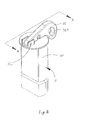
- FIG. 4 is a perspective view of a second reversion assembly of the safety belt unlocking mechanism in accordance with an illustrated embodiment of the present invention
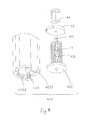
- FIG. 5 is an exploded view of the second reversion assembly shown in FIG. 4 ;
- FIG. 6 is a cross-sectional view of the second reversion assembly taken along line A-A of FIG. 4 ;
- FIG. 7 is a perspective view of a first reversion assembly of the safety belt unlocking mechanism in accordance with an illustrated embodiment of the present invention.
- FIG. 8 is an exploded view of the first reversion assembly shown in FIG. 7 ;
- FIG. 9 is another exploded view of the first reversion assembly shown in FIG. 7 ;
- FIG. 10 is a cross-sectional view of the first reversion assembly taken along line B-B of FIG. 7 .
- the present application discloses a five-point safety belt which includes a two-point safety belt 1 and a three-point safety belt 2.
- two points of the three-point safety belt 2 are arranged at a left side of a passenger, wherein one of the two points is substantially located near a left shoulder of the passenger and the other of the two points is substantially located near a left waist of the passenger.
- At least one of the two points is winded in a belt grabber 23 of a motor vehicle.
- a moveable locking member 22 is mounted between the two points. When in use, the safety belt is pulled from the motor vehicle and the locking member 22 is stretched across a front side of the passenger.
- the locking member 22 is fixed to a locking mechanism 21 located near a right waist of the passenger.
- the safety belt provides two fixing points respectively corresponding to the left shoulder and the left waist of the passenger, and a first fixing point corresponding to the right waist of the passenger. It is understandable that the safety belt provides a whole protection from the left shoulder to the right waist, and from the left waist to the right waist.
- the two-point safety belt 1 is located near a right shoulder of the passenger, wherein one end of the two-point safety belt 1 is winded in another belt grabber 23 and the other end of the two-point safety belt 1 can be pulled out to be fixed to a locking mechanism 11 which is located near the left waist of the passenger.
- the five-point safety belt of the present application not only the left and right shoulders but also the left and right waists of the passenger are provided with locking points which are symmetrical with each other from left to right. As a result, the passenger receives symmetrical forces so as to be more comfortable.
- the safety belt forms a X-shaped cross at a front of the passenger and a horizontal bound of the waist. It is provided with more safety of the passenger because of multiple bounds.
- positions of the three-point safety belt 2 and the two-point safety belt 1 can be exchanged.
- the windable end of the safety belt can also be set near the waist.
- the safety belts 1, 2 are provided with the locking members 12, 22 for locking with the locking mechanisms 11, 21 as so to realize passenger fixation.
- the locking members 12, 22 are ordinarily sheetmetals and include slots 121, 221 through which the safety belts extend. When the locking members 12, 22 are pulled, the safety belts can be extracted accordingly.
- the locking members 12, 22 further include locking holes 122, 222 for mating with the locking mechanisms 11, 21.
- the locking mechanisms 11, 21 include insertion slits 110, 210 into which the locking members 12, 22 are inserted.
- the locking mechanisms 11, 21 are lockable with the locking holes 122, 222 of the locking members 12, 22 so as to realize fixation therebetween.
- the locking mechanisms 11, 21 further include unlocking mechanisms integrally formed therewith. Since the locking mechanisms 11, 21 are usually arranged at waist positions of the passenger, the unlocking mechanisms are usually buttons 111, 211 which are easy for the passenger to apply force thereon. In a specified embodiment, the buttons 111, 211 are usually arranged beside the insertion slits 110, 210 of the locking members 12, 22. When unlocking the locking mechanisms 11, 21 and the locking members 12, 22 are needed, the buttons 111, 211 are downwardly pressed. According to the illustrated embodiment of the present application, a handle 31 is connected below the buttons 111, 211 under condition that when the handle 31 is pulled, the buttons 111, 211 will be driven to slide downwardly and then the locking members 12, 22 are unlocked.
- the handle 31 is connected to each end of the buttons 111, 211 via a cable 41 for pulling the buttons 111, 211.
- the cable 41 is associated with a first reversion assembly 4 which pulls the handle 31 moving towards positions where the buttons 111, 211 return back and helps the handle 31 back to its original position, when the handle 31 is pulled.
- the first reversion assembly 4 includes a first sleeve 42 provided with an upper restricting portion 421 and a lower restricting portion 422, a first sliding member 43 slideable between the upper restricting portion 421 and the lower restricting portion 422, and a first supporting spring 431 mounted between the first sliding member 43 and the lower restricting portion 422.
- the first supporting spring 431 is a coiled spring which is compressed between the first sliding member 43 and the lower restricting portion 422.
- One end of the cable 41 extends through the first sliding member 43 and is provided with an engaging portion 411 fixed on top of the first sliding member 43.
- the first reversion assembly 4 further includes an engaging member 44 on top of the first sliding member 43 for locking the buttons 111, 211.
- the engaging member 44 and the first sliding member 43 are alternatively integral or twopiece.
- the engaging portion 411 of the cable 41 may also extend through the engaging member 44.
- the first sliding member 43 and the engaging member 44 are both driven to slide downwardly under the action of the engaging portion 411 of the cable 41, and then the buttons 111, 211 of the unlocking mechanisms are driven to slide downwardly so as to realize unlocking.
- the first supporting spring 431 restores and drives the first sliding member 43 to move upwardly so as to reset the buttons 111, 211.
- the upper restricting portion 421 includes a protrusion formed on an inner side of the first sleeve 42.
- the inner side of the first sleeve 42 and the first sliding member 43 include a mateable protrusion and a recess along a sliding direction of the first sliding member 43.
- the protrusion of the upper restricting portion 421 can be used to resist against the first sliding member 43 so as to prevent the first sliding member 43 from continuing sliding upwardly.
- the lower restricting portion 422 of the first sleeve 42 includes an opening 423 for loading the first sliding member 43 and the first supporting spring 431 therein.
- the lower restricting portion 422 further includes a slit 4223 corresponding to a bottom side of the opening 423, a first baffle 4221 at bottom of the opening 423 and at least one hook 4222.
- One side of the first baffle 4221 is inserted into the slit 4223 and the other side of the first baffle 4221 is pressed in and locked by the hook 4222.
- the first baffle 4221 is jointly connected to the first sleeve 42 with the hook 4222 fastening the first baffle 4221.
- the above embodiment can be applied to a single two-point safety belt 1, or a single three-point safety belt 2, or any combination thereof.
- buttons 111,211 of the unlocking mechanisms there are two unlocking mechanisms.
- Two cables 41 are provided to be respectively connected to the buttons 111,211 of the unlocking mechanisms. When the buttons 111, 211 are pulled by the cables 41, unlocking the locking members 12, 22 is realized.
- Distal ends of the single cable 41 are respectively connected to two first sliding members 43 of the two first reversion assemblies 4.
- the handle 31 is connected to a middle section of the cable 41 via a second reversion assembly 3.
- the cable 41 When the cable 41 is pulled, it simultaneously drives the two first reversion assemblies 4 and then simultaneously unlocks the two locking mechanisms 11, 21.
- the second reversion assembly 3 includes a second sleeve 32, a second sliding member 33 slideable in the second sleeve 32, and a connecting cable 34 connecting the second sliding member 33 and the handle 31.
- One end of the connecting cable 34 is connected to the second sliding member 33 and the other end of the connecting cable 34 is connected to a middle portion of the handle 31.
- One end of the handle 31 is pivotally mounted to the second sleeve 32 via a spindle 331 and the other end of the handle 31 includes an operation portion for being used by a passenger.
- the one end of the connecting cable 34 includes an engaging portion 341 extending through the second sliding member 33.
- the second reversion assembly 3 further includes a second supporting spring 35 compressed between the second sliding member 33 and one end of the second sleeve 32.
- the second supporting spring 35 is a coiled spring.
- the second supporting spring 35 drives the second sliding member 33 to move along a direction far from the handle 31 so as to reset the handle 31.
- the second sliding member 33 includes a bearing 36 and a pulley 37 mounted to the bearing 36.
- the middle section of the cable 41 two ends of which are connected to the locking mechanisms, spools on the pulley 37.
- the two locking mechanisms 11, 21 may be provided with different distances to the handle 31.
- the above embodiment can be applied to two two-point safety belts 1, or two three-point safety belts 2, or any combination of the two-point safety belt 1 and the three-point safety belt 2.
- the above safety belt unlocking mechanism is set at a position corresponding to each single passenger.
- the safety belts can be respectively arranged on two passengers.
- Each safety belt is provided with a locking mechanism and a corresponding unlocking mechanism.
- Two ends of the cable 41 are respectively connected to the buttons of the unlocking mechanisms corresponding to the two passengers. Through pulling the handle, the safety belts of the two passengers can be unlocked simultaneously for reducing the workload of the passengers.
Landscapes
- Engineering & Computer Science (AREA)
- Mechanical Engineering (AREA)
- Emergency Lowering Means (AREA)
- Automotive Seat Belt Assembly (AREA)
Applications Claiming Priority (2)
| Application Number | Priority Date | Filing Date | Title |
|---|---|---|---|
| CN201110083825.0A CN102729947B (zh) | 2011-04-02 | 2011-04-02 | 五点式安全带及安全带解锁机构 |
| PCT/CN2011/001130 WO2012135984A1 (fr) | 2011-04-02 | 2011-07-08 | Ceinture de sécurité à cinq points et mécanisme de déverrouillage de ceinture de sécurité |
Publications (2)
| Publication Number | Publication Date |
|---|---|
| EP2660108A1 true EP2660108A1 (fr) | 2013-11-06 |
| EP2660108A4 EP2660108A4 (fr) | 2014-07-23 |
Family
ID=46968522
Family Applications (1)
| Application Number | Title | Priority Date | Filing Date |
|---|---|---|---|
| EP11863170.4A Withdrawn EP2660108A4 (fr) | 2011-04-02 | 2011-07-08 | Ceinture de sécurité à cinq points et mécanisme de déverrouillage de ceinture de sécurité |
Country Status (7)
| Country | Link |
|---|---|
| US (1) | US8979130B2 (fr) |
| EP (1) | EP2660108A4 (fr) |
| CN (1) | CN102729947B (fr) |
| BR (1) | BR112013022339A2 (fr) |
| CA (1) | CA2824688A1 (fr) |
| TW (1) | TWM438421U (fr) |
| WO (1) | WO2012135984A1 (fr) |
Cited By (1)
| Publication number | Priority date | Publication date | Assignee | Title |
|---|---|---|---|---|
| TWI636906B (zh) * | 2017-08-31 | 2018-10-01 | 王亮雄 | 多點式安全帶裝置 |
Families Citing this family (4)
| Publication number | Priority date | Publication date | Assignee | Title |
|---|---|---|---|---|
| CN102908730B (zh) * | 2012-11-03 | 2014-10-01 | 中山市金马科技娱乐设备有限公司 | 座椅安全带结构 |
| CN110371302B (zh) * | 2019-07-15 | 2021-03-02 | 北京安达维尔航空设备有限公司 | 一种含有一键解锁装置的伞包背带系统 |
| US20230036452A1 (en) * | 2021-07-28 | 2023-02-02 | Safe, Inc. | Dual three-point restraint system |
| CN115489738B (zh) * | 2022-08-15 | 2024-08-09 | 北京安达维尔航空设备有限公司 | 一种联动解锁机构 |
Family Cites Families (25)
| Publication number | Priority date | Publication date | Assignee | Title |
|---|---|---|---|---|
| FR2523452B1 (fr) * | 1982-03-18 | 1985-11-29 | Alkan R & Cie | Dispositif d'accrochage de sangle a encliquetage et ejection automatiques |
| US5123673A (en) * | 1991-02-28 | 1992-06-23 | Hoover Universal, Inc. | Seat belt system for a vehicle seat |
| US5103771A (en) * | 1991-05-06 | 1992-04-14 | Lee Paul F | Quick release animal leash |
| US7640639B2 (en) * | 1996-10-28 | 2010-01-05 | Debien Products, Inc. | Quick connect coupling assembly |
| US5845377A (en) * | 1997-02-18 | 1998-12-08 | Bibeault; Mark L. | Self actuating mechanical joints |
| US20040113412A1 (en) * | 1997-11-11 | 2004-06-17 | Go Giok Djien | Multi-point seat belt |
| DE19758498C2 (de) * | 1997-11-11 | 2001-07-05 | Giok Djien Go | Rückhaltesystem mit Schulter- und/oder Halshalter zur Erhöhung des Insassenschutzes |
| US6474435B1 (en) * | 2000-09-07 | 2002-11-05 | Trw Vehicle Safety Systems Inc. | Means for electrical connection of components in a vehicle occupant protection system |
| SE517378C2 (sv) * | 2000-10-12 | 2002-06-04 | Volvo Car Corp | Säkerhetsbältesförsträckare |
| US20020089163A1 (en) * | 2001-01-05 | 2002-07-11 | Ford Global Technologies, Inc. | Three-point/four-point seat belt with symmettric belt configuration |
| US6487761B2 (en) * | 2001-01-17 | 2002-12-03 | Charles E. Van Tassel | Quick release buckle for divers |
| SE522470C2 (sv) * | 2001-11-15 | 2004-02-10 | Saab Automobile | Låsarrangemang för säkerhetsbälte |
| US7324191B2 (en) * | 2005-04-01 | 2008-01-29 | Delphi Technologies, Inc. | Optical seat belt tension sensor |
| CN2848646Y (zh) * | 2005-10-09 | 2006-12-20 | 张金文 | 少儿座椅安全带 |
| GB0623949D0 (en) * | 2006-11-30 | 2007-01-10 | Qinetiq Ltd | Occupant restraint |
| US20080252058A1 (en) * | 2007-04-13 | 2008-10-16 | Tk Holdings Inc. | Seatbelt system |
| EP2108550B1 (fr) * | 2008-04-07 | 2011-12-21 | Volvo Car Corporation | Système de ceinture de sécurité et véhicule |
| WO2009143464A2 (fr) * | 2008-05-22 | 2009-11-26 | Paul Carter | Libération de port de charge personnelle |
| EP2286173A2 (fr) * | 2008-05-22 | 2011-02-23 | Paul Carter | Système et procédé permettant une libération rapide |
| JP4876109B2 (ja) * | 2008-07-25 | 2012-02-15 | オートリブ ディベロップメント エービー | 車両用のバックル装置 |
| CN201385639Y (zh) * | 2009-03-26 | 2010-01-20 | 张卫 | 安全带应急脱扣器 |
| US20100313392A1 (en) * | 2009-06-11 | 2010-12-16 | Joseph Anscher | Quick release buckle assembly |
| WO2011079203A1 (fr) * | 2009-12-23 | 2011-06-30 | Bae Systems Aerospace & Defense Group Inc. | Boucle à déclenchement rapide avec double libération |
| US8181318B2 (en) * | 2010-09-03 | 2012-05-22 | National Molding Llc | Buckle assembly |
| CN201961275U (zh) * | 2011-04-02 | 2011-09-07 | 苏州益高电动车辆制造有限公司 | 五点式安全带及安全带解锁机构 |
-
2011
- 2011-04-02 CN CN201110083825.0A patent/CN102729947B/zh not_active Expired - Fee Related
- 2011-07-08 CA CA2824688A patent/CA2824688A1/fr not_active Abandoned
- 2011-07-08 EP EP11863170.4A patent/EP2660108A4/fr not_active Withdrawn
- 2011-07-08 TW TW100212516U patent/TWM438421U/zh not_active IP Right Cessation
- 2011-07-08 WO PCT/CN2011/001130 patent/WO2012135984A1/fr not_active Ceased
- 2011-07-08 BR BR112013022339A patent/BR112013022339A2/pt not_active IP Right Cessation
-
2013
- 2013-07-25 US US13/951,225 patent/US8979130B2/en not_active Expired - Fee Related
Non-Patent Citations (2)
| Title |
|---|
| No further relevant documents disclosed * |
| See also references of WO2012135984A1 * |
Cited By (2)
| Publication number | Priority date | Publication date | Assignee | Title |
|---|---|---|---|---|
| TWI636906B (zh) * | 2017-08-31 | 2018-10-01 | 王亮雄 | 多點式安全帶裝置 |
| US10981536B2 (en) | 2017-08-31 | 2021-04-20 | Liang-Hsiung Wang | Multi-point seat belt assembly |
Also Published As
| Publication number | Publication date |
|---|---|
| US8979130B2 (en) | 2015-03-17 |
| TWM438421U (en) | 2012-10-01 |
| WO2012135984A1 (fr) | 2012-10-11 |
| US20130307255A1 (en) | 2013-11-21 |
| EP2660108A4 (fr) | 2014-07-23 |
| BR112013022339A2 (pt) | 2016-12-06 |
| CN102729947B (zh) | 2014-11-26 |
| CN102729947A (zh) | 2012-10-17 |
| CA2824688A1 (fr) | 2012-10-11 |
Similar Documents
| Publication | Publication Date | Title |
|---|---|---|
| US8979130B2 (en) | Five-point safety belt and safety belt unlocking mechanism | |
| DE102012105695B4 (de) | Kindersitz | |
| US9308890B2 (en) | Reversible 3-point to 4-point seat belt system | |
| EP3483001B1 (fr) | Siège enfant avec barre anti-rebond multi-positions | |
| KR101583952B1 (ko) | 슬라이딩 암레스트 콘솔 개폐장치 | |
| US8627554B1 (en) | Buckle assemblies with swivel and dual release features and associated methods of use and manufacture | |
| US9302644B2 (en) | Reversible 3-point to 4-point seat belt system | |
| KR101305812B1 (ko) | 차량용 시트벨트의 웨빙가이드 회전장치 및 그 회전 제어방법 | |
| US20070246982A1 (en) | Child protection system for motor vehicles | |
| EP2708407B1 (fr) | Siège pour enfants, notamment siège de sécurité pour enfant pour véhicule automobile | |
| DE102016101616B4 (de) | Sicherheitssitz | |
| DE102018120869A1 (de) | Kindersicherheitssitz | |
| EP2952396A1 (fr) | Dispositif de ceinture de sécurité pour siège de véhicule | |
| DE10161289A1 (de) | Sicherheitsgurtsystem | |
| DE602005004476T2 (de) | Zungenabdeckung und diese verwendende Sicherheitsvorrichtung | |
| DE112006001260T5 (de) | Verbesserungen in einem oder in Bezug auf einen Fahrzeugsitz | |
| DE212023000211U1 (de) | Kinderrückhaltesystem | |
| JPH0228125Y2 (fr) | ||
| EP2604137A1 (fr) | Boucle de verrouillage de ceinture de sécurité et dispositif de ceinture de sécurité comprenant une boucle de verrouillage de la ceinture de sécurité | |
| WO2015082539A1 (fr) | Siège de véhicule avec dispositif de verrouillage pour dossier intrinsèquement capable de torsion | |
| DE602005005265T2 (de) | Eine Steckzunge mit einem Greifer und Sicherheitsgurt zur Benutzung desselben | |
| EP1606206B1 (fr) | Dispositif de retenue | |
| KR20230142052A (ko) | 자동차용 안전벨트 높이 조절장치 | |
| KR101869041B1 (ko) | 자동 슬라이딩 래치 스트라이커 구조체 | |
| DE10137681B4 (de) | Sicherheitsgurtschloß |
Legal Events
| Date | Code | Title | Description |
|---|---|---|---|
| PUAI | Public reference made under article 153(3) epc to a published international application that has entered the european phase |
Free format text: ORIGINAL CODE: 0009012 |
|
| 17P | Request for examination filed |
Effective date: 20130729 |
|
| AK | Designated contracting states |
Kind code of ref document: A1 Designated state(s): AL AT BE BG CH CY CZ DE DK EE ES FI FR GB GR HR HU IE IS IT LI LT LU LV MC MK MT NL NO PL PT RO RS SE SI SK SM TR |
|
| DAX | Request for extension of the european patent (deleted) | ||
| A4 | Supplementary search report drawn up and despatched |
Effective date: 20140620 |
|
| RIC1 | Information provided on ipc code assigned before grant |
Ipc: B60R 22/02 20060101ALI20140613BHEP Ipc: A44B 11/25 20060101ALI20140613BHEP Ipc: B60R 22/30 20060101ALI20140613BHEP Ipc: B60R 22/32 20060101ALI20140613BHEP Ipc: B60R 22/00 20060101AFI20140613BHEP |
|
| 17Q | First examination report despatched |
Effective date: 20150818 |
|
| STAA | Information on the status of an ep patent application or granted ep patent |
Free format text: STATUS: THE APPLICATION IS DEEMED TO BE WITHDRAWN |
|
| 18D | Application deemed to be withdrawn |
Effective date: 20160105 |