EP2660442A2 - Protection thermique intégrée et réduction de fuites dans un système d'admission d'air supersonique - Google Patents
Protection thermique intégrée et réduction de fuites dans un système d'admission d'air supersonique Download PDFInfo
- Publication number
- EP2660442A2 EP2660442A2 EP20130166256 EP13166256A EP2660442A2 EP 2660442 A2 EP2660442 A2 EP 2660442A2 EP 20130166256 EP20130166256 EP 20130166256 EP 13166256 A EP13166256 A EP 13166256A EP 2660442 A2 EP2660442 A2 EP 2660442A2
- Authority
- EP
- European Patent Office
- Prior art keywords
- air
- plenum
- flow
- coolant
- flowing
- Prior art date
- Legal status (The legal status is an assumption and is not a legal conclusion. Google has not performed a legal analysis and makes no representation as to the accuracy of the status listed.)
- Withdrawn
Links
- 230000009467 reduction Effects 0.000 title description 3
- 239000002826 coolant Substances 0.000 claims abstract description 80
- 238000001816 cooling Methods 0.000 claims abstract description 19
- 230000007704 transition Effects 0.000 claims abstract description 19
- 230000035939 shock Effects 0.000 claims description 24
- 238000000034 method Methods 0.000 claims description 15
- 239000000203 mixture Substances 0.000 claims description 5
- 230000000740 bleeding effect Effects 0.000 claims description 3
- 241000167880 Hirundinidae Species 0.000 claims 1
- 238000011144 upstream manufacturing Methods 0.000 claims 1
- 239000002699 waste material Substances 0.000 abstract description 6
- 239000007788 liquid Substances 0.000 description 9
- 239000007789 gas Substances 0.000 description 8
- 238000010586 diagram Methods 0.000 description 7
- 230000008569 process Effects 0.000 description 5
- XLYOFNOQVPJJNP-UHFFFAOYSA-N water Substances O XLYOFNOQVPJJNP-UHFFFAOYSA-N 0.000 description 4
- LYCAIKOWRPUZTN-UHFFFAOYSA-N Ethylene glycol Chemical compound OCCO LYCAIKOWRPUZTN-UHFFFAOYSA-N 0.000 description 3
- 238000013461 design Methods 0.000 description 3
- 230000009747 swallowing Effects 0.000 description 3
- 238000013459 approach Methods 0.000 description 2
- 239000012530 fluid Substances 0.000 description 2
- 230000000977 initiatory effect Effects 0.000 description 2
- LVGUZGTVOIAKKC-UHFFFAOYSA-N 1,1,1,2-tetrafluoroethane Chemical compound FCC(F)(F)F LVGUZGTVOIAKKC-UHFFFAOYSA-N 0.000 description 1
- 230000008901 benefit Effects 0.000 description 1
- 238000009835 boiling Methods 0.000 description 1
- 239000012809 cooling fluid Substances 0.000 description 1
- 230000000694 effects Effects 0.000 description 1
- CNKHSLKYRMDDNQ-UHFFFAOYSA-N halofenozide Chemical compound C=1C=CC=CC=1C(=O)N(C(C)(C)C)NC(=O)C1=CC=C(Cl)C=C1 CNKHSLKYRMDDNQ-UHFFFAOYSA-N 0.000 description 1
- 238000009434 installation Methods 0.000 description 1
- 239000000463 material Substances 0.000 description 1
- 238000012986 modification Methods 0.000 description 1
- 230000004048 modification Effects 0.000 description 1
- 238000013022 venting Methods 0.000 description 1
- 239000002912 waste gas Substances 0.000 description 1
Images
Classifications
-
- B—PERFORMING OPERATIONS; TRANSPORTING
- B64—AIRCRAFT; AVIATION; COSMONAUTICS
- B64D—EQUIPMENT FOR FITTING IN OR TO AIRCRAFT; FLIGHT SUITS; PARACHUTES; ARRANGEMENT OR MOUNTING OF POWER PLANTS OR PROPULSION TRANSMISSIONS IN AIRCRAFT
- B64D33/00—Arrangement in aircraft of power plant parts or auxiliaries not otherwise provided for
- B64D33/02—Arrangement in aircraft of power plant parts or auxiliaries not otherwise provided for of combustion air intakes
-
- F—MECHANICAL ENGINEERING; LIGHTING; HEATING; WEAPONS; BLASTING
- F02—COMBUSTION ENGINES; HOT-GAS OR COMBUSTION-PRODUCT ENGINE PLANTS
- F02C—GAS-TURBINE PLANTS; AIR INTAKES FOR JET-PROPULSION PLANTS; CONTROLLING FUEL SUPPLY IN AIR-BREATHING JET-PROPULSION PLANTS
- F02C7/00—Features, components parts, details or accessories, not provided for in, or of interest apart form groups F02C1/00 - F02C6/00; Air intakes for jet-propulsion plants
- F02C7/04—Air intakes for gas-turbine plants or jet-propulsion plants
- F02C7/057—Control or regulation
-
- F—MECHANICAL ENGINEERING; LIGHTING; HEATING; WEAPONS; BLASTING
- F02—COMBUSTION ENGINES; HOT-GAS OR COMBUSTION-PRODUCT ENGINE PLANTS
- F02C—GAS-TURBINE PLANTS; AIR INTAKES FOR JET-PROPULSION PLANTS; CONTROLLING FUEL SUPPLY IN AIR-BREATHING JET-PROPULSION PLANTS
- F02C7/00—Features, components parts, details or accessories, not provided for in, or of interest apart form groups F02C1/00 - F02C6/00; Air intakes for jet-propulsion plants
- F02C7/12—Cooling of plants
- F02C7/14—Cooling of plants of fluids in the plant, e.g. lubricant or fuel
- F02C7/141—Cooling of plants of fluids in the plant, e.g. lubricant or fuel of working fluid
-
- F—MECHANICAL ENGINEERING; LIGHTING; HEATING; WEAPONS; BLASTING
- F02—COMBUSTION ENGINES; HOT-GAS OR COMBUSTION-PRODUCT ENGINE PLANTS
- F02C—GAS-TURBINE PLANTS; AIR INTAKES FOR JET-PROPULSION PLANTS; CONTROLLING FUEL SUPPLY IN AIR-BREATHING JET-PROPULSION PLANTS
- F02C9/00—Controlling gas-turbine plants; Controlling fuel supply in air- breathing jet-propulsion plants
- F02C9/16—Control of working fluid flow
- F02C9/18—Control of working fluid flow by bleeding, bypassing or acting on variable working fluid interconnections between turbines or compressors or their stages
-
- F—MECHANICAL ENGINEERING; LIGHTING; HEATING; WEAPONS; BLASTING
- F02—COMBUSTION ENGINES; HOT-GAS OR COMBUSTION-PRODUCT ENGINE PLANTS
- F02K—JET-PROPULSION PLANTS
- F02K1/00—Plants characterised by the form or arrangement of the jet pipe or nozzle; Jet pipes or nozzles peculiar thereto
- F02K1/28—Plants characterised by the form or arrangement of the jet pipe or nozzle; Jet pipes or nozzles peculiar thereto using fluid jets to influence the jet flow
- F02K1/30—Plants characterised by the form or arrangement of the jet pipe or nozzle; Jet pipes or nozzles peculiar thereto using fluid jets to influence the jet flow for varying effective area of jet pipe or nozzle
-
- F—MECHANICAL ENGINEERING; LIGHTING; HEATING; WEAPONS; BLASTING
- F02—COMBUSTION ENGINES; HOT-GAS OR COMBUSTION-PRODUCT ENGINE PLANTS
- F02K—JET-PROPULSION PLANTS
- F02K7/00—Plants in which the working fluid is used in a jet only, i.e. the plants not having a turbine or other engine driving a compressor or a ducted fan; Control thereof
- F02K7/10—Plants in which the working fluid is used in a jet only, i.e. the plants not having a turbine or other engine driving a compressor or a ducted fan; Control thereof characterised by having ram-action compression, i.e. aero-thermo-dynamic-ducts or ram-jet engines
-
- B—PERFORMING OPERATIONS; TRANSPORTING
- B64—AIRCRAFT; AVIATION; COSMONAUTICS
- B64D—EQUIPMENT FOR FITTING IN OR TO AIRCRAFT; FLIGHT SUITS; PARACHUTES; ARRANGEMENT OR MOUNTING OF POWER PLANTS OR PROPULSION TRANSMISSIONS IN AIRCRAFT
- B64D33/00—Arrangement in aircraft of power plant parts or auxiliaries not otherwise provided for
- B64D33/02—Arrangement in aircraft of power plant parts or auxiliaries not otherwise provided for of combustion air intakes
- B64D2033/0253—Arrangement in aircraft of power plant parts or auxiliaries not otherwise provided for of combustion air intakes specially adapted for particular type of aircraft
- B64D2033/026—Arrangement in aircraft of power plant parts or auxiliaries not otherwise provided for of combustion air intakes specially adapted for particular type of aircraft for supersonic or hypersonic aircraft
-
- F—MECHANICAL ENGINEERING; LIGHTING; HEATING; WEAPONS; BLASTING
- F05—INDEXING SCHEMES RELATING TO ENGINES OR PUMPS IN VARIOUS SUBCLASSES OF CLASSES F01-F04
- F05D—INDEXING SCHEME FOR ASPECTS RELATING TO NON-POSITIVE-DISPLACEMENT MACHINES OR ENGINES, GAS-TURBINES OR JET-PROPULSION PLANTS
- F05D2220/00—Application
- F05D2220/80—Application in supersonic vehicles excluding hypersonic vehicles or ram, scram or rocket propulsion
-
- F—MECHANICAL ENGINEERING; LIGHTING; HEATING; WEAPONS; BLASTING
- F05—INDEXING SCHEMES RELATING TO ENGINES OR PUMPS IN VARIOUS SUBCLASSES OF CLASSES F01-F04
- F05D—INDEXING SCHEME FOR ASPECTS RELATING TO NON-POSITIVE-DISPLACEMENT MACHINES OR ENGINES, GAS-TURBINES OR JET-PROPULSION PLANTS
- F05D2270/00—Control
- F05D2270/01—Purpose of the control system
- F05D2270/17—Purpose of the control system to control boundary layer
-
- Y—GENERAL TAGGING OF NEW TECHNOLOGICAL DEVELOPMENTS; GENERAL TAGGING OF CROSS-SECTIONAL TECHNOLOGIES SPANNING OVER SEVERAL SECTIONS OF THE IPC; TECHNICAL SUBJECTS COVERED BY FORMER USPC CROSS-REFERENCE ART COLLECTIONS [XRACs] AND DIGESTS
- Y02—TECHNOLOGIES OR APPLICATIONS FOR MITIGATION OR ADAPTATION AGAINST CLIMATE CHANGE
- Y02T—CLIMATE CHANGE MITIGATION TECHNOLOGIES RELATED TO TRANSPORTATION
- Y02T50/00—Aeronautics or air transport
- Y02T50/60—Efficient propulsion technologies, e.g. for aircraft
-
- Y—GENERAL TAGGING OF NEW TECHNOLOGICAL DEVELOPMENTS; GENERAL TAGGING OF CROSS-SECTIONAL TECHNOLOGIES SPANNING OVER SEVERAL SECTIONS OF THE IPC; TECHNICAL SUBJECTS COVERED BY FORMER USPC CROSS-REFERENCE ART COLLECTIONS [XRACs] AND DIGESTS
- Y10—TECHNICAL SUBJECTS COVERED BY FORMER USPC
- Y10T—TECHNICAL SUBJECTS COVERED BY FORMER US CLASSIFICATION
- Y10T137/00—Fluid handling
- Y10T137/0536—Highspeed fluid intake means [e.g., jet engine intake]
Definitions
- the present disclosure generally relates to air intake ducting of supersonic propulsion systems and, in particular, to cooling of the engine air intakes of hypersonic vehicles.
- the air intakes of high-speed vehicles benefit from removal of the boundary layer in order to achieve higher thrust.
- One conventional approach to boundary layer removal uses an intake "bleed" system in the inlet surface which allows the boundary layer to flow though the surface and be collected into a plenum. This bleed air is then ducted overboard. At very high speeds, the stagnant bleed air in the plenum becomes very hot as the kinetic energy of the high-speed air is converted to heat as the air is slowed within the plenum. At speeds above Mach 4, these temperatures may exceed the temperature limit of most materials. As a result, conventional high-speed intake systems do not include bleed systems.
- Vehicles using air-breathing engines that initially fly at subsonic speeds and then accelerate to supersonic flight speeds must use air intakes that can accept the supersonic shock wave that enters the air intake during the transition from subsonic to supersonic flight. Allowing the shock wave to travel from the inlet aperture to the intake throat is referred to as “swallowing" the supersonic flow and is necessary to "start” supersonic operation. To accomplish the "starting" process requires a relatively large amount of air to be bled off of the air intake during the subsonic flow.
- active bleed control systems As allowing this same amount of air to bleed off during supersonic flow reduces the efficiency of the engine, active bleed control systems, referred to as "educated bleed slots," are used in conventional systems to adjust the amount of air that is bleeding off of the air intake.
- the disadvantage of active bleed control systems is the increased complexity and weight and reduction in reliability that are inherent in adding moving elements and actuators to a system.
- Some missiles such as the Long Range Strike Weapon being developed by Lockheed Martin, may be launched from aircraft flying at subsonic speeds and then accelerate to supersonic or hypersonic flight speeds.
- the weight of an air vehicle and the efficiency of its propulsion system at supersonic speed both affect the range and/or payload capacity. Reliability is also an important aspect of performance and any additional moving components or actuators may decrease the overall reliability of the air vehicle.
- aerodynamic friction heats the skin of the air vehicle to temperatures of as much as 1200 °F while the operational temperature of internal components, such as electronics, may be limited to a lower temperature, such as 200 °F.
- this cooling is provided by a flow of cooling fluid from an on-board source, for example a bottle of compressed gas, that is continuously being expanded, thereby reducing the temperature of the expanded gas.
- the resulting cold gas coolant is directed to the internal component to be cooled and then the warmed waste coolant is ducted overboard.
- a flow of a liquid coolant such as water, is directed to the internal component to be cooled. The liquid vaporizes thus absorbing heat and the resulting waste gas is ducted overboard.
- the need to an improved air intake adapted to make the transition from subsonic to supersonic operation and achieve improved efficiency at supersonic speeds is met by the disclosed embodiments of the disclosed air intake system that includes a plenum positioned adjacent to the air intake with bleed holes from the air intake and an exhaust port on an exterior surface of the vehicle.
- the plenum receives the waste coolant from an on-board cooling system. As the temperature of the waste coolant is lower than the temperature of the bleed air that entered the plenum from the intake, mixing of the waste coolant with the bleed air in the plenum maintains the temperature of the mixture of gases within the plenum below an operating temperature limit.
- an air intake system suitable for a supersonic vehicle includes a channel comprising an inlet and a side wall and a plenum coupled to the side wall.
- the plenum is configured to accept a flow of coolant.
- the system also includes a porous region in the side wall configured to allow a flow of bleed air from the channel through the porous region of the side wall into the plenum.
- an air intake system for an engine of a supersonic vehicle includes a channel comprising an inlet and a side wall.
- the channel is configured to accept a flow of air and direct the flow of air to the engine.
- the system also includes a plenum coupled to the side wall, a porous region in the side wall configured to bleed off a portion of the air flowing through flow channel through the porous region into the plenum, and a selectable flow of coolant into the plenum. Coolant does not flow into the plenum while air is flowing through the channel at a subsonic speed. Coolant does flow into the plenum while air is flowing through the channel at a supersonic speed.
- a vehicle in certain embodiments, includes an air-breathing engine and a channel comprising an inlet and a side wall.
- the channel is configured to accept a flow of air through the inlet and direct the flow of air to the engine.
- the vehicle also includes a plenum coupled to the side wall, a porous region in the side wall configured to bleed off a portion of the air flowing through flow channel through the porous region into the plenum, and a selectable flow of coolant into the plenum. Coolant does not flow into the plenum while air is flowing through the channel at a subsonic speed. Coolant does flow into the plenum while air is flowing through the channel at a supersonic speed.
- a method of protecting an air intake system on a supersonic vehicle includes the steps of accepting a flow of air having a subsonic velocity and directing the flow of air through a channel to an engine, bleeding off a portion of the air flowing through the channel through a porous portion of a side wall of the channel into a plenum. The portion is sufficient to allow the air flowing through the channel to transition from the subsonic velocity to a supersonic velocity.
- the method also includes the steps of initiating by a processor a flow of coolant into the plenum starting after the air flowing through the channel reaches supersonic velocity.
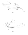
- FIG. 1 depicts an exemplary supersonic vehicle with an air-breathing propulsion system according to certain aspects of the present disclosure.
- FIG. 2 is a schematic diagram of certain components of the vehicle of FIG. 1 according to certain aspects of the present disclosure.
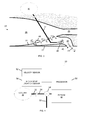
- FIG. 3 is an enlarged view of an exemplary air intake according to certain aspects of the present disclosure.
- FIG. 4 is a block diagram of certain components of the vehicle of FIG. 1 according to certain aspects of the present disclosure.
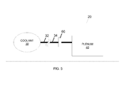
- FIG. 5 is a block diagram of another embodiment of certain components of the vehicle of FIG. 1 according to certain aspects of the present disclosure.
- the term "supersonic” shall be interpreted to indicate a velocity relative to a reference point of greater than the "speed of sound" with respect to reference frame fixed at the reference point.
- a vehicle may be flying through still air at a supersonic velocity relative to that air, while that same air entering an intake channel would have a supersonic velocity relative to the walls of the channel.
- the absolute velocity of sound in air may vary, for example according to the temperature and pressure of the air, and therefore the absolute velocity associated with the "speed of sound” may vary and the determination of whether a velocity is supersonic shall be made relative to the "speed of sound" under the instantaneous conditions at the reference point.
- Machine is sometimes used to state a velocity as a multiple of the "speed of sound.” For example, the phrase “Mach 2" would be approximately twice the "speed of sound.” Within this disclosure, a Mach number is to be interpreted with reference to the "speed of sound” under the instantaneous conditions at the reference point.
- hypersonic is sometimes used to indicate velocities at or above Mach 5.
- supersonic shall be interpreted within this disclosure as inclusive of hypersonic velocities.
- FIG. 1 depicts an exemplary supersonic vehicle 20 with an air-breathing propulsion system 29 (not visible in FIG. 1 ) according to certain aspects of the present disclosure.
- the vehicle 20 has a hull 22 within which is mounted a seeker 28.
- the propulsion system 29 takes in air through inlet 24.
- the details of the air intake system are discussed in greater detail with respect to FIGS. 2 and 3 .
- the vehicle 20 is steered using one or more fins such as the example pair of vertical fins 26A and pair of horizontal fins 26B (the second horizontal fin is not visible in FIG. 1 ).
- the vehicle 20 is launched from an aircraft 2.
- the vehicle 20 is launched from a ship.
- the vehicle 20 is launched from a ground vehicle, such as a truck. In certain embodiments, the vehicle 20 is launched from a mobile or fixed ground-based installation. In certain embodiments, the vehicle 20 takes off from either a ground-based or ship-based runway. In certain embodiments, the vehicle 20 is an unmanned autonomous vehicle. In certain embodiments, the vehicle 20 is teleoperated, i.e. receiving command signals from a remote human operator. In certain embodiments, the vehicle 20 is a manned vehicle.
- the vehicle 20 is launched from the aircraft 2 while the aircraft 2 is flying at a subsonic velocity.
- the propulsion system 29 draws in air at the velocity of the vehicle 20, i.e. air is initially entering the inlet 24 at a subsonic velocity relative to the vehicle 20.
- the velocity of the vehicle 20, and therefore the velocity of the air entering the inlet 24 will reach and then exceed the speed of sound and thereafter the vehicle travels at a supersonic velocity.
- a shock wave forms at the inlet 24.
- the shock wave formed at the inlet 24 must travel through the air intake system to the propulsion system 29, a process referred to as "swallowing" the shock wave. This is discussed in greater detail with respect to FIG. 3 .
- the range and payload capacity of the vehicle 20 depend on the efficiency of the propulsion system 29 while at supersonic speed, since the vehicle 20 may operate primarily at supersonic speeds, it is desirable to reduce the weight of every component and subsystem on the vehicle 20 while increasing the efficiency of the supersonic operation of the propulsion system 29.
- FIG. 2 is a schematic diagram of certain components of the vehicle 20 of FIG. 1 according to certain aspects of the present disclosure.
- the hull 22 is shown as a dash-line outline.
- the propulsion system 29 is located, in this example, at the rear of the vehicle 20.
- the propulsion system 29 is a jet engine.
- the propulsion system 29 is a ramjet engine.
- the propulsion system 29 is a turbine engine.
- the inlet 24 is located on a forward surface of the hull 22 so as to aid in guiding air into the inlet 24.
- the air entering inlet 24 is guided through an air channel 26, also referred to as an air intake, to the propulsion system 29.
- This air channel 26 is not shown to scale or with realistic shape and is presented only schematically as a flow path from the inlet 24 to the propulsion system 29.
- a plenum is located adjacent to a portion of the air channel 26 and shares a side wall with the channel 26. The details of the plenum 40 are discussed in greater detail with respect to FIG. 3 .
- an electronics package 28 is mounted within the hull 22 at a front end of the vehicle 20.
- This electronics package 28 must be maintained within a defined operational temperature range, for example -40 °F to +200 °F. As the hull temperature may reach a temperature, for example 1200 °F, that is in excess of this range, the electronics package 28 must be cooled while the vehicle 20 is flying.
- a tank 30 of coolant is disposed within the hull 22.
- the coolant in the tank 30 is a compressed gas, wherein continuous expansion of a small amount of the compressed gas, which cools the gas, produces a flow of a coolant.
- the coolant in the tank 30 is a pressurized liquid, such as tetrafluoroethane, wherein continuous expansion of a small amount of the pressurized liquid allows the liquid to convert into a cold gas thereby producing a flow of a coolant.
- the coolant in the tank 30 is an unpressurized liquid, such as water or ethylene glycol, and a continuous flow of the liquid from the tank 30 provides the flow of coolant.
- a flow of a liquid coolant is directed from the tank 30 through line 32 to the electronics package 28 and then through line 34 into the plenum 40.
- the vehicle 20 includes a flow valve 56 (not shown) in line 34 that can direct the flow of coolant either into the plenum 40 or through a secondary line 58 (not shown) out through the hull 22.
- the vehicle 20 includes a processor 50 (not shown) coupled to the flow valve 56 so as to configure the valve 56 to direct the coolant to either the plenum 40 or overboard. The valve 56 and processor 50 are discussed in greater detail with respect to FIG. 4 .
- FIG. 3 is an enlarged view of an exemplary air intake 26, or air channel 26, according to certain aspects of the present disclosure.
- the air channel 26 has an inlet 24 at one end and a throat 25 at the other end, wherein air enters the inlet 24 at a velocity close to the velocity of the vehicle 20 relative to the external atmosphere and flows through the air channel 26 to the throat 25.
- the plenum 40 is shown as coupled to a side wall 27 of the air channel 26. In certain embodiments, the plenum 40 wraps around a portion of the air channel 26 such that the plenum 40 is coupled to more than one side wall 27. In certain embodiments, there are a plurality of plenums 40 respectively coupled to one of side walls 27 of the air channel 26.
- a region of the side wall 27 that is coincident with the plenum is porous, i.e. allows air to pass through the side wall 27.
- a plenum is coupled to each sidewall 27 of the air channel 26 so as to remove a boundary layer from the entire perimeter of the air flow through the air channel 26.
- the porous region of side wall 27 comprises a plurality of holes 42 through the side wall 27, wherein the holes 42 are configured to allow an airflow 44 from the air channel 26 through the holes 42 into the plenum 40.
- the plenum 40 comprises an outlet 45 disposed in the hull 22 configured to allow an airflow 46 from the plenum 40 out through the outlet 45 to the external atmosphere.
- the line 34 carrying the warmed coolant from the electronics package 28 terminates in the plenum 40 such that a flow of coolant 36 is provided into the plenum 40.
- the line 34 and the position and configuration of the termination of line 34 are not shown to scale or with realistic shape and are presented only schematically to indicate the introduction of the coolant 36 into the plenum 40.
- the termination of line 34 is positioned proximate to the holes 42 so as to immediately mix the coolant 36 with the airflow 44 entering the plenum through the holes 42.
- the termination of line 34 is a manifold with multiple openings, for example to improve the mixing of the coolant 36 with the airflow 44.
- the coolant 36 is provided from a dedicated source, i.e. a source of coolant used only to cool the plenum 40. This is effective at producing the same effects of cooling the bleed air 44 and increasing the pressure within the plenum 40, at a cost of additional weight and complexity of the overall vehicle 20. This maybe an acceptable tradeoff in certain circumstances and the use of a dedicated source of coolant does not depart from the spirit and scope of the present disclosure.
- a shock wave forms at the inlet 24 as the vehicle 20 accelerates from subsonic to supersonic velocity.
- the shock wave formed at the inlet 24 must travel through the air channel 26 to the throat 25, a process referred to as "swallowing" the shock wave. If the inlet 24 and air channel 26 are sized for supersonic operation, there is too much air flowing through the channel at subsonic speeds to make this transition and the shock wave may not remain within the throat 25, thereby causing instabilities in the air channel 26. Air must be bled off from the air channel 26 to allow the shock wave to pass through the channel 26 and into the throat 25.
- the bleed holes 46 must therefore be sized to enable the air flowing through the air channel 26 to make the transition from subsonic to supersonic velocity to allow the engine of propulsion system 29 to "start" supersonic operation, i.e. for the shock wave to travel through the air channel 26 to the throat 25.
- the air flowing through the channel 26 reaches supersonic velocity, it is still desirable to bleed off the boundary layer of the air flowing through air channel 26.
- the amount of bleed air 44 necessary to remove the boundary layer during supersonic operation is much less than the amount of air that must be bled off during subsonic operation, and therefore the bleed holes 46 that were sized to facilitate the transition from subsonic to supersonic operation are now oversized for efficient operation.
- the supersonic air that passes through the porous region, i.e. the holes 42, into the plenum 40 heats up as the kinetic energy of the supersonic air 44 is converted to thermal energy in the relatively stationary air within the plenum 40.
- the air in the plenum 40 may reach a temperature of 2000 °F in the absence of cooling and exceed the temperature limit, for example 1600 °F, of the air intake system of the vehicle 20, possibly leading to a system failure.
- the coolant 36 coming from the electronics package 28, for example gaseous water produced by boiling of liquid water coolant at the electronics package 28, may be at a temperature of approximately 250° F. While this is warm compared to the maximum operational temperature of the electronics package 28, this is still far cooler than the 2000 °F of the air 44 entering the plenum 40.
- the temperature of the resulting mixture 46 of air and coolant remains at or below a temperature that is less than the temperature limit of the air intake system, thus allowing the bleed air 44, i.e. the boundary layer being removed from the supersonic air flow in the air intake 26, without the cost, space, and weight penalties of a dedicated plenum cooling system.
- the introduction of the coolant 36 also raises the pressure within the plenum 40 compared to the pressure in the plenum 40 when coolant 36 is not being introduced.
- a higher pressure within the plenum 40 reduces the pressure gradient across the holes 42 and, therefore, will reduce the flow rate of the bleed air 44.
- the coolant is, in certain embodiments, selectively introduced into the plenum 40 only after the transition has been made. This reduction in bleed air flow 44 improves the efficiency of supersonic operation of the propulsion system 29.
- FIG. 4 is a block diagram of certain components of the vehicle 20 of FIG. 2 according to certain aspects of the present disclosure.
- the block diagram depicts the valve 56 that can selectively direct the coolant flowing through line 34 to either the plenum 40 or through line 58 to the external atmosphere.
- the valve 56 is controlled by processor 50 which is also coupled, in certain embodiments, to one or more of a velocity sensor 52 and a shock wave location sensor 54.
- the shock wave location sensor 54 is disposed within the air intake system between the inlet 24 and the engine of the propulsion system 29.
- the velocity sensor 52 measures the velocity of the vehicle 20 in the atmosphere.
- the velocity sensor 52 measures the velocity of the air flowing past a point within the channel after the inlet 24.
- the shock wave location sensor 54 is disposed within the air intake system between the inlet 24 and the engine of the propulsion system 29. In certain embodiments, the shock wave location sensor 54 is a shock detector that determines that the shock wave is at the location of the sensor 54. In certain embodiments, the processor 50 is configured to actuate the valve 56 based on one or more of the signals from the velocity sensor 52 and the shock wave location sensor 54 so as to initiate flow of the coolant into the plenum 40.
- FIG. 5 is a block diagram of another embodiment of certain components of the vehicle 20 of FIG. 1 according to certain aspects of the present disclosure. This embodiment is similar to that of FIG. 4 , with the active components of the processor 50, sensors 52, 54, and valve 56 replaced by a mechanical flow controller 60.
- the flow controller 60 is a burst disk, known to those of skill in the art, or similar burstable seal configured to seal the line 34 while the pressure in the line 34 is less than a predetermined burst pressure of the burstable seal and to burst when the pressure in the line 34 exceeds the predetermined pressure and thereafter allow coolant to flow through the flow controller 60 and into the plenum 40.
- the vehicle 20 includes a cooling system, of which the coolant tank 30 is a part, that is configured to absorb heat from the electronics package 28, visible in FIG. 2 , without venting a flow of coolant for a first period of time and then initiating a flow of coolant to the plenum during a second period of time that follows the first period of time.
- the cooling system is configured such that the first period of time exceeds the time that it takes for the vehicle to accelerate to a supersonic velocity and for the air channel to swallow the shock wave.
- the coolant is allowed to flow into the plenum only after the air flowing through the air channel has transitioned to supersonic velocity.
- the concepts disclosed herein provide a system and method for facilitating the transition in operation of an air intake system from subsonic to supersonic operation while also providing improved efficiency of the air intake system at supersonic speeds.
- the amount of bleed air removed from the air intake channel at supersonic speeds is sufficient to remove the boundary layer but reduced from the level of bleed air required to start the supersonic operation of the engine without the need for active systems or actuators.
- the disclosed system reduces the bleed air flow by pressurizing the plenum with coolant from an on-board cooling system.
- the system cools the bleed air using waste coolant from an on-board cooling system already present for cooling components of the vehicle, thereby maintaining the temperature of the mixture of air and coolant below the maximum operating temperature of the air intake system without the cost, space, and weight penalties of a dedicated plenum cooling system.
- the coolant may be any stream of fluid that is at a temperature below that of the bleed air and available for mixing with the bleed air and subsequent discharge to the external atmosphere.
- the coolant may be any source of fluid at a pressure above the pressure produced within the plenum by the bleed air during subsonic operation and available for mixing with the bleed air and subsequent discharge to the external atmosphere.
- top should be understood as referring to an arbitrary frame of reference, rather than to the ordinary gravitational frame of reference.
- a top surface, a bottom surface, a front surface, and a rear surface may extend upwardly, downwardly, diagonally, or horizontally in a gravitational frame of reference.
- a phrase such as an "aspect” does not imply that such aspect is essential to the subject technology or that such aspect applies to all configurations of the subject technology.
- a disclosure relating to an aspect may apply to all configurations, or one or more configurations.
- a phrase such as an aspect may refer to one or more aspects and vice versa.
- a phrase such as an "embodiment” does not imply that such embodiment is essential to the subject technology or that such embodiment applies to all configurations of the subject technology.
- a disclosure relating to an embodiment may apply to all embodiments, or one or more embodiments.
- a phrase such an embodiment may refer to one or more embodiments and vice versa.
Landscapes
- Engineering & Computer Science (AREA)
- Chemical & Material Sciences (AREA)
- Combustion & Propulsion (AREA)
- Mechanical Engineering (AREA)
- General Engineering & Computer Science (AREA)
- Aviation & Aerospace Engineering (AREA)
- Physics & Mathematics (AREA)
- Fluid Mechanics (AREA)
- Structures Of Non-Positive Displacement Pumps (AREA)
- Cooling, Air Intake And Gas Exhaust, And Fuel Tank Arrangements In Propulsion Units (AREA)
Applications Claiming Priority (1)
| Application Number | Priority Date | Filing Date | Title |
|---|---|---|---|
| US13/461,599 US9403600B2 (en) | 2012-05-01 | 2012-05-01 | Integrated thermal protection and leakage reduction in a supersonic air intake system |
Publications (2)
| Publication Number | Publication Date |
|---|---|
| EP2660442A2 true EP2660442A2 (fr) | 2013-11-06 |
| EP2660442A3 EP2660442A3 (fr) | 2014-09-24 |
Family
ID=48325424
Family Applications (1)
| Application Number | Title | Priority Date | Filing Date |
|---|---|---|---|
| EP20130166256 Withdrawn EP2660442A3 (fr) | 2012-05-01 | 2013-05-02 | Protection thermique intégrée et réduction de fuites dans un système d'admission d'air supersonique |
Country Status (2)
| Country | Link |
|---|---|
| US (1) | US9403600B2 (fr) |
| EP (1) | EP2660442A3 (fr) |
Cited By (2)
| Publication number | Priority date | Publication date | Assignee | Title |
|---|---|---|---|---|
| CN104108470A (zh) * | 2014-07-03 | 2014-10-22 | 南京航空航天大学 | 基于埋入式隔道布局的平面埋入式进气道及设计方法 |
| WO2020005387A1 (fr) * | 2018-06-27 | 2020-01-02 | Raytheon Company | Entrée de moteur de véhicule volant comprenant un déflecteur interne et procédé de configuration |
Families Citing this family (8)
| Publication number | Priority date | Publication date | Assignee | Title |
|---|---|---|---|---|
| FR2982588B1 (fr) * | 2011-11-10 | 2013-11-22 | Aircelle Sa | Panneau composite a ecope de prelevement integree |
| US10627199B1 (en) | 2014-10-29 | 2020-04-21 | Moog Inc. | Active cooling system for electronics on a missile |
| US20180208297A1 (en) * | 2017-01-20 | 2018-07-26 | General Electric Company | Nacelle for an aircraft aft fan |
| CN107103117B (zh) * | 2017-03-27 | 2020-09-18 | 北京临近空间飞行器系统工程研究所 | 一种高超声速飞行器控制舵缝隙的热环境设计方法 |
| US10760426B2 (en) | 2017-06-13 | 2020-09-01 | General Electric Company | Turbine engine with variable effective throat |
| RU2663252C1 (ru) * | 2017-08-03 | 2018-08-03 | Открытое акционерное общество "Научно-производственное предприятие "Конверсия" | Система подачи углеводородного топлива для гиперзвукового летательного аппарата и способ подачи топлива в систему |
| CN107967382B (zh) * | 2017-11-20 | 2020-12-18 | 中国运载火箭技术研究院 | 一种吸气式飞行器耦合影响程度评价方法 |
| US11267551B2 (en) * | 2019-11-15 | 2022-03-08 | General Electric Company | System and method for cooling a leading edge of a high speed vehicle |
Citations (2)
| Publication number | Priority date | Publication date | Assignee | Title |
|---|---|---|---|---|
| US3417767A (en) * | 1966-06-13 | 1968-12-24 | North American Rockwell | Self-restarting supersonic inlet |
| US20090072047A1 (en) * | 2005-08-09 | 2009-03-19 | Greene Leonard M | Aircraft defense system and method |
Family Cites Families (28)
| Publication number | Priority date | Publication date | Assignee | Title |
|---|---|---|---|---|
| US2589945A (en) * | 1947-02-28 | 1952-03-18 | Leduc Rene | Athodyd having air permeable converging intake section for boundary layer controls |
| US2811828A (en) * | 1950-12-02 | 1957-11-05 | United Aircraft Corp | Bleed means for confined supersonic flow |
| US3237400A (en) | 1957-04-05 | 1966-03-01 | United Aircraft Corp | Turborocket engine |
| US3733826A (en) | 1964-02-10 | 1973-05-22 | Texaco Experiment Inc | Fuel cooled ram air reaction propulsion engine |
| US3643676A (en) * | 1970-06-15 | 1972-02-22 | Us Federal Aviation Admin | Supersonic air inlet control system |
| US3799475A (en) * | 1971-06-11 | 1974-03-26 | Nasa | Airflow control system for supersonic inlets |
| US3808833A (en) | 1973-04-03 | 1974-05-07 | Us Navy | Compact transpiration cooling system |
| US3911260A (en) * | 1974-05-30 | 1975-10-07 | Nasa | Shock position sensor for supersonic inlets |
| US4275857A (en) * | 1979-11-05 | 1981-06-30 | The United States Of America As Represented By The Secretary Of The Air Force | Cooling system for ramjet engine |
| FR2628790A1 (fr) | 1988-03-16 | 1989-09-22 | Snecma | Propulseur combine turbofusee aerobie |
| DE3909369A1 (de) | 1988-03-31 | 1989-10-26 | Gen Electric | Gasturbinen-spaltsteuerung |
| DE3942022A1 (de) | 1989-12-20 | 1991-06-27 | Mtu Muenchen Gmbh | Verfahren und vorrichtung zur kuehlung eines flugtriebwerkes |
| US5149018A (en) * | 1990-05-17 | 1992-09-22 | The Boeing Company | Cooling system for a hypersonic aircraft |
| US5123242A (en) | 1990-07-30 | 1992-06-23 | General Electric Company | Precooling heat exchange arrangement integral with mounting structure fairing of gas turbine engine |
| DE4131913A1 (de) | 1991-09-25 | 1993-04-08 | Mtu Muenchen Gmbh | Kuehlvorrichtung fuer hyperschall-luftstrahltriebwerke |
| US5236151A (en) | 1991-12-23 | 1993-08-17 | General Electric Company | Thermal barrier structure |
| JPH0914053A (ja) | 1995-06-28 | 1997-01-14 | Ishikawajima Harima Heavy Ind Co Ltd | 超音速機用インテークの抽気装置 |
| GB2345942B (en) | 1998-12-24 | 2002-08-07 | Rolls Royce Plc | Gas turbine engine internal air system |
| US7048229B2 (en) | 2000-09-26 | 2006-05-23 | Techland Research, Inc. | Low sonic boom inlet for supersonic aircraft |
| US7055781B2 (en) | 2003-06-05 | 2006-06-06 | The Boeing Company | Cooled insulation surface temperature control system |
| US7147432B2 (en) | 2003-11-24 | 2006-12-12 | General Electric Company | Turbine shroud asymmetrical cooling elements |
| US8215589B2 (en) * | 2004-01-23 | 2012-07-10 | Janeke Charl E | Reversible space plane |
| JP4457778B2 (ja) * | 2004-06-30 | 2010-04-28 | 株式会社日立製作所 | 高湿分ガスタービン発電プラント |
| FR2883599B1 (fr) | 2005-03-23 | 2010-04-23 | Snecma Moteurs | Dispositif de liaison entre une enceinte de passage d'air de refroidissement et un aubage de distributeur dans une turbomachine |
| US7475545B2 (en) | 2005-04-29 | 2009-01-13 | General Electric Company | Fladed supersonic missile turbojet |
| US8313056B2 (en) * | 2005-07-19 | 2012-11-20 | United Technologies Corporation | Engine heat exchanger with thermoelectric generation |
| US7665310B2 (en) * | 2006-12-27 | 2010-02-23 | General Electric Company | Gas turbine engine having a cooling-air nacelle-cowl duct integral with a nacelle cowl |
| US8720828B2 (en) | 2009-12-03 | 2014-05-13 | The Boeing Company | Extended plug cold plate |
-
2012
- 2012-05-01 US US13/461,599 patent/US9403600B2/en active Active
-
2013
- 2013-05-02 EP EP20130166256 patent/EP2660442A3/fr not_active Withdrawn
Patent Citations (2)
| Publication number | Priority date | Publication date | Assignee | Title |
|---|---|---|---|---|
| US3417767A (en) * | 1966-06-13 | 1968-12-24 | North American Rockwell | Self-restarting supersonic inlet |
| US20090072047A1 (en) * | 2005-08-09 | 2009-03-19 | Greene Leonard M | Aircraft defense system and method |
Cited By (5)
| Publication number | Priority date | Publication date | Assignee | Title |
|---|---|---|---|---|
| CN104108470A (zh) * | 2014-07-03 | 2014-10-22 | 南京航空航天大学 | 基于埋入式隔道布局的平面埋入式进气道及设计方法 |
| CN104108470B (zh) * | 2014-07-03 | 2016-04-13 | 南京航空航天大学 | 基于埋入式隔道布局的平面埋入式进气道及设计方法 |
| WO2020005387A1 (fr) * | 2018-06-27 | 2020-01-02 | Raytheon Company | Entrée de moteur de véhicule volant comprenant un déflecteur interne et procédé de configuration |
| US11053018B2 (en) | 2018-06-27 | 2021-07-06 | Raytheon Company | Flight vehicle engine inlet with internal diverter, and method of configuring |
| AU2019292004B2 (en) * | 2018-06-27 | 2023-07-20 | Raytheon Company | Flight vehicle engine inlet with internal diverter, and method of configuring |
Also Published As
| Publication number | Publication date |
|---|---|
| US9403600B2 (en) | 2016-08-02 |
| EP2660442A3 (fr) | 2014-09-24 |
| US20130291553A1 (en) | 2013-11-07 |
Similar Documents
| Publication | Publication Date | Title |
|---|---|---|
| US9403600B2 (en) | Integrated thermal protection and leakage reduction in a supersonic air intake system | |
| US12252265B2 (en) | Fluidic propulsive system and thrust and lift generator for aerial vehicles | |
| US5149018A (en) | Cooling system for a hypersonic aircraft | |
| CN101168384B (zh) | 高速移动平台的进气口和方法 | |
| US6634595B2 (en) | Method and apparatus for controlling aircraft inlet air flow | |
| US10507930B2 (en) | Airplane with angled-mounted turboprop engine | |
| CA2618661A1 (fr) | Systeme de suppression de la signature infrarouge | |
| US10435135B2 (en) | System, apparatus and methods for hypersonic shockwave muffler | |
| US5490644A (en) | Ducted boundary layer diverter | |
| JP6806474B2 (ja) | 吸気流量制限器 | |
| WO2018000096A1 (fr) | Véhicule aérien à décollage et atterrissage courts | |
| WO2014021742A2 (fr) | Procédé de déplacement de charges dans l'atmosphère de planètes à des vitesses supérieures à la vitesse orbitale et aéronef ultra-hypersonique multimodal à intégration avancée de la cellule pour sa mise en oeuvre | |
| IL261682A (en) | Configuration for vertical takeoff and landing system for aircraft | |
| US9046035B2 (en) | Compression ramp boundary layer removal | |
| EP2691304B1 (fr) | Système de refroidissement aéroporté | |
| SCHMIDT et al. | Dynamics and control of hypersonic vehicles-the integration challenge for the 1990's | |
| Bougas et al. | Propulsion system integration and thrust vectoring aspects for scaled jet UAVs | |
| JP2024178185A (ja) | 圧縮流体エジェクタ及びプロペラ推進システムの組み合わせ | |
| Taguchi et al. | Hypersonic flight experiment plan of pre-cooled turbojet engine | |
| EP2426044A1 (fr) | Écranoplane avec systéme de propulsion hybride | |
| CN101306723A (zh) | 一种改变移动物体与空气的阻力的方法及装置 | |
| Sarnataro | Thermal control of the avionics box for a commercial supersonic aircraft through Reverse Bootstrap cycle | |
| RU2015107953A (ru) | Непадающий самолёт "NS" - Способ и устройство |
Legal Events
| Date | Code | Title | Description |
|---|---|---|---|
| PUAI | Public reference made under article 153(3) epc to a published international application that has entered the european phase |
Free format text: ORIGINAL CODE: 0009012 |
|
| AK | Designated contracting states |
Kind code of ref document: A2 Designated state(s): AL AT BE BG CH CY CZ DE DK EE ES FI FR GB GR HR HU IE IS IT LI LT LU LV MC MK MT NL NO PL PT RO RS SE SI SK SM TR |
|
| AX | Request for extension of the european patent |
Extension state: BA ME |
|
| PUAL | Search report despatched |
Free format text: ORIGINAL CODE: 0009013 |
|
| AK | Designated contracting states |
Kind code of ref document: A3 Designated state(s): AL AT BE BG CH CY CZ DE DK EE ES FI FR GB GR HR HU IE IS IT LI LT LU LV MC MK MT NL NO PL PT RO RS SE SI SK SM TR |
|
| AX | Request for extension of the european patent |
Extension state: BA ME |
|
| RIC1 | Information provided on ipc code assigned before grant |
Ipc: F02K 7/10 20060101ALI20140819BHEP Ipc: F02C 7/057 20060101AFI20140819BHEP Ipc: F02K 1/30 20060101ALI20140819BHEP Ipc: F02C 7/141 20060101ALI20140819BHEP Ipc: B64D 33/02 20060101ALI20140819BHEP Ipc: F02C 9/18 20060101ALI20140819BHEP Ipc: B64C 21/06 20060101ALI20140819BHEP |
|
| 17P | Request for examination filed |
Effective date: 20150324 |
|
| RBV | Designated contracting states (corrected) |
Designated state(s): AL AT BE BG CH CY CZ DE DK EE ES FI FR GB GR HR HU IE IS IT LI LT LU LV MC MK MT NL NO PL PT RO RS SE SI SK SM TR |
|
| 17Q | First examination report despatched |
Effective date: 20171103 |
|
| GRAP | Despatch of communication of intention to grant a patent |
Free format text: ORIGINAL CODE: EPIDOSNIGR1 |
|
| INTG | Intention to grant announced |
Effective date: 20190205 |
|
| STAA | Information on the status of an ep patent application or granted ep patent |
Free format text: STATUS: THE APPLICATION IS DEEMED TO BE WITHDRAWN |
|
| 18D | Application deemed to be withdrawn |
Effective date: 20190618 |