EP2660508B1 - Leuchtanordnung für Kraftfahrzeuge - Google Patents
Leuchtanordnung für Kraftfahrzeuge Download PDFInfo
- Publication number
- EP2660508B1 EP2660508B1 EP13166014.4A EP13166014A EP2660508B1 EP 2660508 B1 EP2660508 B1 EP 2660508B1 EP 13166014 A EP13166014 A EP 13166014A EP 2660508 B1 EP2660508 B1 EP 2660508B1
- Authority
- EP
- European Patent Office
- Prior art keywords
- light
- light guide
- arrangement
- impurity
- region
- Prior art date
- Legal status (The legal status is an assumption and is not a legal conclusion. Google has not performed a legal analysis and makes no representation as to the accuracy of the status listed.)
- Active
Links
Images




Classifications
-
- F—MECHANICAL ENGINEERING; LIGHTING; HEATING; WEAPONS; BLASTING
- F21—LIGHTING
- F21S—NON-PORTABLE LIGHTING DEVICES; SYSTEMS THEREOF; VEHICLE LIGHTING DEVICES SPECIALLY ADAPTED FOR VEHICLE EXTERIORS
- F21S43/00—Signalling devices specially adapted for vehicle exteriors, e.g. brake lamps, direction indicator lights or reversing lights
- F21S43/20—Signalling devices specially adapted for vehicle exteriors, e.g. brake lamps, direction indicator lights or reversing lights characterised by refractors, transparent cover plates, light guides or filters
- F21S43/235—Light guides
- F21S43/249—Light guides with two or more light sources being coupled into the light guide
-
- F—MECHANICAL ENGINEERING; LIGHTING; HEATING; WEAPONS; BLASTING
- F21—LIGHTING
- F21S—NON-PORTABLE LIGHTING DEVICES; SYSTEMS THEREOF; VEHICLE LIGHTING DEVICES SPECIALLY ADAPTED FOR VEHICLE EXTERIORS
- F21S43/00—Signalling devices specially adapted for vehicle exteriors, e.g. brake lamps, direction indicator lights or reversing lights
- F21S43/20—Signalling devices specially adapted for vehicle exteriors, e.g. brake lamps, direction indicator lights or reversing lights characterised by refractors, transparent cover plates, light guides or filters
- F21S43/235—Light guides
- F21S43/236—Light guides characterised by the shape of the light guide
- F21S43/237—Light guides characterised by the shape of the light guide rod-shaped
-
- F—MECHANICAL ENGINEERING; LIGHTING; HEATING; WEAPONS; BLASTING
- F21—LIGHTING
- F21S—NON-PORTABLE LIGHTING DEVICES; SYSTEMS THEREOF; VEHICLE LIGHTING DEVICES SPECIALLY ADAPTED FOR VEHICLE EXTERIORS
- F21S43/00—Signalling devices specially adapted for vehicle exteriors, e.g. brake lamps, direction indicator lights or reversing lights
- F21S43/20—Signalling devices specially adapted for vehicle exteriors, e.g. brake lamps, direction indicator lights or reversing lights characterised by refractors, transparent cover plates, light guides or filters
- F21S43/235—Light guides
- F21S43/236—Light guides characterised by the shape of the light guide
- F21S43/241—Light guides characterised by the shape of the light guide of complex shape
-
- F—MECHANICAL ENGINEERING; LIGHTING; HEATING; WEAPONS; BLASTING
- F21—LIGHTING
- F21S—NON-PORTABLE LIGHTING DEVICES; SYSTEMS THEREOF; VEHICLE LIGHTING DEVICES SPECIALLY ADAPTED FOR VEHICLE EXTERIORS
- F21S43/00—Signalling devices specially adapted for vehicle exteriors, e.g. brake lamps, direction indicator lights or reversing lights
- F21S43/20—Signalling devices specially adapted for vehicle exteriors, e.g. brake lamps, direction indicator lights or reversing lights characterised by refractors, transparent cover plates, light guides or filters
- F21S43/235—Light guides
- F21S43/242—Light guides characterised by the emission area
- F21S43/245—Light guides characterised by the emission area emitting light from one or more of its major surfaces
-
- F—MECHANICAL ENGINEERING; LIGHTING; HEATING; WEAPONS; BLASTING
- F21—LIGHTING
- F21S—NON-PORTABLE LIGHTING DEVICES; SYSTEMS THEREOF; VEHICLE LIGHTING DEVICES SPECIALLY ADAPTED FOR VEHICLE EXTERIORS
- F21S43/00—Signalling devices specially adapted for vehicle exteriors, e.g. brake lamps, direction indicator lights or reversing lights
- F21S43/10—Signalling devices specially adapted for vehicle exteriors, e.g. brake lamps, direction indicator lights or reversing lights characterised by the light source
- F21S43/13—Signalling devices specially adapted for vehicle exteriors, e.g. brake lamps, direction indicator lights or reversing lights characterised by the light source characterised by the type of light source
- F21S43/14—Light emitting diodes [LED]
-
- G—PHYSICS
- G02—OPTICS
- G02B—OPTICAL ELEMENTS, SYSTEMS OR APPARATUS
- G02B6/00—Light guides; Structural details of arrangements comprising light guides and other optical elements, e.g. couplings
- G02B6/0001—Light guides; Structural details of arrangements comprising light guides and other optical elements, e.g. couplings specially adapted for lighting devices or systems
- G02B6/0005—Light guides; Structural details of arrangements comprising light guides and other optical elements, e.g. couplings specially adapted for lighting devices or systems the light guides being of the fibre type
- G02B6/0006—Coupling light into the fibre
-
- G—PHYSICS
- G02—OPTICS
- G02B—OPTICAL ELEMENTS, SYSTEMS OR APPARATUS
- G02B6/00—Light guides; Structural details of arrangements comprising light guides and other optical elements, e.g. couplings
- G02B6/0001—Light guides; Structural details of arrangements comprising light guides and other optical elements, e.g. couplings specially adapted for lighting devices or systems
- G02B6/0005—Light guides; Structural details of arrangements comprising light guides and other optical elements, e.g. couplings specially adapted for lighting devices or systems the light guides being of the fibre type
- G02B6/001—Light guides; Structural details of arrangements comprising light guides and other optical elements, e.g. couplings specially adapted for lighting devices or systems the light guides being of the fibre type the light being emitted along at least a portion of the lateral surface of the fibre
Definitions
- the invention relates to a lighting arrangement for motor vehicles with two light guides which have optical interference point arrangements for light emission, as well as with two light feed pieces, the light entry surfaces of which are assigned to light sources for feeding light into the light guides.
- Such a lighting arrangement is from DE 101 39 578 A1 has become known, namely an interior light for vehicles which has a light guide strand with two light supply branches connected to it.
- the two feed branches with a rectangular cross-section converge, starting from light entry surfaces, and meet a transition area which continuously converts the rectangular cross-section into a circular cross-section in order to then connect to the actual fiber optic strand with an optical imperfection area.
- light-emitting diodes with different spectral distribution eg a white LED and a red LED, are arranged on the light entry surfaces, the light bundles of the two illuminants being divergently coupled into the light guide strand and mixed with one another.
- the DE 10 2005 019 093 A1 shows a multi-section light guide, in which light is radiated into, for example, three legs with different degrees of curvature, which merge in a wedge shape into a common section. Due to the different curvature of the individual legs, the light rays hit the side and decoupling surfaces of the light guide at different angles of incidence, so that light is emitted in a wider solid angle in order to comply with legal regulations, for example. A screen shields unintentional and uncontrolled light escaping in the area of the curved legs.
- the invention is based on the object of creating a lighting arrangement in which light can be coupled in at at least two points, for example in order to be able to generate sufficiently high luminance levels without excessive heating at a light feed point. It has been shown that when using two separate light guides it is difficult to achieve a homogeneous transition of the luminance between such light guides.
- an impurity arrangement is formed on the second light guide, which is shorter than the first light guide, over a portion of its length, the second light guide at a point where it joins the first light guide opens and is arranged in the light emission direction in front of the first light guide, wherein in the light emission direction the impurity arrangement of the second optical waveguide adjoins the impurity arrangement of the first optical waveguide in a transition area, the first and the second optical waveguide being molded in one piece.
- the impurity arrangement of the second light guide adjoins the impurity arrangement of the first light guide in an overlapping manner in the transition region.
- the impurity arrangement of the first light guide extends essentially over its entire length.
- the first light guide lies over the major part of its length in a central region essentially in a plane within which an end region is angled.
- both the first light guide is angled over an area at its feed end and the second light guide is angled over an area at its feed end and the angled areas of both light guides are approximately parallel run towards each other.
- the first and second light guides are injection molded in one piece.
- the lighting arrangement 1 shown in the figures can, for example, frame a headlight of a vehicle over a section of its circumference and serve as a direction indicator or as a daytime running light. In this case, when viewed from the front, the view is in accordance with Fig. 1 , but the lighting arrangement 1 could also be used for other purposes in a vehicle, for example at the rear of a vehicle.
- the lighting arrangement consists of a first light guide 2, which has a light feed piece 3 at its light entry end, the light entry surface 4 of which is associated in a known manner with a first light source 5, for example a light emitting diode, for feeding light into the light guide.
- a first light source 5 for example a light emitting diode
- the light source 5 is seated directly on the light entry surface 4.
- the first light guide 2 lies over most of its length in a central region 2m essentially in a plane within which an end region 2e (in Fig. 2 right) is angled upwards at about 45 ° in this exemplary embodiment.
- the first light guide 2 is angled backwards out of the above-mentioned plane over a region 2a.
- an impurity arrangement 6 which in a known manner, for example, consists of prisms, a roughening or the like. More precisely, the impurity arrangement runs over the angled end region 2e, the essentially straight region 2m and over a slightly curved transition region 2u, which is shown in FIG FIGS. 1 and 2 is delimited by dotted lines, the meaning of which is explained below.
- the lighting arrangement 1 also has a second light guide 7, which also has a light feed piece 8, the light entry surface 9 of which is assigned a second light source 10, which is also located directly on the light entry surface 9 in the case of the second light guide 7.
- the second light guide 7 which in this example is considerably shorter than the first light guide 2, opens at a junction 11 into the first light guide 2, which is located at the light entry end of the central area 2m and at the beginning of the transition area 2u.
- the second light guide 7 is also angled at its feed end 7 over an area 7a, the angled areas 2a and 7a of both light guides 2, 7 running approximately parallel to one another.
- the second light guide 7 As in the case of the first light guide 2, an impurity arrangement 12 is formed on the rear side over a portion of its length.
- the second light guide 7 is spatially so with respect to the first light guide 2 that seen from the front - see Fig. 1 the second light guide 7, at least with that section which is provided with the impurity arrangement 12, lies exactly behind the first light guide 2. In Fig. 1 therefore only the edge of the widened part of the light feed piece 8 can be seen.
- the formation of the lighting arrangement according to the invention leads to the fact that the impurity arrangement 12 of the second light guide 7, viewed from the front, connects to the impurity arrangement 6 of the first light guide 2, or, in other words, that - again viewed from the front - the impurity arrangement 12 of the second optical waveguide 7 ends approximately there , where the impurity arrangement 6 of the first light guide 2 begins.
- the first light guide 2 in the transition region 2u shines forwards through the second light guide 7 and a homogeneous luminous image also results at the transition between the impurity arrangements 6 and 12.
- the impurity arrangements arranged on a rear side of a light guide radiate the light forward in a known manner through the cross section of a light guide.
- the imperfections of the two light guides 2, 7 overlap each other in the transition area, whereby, for example, the density of the imperfections of both light guides decreases in the transition area, and the sum of the luminances of both light guides produces an overall uniform luminous image.
- a third light guide 13 indicated by dashed lines, which is also angled backwards over an area 13a, with a light feed piece 16 has a light entry surface 15 for a third light source 17 and an impurity arrangement 18 and opens into the first light guide 2 at a junction 14.
- the intersection of the light guides must make sense in terms of lighting technology, but the shape also depends on the manufacturing technology used, in particular on the tools used in injection molding processes.
- the tools should be reusable so that they can be separated after casting. However, this creates visible edge lines at the parting lines between the tools.
- the merging area 19 must therefore be subject to a compromise in terms of both lighting technology and manufacturing technology. With an optimization of the light losses and the homogeneity of the light image, the production by injection molding using molding tools and subsequent tool separation should be possible, taking into account demolding devices.
- the shape and shape of this merging area 19 is thus heavily dependent on the respective geometry of the light sticks (position in three-dimensional space, angle and course to one another) and the associated restrictions due to tools and demolding options, which is a feature of the Figures 4 to 9 can be easily recognized by a person skilled in the art.
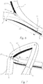
- FIG. 4 Show in the cited figures Fig. 4 an enlarged partial view in a representation similar to FIG Fig. 2 , Fig. 5 an enlarged partial view in a representation similar to FIG Fig. 3 and Fig. 6 a further enlarged partial view similar to FIG Fig. 4 .
- a lighting arrangement according to the invention can be seen the transition area more precisely, wherein Fig. 8 an enlarged area of the Fig. 7 shows and the light guide according to the lines AA and BB of Fig. 7 are cut open.
- the center lines of the light guides 2 and 7 are designated with a and b, through which the said cuts are made.
- Fig. 9 a further perspective partial representation of an entire lighting arrangement according to the invention, the light guides 2, 7 also according to the lines AA and BB of the Fig. 7 cut open and whose center lines are again labeled a and b.
- the light guides have a - mostly preferred - circular cross-section, but the cross-section could, for example, also be elliptical or shaped differently.
- the light guides are usually made of a clear and optically suitable plastic material, it being possible for the first light guide 2 to be formed in one piece with the second light guide 7. Suitable plastics are, to name two examples, polycarbonate or polymethyl methacrylate (acrylic glass).
- front and “rear” as well as “left” and “right” used in connection with the lighting arrangement 1 are not to be understood as restrictive, but rather to mean that an impurity arrangement “rear” is arranged on a light guide, with light pointing towards the "front” is emitted. Only when the lighting arrangement is arranged on the front of a vehicle, for example to frame a headlight, will terms such as “front” and “rear” apply to both the lighting arrangement and the vehicle at least essentially.
Landscapes
- Engineering & Computer Science (AREA)
- General Engineering & Computer Science (AREA)
- Non-Portable Lighting Devices Or Systems Thereof (AREA)
- Planar Illumination Modules (AREA)
- Light Guides In General And Applications Therefor (AREA)
- Lighting Device Outwards From Vehicle And Optical Signal (AREA)
Description
- Die Erfindung bezieht sich auf eine Leuchtanordnung für Kraftfahrzeuge mit zwei Lichtleitern, die optische Störstellenanordnungen zur Lichtabstrahlung aufweisen, sowie mit zwei Lichteinspeisestücken, deren Lichteintrittsflächen Lichtquellen zur Einspeisung von Licht in die Lichtleiter zugeordnet sind.
- Eine solche Leuchtanordnung ist aus der
DE 101 39 578 A1 ist bekannt geworden, nämlich eine Innenleuchte für Fahrzeuge, welche einen Lichtleiterstrang mit zwei an diesen anschließenden Licht-Zuführzweigen aufweist. Die beiden Zuführzweige mit Rechteckquerschnitt konvergieren, ausgehend von Lichteintrittsflächen, und stoßen auf einen Überleitungsbereich, welcher den Rechteckquerschnitt kontinuierlich in einen Kreisquerschnitt überführt, um sodann in den eigentlichen Lichtleiterstrang mit einem optischen Störstellenbereich anzuschließen. Um eine gewünschte Leuchtfarbe zu erreichen, sind an den Lichteintrittsflächen Leuchtdioden mit unterschiedlicher Spektralverteilung, z.B. eine weiße LED und eine rote LED angeordnet, wobei die Lichtbündel der beiden Leuchtmittel divergent in den Lichtleiterstrang eingekoppelt und miteinander vermischt werden. - Die
DE 10 2005 019 093 A1 zeigt einen mehrgliedrigen Lichtleiter, bei welchem Licht in z.B. drei unterschiedlich stark gekrümmte Schenkel, die keilförmig in einen gemeinsamen Abschnitt übergehen, eingestrahlt wird. Durch die unterschiedliche Krümmung der einzelnen Schenkel treffen die Lichtstrahlen mit unterschiedlichen Einfallswinkeln auf die Seiten- und Auskoppelfläche des Lichtleiters, sodass Licht in einen breiteren Raumwinkel abgestrahlt wir, um beispielsweise gesetzlichen Vorschriften zu entsprechen. Eine Blende schirmt im Bereich der gekrümmten Schenkel unbeabsichtigt und ungesteuert austretendes Licht ab. - Der Erfindung liegt die Aufgabe zugrunde, eine Leuchtanordnung zu schaffen, bei welcher an zumindest zwei Stellen Licht eingekoppelt werden kann, beispielsweise um genügend hohe Leuchtdichten erzeugen zu können, ohne eine übermäßige Erwärmung an einer Lichteinspeisestelle zu erhalten. Es hat sich nämlich gezeigt, dass es bei Verwendung zweier getrennter Lichtleiter schwierig ist, einen homogenen Übergang der Leuchtdichte zwischen solchen Lichtleitern zu erreichen.
- Diese Aufgabe wird, ausgehend von einer Leuchtanordnung der eingangs genannten Art dadurch gelöst, dass erfindungsgemäß an dem zweiten Lichtleiter, der kürzer als der erste Lichtleiter ist, über einen Abschnitt seiner Länge eine Störstellenanordnung ausgebildet ist, der zweite Lichtleiter an einer Einmündungsstelle in den ersten Lichtleiter einmündet und in Lichtabstrahlrichtung vor dem ersten Lichtleiter angeordnet ist, wobei in Lichtabstrahlrichtung die Störstellenanordnung des zweiten Lichtleiters in einem Übergangsbereich an die Störstellenanordnung des ersten Lichtleiters anschliesst, wobei der erste und der zweite Lichtleiter einstückig gespritzt ausgebildet sind.
- Dank der Erfindung erhält man trotz Einspeisung des Lichtes an zwei räumlich getrennten Stellen einen optisch und ästhetisch zufriedenstellenden Übergang zwischen den beiden Lichtleitern.
- Im Sinne eines gleichmäßigen Leuchtbildes kann vorgesehen sein, dass die Störstellenanordnung des zweiten Lichtleiters in dem Übergangsbereich an die Störstellenanordnung des ersten Lichtleiters überlappend anschließt. Besonders vorteilhaft ist es in diesem Fall, wenn in dem Überlappungsbereich die Dichte der Störstellen beider Lichtleiter in dem Übergangsbereich abnimmt.
- Es ist weiters zweckmäßig, wenn sich die Störstellenanordnung des ersten Lichtleiters im Wesentlichen über dessen gesamte Länge erstreckt.
- Besonders bei Verwendung in Zusammenhang mit einem Scheinwerfer ist es auch vorteilhaft, wenn der erste Lichtleiter über den größten Teil seiner Länge in einem Mittelbereich im Wesentlichen in einer Ebene liegt, innerhalb der ein Endbereich abgewinkelt ist.
- In der Praxis und insbesondere bei Verwendung in Zusammenhang mit einem Scheinwerfer kann es empfehlenswert sein, wenn sowohl der erste Lichtleiter an seinem Einspeiseende über einen Bereich als auch der zweiten Lichtleiter ist an seinem Einspeiseende über einen Bereich abgewinkelt ist und die abgewinkelten Bereiche beider Lichtleiter annähernd parallel zueinander verlaufen.
- Um einen guten und stabilen Übergang der leuchtenden Bereiche beider Lichtleiter sicherzustellen, sind der erste und der zweite Lichtleiter einstückig gespritzt ausgebildet.
- Die Erfindung samt weiteren Vorteilen ist im Folgenden an Hand einer beispielsweisen Ausführungsform näher erläutert, die in der Zeichnung veranschaulicht ist. In dieser zeigen
-
Fig. 1 eine Ansicht eine Leuchtanordnung nach der Erfindung mit drei Lichtleitern in einer Ansicht von vorne, -
Fig. 2 eine Leuchtanordnung nach der Erfindung mit drei Lichtleitern in einer Ansicht von hinten, -
Fig. 3 eine Leuchtanordnung nach der Erfindung mit zwei Lichtleitern in einer allgemeinen perspektivischen Ansicht, -
Fig. 4 eine vergrößerte Teilansicht in einer Darstellung ähnlich derFig. 2 , -
Fig. 5 eine vergrößerte Teilansicht in einer Darstellung ähnlich derFig. 3 , -
Fig. 6 eine weiter vergrößerte Teilansicht ähnlich derFig. 4 , -
Fig. 7 eine weitere perspektivische Teildarstellung einer Leuchtanordnung nach der Erfindung, welche den Übergangsbereich genauer zeigt, -
Fig. 8 einen vergrößerten Bereich derFig. 7 , wobei die Lichtleiter nach den Linien A-A und B-B derFig. 7 aufgeschnitten sind, und -
Fig. 9 eine weitere perspektivische Teildarstellung einer gesamten Leuchtanordnung nach der Erfindung, wobei die Lichtleiter gleichfalls nach den Linien A-A und B-B derFig. 7 aufgeschnitten sind. - Die in den Figuren gezeigte Leuchtanordnung 1 kann beispielsweise einen Scheinwerfer eines Fahrzeuges über einen Abschnitt seines Umfanges umrahmen und als Fahrtrichtungsanzeiger oder als Tagfahrlicht dienen. In diesem Fall ergibt sich von vorne gesehen die Ansicht nach
Fig. 1 , doch könnte die Leuchtanordnung 1 auch für andere Zwecke in einem Fahrzeug verwendet werden, etwa an der Hinterseite eines Fahrzeugs. - Die Leuchtanordnung besteht aus einem ersten Lichtleiter 2, der an seinem Lichteintrittsende ein Lichteinspeisestück 3 besitzt, wobei dessen Lichteintrittsfläche 4 in bekannter Weise eine erste Lichtquelle 5, beispielsweise eine Leuchtdiode, zur Einspeisung von Licht in den Lichtleiter zugeordnet ist. Bei dem gezeigten Beispiel sitzt die Lichtquelle 5 unmittelbar an der Lichteintrittsfläche 4. Der erste Lichtleiter 2 liegt über den größten Teil seiner Länge in einem Mittelbereich 2m im Wesentlichen in einer Ebene, innerhalb der ein Endbereich 2e (in
Fig. 2 rechts) bei diesem Ausführungsbeispiel unter etwa 45° nach oben abgewinkelt ist. An seinem Einspeiseende ist bei dieser Ausführung der erste Lichtleiter 2 über einen Bereich 2a aus der genannten Ebene heraus nach hinten abgewinkelt. - Wie am besten aus
Fig. 2 ersichtlich, erstreckt sich über den größten Teil der Länge des ersten Lichtleiters 2 an dessen Hinterseite eine Störstellenanordnung 6, die in bekannter Weise beispielsweise aus Prismen, einer Aufrauung od. dgl. besteht. Genauer gesagt, verläuft die Störstellenanordnung über den abgewinkelten Endbereich 2e, den im Wesentlichen geraden Bereich 2m sowie über einen leicht gekrümmten Übergangsbereich 2u, der inFig. 1 und Fig. 2 von punktierten Linien begrenzt ist, und dessen Bedeutung weiter unten erläutert wird. - Die Leuchtanordnung 1 weist auch einen zweiten Lichtleiter 7 auf, der gleichfalls ein Lichteinspeisestück 8 besitzt, dessen Lichteintrittsfläche 9 eine zweite Lichtquelle 10 zugeordnet ist, die auch bei dem zweiten Lichtleiter 7 unmittelbar an der Lichteintrittsfläche 9 sitzt.
- Der zweite Lichtleiter 7, der bei diesem Beispiel erheblich kürzer als der erste Lichtleiter 2 ist, mündet an einer Einmündungsstelle 11 in den ersten Lichtleiter 2, die sich am lichteintrittsseitigen Ende des Mittelbereiches 2m und am Beginn des Übergangsbereiches 2u befindet. Auch der zweiten Lichtleiter 7 ist an seinem Einspeiseende 7 über einen Bereich 7a abgewinkelt, wobei die abgewinkelten Bereiche 2a und 7a beider Lichtleiter 2,7 annähernd parallel zueinander verlaufen.
- Bei dem zweiten Lichtleiter 7 ist, ebenso wie bei dem ersten Lichtleiter 2, an der Hinterseite über einen Abschnitt seiner Länge eine Störstellenanordnung 12 ausgebildet. Dabei liegt der zweite Lichtleiter 7 räumlich so bezüglich des ersten Lichtleiters 2, dass von vorne gesehen - siehe
Fig. 1 - der zweite Lichtleiter 7 zumindest mit jenem Abschnitt, der mit der Störstellenanordnung 12 versehen ist, genau hinter dem ersten Lichtleiter 2 liegt. InFig. 1 ist daher nur der Rand des verbreiterten Teils des Lichteinspeisestücks 8 zu sehen. - Die Ausbildung der erfindungsgemäßen Leuchtanordnung führt dazu, dass die Störstellenanordnung 12 des zweiten Lichtleiters 7 von vorne gesehen an die Störstellenanordnung 6 des ersten Lichtleiters 2 anschließt, oder anders ausgedrückt, dass - wiederum von vorne gesehen - die Störstellenanordnung 12 des zweiten Lichtleiters 7 etwa dort endet, wo die Störstellenanordnung 6 des ersten Lichtleiters 2 beginnt. Dadurch leuchtet der erste Lichtleiter 2 in dem Übergangsbereich 2u durch den zweiten Lichtleiter 7 hindurch nach vorne und es ergibt sich ein homogenes Leuchtbild auch an dem Übergang der Störstellenanordnungen 6 und 12.
- Um Missverständnisse bezüglich der verwendeten Terminologie zu vermeiden, sei hier angemerkt, dass die an einer Hinterseite eines Lichtleiters angeordneten Störstellenanordnungen in bekannter Weise das Licht durch den Querschnitt eines Lichtleiters hindurch nach vorne abstrahlen.
- Es kann aber auch zweckmäßig sein, wenn die Störstellen der beiden Lichtleiter 2, 7 im Übergangsbereich aneinander überlappend anschließen, wobei z.B. die Dichte der Störstellen beider Lichtleiter in dem Übergangsbereich abnimmt, und die Summe der Leuchtdichten beider Lichtleiter ein insgesamt gleichmäßiges Leuchtbild erzeugt.
- Natürlich schließt die Erfindung nicht aus, dass weitere Lichtleiter in den ersten oder zweiten Lichtleiter münden und Licht einspeisen, wie in den Figuren durch einen strichliert angedeuteten dritten Lichtleiter 13 gezeigt ist, welcher gleichfalls über einen Bereich 13a nach hinten abgewinkelt ist, ein Lichteinspeisestück 16 mit einer Lichteintrittsfläche 15 für eine dritte Lichtquelle 17 sowie eine Störstellenanordnung 18 besitzt und an einer Einmündungsstelle 14 in den ersten Lichtleiter 2 mündet.
- Ein besonderes Augenmerk muss dem Zusammenführbereich der Lichtleiter geschenkt werden, der vor allem in den
Fig. 4 bis 9 für den ersten und den zweiten Lichtleiter 2 und 7 näher dargestellt und mit dem Bezugszeichen 19 bezeichnet ist. Die Überschneidung der Lichtleiter muss lichttechnisch sinnvoll sein, doch hängt die Formgebung auch von der verwendeten Fertigungstechnik, insbesondere von den Werkzeugen bei Spritzgussverfahren ab. Die Werkzeuge sollten nämlich wiederverwendbar sein, sodass sie nach dem Gießen getrennt werde. Dadurch aber entstehen an den Trennfugen der Werkzeuge sichtbare Randlinien. - Der Zusammenführbereich 19 muss demnach sowohl einem lichttechnischen als auch fertigungstechnischen Kompromiss unterliegen. Dabei soll unter einer Optimierung der Lichtverluste und der Homogenität des Lichtbildes die Fertigung im Spritzguss durch Formwerkzeuge und anschließender Werkzeugtrennung unter Berücksichtigung von Entformeinrichtungen möglich sein. Die Form und Gestalt dieses Zusammenführbereiches 19 ist somit stark von der jeweiligen Geometrie der Leuchtstäbe (Lage im dreidimensionalen Raum, Winkel und Verlauf zueinander) und der damit verbundenen Beschränkungen durch Werkzeuge- und Entformungsmöglichkeiten abhängig, was in den
Fig. 4 bis 9 für den Fachmann gut erkennbar ist. - In den genannten Figuren zeigen
Fig. 4 eine vergrößerte Teilansicht in einer Darstellung ähnlich derFig. 2 ,Fig. 5 eine vergrößerte Teilansicht in einer Darstellung ähnlich derFig. 3 undFig. 6 eine weiter vergrößerte Teilansicht ähnlich derFig. 4 . - In einer weiteren perspektivischen Teildarstellung nach
Fig. 7 einer Leuchtanordnung nach der Erfindung erkennt man den Übergangsbereich genauer, wobeiFig. 8 einen vergrößerten Bereich derFig. 7 zeigt und die Lichtleiter nach den Linien A-A und B-B derFig. 7 aufgeschnitten sind. Dabei sind mit a und b die Mittellinien der Lichtleiter 2 und 7 bezeichnet, durch welche die genannten Schnitte geführt sind. -
Fig. 9 eine weitere perspektivische Teildarstellung einer gesamten Leuchtanordnung nach der Erfindung, wobei die Lichtleiter 2, 7 gleichfalls nach den Linien A-A und B-B derFig. 7 aufgeschnitten und deren Mittellinien wieder mit a und b bezeichnet sind. - Die Lichtleiter besitzen einen - meist bevorzugten - kreisförmigen Querschnitt, doch könnte der Querschnitt beispielsweise auch elliptisch oder anders geformt sein. Üblicherweise sind die Lichtleiter aus einem klaren und optisch geeigneten Kunststoffmaterial hergestellt, wobei der erste Lichtleiter 2 mit dem zweiten Lichtleiter 7 einstückig ausgebildet sein kann. Geeignete Kunststoffe sind, um zwei Beispiele zu nennen, Polycarbonat oder Polymethylmethacrylat (Acrylglas).
- Die im Zusammenhang mit der Leuchtanordnung 1 verwendeten Begriffe "vorne" und "hinten" sowie "links" und "rechts" sind nicht einschränkend sondern so zu verstehen, dass eine Störstellenanordnung "hinten" an einem Lichtleiter angeordnet ist, wobei Licht nach "vorne" abgestrahlt wird. Nur bei Anordnung der Leuchtanordnung an der Vorderseite eines Fahrzeuges, beispielsweise zur Umrahmung eines Scheinwerfers, werden Begriffe wie "vorne" und "hinten" sowohl auf die Leuchtanordnung als auch auf das Fahrzeug zumindest im Wesentlichen zutreffen.
Claims (6)
- Leuchtanordnung (1) für Kraftfahrzeuge mit zwei Lichtleitern (2, 7), die optische Störstellenanordnungen (6, 12) zur Lichtabstrahlung aufweisen, sowie mit zwei Lichteinspeisestücken (3, 8), welchen Lichtquellen (5, 10) zur Einspeisung von Licht in die Lichtleiter zugeordnet sind,
dadurch gekennzeichnet, dass
an dem zweiten Lichtleiter (7), der kürzer als der erste Lichtleiter (2) ist, über einen Abschnitt seiner Länge eine Störstellenanordnung (12) ausgebildet ist,
der zweite Lichtleiter (7) an einer Einmündungsstelle (11) in den ersten Lichtleiter (2) einmündet und in Lichtabstrahlrichtung vor dem ersten Lichtleiter angeordnet ist, wobei in Lichtabstrahlrichtung die Störstellenanordnung (12) des zweiten Lichtleiters (7) in einem Übergangsbereich (2u) an die Störstellenanordnung (6) des ersten Lichtleiters (2) anschließt, wobei der erste und der zweite Lichtleiter (2,7) einstückig gespritzt ausgebildet sind. - Leuchtanordnung (1) nach Anspruch 1, dadurch gekennzeichnet, dass die Störstellenanordnung (12) des zweiten Lichtleiters (7) in dem Übergangsbereich (2u) an die Störstellenanordnung (6) des ersten Lichtleiters (2) überlappend anschließt.
- Leuchtanordnung (1) nach Anspruch 2, dadurch gekennzeichnet, dass in dem Überlappungsbereich die Dichte der Störstellen (6, 12) beider Lichtleiter (2, 7) in dem Übergangsbereich abnimmt.
- Leuchtanordnung (1) nach einem der Ansprüche 1 bis 3, dadurch gekennzeichnet, dass sich die Störstellenanordnung (6) des ersten Lichtleiters (2) im Wesentlichen über dessen gesamte Länge erstreckt.
- Leuchtanordnung (1) nach einem der Ansprüche 1 bis 4, dadurch gekennzeichnet, dass der erste Lichtleiter (2) über den größten Teil seiner Länge in einem Mittelbereich (2m) im Wesentlichen in einer Ebene liegt, innerhalb der ein Endbereich (2e) abgewinkelt ist.
- Leuchtanordnung (1) nach einem der Ansprüche 1 bis 5, dadurch gekennzeichnet, dass sowohl der erste Lichtleiter (2) an seinem Einspeiseende über einen Bereich (2a) als auch der zweiten Lichtleiter (7) ist an seinem Einspeiseende über einen Bereich (7a) abgewinkelt ist und die abgewinkelten Bereiche (2a und 7a) beider Lichtleiter (2,7) annähernd parallel zueinander verlaufen.
Applications Claiming Priority (1)
| Application Number | Priority Date | Filing Date | Title |
|---|---|---|---|
| ATA50156/2012A AT512803B1 (de) | 2012-05-04 | 2012-05-04 | Leuchtanordnung für Kraftfahrzeuge |
Publications (3)
| Publication Number | Publication Date |
|---|---|
| EP2660508A2 EP2660508A2 (de) | 2013-11-06 |
| EP2660508A3 EP2660508A3 (de) | 2018-01-24 |
| EP2660508B1 true EP2660508B1 (de) | 2021-10-13 |
Family
ID=48190824
Family Applications (1)
| Application Number | Title | Priority Date | Filing Date |
|---|---|---|---|
| EP13166014.4A Active EP2660508B1 (de) | 2012-05-04 | 2013-04-30 | Leuchtanordnung für Kraftfahrzeuge |
Country Status (3)
| Country | Link |
|---|---|
| EP (1) | EP2660508B1 (de) |
| CN (1) | CN103423683B (de) |
| AT (1) | AT512803B1 (de) |
Families Citing this family (8)
| Publication number | Priority date | Publication date | Assignee | Title |
|---|---|---|---|---|
| JP6326963B2 (ja) * | 2014-05-22 | 2018-05-23 | 市光工業株式会社 | 車両用導光部材、車両用灯具 |
| DE102015007664B4 (de) | 2015-06-16 | 2017-07-20 | Audi Ag | Fahrtrichtungsanzeiger für ein Kraftfahrzeug |
| CN106482056B (zh) * | 2015-09-02 | 2021-06-04 | 雅马哈发动机株式会社 | 骑乘型车辆用的灯光装置以及具备该灯光装置的骑乘型车辆 |
| FR3042846B1 (fr) * | 2015-10-23 | 2017-12-01 | Valeo Vision | Dispositif lumineux a guides optiques |
| AT518163B1 (de) * | 2016-02-17 | 2017-08-15 | Zkw Group Gmbh | Lichtleiter für einen Fahrzeugscheinwerfer |
| CN108644735B (zh) * | 2018-04-25 | 2020-03-20 | 东风汽车有限公司 | 动态信号灯及其控制方法 |
| CN111947106B (zh) * | 2020-08-24 | 2025-09-26 | 马瑞利汽车照明系统(佛山)有限公司 | 一种回型位置灯及其组装方法 |
| DE102023124383B3 (de) | 2023-09-11 | 2024-10-02 | Audi Aktiengesellschaft | Lichtleitereinrichtung |
Family Cites Families (8)
| Publication number | Priority date | Publication date | Assignee | Title |
|---|---|---|---|---|
| DE10139578A1 (de) * | 2001-08-10 | 2003-04-10 | Hella Kg Hueck & Co | Innenleuchte für Fahrzeuge |
| DE102005019093B4 (de) * | 2005-03-29 | 2007-02-08 | Fer Fahrzeugelektrik Gmbh | Fahrzeugleuchte mit einem mehrgliedrig gebildeten Lichtleiter |
| DE102007013082A1 (de) * | 2007-03-14 | 2008-09-18 | Hella Kgaa Hueck & Co. | Signalleuchte |
| DE202007014598U1 (de) * | 2007-10-16 | 2009-02-26 | Witte-Velbert Gmbh & Co. Kg | Kennzeichenbeleuchtung |
| JP2011129250A (ja) * | 2008-03-03 | 2011-06-30 | Fujikura Ltd | 照明装置および光の出射方法 |
| JP5007362B2 (ja) * | 2008-03-03 | 2012-08-22 | 株式会社フジクラ | ドアミラー装置 |
| DE102009058457A1 (de) * | 2009-12-16 | 2011-06-22 | Automotive Lighting Reutlingen GmbH, 72762 | Kraftfahrzeugbeleuchtungseinrichtung mit einem Lichtleiter und verschiedenfarbigen Lichtquellen |
| DE102011009100A1 (de) * | 2011-01-21 | 2012-03-15 | Audi Ag | Kraftfahrzeugbeleuchtungseinrichtung zur Innenraumbeleuchtung oder zur Außenbeleuchtung |
-
2012
- 2012-05-04 AT ATA50156/2012A patent/AT512803B1/de active
-
2013
- 2013-04-30 EP EP13166014.4A patent/EP2660508B1/de active Active
- 2013-05-03 CN CN201310159810.7A patent/CN103423683B/zh active Active
Non-Patent Citations (1)
| Title |
|---|
| None * |
Also Published As
| Publication number | Publication date |
|---|---|
| CN103423683A (zh) | 2013-12-04 |
| AT512803B1 (de) | 2013-12-15 |
| AT512803A1 (de) | 2013-11-15 |
| EP2660508A3 (de) | 2018-01-24 |
| EP2660508A2 (de) | 2013-11-06 |
| CN103423683B (zh) | 2016-08-03 |
Similar Documents
| Publication | Publication Date | Title |
|---|---|---|
| AT512803B1 (de) | Leuchtanordnung für Kraftfahrzeuge | |
| DE102016100207B4 (de) | Signalleuchte | |
| AT512056B1 (de) | Lichtleitelement sowie lichteinheit | |
| EP2620790B1 (de) | Leuchtanordnung für Fahrzeuge | |
| DE102013226181B4 (de) | Optisches Element, sowie Anordnung zur Lichtabgabe | |
| DE112014003091T5 (de) | Fahrzeugleuchte | |
| AT517105B1 (de) | Lichtleiteranordnung zur Erzeugung von zumindest einer Beleuchtungsfunktion und/oder Signalisierungsfunktion eines Kraftfahrzeugscheinwerfers | |
| AT517414A1 (de) | Lichtleiteranordnung zur Erzeugung von zumindest einer Beleuchtungsfunktion und/oder Signalisierungsfunktion eines Kraftfahrzeugscheinwerfers | |
| DE102008008180A1 (de) | Kraftfahrzeugbeleuchtungseinrichtung | |
| AT517413B1 (de) | Lichtleiteranordnung zur Erzeugung von zumindest einer Beleuchtungsfunktion und/oder Signalisierungsfunktion eines Kraftfahrzeugscheinwerfers | |
| DE102008021290A1 (de) | Lichtleiterstruktur für eine Kraftfahrzeugbeleuchtungseinrichtung und Kraftfahrzeugbeleuchtungseinrichtung mit einer solchen Lichtleiterstruktur | |
| EP3210827A1 (de) | Leuchte für kraftfahrzeuge | |
| WO2012126575A1 (de) | Fahrzeugleuchte zur beleuchtung des innenraums des fahrzeugs | |
| AT413751B (de) | Leuchtringanordnung | |
| DE102015204747B4 (de) | Beleuchtungseinrichtung für ein Kraftfahrzeug | |
| AT503926A4 (de) | Beleuchtungsvorrichtung zur erzeugung von zumindest einer lichtfunktion für eine lichteinheit oder einen scheinwerfer eines kraftfahrzeuges | |
| EP3531012A1 (de) | Beleuchtungseinrichtung für kraftfahrzeuge mit einem langgestreckten lichtleiter | |
| EP2269901B1 (de) | Balkenförmige Rückleuchte für ein Zweirad | |
| DE102011088702A1 (de) | Lichtleiterstruktur für eine Kraftfahrzeugbeleuchtungseinrichtung | |
| EP3212997B1 (de) | Optisches element sowie anordnung zur lichtabgabe mit einem optischen element | |
| AT505529B1 (de) | Optikelement zur beleuchtung eines fahrzeugkennzeichens | |
| DE102016008422A1 (de) | Leuchte für ein Kraftfahrzeug | |
| DE102007005932B4 (de) | Fahrzeugscheinwerfer mit Lichtleitelement | |
| DE102022123283B3 (de) | Fahrzeugleuchte | |
| DE102017208589A1 (de) | Lichtleiter und Beleuchtungssystem für ein Fahrzeug |
Legal Events
| Date | Code | Title | Description |
|---|---|---|---|
| PUAI | Public reference made under article 153(3) epc to a published international application that has entered the european phase |
Free format text: ORIGINAL CODE: 0009012 |
|
| AK | Designated contracting states |
Kind code of ref document: A2 Designated state(s): AL AT BE BG CH CY CZ DE DK EE ES FI FR GB GR HR HU IE IS IT LI LT LU LV MC MK MT NL NO PL PT RO RS SE SI SK SM TR |
|
| AX | Request for extension of the european patent |
Extension state: BA ME |
|
| RAP1 | Party data changed (applicant data changed or rights of an application transferred) |
Owner name: ZKW GROUP GMBH |
|
| PUAL | Search report despatched |
Free format text: ORIGINAL CODE: 0009013 |
|
| AK | Designated contracting states |
Kind code of ref document: A3 Designated state(s): AL AT BE BG CH CY CZ DE DK EE ES FI FR GB GR HR HU IE IS IT LI LT LU LV MC MK MT NL NO PL PT RO RS SE SI SK SM TR |
|
| AX | Request for extension of the european patent |
Extension state: BA ME |
|
| RIC1 | Information provided on ipc code assigned before grant |
Ipc: F21S 8/10 00000000ALI20171220BHEP Ipc: F21V 8/00 20060101AFI20171220BHEP |
|
| STAA | Information on the status of an ep patent application or granted ep patent |
Free format text: STATUS: REQUEST FOR EXAMINATION WAS MADE |
|
| 17P | Request for examination filed |
Effective date: 20180717 |
|
| RBV | Designated contracting states (corrected) |
Designated state(s): AL AT BE BG CH CY CZ DE DK EE ES FI FR GB GR HR HU IE IS IT LI LT LU LV MC MK MT NL NO PL PT RO RS SE SI SK SM TR |
|
| RIC1 | Information provided on ipc code assigned before grant |
Ipc: F21S 8/10 20181130ALI20171220BHEP Ipc: F21V 8/00 20060101AFI20171220BHEP |
|
| RIC1 | Information provided on ipc code assigned before grant |
Ipc: F21V 8/00 20060101AFI20171220BHEP Ipc: F21S 8/10 20060101ALI20171220BHEP |
|
| RIN1 | Information on inventor provided before grant (corrected) |
Inventor name: TAUDT, LUKAS |
|
| STAA | Information on the status of an ep patent application or granted ep patent |
Free format text: STATUS: EXAMINATION IS IN PROGRESS |
|
| 17Q | First examination report despatched |
Effective date: 20190522 |
|
| RIC1 | Information provided on ipc code assigned before grant |
Ipc: F21V 8/00 20060101AFI20210326BHEP |
|
| GRAP | Despatch of communication of intention to grant a patent |
Free format text: ORIGINAL CODE: EPIDOSNIGR1 |
|
| STAA | Information on the status of an ep patent application or granted ep patent |
Free format text: STATUS: GRANT OF PATENT IS INTENDED |
|
| INTG | Intention to grant announced |
Effective date: 20210510 |
|
| GRAS | Grant fee paid |
Free format text: ORIGINAL CODE: EPIDOSNIGR3 |
|
| GRAA | (expected) grant |
Free format text: ORIGINAL CODE: 0009210 |
|
| STAA | Information on the status of an ep patent application or granted ep patent |
Free format text: STATUS: THE PATENT HAS BEEN GRANTED |
|
| AK | Designated contracting states |
Kind code of ref document: B1 Designated state(s): AL AT BE BG CH CY CZ DE DK EE ES FI FR GB GR HR HU IE IS IT LI LT LU LV MC MK MT NL NO PL PT RO RS SE SI SK SM TR |
|
| REG | Reference to a national code |
Ref country code: GB Ref legal event code: FG4D Free format text: NOT ENGLISH |
|
| REG | Reference to a national code |
Ref country code: CH Ref legal event code: EP |
|
| REG | Reference to a national code |
Ref country code: DE Ref legal event code: R096 Ref document number: 502013015953 Country of ref document: DE |
|
| REG | Reference to a national code |
Ref country code: IE Ref legal event code: FG4D Free format text: LANGUAGE OF EP DOCUMENT: GERMAN |
|
| REG | Reference to a national code |
Ref country code: AT Ref legal event code: REF Ref document number: 1438442 Country of ref document: AT Kind code of ref document: T Effective date: 20211115 |
|
| REG | Reference to a national code |
Ref country code: LT Ref legal event code: MG9D |
|
| REG | Reference to a national code |
Ref country code: NL Ref legal event code: MP Effective date: 20211013 |
|
| PG25 | Lapsed in a contracting state [announced via postgrant information from national office to epo] |
Ref country code: RS Free format text: LAPSE BECAUSE OF FAILURE TO SUBMIT A TRANSLATION OF THE DESCRIPTION OR TO PAY THE FEE WITHIN THE PRESCRIBED TIME-LIMIT Effective date: 20211013 Ref country code: LT Free format text: LAPSE BECAUSE OF FAILURE TO SUBMIT A TRANSLATION OF THE DESCRIPTION OR TO PAY THE FEE WITHIN THE PRESCRIBED TIME-LIMIT Effective date: 20211013 Ref country code: FI Free format text: LAPSE BECAUSE OF FAILURE TO SUBMIT A TRANSLATION OF THE DESCRIPTION OR TO PAY THE FEE WITHIN THE PRESCRIBED TIME-LIMIT Effective date: 20211013 Ref country code: BG Free format text: LAPSE BECAUSE OF FAILURE TO SUBMIT A TRANSLATION OF THE DESCRIPTION OR TO PAY THE FEE WITHIN THE PRESCRIBED TIME-LIMIT Effective date: 20220113 |
|
| PG25 | Lapsed in a contracting state [announced via postgrant information from national office to epo] |
Ref country code: IS Free format text: LAPSE BECAUSE OF FAILURE TO SUBMIT A TRANSLATION OF THE DESCRIPTION OR TO PAY THE FEE WITHIN THE PRESCRIBED TIME-LIMIT Effective date: 20220213 Ref country code: SE Free format text: LAPSE BECAUSE OF FAILURE TO SUBMIT A TRANSLATION OF THE DESCRIPTION OR TO PAY THE FEE WITHIN THE PRESCRIBED TIME-LIMIT Effective date: 20211013 Ref country code: PT Free format text: LAPSE BECAUSE OF FAILURE TO SUBMIT A TRANSLATION OF THE DESCRIPTION OR TO PAY THE FEE WITHIN THE PRESCRIBED TIME-LIMIT Effective date: 20220214 Ref country code: PL Free format text: LAPSE BECAUSE OF FAILURE TO SUBMIT A TRANSLATION OF THE DESCRIPTION OR TO PAY THE FEE WITHIN THE PRESCRIBED TIME-LIMIT Effective date: 20211013 Ref country code: NO Free format text: LAPSE BECAUSE OF FAILURE TO SUBMIT A TRANSLATION OF THE DESCRIPTION OR TO PAY THE FEE WITHIN THE PRESCRIBED TIME-LIMIT Effective date: 20220113 Ref country code: NL Free format text: LAPSE BECAUSE OF FAILURE TO SUBMIT A TRANSLATION OF THE DESCRIPTION OR TO PAY THE FEE WITHIN THE PRESCRIBED TIME-LIMIT Effective date: 20211013 Ref country code: LV Free format text: LAPSE BECAUSE OF FAILURE TO SUBMIT A TRANSLATION OF THE DESCRIPTION OR TO PAY THE FEE WITHIN THE PRESCRIBED TIME-LIMIT Effective date: 20211013 Ref country code: HR Free format text: LAPSE BECAUSE OF FAILURE TO SUBMIT A TRANSLATION OF THE DESCRIPTION OR TO PAY THE FEE WITHIN THE PRESCRIBED TIME-LIMIT Effective date: 20211013 Ref country code: GR Free format text: LAPSE BECAUSE OF FAILURE TO SUBMIT A TRANSLATION OF THE DESCRIPTION OR TO PAY THE FEE WITHIN THE PRESCRIBED TIME-LIMIT Effective date: 20220114 Ref country code: ES Free format text: LAPSE BECAUSE OF FAILURE TO SUBMIT A TRANSLATION OF THE DESCRIPTION OR TO PAY THE FEE WITHIN THE PRESCRIBED TIME-LIMIT Effective date: 20211013 |
|
| REG | Reference to a national code |
Ref country code: DE Ref legal event code: R097 Ref document number: 502013015953 Country of ref document: DE |
|
| PG25 | Lapsed in a contracting state [announced via postgrant information from national office to epo] |
Ref country code: SM Free format text: LAPSE BECAUSE OF FAILURE TO SUBMIT A TRANSLATION OF THE DESCRIPTION OR TO PAY THE FEE WITHIN THE PRESCRIBED TIME-LIMIT Effective date: 20211013 Ref country code: SK Free format text: LAPSE BECAUSE OF FAILURE TO SUBMIT A TRANSLATION OF THE DESCRIPTION OR TO PAY THE FEE WITHIN THE PRESCRIBED TIME-LIMIT Effective date: 20211013 Ref country code: RO Free format text: LAPSE BECAUSE OF FAILURE TO SUBMIT A TRANSLATION OF THE DESCRIPTION OR TO PAY THE FEE WITHIN THE PRESCRIBED TIME-LIMIT Effective date: 20211013 Ref country code: EE Free format text: LAPSE BECAUSE OF FAILURE TO SUBMIT A TRANSLATION OF THE DESCRIPTION OR TO PAY THE FEE WITHIN THE PRESCRIBED TIME-LIMIT Effective date: 20211013 Ref country code: DK Free format text: LAPSE BECAUSE OF FAILURE TO SUBMIT A TRANSLATION OF THE DESCRIPTION OR TO PAY THE FEE WITHIN THE PRESCRIBED TIME-LIMIT Effective date: 20211013 Ref country code: CZ Free format text: LAPSE BECAUSE OF FAILURE TO SUBMIT A TRANSLATION OF THE DESCRIPTION OR TO PAY THE FEE WITHIN THE PRESCRIBED TIME-LIMIT Effective date: 20211013 |
|
| PLBE | No opposition filed within time limit |
Free format text: ORIGINAL CODE: 0009261 |
|
| STAA | Information on the status of an ep patent application or granted ep patent |
Free format text: STATUS: NO OPPOSITION FILED WITHIN TIME LIMIT |
|
| 26N | No opposition filed |
Effective date: 20220714 |
|
| PG25 | Lapsed in a contracting state [announced via postgrant information from national office to epo] |
Ref country code: AL Free format text: LAPSE BECAUSE OF FAILURE TO SUBMIT A TRANSLATION OF THE DESCRIPTION OR TO PAY THE FEE WITHIN THE PRESCRIBED TIME-LIMIT Effective date: 20211013 |
|
| PG25 | Lapsed in a contracting state [announced via postgrant information from national office to epo] |
Ref country code: SI Free format text: LAPSE BECAUSE OF FAILURE TO SUBMIT A TRANSLATION OF THE DESCRIPTION OR TO PAY THE FEE WITHIN THE PRESCRIBED TIME-LIMIT Effective date: 20211013 |
|
| REG | Reference to a national code |
Ref country code: CH Ref legal event code: PL |
|
| REG | Reference to a national code |
Ref country code: BE Ref legal event code: MM Effective date: 20220430 |
|
| PG25 | Lapsed in a contracting state [announced via postgrant information from national office to epo] |
Ref country code: MC Free format text: LAPSE BECAUSE OF FAILURE TO SUBMIT A TRANSLATION OF THE DESCRIPTION OR TO PAY THE FEE WITHIN THE PRESCRIBED TIME-LIMIT Effective date: 20211013 Ref country code: LU Free format text: LAPSE BECAUSE OF NON-PAYMENT OF DUE FEES Effective date: 20220430 Ref country code: LI Free format text: LAPSE BECAUSE OF NON-PAYMENT OF DUE FEES Effective date: 20220430 Ref country code: CH Free format text: LAPSE BECAUSE OF NON-PAYMENT OF DUE FEES Effective date: 20220430 |
|
| PG25 | Lapsed in a contracting state [announced via postgrant information from national office to epo] |
Ref country code: BE Free format text: LAPSE BECAUSE OF NON-PAYMENT OF DUE FEES Effective date: 20220430 |
|
| PG25 | Lapsed in a contracting state [announced via postgrant information from national office to epo] |
Ref country code: IE Free format text: LAPSE BECAUSE OF NON-PAYMENT OF DUE FEES Effective date: 20220430 |
|
| PG25 | Lapsed in a contracting state [announced via postgrant information from national office to epo] |
Ref country code: IT Free format text: LAPSE BECAUSE OF FAILURE TO SUBMIT A TRANSLATION OF THE DESCRIPTION OR TO PAY THE FEE WITHIN THE PRESCRIBED TIME-LIMIT Effective date: 20211013 |
|
| REG | Reference to a national code |
Ref country code: AT Ref legal event code: MM01 Ref document number: 1438442 Country of ref document: AT Kind code of ref document: T Effective date: 20220430 |
|
| P01 | Opt-out of the competence of the unified patent court (upc) registered |
Effective date: 20230528 |
|
| PG25 | Lapsed in a contracting state [announced via postgrant information from national office to epo] |
Ref country code: AT Free format text: LAPSE BECAUSE OF NON-PAYMENT OF DUE FEES Effective date: 20220430 |
|
| PG25 | Lapsed in a contracting state [announced via postgrant information from national office to epo] |
Ref country code: HU Free format text: LAPSE BECAUSE OF FAILURE TO SUBMIT A TRANSLATION OF THE DESCRIPTION OR TO PAY THE FEE WITHIN THE PRESCRIBED TIME-LIMIT; INVALID AB INITIO Effective date: 20130430 |
|
| PG25 | Lapsed in a contracting state [announced via postgrant information from national office to epo] |
Ref country code: MK Free format text: LAPSE BECAUSE OF FAILURE TO SUBMIT A TRANSLATION OF THE DESCRIPTION OR TO PAY THE FEE WITHIN THE PRESCRIBED TIME-LIMIT Effective date: 20211013 Ref country code: CY Free format text: LAPSE BECAUSE OF FAILURE TO SUBMIT A TRANSLATION OF THE DESCRIPTION OR TO PAY THE FEE WITHIN THE PRESCRIBED TIME-LIMIT Effective date: 20211013 |
|
| PG25 | Lapsed in a contracting state [announced via postgrant information from national office to epo] |
Ref country code: TR Free format text: LAPSE BECAUSE OF FAILURE TO SUBMIT A TRANSLATION OF THE DESCRIPTION OR TO PAY THE FEE WITHIN THE PRESCRIBED TIME-LIMIT Effective date: 20211013 |
|
| PG25 | Lapsed in a contracting state [announced via postgrant information from national office to epo] |
Ref country code: MT Free format text: LAPSE BECAUSE OF FAILURE TO SUBMIT A TRANSLATION OF THE DESCRIPTION OR TO PAY THE FEE WITHIN THE PRESCRIBED TIME-LIMIT Effective date: 20211013 |
|
| PGFP | Annual fee paid to national office [announced via postgrant information from national office to epo] |
Ref country code: DE Payment date: 20250422 Year of fee payment: 13 |
|
| PGFP | Annual fee paid to national office [announced via postgrant information from national office to epo] |
Ref country code: FR Payment date: 20250425 Year of fee payment: 13 |
|
| PGFP | Annual fee paid to national office [announced via postgrant information from national office to epo] |
Ref country code: GB Payment date: 20260324 Year of fee payment: 14 |