EP2660554B1 - Véhicule blindé comportant une cloison pare-feu - Google Patents
Véhicule blindé comportant une cloison pare-feu Download PDFInfo
- Publication number
- EP2660554B1 EP2660554B1 EP13165792.6A EP13165792A EP2660554B1 EP 2660554 B1 EP2660554 B1 EP 2660554B1 EP 13165792 A EP13165792 A EP 13165792A EP 2660554 B1 EP2660554 B1 EP 2660554B1
- Authority
- EP
- European Patent Office
- Prior art keywords
- vehicle according
- wall
- fire wall
- armoured vehicle
- partition
- Prior art date
- Legal status (The legal status is an assumption and is not a legal conclusion. Google has not performed a legal analysis and makes no representation as to the accuracy of the status listed.)
- Active
Links
Images

Classifications
-
- F—MECHANICAL ENGINEERING; LIGHTING; HEATING; WEAPONS; BLASTING
- F41—WEAPONS
- F41H—ARMOUR; ARMOURED TURRETS; ARMOURED OR ARMED VEHICLES; MEANS OF ATTACK OR DEFENCE, e.g. CAMOUFLAGE, IN GENERAL
- F41H7/00—Armoured or armed vehicles
- F41H7/02—Land vehicles with enclosing armour, e.g. tanks
- F41H7/04—Armour construction
- F41H7/044—Hull or cab construction other than floors or base plates for increased land mine protection
Definitions
- the technical field of the invention is that of armored vehicles comprising a box inside which are arranged an engine compartment and a passenger compartment.
- Such vehicles are provided with a firewall that separates the passenger compartment engine.
- This firewall thus extends transversely between two side walls of the vehicle body and it also extends vertically between an upper wall and a floor of the body.
- the firewall is intended to provide a protection of the cabin vis-a-vis the noise of the engine.
- This partition also provides thermal protection and it allows in particular to protect the vehicle crew against potential fire starts may be declared at the powertrain.
- Licences FR2864563 , CH345567 and US 4693320 describe a known firewall.
- the known partitions usually comprise at least one flat sheet separating the engine compartment and the passenger compartment.
- a conventional solution is to enhance the protection of the passenger compartment and reduce the protection of other parts of the vehicle, particularly that of the engine compartment.
- firewall wall fixing welds on the side walls must also be reinforced.
- the invention aims to provide a vehicle in which the protection of the passenger compartment by the firewall is reinforced against the blast mines without imposing an increase in this partition.
- the invention relates to an armored vehicle comprising a box inside which are arranged an engine compartment and a passenger compartment separated from each other by a firewall extending transversely between two side walls of the vehicle body and vertically between an upper wall and a floor of the body, vehicle characterized in that the firewall is fixed and thus resting, directly or indirectly, on the side walls by means of weld seams and has an arched profile whose convexity is oriented towards the engine compartment.
- the firewall has an arched profile that extends from one side wall to the other.
- the firewall comprises a median portion having a vaulted profile and which is extended on either side of the medial portion by planar wings.
- the flat wings may be oriented in the extension of the ends of the arched middle part.
- the flat wings may be formed by separate plates attached to the middle part.
- the partition is connected to each wall via a mechanically welded box integral with one of the side walls.
- the armored vehicle according to the invention may comprise a pivoting turret which is fixed at the level of the upper wall of the body and which carries a turret basket disposed in the passenger compartment, the vehicle is then characterized in that the vaulted profile of the Firewall has a concave face surrounding a portion of the turret basket.
- the partition can be fixed to the upper wall of the box by welded joints.
- the partition can be housed in a groove of the upper wall.
- the partition may be connected to the floor by means of a support base which is fixed to the floor and to which it is connected by a shearable connection, the lower edge of the partition being at a distance from the floor itself.
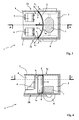
- an armored vehicle 1 comprises a box 2 inside which are arranged an engine compartment 3 and a passenger compartment 4 which are separated from each other by a firewall 5.
- seats 6 are shown which are suspended from an upper wall 2c (or ceiling) of the body 2.
- a power unit 7 which is connected to the means of mobility of the vehicle, here wheels 8.
- the firewall 5 extends transversely between two side walls 2a and 2b of the body 2 of the vehicle ( figure 1 ) and vertically between the upper wall 2c and a floor 2d of the box. It is attached to the various walls by weld beads 9.
- This armored vehicle is a vehicle according to the prior art in which the firewall 5 is formed by a flat plate.
- the Figures 3 and 4 show a vehicle according to a first embodiment of the invention.
- This vehicle differs from the previous one only by the shape of the firewall 5.
- This partition has here an arched profile whose convexity is oriented towards the engine compartment 3 and which extends from a side wall 2a to the other side wall 2b.
- the partition 5 thus has a concave face 5a which is oriented towards the passenger compartment 4 and a convex face 5b which is oriented towards the engine compartment 3.
- Partition 5 is again fixed to the various walls by weld beads 9.
- the arched shape of the partition 5 has the effect of distributing the effort Axial F resulting from the pressure developed inside the engine compartment 3, efforts F 1 and F 2 which are tangent to the profile of the partition 5 at the side edges of this partition (edges in contact with the side walls 2a and 2b).
- the firewall 5 can be made of steel or aluminum in depending on the mechanical constraints it must resist.
- the thickness E of the partition 5 is substantially constant. It is of course possible to make a firewall 5 whose thickness is not constant, for example a partition whose thickness is increasing between its end edges in contact with the walls 2a and 2b and its part median. This solution is however less interesting.
- the arched profile of the partition 5 is here circular in section.
- the partition a profile which is not circular in section, for example a profile with elliptical section, or a vaulted profile at a middle portion and extended by flat wings in support on the side walls.
- a profile which is not circular in section, for example a profile with elliptical section, or a vaulted profile at a middle portion and extended by flat wings in support on the side walls.
- the skilled person will calculate by calculation the shapes and thicknesses of the firewall 5 as a function of the maximum force F to which the partition must resist and maximum forces F 1a and F 2a that can withstand the welds.
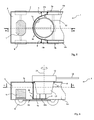
- FIGS. 5 and 6 show a vehicle according to another embodiment of the invention.
- This armored vehicle comprises a pivoting turret 10 which carries a weapon 11.
- the turret 10 is fixed at the level of the upper wall 2c of the body on a circular bearing 12. Only the circular bearing 12 is shown in FIG. figure 5 . With the bearing 12, the turret can rotate relative to the body 2 of the vehicle around a vertical axis 14.
- the turret 10 carries a turret basket 13 which is arranged in the cockpit 4.
- the turret basket 13 is integral in rotation with the turret 10. This basket contains in a conventional manner a gun control station 11 (not shown).
- the firewall 5 comprises a median part having an arched profile and which has a concave face 5a surrounding a portion of the turret basket 13 and a convex face 5b disposed in the engine compartment 3.
- the firewall is connected to each side wall 2a, 2b via a welded box 15a, 15b which is integral with one of the side walls 2a or 2b.
- Each mechanically welded casing 15a, 15b is formed of steel or aluminum plates.
- the structure of each box is defined to be able to withstand the forces F1 and F2 that will be transmitted to it by the partition 5 as a result of the appearance of a pressure in the engine compartment 3.
- the boxes 15a and 15b are also connected to the median part of the partition 5 by weld seams 9. Finally the boxes 15a and 15b are also connected to other caissons 16a and 16b which extend longitudinally along the walls 2a and 2b of the vehicle. The latter boxes are for example the boxes covering the offsets of the wheels 8.
- the sectional profile of the median portion of the firewall 5 is elliptical.
- the partition 5 is supported on the side walls 2a, 2b, indirectly, through the caissons 15a and 15b.
- the support points of the partition 5 on the caissons 15a and 15b are located behind the geometric plane of the major axis of this ellipse.
- the arched shape of the middle portion of the partition 5 will distribute an axial force F, resulting from a pressure developed inside the engine compartment 3, in efforts F 1 and F 2 which are tangent to the profile of the middle part of the partition 5 at its end edges in contact with the caissons 15a and 15b.
- the axial forces (F 1a and F 2a ) to which the welds 9 connecting the caissons 15a, 15b to the body 2 are subjected are reduced.
- the partitioned structure of the caissons 15a, 15b makes it possible to obtain sufficient mechanical strength with sheets of relatively reduced thickness to produce the caissons.
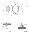
- a wall 5 having a non-constant thickness or a wall associating a concave median portion, circular or elliptical section, extended on each side by flat wings extending the middle portion.
- This partition comprises a median part having an arched profile having a convex face 5b disposed in the engine compartment 3 and a concave face 5a which partially surrounds the circular bearing 12, thus also the turret basket not visible in this figure.
- the median part is extended on both sides by flat wings 5c and 5d which are fixed to the side walls 2a and 2b by weld beads 9.
- planar wings 5c and 5d are formed in one piece with the central arched portion and bear on the side walls 2a and 2b.
- the middle part here has an elliptical section.
- Such a vaulted firewall partition can be easily obtained by folding (rolling or crunching on a press brake) of a sheet steel or aluminum.
- firewall partitions formed of a single vaulted plate (extended or not by flat wings). It is also possible to define a vaulted firewall partition with several walls parallel to each other. Such an arrangement makes it possible to provide different layers of thermal or acoustic insulating materials. Such an arrangement is described in the patent FR2864563 .
- the upper wall 2c may be formed of two parts 2c 1 and 2c 2 which each comprise a half-groove 17.
- a weld bead 9 will provide the connection of the two parts of the ceiling 2c and the partition 5.
- the groove 17 provides the partition 5 a ballistic support.
- the welds 9 are then more resistant to the forces F deployed during the appearance of a breath in the engine compartment 3.
- the partition 5 can be connected to the floor 2d by means of a support base 18 which is itself fixed to the floor by a weld bead 9.
- the partition 5 is connected to the base 18 by a shearable connection ( other weld bead 9 ').
- the lower edge 19 of the partition 5 is also at a distance D from the floor 2d itself.
- the partition slides along the base 18 after shearing of the weld 9 '. Note also that the partition 5 is in ballistic support against the base 18. The forces F which are exerted on the partition 5 as a result of the occurrence of pressure in the engine compartment 3 are taken up by the base 18. This method of connection between a partition and a floor is described in the patent application FR2966231 to which we can refer.
Landscapes
- Engineering & Computer Science (AREA)
- General Engineering & Computer Science (AREA)
- Body Structure For Vehicles (AREA)
Description
- Le domaine technique de l'invention est celui des véhicules blindés comprenant une caisse à l'intérieur de laquelle sont aménagés un compartiment moteur et un habitacle.
- Généralement on prévoit dans de tels véhicules une cloison pare-feu qui permet de séparer l'habitacle du compartiment moteur.
- Cette cloison pare-feu s'étend ainsi transversalement entre deux parois latérales de la caisse du véhicule et elle s'étend aussi verticalement entre une paroi supérieure et un plancher de la caisse.
- La cloison pare-feu a pour but d'assurer une protection de l'habitacle vis à vis du bruit de la motorisation. Cette cloison assure aussi une protection thermique et elle permet notamment de protéger l'équipage du véhicule contre les départs de feu potentiels pouvant se déclarer au niveau du groupe motopropulseur.
-
- Les cloisons connues comportent le plus souvent au moins une tôle plane séparant le compartiment moteur et l'habitacle.
- On cherche aujourd'hui à alléger les véhicules blindés tout en maintenant un bon niveau de protection des équipages contre les mines. Une solution classique consiste à renforcer la protection de l'habitacle et à diminuer la protection des autres parties du véhicule, en particulier celle du compartiment moteur.
- Il se pose alors le problème d'assurer au niveau de la cloison pare-feu une autre fonction qui est la protection de l'habitacle vis à vis du souffle engendré par l'explosion d'une mine sous le compartiment moteur.
- En effet, la protection du compartiment moteur étant réduite, une partie du souffle engendré par la détonation d'une mine va se développer à l'intérieur de ce compartiment et devra être contenue par la cloison pare-feu pour ne pas pénétrer dans l'habitacle.
- Ceci conduit à réaliser une cloison pare-feu à épaisseur renforcée donc à masse augmentée. Par ailleurs les soudures de fixation de la cloison pare-feu sur les parois latérales doivent aussi être renforcées.
- L'invention a pour but de proposer un véhicule dans lequel la protection de l'habitacle par la cloison pare-feu est renforcée vis à vis du souffle des mines sans pour autant imposer un alourdissement de cette cloison.
- Ainsi l'invention a pour objet un véhicule blindé comprenant une caisse à l'intérieur de laquelle sont aménagés un compartiment moteur et un habitacle séparés l'un de l'autre par une cloison pare-feu s'étendant transversalement entre deux parois latérales de la caisse du véhicule et verticalement entre une paroi supérieure et un plancher de la caisse, véhicule caractérisé en ce que la cloison pare-feu est fixée et ainsi en appui, directement ou indirectement, sur les parois latérales par l'intermédiaire de cordons de soudure et présente un profil voûté dont la convexité est orientée vers le compartiment moteur.
- Selon un mode de réalisation, la cloison pare-feu a un profil voûté qui s'étend d'une paroi latérale à l'autre.
- Selon un autre mode de réalisation, la cloison pare-feu comporte une partie médiane ayant un profil voûté et qui est prolongée de part et d'autre de la partie médiane par des ailes planes.
- Les ailes planes pourront être orientées dans le prolongement des extrémités de la partie médiane voûtée.
- Les ailes planes pourront être formées par des plaques distinctes fixées à la partie médiane.
- Selon un autre mode de réalisation, la cloison est raccordée à chaque paroi par l'intermédiaire d'un caisson mécano soudé solidaire d'une des parois latérales.
- Le véhicule blindé selon l'invention peut comporter une tourelle pivotante qui est fixée au niveau de la paroi supérieure de la caisse et qui porte un panier de tourelle disposé dans l'habitacle, le véhicule est alors caractérisé en ce que le profil voûté de la cloison pare-feu a une face concave entourant une partie du panier de tourelle.
- La cloison pourra être fixée à la paroi supérieure de la caisse par des joints soudés.
- La cloison pourra se loger dans une rainure de la paroi supérieure.
- La cloison pourra être liée au plancher par l'intermédiaire d'un socle d'appui qui est fixé au plancher et auquel elle est reliée par une liaison cisaillable, le bord inférieur de la cloison étant à distance du plancher lui-même.
- L'invention sera mieux comprise à la lecture de la description qui va suivre de modes particuliers de réalisation, description faite en référence aux dessins annexés et dans lesquels :
- les
figures 1 et 2 montrent de façon schématique et partielle un véhicule selon l'art antérieur, lafigure 1 le montrant en coupe suivant un plan horizontal dont la trace AA est repérée à lafigure 2 et lafigure 2 une coupe suivant un plan vertical médian dont la trace BB est repérée à lafigure 1 , - les
figures 3 et 4 montrent de façon schématique et partielle un véhicule selon un premier mode de réalisation de l'invention, lafigure 3 le montrant en coupe suivant un plan horizontal dont la trace CC est repérée à lafigure 4 et lafigure 4 une coupe suivant un plan vertical médian dont la trace DD est repérée à lafigure 3 , - les
figures 5 et 6 montrent de façon schématique et partielle un véhicule selon un seconde mode de réalisation de l'invention, lafigure 5 le montrant en coupe suivant un plan horizontal dont la trace GG est repérée à lafigure 6 et lafigure 6 une coupe suivant un plan vertical médian dont la trace HH est repérée à lafigure 5 , - la
figure 7 est une vue de façon schématique et partielle un véhicule selon un troisième mode de réalisation de l'invention, vue en coupe suivant un plan horizontal. - la
figure 8a montre un mode de liaison entre la cloison et la paroi supérieure du véhicule, - la
figure 8b montre un mode de liaison entre la cloison et le plancher du véhicule. - En se reportant aux
figures 1 et 2 , un véhicule blindé 1 comprend une caisse 2 à l'intérieur de laquelle sont aménagés un compartiment moteur 3 et un habitacle 4 qui sont séparés l'un de l'autre par une cloison pare-feu 5. - On a représenté dans l'habitacle 4 des sièges 6 qui sont suspendus à une paroi supérieure 2c (ou plafond) de la caisse 2. On a aussi représenté de façon schématique dans le compartiment moteur 3 un groupe motopropulseur 7 qui est relié aux moyens de mobilité du véhicule, ici des roues 8.
- La cloison pare-feu 5 s'étend transversalement entre deux parois latérales 2a et 2b de la caisse 2 du véhicule (
figure 1 ) et verticalement entre la paroi supérieure 2c et un plancher 2d de la caisse. Elle est fixée aux différentes parois par des cordons de soudure 9. - Ce véhicule blindé est un véhicule selon l'art antérieur dans lequel la cloison pare-feu 5 est formée par une plaque plane.
- Les
figures 3 et 4 montrent un véhicule selon un premier mode de réalisation de l'invention. - Ce véhicule ne diffère du précédent que par la forme de la cloison pare-feu 5.
- Cette cloison présente ici un profil voûté dont la convexité est orientée vers le compartiment moteur 3 et qui s'étend d'une paroi latérale 2a à l'autre paroi latérale 2b.
- La cloison 5 a donc une face concave 5a qui est orientée du côté de l'habitacle 4 et une face convexe 5b qui est orientée vers le compartiment moteur 3.
- Elle s'étend verticalement entre la paroi supérieure 2c et le plancher 2d de la caisse. La cloison 5 est là encore fixée aux différentes parois par des cordons de soudure 9.
- En cas d'apparition d'un souffle à l'intérieur du compartiment moteur 3, souffle dû à l'explosion d'une mine sous le plancher du compartiment moteur, la forme voûtée de la cloison 5 a pour conséquence de répartir l'effort F axial résultant de la pression développée à l'intérieur du compartiment moteur 3, en des efforts F1 et F2 qui sont tangents au profil de la cloison 5 au niveau des bords latéraux de cette cloison (bords en contact avec les parois latérales 2a et 2b).
- La cloison 5 se trouvant en appui directement sur les parois latérales 2a,2b, ces efforts F1 et F2 sont repris en partie par les parois 2a et 2b de la caisse (efforts transversaux F1T et F2T). Les efforts axiaux (F1a et F2a) auxquels sont soumis les soudures 9 sont donc réduits.
- Il est donc possible ainsi de définir une cloison pare-feu 5 dont la résistance mécanique est accrue sans que la masse de ladite cloison ne soit augmentée. Il est également possible de diminuer l'épaisseur du plancher au niveau du compartiment moteur du véhicule, la cloison pare-feu 5 assurant alors la protection de l'habitacle 3. La cloison pare-feu pourra être réalisée en acier ou bien en aluminium en fonction des contraintes mécaniques auxquelles elle doit résister.
- On peut avec un profil de cloison à section circulaire tel que représenté, réduire la masse de la cloison de près de 30% par rapport à une cloison plane comme représentée aux
figures 1 et 2 , tout en ayant une résistance équivalente au souffle d'une mine. - Sur l'exemple représenté, l'épaisseur E de la cloison 5 est sensiblement constante. Il est bien sûr possible de réaliser une cloison pare-feu 5 dont l'épaisseur n'est pas constante, par exemple une cloison dont l'épaisseur est croissante entre ses bords d'extrémité en contact avec les parois 2a et 2b et sa partie médiane. Cette solution est cependant moins intéressante.
- Le profil voûté de la cloison 5 est ici circulaire en section.
- Il est bien entendu possible d'adopter pour la cloison un profil qui n'est pas circulaire en section, par exemple un profil à section elliptique, ou bien un profil voûté au niveau d'une partie médiane et prolongé par des ailes planes en appui sur les parois latérales. Un tel mode de réalisation sera décrit par la suite en référence à la
figure 7 . - Concrètement l'Homme du Métier définira par calcul les formes et épaisseurs de la cloison pare-feu 5 en fonction de l'effort F maximal auquel la cloison doit résister et des efforts maximaux F1a et F2a que peuvent supporter les soudures.
- Les
figures 5 et 6 montrent un véhicule selon un autre mode de réalisation de l'invention. - Ce véhicule blindé comporte une tourelle pivotante 10 qui porte une arme 11. La tourelle 10 est fixée au niveau de la paroi supérieure 2c de la caisse sur un roulement circulaire 12. Seul le roulement circulaire 12 est représenté à la
figure 5 . Grâce au roulement 12, la tourelle peut pivoter par rapport à la caisse 2 du véhicule autour d'un axe vertical 14. - La tourelle 10 porte un panier de tourelle 13 qui est disposé dans l'habitacle 4.
- Le panier de tourelle 13 est solidaire en rotation de la tourelle 10. Ce panier renferme d'une façon classique un poste de commande du tir de l'arme 11 (non représenté).
- Suivant ce mode de réalisation la cloison pare-feu 5 comporte une partie médiane ayant un profil voûté et qui comporte une face concave 5a entourant une partie du panier de tourelle 13 et une face convexe 5b disposée dans le compartiment moteur 3.
- La cloison pare-feu est raccordée à chaque paroi latérale 2a, 2b par l'intermédiaire d'un caisson mécano soudé 15a,15b qui est solidaire d'une des parois latérales 2a ou 2b.
- Chaque caisson mécano soudé 15a,15b est formé de plaques en acier ou en aluminium. La structure de chaque caisson est définie pour pouvoir résister aux efforts F1 et F2 qui lui seront transmis par la cloison 5 comme suite à l'apparition d'une pression dans le compartiment moteur 3.
- Les caissons 15a et 15b sont également liés à la partie médiane de la cloison 5 par des cordons de soudure 9. Enfin les caissons 15a et 15b sont aussi reliés à d'autres caissons 16a et 16b qui s'étendent longitudinalement le long des parois 2a et 2b du véhicule. Ces derniers caissons sont par exemple les caissons coiffant les déports des roues 8.
- Comme on le voit sur la
figure 5 , le profil en section de la partie médiane de la cloison pare-feu 5 est elliptique. La cloison 5 se trouve en appui sur les parois latérales 2a,2b, de façon indirecte, par l'intermédiaire des caissons 15a et 15b. - Les points d'appui de la cloison 5 sur les caissons 15a et 15b se situent en arrière du plan géométrique du grand axe de cette ellipse. Ainsi, comme dans le mode de réalisation précédent, la forme voûtée de la partie médiane de la cloison 5 répartira un effort F axial, résultant d'une pression développée à l'intérieur du compartiment moteur 3, en des efforts F1 et F2 qui sont tangents au profil de la partie médiane de la cloison 5 au niveau de ses bords d'extrémité en contact avec les caissons 15a et 15b.
- Ces efforts F1 et F2 sont repris en partie par les parois 2a et 2b de la caisse via les caissons 15a et 15b.
- Les efforts axiaux (F1a et F2a) auxquels sont soumis les soudures 9 reliant les caissons 15a, 15b à la caisse 2 sont donc réduits. Par ailleurs la structure cloisonnée des caissons 15a, 15b permet d'obtenir une résistance mécanique suffisante avec des tôles d'épaisseur relativement réduite pour réaliser les caissons.
- Là encore on pourra définir une cloison 5 ayant une épaisseur non constante ou bien une cloison associant une partie médiane concave, à section circulaire ou elliptique, prolongée de chaque côté par des ailes planes prolongeant la partie médiane.
- A titre d'exemple on a représenté ainsi sur la
figure 7 une cloison 5 en coupe suivant un plan horizontal. - Cette cloison comporte une partie médiane ayant un profil voûté comportant une face convexe 5b disposée dans le compartiment moteur 3 et une face concave 5a qui entoure partiellement le roulement circulaire 12, donc aussi le panier de tourelle non visible sur cette figure.
- La partie médiane est prolongée de part et d'autre par des ailes planes 5c et 5d qui sont fixées aux parois latérales 2a et 2b par des cordons de soudure 9.
- Dans ce mode de réalisation les ailes planes 5c et 5d sont formées d'une seule pièce avec la partie médiane voûtée et sont en appui sur les parois latérales 2a et 2b.
- La partie médiane a ici une section elliptique.
- Une telle cloison pare-feu voûtée peut être facilement obtenue par pliage (roulage ou bien croquage sur presse plieuse) d'une tôle en acier ou en aluminium.
- D'autres variantes sont possibles sans sortir du cadre de l'invention. On a décrit précédemment des cloisons pare-feu formées d'une seule plaque voûtée (prolongée ou non par des ailes planes). Il est également possible de définir une cloison pare-feu voûtée comportant plusieurs parois parallèles les unes aux autres. Une telle disposition permet de prévoir différentes couches de matériaux isolants thermiques ou acoustiques. Une telle disposition est décrite dans le brevet
FR2864563 - Afin d'améliorer la résistance de la cloison 5 aux effets d'un souffle de mine on pourra, comme le montre la
figure 8a , loger le bord supérieur de la cloison 5 dans une rainure 17 aménagée dans la paroi supérieure 2c. La rainure aura bien sûr une forme courbe adaptée à la courbure de la cloison 5. - La paroi supérieure 2c pourra être formée de deux parties 2c1 et 2c2 qui comportent chacune une demi-rainure 17. Un cordon de soudure 9 assurera la liaison des deux parties du plafond 2c et de la cloison 5.
- La rainure 17 procure à la cloison 5 un appui balistique. Les soudures 9 résistent alors plus facilement aux efforts F déployés lors de l'apparition d'un souffle dans le compartiment moteur 3.
- Selon un mode de réalisation représenté à la
figure 8b , la cloison 5 peut être liée au plancher 2d par l'intermédiaire d'un socle d'appui 18 qui est lui-même fixé au plancher par un cordon de soudure 9. La cloison 5 est liée au socle 18 par une liaison cisaillable (autre cordon de soudure 9'). Le bord inférieur 19 de la cloison 5 est par ailleurs à une distance D du plancher 2d lui-même. Avec une telle structure, une déformation du plancher 2d (comme suite par exemple à la détonation d'une mine sous le plancher) ne vient pas impacter le bord inférieur de la cloison 5. - La cloison glisse le long du socle 18 après cisaillement de la soudure 9'. On note par ailleurs que la cloison 5 se trouve en appui balistique contre le socle 18. Les efforts F qui s'exercent sur la cloison 5 comme suite à l'apparition d'une pression dans le compartiment moteur 3 sont donc repris par le socle 18. Ce mode de liaison entre une cloison et un plancher est décrit dans la demande de brevet
FR2966231
Claims (10)
- Véhicule blindé (1) comprenant une caisse (2) à l'intérieur de laquelle sont aménagés un compartiment moteur (3) et un habitacle (4) séparés l'un de l'autre par une cloison pare-feu (5) s'étendant transversalement entre deux parois latérales (2a,2b) de la caisse du véhicule et verticalement entre une paroi supérieure (2c) et un plancher (2d) de la caisse, véhicule caractérisé en ce que la cloison pare-feu (5) est fixée, et ainsi en appui, directement ou indirectement, sur les parois latérales (2a,2b) par l'intermédiaire de cordons de soudure (9) et présente un profil voûté dont la convexité est orientée vers le compartiment moteur (3).
- Véhicule blindé selon la revendication 1, caractérisé en ce que la cloison pare-feu (5) a un profil voûté qui s'étend d'une paroi latérale (2a) à l'autre (2b).
- Véhicule blindé selon la revendication 1, caractérisé en ce que la cloison pare-feu (5) comporte une partie médiane ayant un profil voûté et qui est prolongée de part et d'autre de la partie médiane par des ailes planes (5c,5d).
- Véhicule blindé selon la revendication 3, caractérisé en ce que les ailes planes (5c,5d) sont orientées dans le prolongement des extrémités de la partie médiane voûtée.
- Véhicule blindé selon une des revendications 3 ou 4, caractérisé en ce que les ailes planes (5c,5d) sont formées par des plaques distinctes fixées à la partie médiane.
- Véhicule blindé selon une des revendications 1 à 5, caractérisé en ce que la cloison (5) est raccordée à chaque paroi (2a,2b) par l'intermédiaire d'un caisson (15a,15b) mécano soudé solidaire d'une des parois latérales (2a,2b).
- Véhicule blindé selon une des revendications 3 à 6 et comportant une tourelle (10) pivotante qui est fixée au niveau de la paroi supérieure (2c) de la caisse et qui porte un panier de tourelle (13) disposé dans l'habitacle (4), véhicule caractérisé en ce que le profil voûté de la cloison pare-feu (5) a une face concave (5a) entourant une partie du panier de tourelle (13).
- Véhicule blindé selon une des revendications 1 à 7, caractérisé en ce que la cloison (5) est fixée à la paroi supérieure (2c) de la caisse par des joints soudés.
- Véhicule blindé selon la revendication 8, caractérisé en ce que la cloison (5) est logée dans une rainure (17) de la paroi supérieure (2c).
- Véhicule blindé selon une des revendications 1 à 9, caractérisé en ce que la cloison (5) est liée au plancher (2d) par l'intermédiaire d'un socle d'appui (18) fixé au plancher (2d), et auquel elle est reliée par une liaison cisaillable (9'), le bord inférieur (19) de la cloison étant à distance du plancher (2d) lui-même.
Priority Applications (1)
| Application Number | Priority Date | Filing Date | Title |
|---|---|---|---|
| PL13165792T PL2660554T3 (pl) | 2012-05-04 | 2013-04-29 | Pojazd opancerzony zawierający przegrodę przeciwogniową |
Applications Claiming Priority (1)
| Application Number | Priority Date | Filing Date | Title |
|---|---|---|---|
| FR1201307A FR2990171B1 (fr) | 2012-05-04 | 2012-05-04 | Vehicule blinde comportant une cloison pare-feu |
Publications (2)
| Publication Number | Publication Date |
|---|---|
| EP2660554A1 EP2660554A1 (fr) | 2013-11-06 |
| EP2660554B1 true EP2660554B1 (fr) | 2016-01-13 |
Family
ID=47019048
Family Applications (1)
| Application Number | Title | Priority Date | Filing Date |
|---|---|---|---|
| EP13165792.6A Active EP2660554B1 (fr) | 2012-05-04 | 2013-04-29 | Véhicule blindé comportant une cloison pare-feu |
Country Status (4)
| Country | Link |
|---|---|
| EP (1) | EP2660554B1 (fr) |
| ES (1) | ES2563788T3 (fr) |
| FR (1) | FR2990171B1 (fr) |
| PL (1) | PL2660554T3 (fr) |
Citations (1)
| Publication number | Priority date | Publication date | Assignee | Title |
|---|---|---|---|---|
| FR2864563A1 (fr) * | 2003-12-31 | 2005-07-01 | Giat Ind Sa | Cloison pare-feu |
Family Cites Families (6)
| Publication number | Priority date | Publication date | Assignee | Title |
|---|---|---|---|---|
| CH345567A (fr) * | 1957-03-21 | 1960-03-31 | Even Georges | Véhicule blindé protégé contre l'incendie |
| FR1171072A (fr) * | 1957-04-10 | 1959-01-22 | Perfectionnement aux corps de véhicules blindés | |
| US4693320A (en) * | 1986-08-07 | 1987-09-15 | The United States Of America As Represented By The Secretary Of The Army | Fire suppression test apparatus |
| GB2479785A (en) * | 2010-04-23 | 2011-10-26 | Barr Dynamics Ltd | Vehicle |
| FR2966231B1 (fr) * | 2010-10-18 | 2012-11-02 | Nexter Systems | Dispositif de cloisonnement interieur pour vehicule |
| US8616617B2 (en) * | 2010-10-25 | 2013-12-31 | BAE Systems Tactical Vehicle Systems L.P. | Lightweight blast resistant armored cab for vehicles |
-
2012
- 2012-05-04 FR FR1201307A patent/FR2990171B1/fr not_active Expired - Fee Related
-
2013
- 2013-04-29 PL PL13165792T patent/PL2660554T3/pl unknown
- 2013-04-29 ES ES13165792.6T patent/ES2563788T3/es active Active
- 2013-04-29 EP EP13165792.6A patent/EP2660554B1/fr active Active
Patent Citations (1)
| Publication number | Priority date | Publication date | Assignee | Title |
|---|---|---|---|---|
| FR2864563A1 (fr) * | 2003-12-31 | 2005-07-01 | Giat Ind Sa | Cloison pare-feu |
Also Published As
| Publication number | Publication date |
|---|---|
| PL2660554T3 (pl) | 2016-06-30 |
| EP2660554A1 (fr) | 2013-11-06 |
| FR2990171B1 (fr) | 2014-05-02 |
| FR2990171A1 (fr) | 2013-11-08 |
| ES2563788T3 (es) | 2016-03-16 |
Similar Documents
| Publication | Publication Date | Title |
|---|---|---|
| EP1821061B1 (fr) | Dispositif de protection d'un plancher véhicule | |
| EP2516271A1 (fr) | Nacelle incorporant un element de jonction entre une levre et un panneau d'attenuation acoustique | |
| EP3055170B1 (fr) | Systeme amortisseur de choc pour vehicule automobile | |
| EP3100916B1 (fr) | Dispositif d´absorption de chocs pour structure avant ou arrière d'un véhicule et véhicule équipé d'un tel dispositif | |
| EP2685205B1 (fr) | Cabine blindée pour véhicule | |
| EP2724114B1 (fr) | Véhicule blindé comportant une rampe d'accès basculante | |
| CA2767870A1 (fr) | Structure de bord d'attaque notamment pour entree d'air de nacelle de moteur d'aeronef | |
| FR3055612A1 (fr) | Structure compartimentee pour le traitement acoustique et le degivrage d'une nacelle d'aeronef et nacelle d'aeronef incorporant ladite structure | |
| EP3592630B1 (fr) | Structure de caisse de vehicule automobile | |
| EP2997324B2 (fr) | Structure de plancher pour une caisse de vehicule blinde | |
| EP2660554B1 (fr) | Véhicule blindé comportant une cloison pare-feu | |
| CA2486863C (fr) | Nez d'avion avec bouclier | |
| WO2022219258A1 (fr) | Véhicules de type hybride | |
| FR2927990A1 (fr) | Cabine blindee pour vehicule | |
| EP2088060B1 (fr) | Pare-boue de véhicule automobile muni d'un écran acoustique | |
| EP3077761B1 (fr) | Vehicule blinde lie a un chassis | |
| FR2966231A1 (fr) | Dispositif de cloisonnement interieur pour vehicule | |
| EP2770292B1 (fr) | Véhicule blindé comportant une rampe d'accès basculante | |
| EP3774502B1 (fr) | Véhicule comprenant un dispositif de protection de batterie destiné à coopérer avec la jante d'une roue | |
| CA2726667A1 (fr) | Porte blindee pour un habitacle | |
| EP2142876A1 (fr) | Panneaux de cloison pare-balles | |
| EP2946165B1 (fr) | Caisse de véhicule blindé à montants réduits | |
| EP4031416B1 (fr) | Panneau d'habillage de vehicule automobile en materiau polymere expanse | |
| EP1862378B1 (fr) | Véhicule automobile équipé de moyens améliorés de limitation de l'intrusion d'une latérale du véhicule lors d'un choc latéral subi par le véhicule | |
| FR3013825A1 (fr) | Vehicule blinde comportant un plancher plie |
Legal Events
| Date | Code | Title | Description |
|---|---|---|---|
| PUAI | Public reference made under article 153(3) epc to a published international application that has entered the european phase |
Free format text: ORIGINAL CODE: 0009012 |
|
| AK | Designated contracting states |
Kind code of ref document: A1 Designated state(s): AL AT BE BG CH CY CZ DE DK EE ES FI FR GB GR HR HU IE IS IT LI LT LU LV MC MK MT NL NO PL PT RO RS SE SI SK SM TR |
|
| AX | Request for extension of the european patent |
Extension state: BA ME |
|
| 17P | Request for examination filed |
Effective date: 20140505 |
|
| RBV | Designated contracting states (corrected) |
Designated state(s): AL AT BE BG CH CY CZ DE DK EE ES FI FR GB GR HR HU IE IS IT LI LT LU LV MC MK MT NL NO PL PT RO RS SE SI SK SM TR |
|
| 17Q | First examination report despatched |
Effective date: 20140707 |
|
| GRAP | Despatch of communication of intention to grant a patent |
Free format text: ORIGINAL CODE: EPIDOSNIGR1 |
|
| INTG | Intention to grant announced |
Effective date: 20150702 |
|
| RIN1 | Information on inventor provided before grant (corrected) |
Inventor name: TIMMER, BERNARD Inventor name: GERMENOT, OLIVIER |
|
| INTG | Intention to grant announced |
Effective date: 20150710 |
|
| GRAS | Grant fee paid |
Free format text: ORIGINAL CODE: EPIDOSNIGR3 |
|
| GRAA | (expected) grant |
Free format text: ORIGINAL CODE: 0009210 |
|
| AK | Designated contracting states |
Kind code of ref document: B1 Designated state(s): AL AT BE BG CH CY CZ DE DK EE ES FI FR GB GR HR HU IE IS IT LI LT LU LV MC MK MT NL NO PL PT RO RS SE SI SK SM TR |
|
| REG | Reference to a national code |
Ref country code: GB Ref legal event code: FG4D Free format text: NOT ENGLISH |
|
| REG | Reference to a national code |
Ref country code: CH Ref legal event code: EP |
|
| REG | Reference to a national code |
Ref country code: IE Ref legal event code: FG4D Free format text: LANGUAGE OF EP DOCUMENT: FRENCH |
|
| REG | Reference to a national code |
Ref country code: AT Ref legal event code: REF Ref document number: 770809 Country of ref document: AT Kind code of ref document: T Effective date: 20160215 |
|
| REG | Reference to a national code |
Ref country code: DE Ref legal event code: R096 Ref document number: 602013004569 Country of ref document: DE |
|
| REG | Reference to a national code |
Ref country code: ES Ref legal event code: FG2A Ref document number: 2563788 Country of ref document: ES Kind code of ref document: T3 Effective date: 20160316 |
|
| REG | Reference to a national code |
Ref country code: NL Ref legal event code: FP |
|
| REG | Reference to a national code |
Ref country code: FR Ref legal event code: PLFP Year of fee payment: 4 |
|
| REG | Reference to a national code |
Ref country code: SE Ref legal event code: TRGR |
|
| REG | Reference to a national code |
Ref country code: LT Ref legal event code: MG4D |
|
| PG25 | Lapsed in a contracting state [announced via postgrant information from national office to epo] |
Ref country code: GR Free format text: LAPSE BECAUSE OF FAILURE TO SUBMIT A TRANSLATION OF THE DESCRIPTION OR TO PAY THE FEE WITHIN THE PRESCRIBED TIME-LIMIT Effective date: 20160414 Ref country code: NO Free format text: LAPSE BECAUSE OF FAILURE TO SUBMIT A TRANSLATION OF THE DESCRIPTION OR TO PAY THE FEE WITHIN THE PRESCRIBED TIME-LIMIT Effective date: 20160413 Ref country code: HR Free format text: LAPSE BECAUSE OF FAILURE TO SUBMIT A TRANSLATION OF THE DESCRIPTION OR TO PAY THE FEE WITHIN THE PRESCRIBED TIME-LIMIT Effective date: 20160113 |
|
| PG25 | Lapsed in a contracting state [announced via postgrant information from national office to epo] |
Ref country code: IS Free format text: LAPSE BECAUSE OF FAILURE TO SUBMIT A TRANSLATION OF THE DESCRIPTION OR TO PAY THE FEE WITHIN THE PRESCRIBED TIME-LIMIT Effective date: 20160513 Ref country code: LT Free format text: LAPSE BECAUSE OF FAILURE TO SUBMIT A TRANSLATION OF THE DESCRIPTION OR TO PAY THE FEE WITHIN THE PRESCRIBED TIME-LIMIT Effective date: 20160113 Ref country code: PT Free format text: LAPSE BECAUSE OF FAILURE TO SUBMIT A TRANSLATION OF THE DESCRIPTION OR TO PAY THE FEE WITHIN THE PRESCRIBED TIME-LIMIT Effective date: 20160513 Ref country code: BE Free format text: LAPSE BECAUSE OF NON-PAYMENT OF DUE FEES Effective date: 20160430 Ref country code: LV Free format text: LAPSE BECAUSE OF FAILURE TO SUBMIT A TRANSLATION OF THE DESCRIPTION OR TO PAY THE FEE WITHIN THE PRESCRIBED TIME-LIMIT Effective date: 20160113 Ref country code: RS Free format text: LAPSE BECAUSE OF FAILURE TO SUBMIT A TRANSLATION OF THE DESCRIPTION OR TO PAY THE FEE WITHIN THE PRESCRIBED TIME-LIMIT Effective date: 20160113 |
|
| REG | Reference to a national code |
Ref country code: DE Ref legal event code: R097 Ref document number: 602013004569 Country of ref document: DE |
|
| PG25 | Lapsed in a contracting state [announced via postgrant information from national office to epo] |
Ref country code: DK Free format text: LAPSE BECAUSE OF FAILURE TO SUBMIT A TRANSLATION OF THE DESCRIPTION OR TO PAY THE FEE WITHIN THE PRESCRIBED TIME-LIMIT Effective date: 20160113 Ref country code: EE Free format text: LAPSE BECAUSE OF FAILURE TO SUBMIT A TRANSLATION OF THE DESCRIPTION OR TO PAY THE FEE WITHIN THE PRESCRIBED TIME-LIMIT Effective date: 20160113 |
|
| PLBE | No opposition filed within time limit |
Free format text: ORIGINAL CODE: 0009261 |
|
| STAA | Information on the status of an ep patent application or granted ep patent |
Free format text: STATUS: NO OPPOSITION FILED WITHIN TIME LIMIT |
|
| PG25 | Lapsed in a contracting state [announced via postgrant information from national office to epo] |
Ref country code: SM Free format text: LAPSE BECAUSE OF FAILURE TO SUBMIT A TRANSLATION OF THE DESCRIPTION OR TO PAY THE FEE WITHIN THE PRESCRIBED TIME-LIMIT Effective date: 20160113 Ref country code: RO Free format text: LAPSE BECAUSE OF FAILURE TO SUBMIT A TRANSLATION OF THE DESCRIPTION OR TO PAY THE FEE WITHIN THE PRESCRIBED TIME-LIMIT Effective date: 20160113 Ref country code: CZ Free format text: LAPSE BECAUSE OF FAILURE TO SUBMIT A TRANSLATION OF THE DESCRIPTION OR TO PAY THE FEE WITHIN THE PRESCRIBED TIME-LIMIT Effective date: 20160113 Ref country code: SK Free format text: LAPSE BECAUSE OF FAILURE TO SUBMIT A TRANSLATION OF THE DESCRIPTION OR TO PAY THE FEE WITHIN THE PRESCRIBED TIME-LIMIT Effective date: 20160113 |
|
| 26N | No opposition filed |
Effective date: 20161014 |
|
| PG25 | Lapsed in a contracting state [announced via postgrant information from national office to epo] |
Ref country code: LU Free format text: LAPSE BECAUSE OF FAILURE TO SUBMIT A TRANSLATION OF THE DESCRIPTION OR TO PAY THE FEE WITHIN THE PRESCRIBED TIME-LIMIT Effective date: 20160429 |
|
| REG | Reference to a national code |
Ref country code: IE Ref legal event code: MM4A |
|
| PG25 | Lapsed in a contracting state [announced via postgrant information from national office to epo] |
Ref country code: SI Free format text: LAPSE BECAUSE OF FAILURE TO SUBMIT A TRANSLATION OF THE DESCRIPTION OR TO PAY THE FEE WITHIN THE PRESCRIBED TIME-LIMIT Effective date: 20160113 Ref country code: BG Free format text: LAPSE BECAUSE OF FAILURE TO SUBMIT A TRANSLATION OF THE DESCRIPTION OR TO PAY THE FEE WITHIN THE PRESCRIBED TIME-LIMIT Effective date: 20160413 |
|
| REG | Reference to a national code |
Ref country code: FR Ref legal event code: PLFP Year of fee payment: 5 |
|
| PG25 | Lapsed in a contracting state [announced via postgrant information from national office to epo] |
Ref country code: IE Free format text: LAPSE BECAUSE OF NON-PAYMENT OF DUE FEES Effective date: 20160429 |
|
| REG | Reference to a national code |
Ref country code: AT Ref legal event code: UEP Ref document number: 770809 Country of ref document: AT Kind code of ref document: T Effective date: 20160113 |
|
| REG | Reference to a national code |
Ref country code: FR Ref legal event code: PLFP Year of fee payment: 6 |
|
| PG25 | Lapsed in a contracting state [announced via postgrant information from national office to epo] |
Ref country code: CY Free format text: LAPSE BECAUSE OF FAILURE TO SUBMIT A TRANSLATION OF THE DESCRIPTION OR TO PAY THE FEE WITHIN THE PRESCRIBED TIME-LIMIT Effective date: 20160113 Ref country code: HU Free format text: LAPSE BECAUSE OF FAILURE TO SUBMIT A TRANSLATION OF THE DESCRIPTION OR TO PAY THE FEE WITHIN THE PRESCRIBED TIME-LIMIT; INVALID AB INITIO Effective date: 20130429 |
|
| PG25 | Lapsed in a contracting state [announced via postgrant information from national office to epo] |
Ref country code: MK Free format text: LAPSE BECAUSE OF FAILURE TO SUBMIT A TRANSLATION OF THE DESCRIPTION OR TO PAY THE FEE WITHIN THE PRESCRIBED TIME-LIMIT Effective date: 20160113 Ref country code: MT Free format text: LAPSE BECAUSE OF FAILURE TO SUBMIT A TRANSLATION OF THE DESCRIPTION OR TO PAY THE FEE WITHIN THE PRESCRIBED TIME-LIMIT Effective date: 20160113 Ref country code: MC Free format text: LAPSE BECAUSE OF FAILURE TO SUBMIT A TRANSLATION OF THE DESCRIPTION OR TO PAY THE FEE WITHIN THE PRESCRIBED TIME-LIMIT Effective date: 20160113 |
|
| PG25 | Lapsed in a contracting state [announced via postgrant information from national office to epo] |
Ref country code: AL Free format text: LAPSE BECAUSE OF FAILURE TO SUBMIT A TRANSLATION OF THE DESCRIPTION OR TO PAY THE FEE WITHIN THE PRESCRIBED TIME-LIMIT Effective date: 20160113 |
|
| PGFP | Annual fee paid to national office [announced via postgrant information from national office to epo] |
Ref country code: FI Payment date: 20210325 Year of fee payment: 9 Ref country code: CH Payment date: 20210326 Year of fee payment: 9 Ref country code: IT Payment date: 20210323 Year of fee payment: 9 |
|
| PGFP | Annual fee paid to national office [announced via postgrant information from national office to epo] |
Ref country code: PL Payment date: 20210325 Year of fee payment: 9 |
|
| PGFP | Annual fee paid to national office [announced via postgrant information from national office to epo] |
Ref country code: AT Payment date: 20210325 Year of fee payment: 9 Ref country code: ES Payment date: 20210503 Year of fee payment: 9 |
|
| REG | Reference to a national code |
Ref country code: CH Ref legal event code: PL |
|
| REG | Reference to a national code |
Ref country code: AT Ref legal event code: MM01 Ref document number: 770809 Country of ref document: AT Kind code of ref document: T Effective date: 20220429 |
|
| PG25 | Lapsed in a contracting state [announced via postgrant information from national office to epo] |
Ref country code: LI Free format text: LAPSE BECAUSE OF NON-PAYMENT OF DUE FEES Effective date: 20220430 Ref country code: FI Free format text: LAPSE BECAUSE OF NON-PAYMENT OF DUE FEES Effective date: 20220429 Ref country code: CH Free format text: LAPSE BECAUSE OF NON-PAYMENT OF DUE FEES Effective date: 20220430 Ref country code: AT Free format text: LAPSE BECAUSE OF NON-PAYMENT OF DUE FEES Effective date: 20220429 |
|
| PG25 | Lapsed in a contracting state [announced via postgrant information from national office to epo] |
Ref country code: IT Free format text: LAPSE BECAUSE OF NON-PAYMENT OF DUE FEES Effective date: 20220429 |
|
| REG | Reference to a national code |
Ref country code: ES Ref legal event code: FD2A Effective date: 20230630 |
|
| PG25 | Lapsed in a contracting state [announced via postgrant information from national office to epo] |
Ref country code: ES Free format text: LAPSE BECAUSE OF NON-PAYMENT OF DUE FEES Effective date: 20220430 |
|
| PG25 | Lapsed in a contracting state [announced via postgrant information from national office to epo] |
Ref country code: PL Free format text: LAPSE BECAUSE OF NON-PAYMENT OF DUE FEES Effective date: 20220429 |
|
| PGFP | Annual fee paid to national office [announced via postgrant information from national office to epo] |
Ref country code: DE Payment date: 20250319 Year of fee payment: 13 |
|
| PGFP | Annual fee paid to national office [announced via postgrant information from national office to epo] |
Ref country code: SE Payment date: 20260319 Year of fee payment: 14 |
|
| PGFP | Annual fee paid to national office [announced via postgrant information from national office to epo] |
Ref country code: GB Payment date: 20260319 Year of fee payment: 14 |
|
| PGFP | Annual fee paid to national office [announced via postgrant information from national office to epo] |
Ref country code: NL Payment date: 20260319 Year of fee payment: 14 |
|
| PGFP | Annual fee paid to national office [announced via postgrant information from national office to epo] |
Ref country code: FR Payment date: 20260320 Year of fee payment: 14 |
|
| PGFP | Annual fee paid to national office [announced via postgrant information from national office to epo] |
Ref country code: TR Payment date: 20260327 Year of fee payment: 14 |