EP2660558B1 - Dispositif de mesure de forme de paroi de four, système de mesure de forme de paroi de four et procédé de mesure de forme de paroi de four - Google Patents
Dispositif de mesure de forme de paroi de four, système de mesure de forme de paroi de four et procédé de mesure de forme de paroi de four Download PDFInfo
- Publication number
- EP2660558B1 EP2660558B1 EP11852692.0A EP11852692A EP2660558B1 EP 2660558 B1 EP2660558 B1 EP 2660558B1 EP 11852692 A EP11852692 A EP 11852692A EP 2660558 B1 EP2660558 B1 EP 2660558B1
- Authority
- EP
- European Patent Office
- Prior art keywords
- oven wall
- image
- oven
- self
- shape measuring
- Prior art date
- Legal status (The legal status is an assumption and is not a legal conclusion. Google has not performed a legal analysis and makes no representation as to the accuracy of the status listed.)
- Active
Links
Images



Classifications
-
- G—PHYSICS
- G01—MEASURING; TESTING
- G01B—MEASURING LENGTH, THICKNESS OR SIMILAR LINEAR DIMENSIONS; MEASURING ANGLES; MEASURING AREAS; MEASURING IRREGULARITIES OF SURFACES OR CONTOURS
- G01B11/00—Measuring arrangements characterised by the use of optical techniques
- G01B11/24—Measuring arrangements characterised by the use of optical techniques for measuring contours or curvatures
-
- C—CHEMISTRY; METALLURGY
- C10—PETROLEUM, GAS OR COKE INDUSTRIES; TECHNICAL GASES CONTAINING CARBON MONOXIDE; FUELS; LUBRICANTS; PEAT
- C10B—DESTRUCTIVE DISTILLATION OF CARBONACEOUS MATERIALS FOR PRODUCTION OF GAS, COKE, TAR, OR SIMILAR MATERIALS
- C10B29/00—Other details of coke ovens
- C10B29/06—Preventing or repairing leakages of the brickwork
-
- C—CHEMISTRY; METALLURGY
- C10—PETROLEUM, GAS OR COKE INDUSTRIES; TECHNICAL GASES CONTAINING CARBON MONOXIDE; FUELS; LUBRICANTS; PEAT
- C10B—DESTRUCTIVE DISTILLATION OF CARBONACEOUS MATERIALS FOR PRODUCTION OF GAS, COKE, TAR, OR SIMILAR MATERIALS
- C10B45/00—Other details
-
- F—MECHANICAL ENGINEERING; LIGHTING; HEATING; WEAPONS; BLASTING
- F27—FURNACES; KILNS; OVENS; RETORTS
- F27D—DETAILS OR ACCESSORIES OF FURNACES, KILNS, OVENS OR RETORTS, IN SO FAR AS THEY ARE OF KINDS OCCURRING IN MORE THAN ONE KIND OF FURNACE
- F27D21/00—Arrangement of monitoring devices; Arrangement of safety devices
-
- F—MECHANICAL ENGINEERING; LIGHTING; HEATING; WEAPONS; BLASTING
- F27—FURNACES; KILNS; OVENS; RETORTS
- F27D—DETAILS OR ACCESSORIES OF FURNACES, KILNS, OVENS OR RETORTS, IN SO FAR AS THEY ARE OF KINDS OCCURRING IN MORE THAN ONE KIND OF FURNACE
- F27D21/00—Arrangement of monitoring devices; Arrangement of safety devices
- F27D21/0021—Devices for monitoring linings for wear
-
- F—MECHANICAL ENGINEERING; LIGHTING; HEATING; WEAPONS; BLASTING
- F27—FURNACES; KILNS; OVENS; RETORTS
- F27D—DETAILS OR ACCESSORIES OF FURNACES, KILNS, OVENS OR RETORTS, IN SO FAR AS THEY ARE OF KINDS OCCURRING IN MORE THAN ONE KIND OF FURNACE
- F27D21/00—Arrangement of monitoring devices; Arrangement of safety devices
- F27D21/02—Observation or illuminating devices
-
- G—PHYSICS
- G01—MEASURING; TESTING
- G01B—MEASURING LENGTH, THICKNESS OR SIMILAR LINEAR DIMENSIONS; MEASURING ANGLES; MEASURING AREAS; MEASURING IRREGULARITIES OF SURFACES OR CONTOURS
- G01B11/00—Measuring arrangements characterised by the use of optical techniques
- G01B11/24—Measuring arrangements characterised by the use of optical techniques for measuring contours or curvatures
- G01B11/25—Measuring arrangements characterised by the use of optical techniques for measuring contours or curvatures by projecting a pattern, e.g. one or more lines, moiré fringes on the object
- G01B11/2518—Projection by scanning of the object
-
- G—PHYSICS
- G01—MEASURING; TESTING
- G01N—INVESTIGATING OR ANALYSING MATERIALS BY DETERMINING THEIR CHEMICAL OR PHYSICAL PROPERTIES
- G01N21/00—Investigating or analysing materials by the use of optical means, i.e. using sub-millimetre waves, infrared, visible or ultraviolet light
- G01N21/84—Systems specially adapted for particular applications
- G01N21/88—Investigating the presence of flaws or contamination
- G01N21/95—Investigating the presence of flaws or contamination characterised by the material or shape of the object to be examined
- G01N21/954—Inspecting the inner surface of hollow bodies, e.g. bores
Definitions
- the present invention relates to an oven wall shape measuring system and an oven wall shape measuring method.
- Examples of deposits on oven wall surfaces that affect lives of oven bodies of industrial ovens include carbon adhered on an oven wall surface of a coke oven.
- a coke oven operations of carbonizing coal introduced into the oven for a certain period of time and discharging the formed red-hot coke outside the coke oven by a coke extruding apparatus are repeated.
- firebricks forming the oven wall surface are subjected to mechanical or thermal impacts upon the introduction of coal or gradually eroded by, for example, parts of the firebricks being peeled off along with the carbon grown on the wall surface.
- the oven wall surface of the coke oven becomes irregular, causing clogging in the oven during the coke extrusion operation. Clogging in the oven not only reduces operational efficiency of the coke oven but also places heavy load on the oven body, and even shortens the life of the oven body.
- level differences due to the irregularity formed on the oven wall surface often increase and therefore, the clogging in the oven becomes easier to occur upon the coke extrusion. Accordingly, it is very important for operating a coke oven to maintain smoothness of a wall surface in the coke oven.
- an oven wall shape measuring apparatus for example, a technique of capturing an oven wall surface images with a linear image camera and measuring irregular shapes using spot-like laser light is known (see Patent Literature 1). Moreover, a technique of performing, with a same imaging device, measurement of irregular shapes by irradiating slit-like laser light to an oven wall surface and imaging self-emitting light from the oven wall surface is also known (see Patent Literature 2).
- the irregularity information on the oven wall is obtained by irradiating the spot-like laser light to one point of each oven wall brick and therefore, irregularity information is not able to be obtained for the entire surface of the oven wall.
- the technique described in Patent Literature 2 because the irradiation angle of the slit-like laser light is shallow, it is impossible to increase the measurable range in a direction perpendicular to the oven wall surface, and further, the laser light and the self-emitting light relating to the irregularity information are obtained simultaneously by the single imaging device and there is a problem that it is difficult to adjust both the incident brightness level of the laser light and that of the self-emitting light so as to prevent halation.
- Patent Literature 3 discloses an oven wall surface measuring apparatus wherein a light beam emitter and camera apparatus are housed in a heat insulated container, a mirror surface is arranged at the outside of the heat insulated container, and the image of the oven wall surface reflected at the mirror surface is captured by the camera apparatus.
- the light beam emitter may be a laser light source with a lens to enlarge the light spot in only one direction.
- An imaging device used in the apparatus may be a CCD camera.
- Patent Literature 4 discloses a furnace interior monitoring device in which laser light is irradiated to a furnace wall and reflected light is passed through an optical filter to a light receiver.
- the optical filter transmits the wavelength of the laser light such as green light and a second wavelength such as red light.
- Patent Literature 5 discloses a device for inspecting the surface of wood which involves a photoreceiver having two channels for receiving light from an object point, and a gradient filter whose transmission is directly proportional to a y-deflection of the object point.
- the present invention has been made in view of the above and has an object to provide an oven wall shape measuring system and an oven wall shape measuring method, in which laser light and self-emitting light of an oven wall for measuring an irregular shape of an oven wall surface are simultaneously obtained while allowing the laser light and the self-emitting light to not interfere with each other and a measurable range in a direction perpendicular to the oven wall surface and an irradiation range of the laser light to be wide.
- the oven wall shape measuring system and the oven wall shape measuring method according to the present invention it is possible to simultaneously obtain the laser light and the self-emitting light of the oven wall for measuring the irregular shape of the oven wall surface while allowing the laser light and the self-emitting light to not interfere with each other and the measurable range in a direction perpendicular to the oven wall surface and the irradiation range of the laser light to be increased.
- FIG. 1 is a schematic configuration diagram of an oven wall shape measuring apparatus 1.
- the oven wall shape measuring apparatus 1 includes a slit laser light source 4 that is arranged in a thermally-insulated protection box 3 that has a slit-like window 2 and emits slit-like laser light, a laser light mirror 5 that reflects the laser light and directs the laser light to the oven wall surface via the window 2, an imaging mirror 6 that reflects the self-emitting light emitted from the oven wall surface and the reflected light from the oven wall surface due to the laser light, and an imaging device 8 that images via an optical filter 7 the self-emitting light and the reflected light reflected from the imaging mirror 6.
- the oven wall shape measuring apparatus 1 in the present embodiment is configured to be capable of measuring the shape of the oven wall on the right side and the shape of the oven wall on the left side at the same time, and the slit laser light source 4, the laser light mirror 5, and the imaging mirror 6 include a pair of a right-oven-wall slit laser light source 4 r and a left-oven-wall slit laser light source 4 l , a pair of a right-oven-wall laser light mirror 5 r and a left-oven-wall laser light mirror 5 l , and a pair of a right-oven-wall imaging mirror 6 r and a left-oven-wall imaging mirror 6 l , respectively.
- the optical filter 7 and the imaging device 8 are configured such that they are used both for measuring the shape of the oven wall on the right side and measuring the shape of the oven wall on the left side.
- components relating to measurement of the shape of the oven wall on the right side and components relating to measurement of the shape of the oven wall on the left side are distinguished by the indexes "r" and "l” added to the reference numbers. If it is not particularly necessary to distinguish between them, reference numbers without indexes are used.
- the right side and the left side in the explanation are defined with reference to the direction of arrow A in the drawings.
- the slit laser light source 4 in the oven wall shape measuring apparatus 1 in the present embodiment is arranged parallel to the longitudinal surface of the thermally-insulated protection box 3 and emits laser light such that the cross section of the slit-like laser light is parallel to the longitudinal surface of the thermally-insulated protection box 3.
- the laser light mirror 5 is arranged at an angle equal to or greater than 30° relative to the longitudinal surface of the thermally-insulated protection box 3 and is arranged such that the incident angle ⁇ of the laser light is equal to or less than 60°.
- the right-oven-wall slit laser light source 4 r for measuring the shape of the oven wall on the right side is arranged near a longitudinal surface 3 l on the left side of the longitudinal surface of the thermally-insulated protection box 3 and the left-oven-wall slit laser light source 4 l for measuring the shape of the oven wall on the left side is arranged near a longitudinal surface 3 r on the right side of the longitudinal surface of the thermally-insulated protection box 3.
- the laser light emitted from the right-oven-wall slit laser light source 4 r and the laser light emitted from the left-oven-wall slit laser light source 4 l are reflected by the right-oven-wall laser light mirror 5 r and the left-oven-wall laser light mirror 5 l , respectively, and irradiate the oven wall such that the optical paths thereof intersect each other.
- the oven wall shape measuring apparatus 1 in the present embodiment can effectively extend the length of the optical path of the laser light even though the thermally-insulated protection box 3 is small.
- the volume to be cooled can be suppressed by reducing the size of the thermally-insulated protection box 3 and, moreover, the measurable range in the height direction of the coke oven by one oven wall shape measuring apparatus 1 can be kept large by extending the length of the optical path. Therefore, when a plurality of the oven wall shape measuring apparatuses 1 are arranged in the height direction and are used for measurement of the entire coke oven, the number of apparatuses can be suppressed.
- the shortest distance between the wall surfaces in the coke oven that uses the oven wall shape measuring apparatus 1 is about 300 mm.
- the width of the oven wall shape measuring apparatus 1 (i.e., the width of the thermally-insulated protection box 3) needs to be made smaller than 300 mm described above.
- the thermally-insulated protection box 3 is designed to have a width of 250 mm and a length of 500 mm in the longitudinal direction, it is possible to effectively use the distance obliquely across the thermally-insulated protection box 3. Therefore, the length of the optical path of the laser light can be set at about 250 to 500 mm.
- the slit laser light source 4 that has a divergence angle of 90° is used, the irradiation range of the laser light in the line direction (slit direction) can be kept as wide as about 500 to 1000 mm.
- the imaging device 8 in the oven wall shape measuring apparatus 1 in the present embodiment captures images of the oven wall on the right side and the oven wall on the left side at the same time via reflections from the right-oven-wall imaging mirror 6 r and the left-oven-wall imaging mirror 6 l .
- the self-emitting light emitted from the oven wall surface and the reflected light from the oven wall surface due to the laser light are separated by the optical filter 7 and are imaged.
- the imaging device 8 obtains the self-emitting light and the reflected light of the laser light from the right side oven wall and the self-emitting light and the reflected light of the laser light from the left side oven wall at the same time.
- the right-oven-wall imaging mirror 6 r and the left-oven-wall imaging mirror 6 l are arranged at an angle substantially 90° to each other so that the oven wall on the right side and the oven wall on the left side can be appropriately imaged via the right-oven-wall imaging window 2 and the left-oven-wall imaging window 2, which are provided at bilaterally symmetrical positions in the thermally-insulated protection box 3.
- FIG. 2 is a partial configuration diagram illustrating only the configuration relating to measurement of the left-side oven wall in the oven wall shape measuring apparatus 1.
- the configuration relating to measurement of the right-side oven wall is omitted because the oven wall shape measuring apparatus 1 according to the present embodiment has a symmetrical configuration.
- the laser light emitted from the slit laser light source 4 irradiates part of the field of view F of the imaging device 8.
- the laser light emitted from the slit laser light source 4 irradiates the oven wall at the irradiation angle ⁇ (in this embodiment, the angle between the laser light and the longitudinal surface of the thermally-insulated protection box 3); therefore, if there are irregularities on the oven wall in the field of view F, the irradiation position of the laser light changes.
- FIG. 2 indicates that, if there is a protrusion with a height h in the field of view F, the irradiation position of the laser light changes to the position at the distance x from the end of the field of view.
- the measureable range R of the oven wall shape measuring apparatus 1 is determined on the basis of the field of view F and the irradiation angle ⁇ and the following relationship is satisfied.
- Measurable range R Field of view F ⁇ tan ⁇
- a preferable size or configuration for the oven wall shape measuring apparatus 1 is derived as follows.
- the shortest distance between the wall surfaces in the coke oven that uses the oven wall shape measuring apparatus 1 is about 300 mm.
- the width of the oven wall shape measuring apparatus 1, i.e., the width of the thermally-insulated protection box 3, needs to be made less than 300 mm described above. Therefore, the width of the imaging mirror 6 on each of the right and left sides needs to be within 150 mm.
- the thickness of the thermally-insulated protection box 3 and the size of the space for a jig for attaching the imaging mirror 6 need to be included in the width of 150 mm.
- the imaging mirror 6 has a width of within about 100 mm. Consequently, even if the spread due to the angle of view of the imaging device 8 is taken into consideration, the field of view F of the imaging device 8 becomes a maximum of about 120 mm.
- the maximum distance between the wall surfaces in the coke oven is about 450 mm.
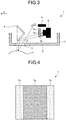
- FIG. 3 is a diagram illustrating optical paths of the self-emitting light emitted from the oven wall surface and the reflected light from the oven wall surface due to the laser light when the imaging device 8 images the oven wall surface.
- the self-emitting light emitted from the oven wall surface and the reflected light from the oven wall surface due to the laser light are the same in that they enter the thermally-insulated protection box 3 through the window 2 provided in the thermally-insulated protection box 3 and are reflected from the imaging mirror 6, and, thereafter, are transmitted through the optical filter 7 and enter the imaging device 8.
- the self-emitting light and the reflected light are transmitted through different regions of the optical filter 7.
- the reflected light is transmitted through a reflected light transmission region 7a of the optical filter 7 and the self-emitting light is transmitted through a self-emitting light transmission region 7b of the optical filter 7.
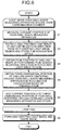
- FIG. 4 is a schematic diagram of the enlarged optical filter 7.
- the reflected light transmission region 7a is a band-like region in the middle of the optical filter 7 and the self-emitting light transmission regions 7b are band-like regions that border both sides of the reflected light transmission region 7a.
- the reflected light transmission region 7a is a narrow bandpass filter through which the laser light wavelength of the slit laser light source 4 is transmitted and the self-emitting light transmission region 7b is a wide bandpass filter through which the self-emitting light from the oven wall is transmitted.
- the band-like region of the reflected light transmission region 7a in the optical filter 7 is configured as a band-like region parallel to the slit direction, i.e., in the vertical direction of the oven wall surface, so that the reflected light from the oven wall surface due to the laser light from the slit laser light source 4 is able to be transmitted therethrough.
- the band-like regions of the self-emitting light transmission regions 7b in the optical filter 7 are band-like regions that border both sides of the reflected light transmission region 7a and are therefore necessarily configured as band-like regions parallel to the slit direction.
- condition A which is that the brightness of the reflected light due to the laser light is larger than the brightness of the self-emitting light from the oven wall.
- the optical filter 7 having a single wavelength characteristic is used for the oven wall shape measuring apparatus 1, it is difficult to adjust the output of the slit laser light source 4 so as to satisfy condition A. Therefore, in the oven wall shape measuring apparatus 1, regions with different wavelength characteristics are generated in the optical filter 7; therefore, the brightness of the reflected light due to the laser light is controlled so as to be always larger than the brightness of the self-emitting light from the oven wall in the range in which the laser light is imaged.
- FIG. 5 illustrates in a comparative manner part of an image inside the coke oven captured by the imaging device 8 and a graph obtained by averaging and quantifying the brightness distribution of the part of the image in the vertical direction along the lateral direction.
- the image in the upper part in FIG. 5 is an image obtained by cutting out the left half of the image corresponding to the left-side oven wall from one image inside the coke oven captured by the imaging device 8 and thereafter cutting out part thereof in the longitudinal direction, and is a region in which the self-emitting light emitted from the left-side oven wall surface and the slit-like laser light reflected from the left-side oven wall are included.
- the brightness of the image illustrated in FIG. 5 is obtained with 256 gray levels and the values (i.e., longitudinal axis) in the graph obtained by averaging and quantifying the brightness in the vertical direction of the image also has 256 gray levels.
- a portion near the left end of the image in the upper part in FIG. 5 (the positions between 0 and 50 pixels in the lateral direction) and the remaining region (the positions between 50 and 150 pixels in the lateral direction) are obtained by imaging light beams obtained via the self-emitting light transmission region 7b of the optical filter 7 and the reflected light transmission region 7a of the optical filter 7, respectively.
- an image of the light beam obtained via the reflected light transmission region 7a of the optical filter 7 is referred to as a reflected light image and an image of the light beam obtained via the self-emitting light transmission region 7b is referred to as a self-emitting light image.
- a region corresponding to the reflected light image in the image in the upper part in FIG. 5 is referred to as a reflected light image region and a region corresponding to the self-emitting light image is referred to as a self-emitting light image region.
- the peak brightness of the laser light and the brightness of the self-emitting light are the same level in the self-emitting light image region near the left side, the brightness of the reflected light due to the laser light becomes greater than the brightness of the self-emitting light from the oven wall in the reflected light image region on the right side.
- the optical filter 7 includes the reflected light transmission region 7a and the self-emitting light transmission region 7b, the reflected light due to the laser light and the self-emitting light from the oven wall do not mutually cause halation and the reflected light and the self-emitting light can be obtained at the same time.
- the procedure for combining the self-emitting light image and the shape image of the oven wall from an image represented by FIG. 5 will be described with reference to the flowchart in FIG. 6 .
- FIG. 6 is a flowchart illustrating a method of combining the self-emitting light image and the shape image of the oven wall that forms part of the oven wall shape measuring method according to the embodiment of the present invention.
- the method of combining the self-emitting light image and the shape image of the oven wall is composed of performing a loop of the following process at each position by moving the oven wall shape measuring apparatus 1 in the coke oven carbonization chamber.
- the above-described loop starts (Step S1).
- the current position X of the oven wall shape measuring apparatus 1 is measured by a position detecting unit that detects the position of the oven wall shape measuring apparatus 1 and is additionally provided in the oven wall shape measuring system in which the oven wall shape measuring apparatus 1 is used.
- the position detecting unit that detects the position of the oven wall shape measuring apparatus 1 can be realized by a method for measuring the rotation of a drive motor that drives the oven wall shape measuring apparatus 1 by a PLG or the like, a method in which a laser rangefinder using a time-of-flight method is used, or the like.
- one line in the vertical direction near the left end in the self-emitting light image region is extracted as a self-emitting light part at the time of imaging and is stored in a storing unit in association with the current position X of the oven wall shape measuring apparatus 1 (Step S2).
- the storing unit in Step S2 can be realized by a memory included in an image processing unit of the oven wall shape measuring system.
- One vertical line in the self-emitting light image region i.e., one line in the vertical direction of the oven wall, can be arbitrarily selected within a range in which halation does not occur and the self-emitting light has an appropriate intensity.
- Step S3 the peak position of the laser light obtained by performing the process in Step S3 is determined on the basis of the positional relationship between the imaging device and the laser light, and the peak position can be converted to a three-dimensional position centering around the oven wall shape measuring apparatus 1 by using a typical reconstruction calculation on the basis of the principle of triangulation (see FIG. 2 ) (Step S4).
- the current position X of the oven wall shape measuring apparatus 1 is added to the three-dimensional position of the one-line-shape obtained by the above process, which is stored as three-dimensional data on the oven wall shape corresponding to the position in the oven length direction in the coke oven carbonization chamber, i.e., the horizontal direction (Step S5).
- FIG. 7 is a diagram schematically representing one-line data of the self-emitting light and the shape of the oven wall obtained for each current position X of the oven wall shape measuring apparatus 1.
- the self-emitting light image and the shape image of the oven wall can be formed by arranging one-line data of the self-emitting light and the shape of the oven wall, which is obtained for each current position X of the oven wall shape measuring apparatus 1, with respect to the current position X of the oven wall shape measuring apparatus 1 (Step S6). Because the coke oven carbonization chamber has a certain height, all the self-emitting light images and the shape images of the oven wall in a height direction of the oven can be obtained by arranging oven wall shape measuring apparatuses 1 in the height direction and performing the measurement.
- FIG. 8 illustrates an image displaying the self-emitting light image of the oven wall bricks and the irregular shape of the oven wall imaged by using the oven wall shape measuring apparatus 1 in grayscale.
- the self-emitting light image in the upper section the brightness of the self-emitting light of the oven wall bricks is displayed in grayscale
- the distance in the depth direction is displayed in grayscale.
- the image illustrated in FIG. 8 can be generated from the image (for example, the image illustrated in FIG. 5 ) obtained by the imaging device 8 of the oven wall shape measuring apparatus 1 and from the intra-oven position of the oven wall shape measuring apparatus 1.
- the oven wall shape measuring system in which the oven wall shape measuring apparatus 1 is used additionally includes a unit that measures the intra-oven position of the oven wall shape measuring apparatus 1 and the image processing unit that generates the self-emitting light image of the oven wall surface and the image of the irregular shape from the image obtained by the imaging device 8.
- the oven wall shape measuring apparatus 1 can obtain both the self-emitting light image and the irregular shape of the bricks at the same time.
- the oven wall shape measuring apparatus 1 includes the slit laser light source 4 that is arranged in the thermally-insulated protection box 3 that includes the slit-like window 2 and emits slit-like laser light, the laser light mirror 5 that reflects the laser light and irradiates an oven wall surface with the laser light via the window 2, the imaging mirror 6 that reflects reflected light from the oven wall surface due to irradiation of the laser light and self-emitting light emitted from the oven wall surface, which enter the thermally-insulated protection box 3 via the window 2, and the imaging device 8 that images via the optical filter 7 the self-emitting light and the reflected light that are reflected from the imaging mirror 6.
- the irradiation angle of the laser light can be made deep and the length of the optical path of the laser light can be kept long. Consequently, the measurable range in the direction perpendicular to the oven wall surface and the irradiation range of the laser light can be increased without increasing the size of the oven wall shape measuring apparatus 1.
- the optical filter 7 includes the reflected light transmission region 7a that has a narrow bandpass characteristic of transmitting therethrough a wavelength of the laser light and the self-emitting light transmission region 7b that has a wide bandpass characteristic of transmitting therethrough a wavelength of the self-emitting light. Therefore, halation does not occur even if the irregular shape and the self-emitting light of the oven wall are measured at the same time.
- the oven wall shape measuring system in which the oven wall shape measuring apparatus 1 is used includes a position detecting unit that detects a position of the oven wall shape measuring apparatus 1 and an image processing unit that generates a self-emitting light image of the oven wall surface and an image of an irregular shape from an image captured by the imaging device 8 of the oven wall shape measuring apparatus 1 and a position of the oven wall shape measuring apparatus 1. Therefore, the deterioration state of the oven can be recognized in a complex manner. While the deterioration state of the irregularity can be determined from the irregular shape image, the difference in thermal conduction for each brick and the surface state of the bricks can be determined from the self-emitting light image. The life of the oven can be prolonged by strategically repairing the oven on the basis of the above information.
- the image processing unit generates the self-emitting light image of the oven wall surface and the image of the irregular shape by sorting a one-dimensional self-emitting light line of one line in a vertical direction in an image region in which the self-emitting light is imaged and a one-dimensional irregular shape line obtained by calculating an irregular shape of one line in a vertical direction of an oven wall on a basis of a principle of triangulation from an image of the slit-like laser light in an image region in which the reflected light is imaged, with respect to an intra-oven position of the oven wall shape measuring apparatus 1 detected by the position detecting unit. Therefore, both the self-emitting light image and the irregular shape of the bricks of the oven wall can be obtained at the same time.
- the oven wall shape measuring system includes the oven wall shape measuring apparatus 1 that is capable of separately imaging reflected light of slit-like laser light emitted to an oven wall surface and self-emitting light emitted from the oven wall surface in one image, a position detecting unit that detects an intra-oven position of the oven wall shape measuring apparatus 1, and an image processing unit that generates a self-emitting light image of the oven wall surface and an image of an irregular shape from an image captured by the imaging device 8 of the oven wall shape measuring apparatus 1 and an intra-oven position of the oven wall shape measuring apparatus 1. Therefore, the deterioration state of the oven can be recognized in a complex manner.
- the deterioration state of the irregularity can be determined from the irregular shape image
- the difference in thermal conduction for each brick and the surface state of the bricks can be determined from the self-emitting light image.
- the life of the oven can be prolonged by strategically repairing the oven on the basis of the above information.
- the image processing unit generates the self-emitting light image of the oven wall surface and the image of the irregular shape by sorting a one-dimensional self-emitting light line of one line in a vertical direction in an image region in which the self-emitting light is imaged and a one-dimensional irregular shape line obtained by calculating an irregular shape of one line in a vertical direction of an oven wall on a basis of a principle of triangulation from an image of the slit-like laser light in an image region in which the reflected light is imaged, with respect to an intra-oven position of the oven wall shape measuring apparatus 1 detected by the position detecting unit. Therefore, both the self-emitting light image and the irregular shape of the bricks of the oven wall can be obtained at the same time.
- the oven wall shape measuring method includes a position detecting step of detecting an intra-oven position of the oven wall shape measuring apparatus 1 by a position detecting unit, an imaging step of separately imaging reflected light of slit-like laser light emitted to an oven wall surface and self-emitting light emitted from the oven wall surface in one image, by the oven wall shape measuring apparatus 1, a one-dimensional self-emitting light line extracting step of extracting a one-dimensional self-emitting light line of one line in a vertical direction in an image region in which the self-emitting light is imaged, by an image processing unit, an irregular shape calculating step of calculating a one-dimensional irregular shape line in a vertical direction of an oven wall on a basis of a principle of triangulation from an image of the slit-like laser light in an image region in which the reflected light is imaged, by the image processing unit, and an image generating step of generating a self-emitting light image of the oven wall
- the deterioration state of the oven can be recognized in a complex manner. While the deterioration state of the irregularity can be determined from the irregular shape image, the difference in thermal conduction for each brick and the surface state of the bricks can be determined from the self-emitting light image. The life of the oven can be prolonged by strategically repairing the oven on the basis of the above information.
- the image generating step includes generating the self-emitting light image of the oven wall surface and the image of the irregular shape by sorting the one-dimensional self-emitting light line extracted in the one-dimensional self-emitting light line extracting step and the one-dimensional irregular shape line extracted in the irregular shape calculating step with respect to an intra-oven position of the oven wall shape measuring apparatus 1 by the image processing unit. Therefore, both the self-emitting light image and the irregular shape of the bricks of the oven wall can be obtained at the same time.
Landscapes
- Engineering & Computer Science (AREA)
- Chemical & Material Sciences (AREA)
- Physics & Mathematics (AREA)
- General Physics & Mathematics (AREA)
- Mechanical Engineering (AREA)
- General Engineering & Computer Science (AREA)
- Oil, Petroleum & Natural Gas (AREA)
- Materials Engineering (AREA)
- Organic Chemistry (AREA)
- Computer Vision & Pattern Recognition (AREA)
- Health & Medical Sciences (AREA)
- Life Sciences & Earth Sciences (AREA)
- Analytical Chemistry (AREA)
- Biochemistry (AREA)
- General Health & Medical Sciences (AREA)
- Immunology (AREA)
- Pathology (AREA)
- Length Measuring Devices By Optical Means (AREA)
- Waste-Gas Treatment And Other Accessory Devices For Furnaces (AREA)
Claims (5)
- Système de mesure de forme de paroi de four pour mesurer une forme irrégulière d'une surface de paroi de four, le système comprenant un appareil de mesure de forme de paroi de four (1), une unité de détection de position configurée pour détecter une position intra-four (X) de l'appareil de mesure de forme de paroi de four (1), et une unité de traitement d'image configurée pour générer une image de lumière à auto-émission de la surface de paroi de four et une image de la forme irrégulière de la surface de paroi de four à partir d'une image capturée par un dispositif de formation d'image (8) de l'appareil de mesure de forme de paroi de four (1) et d'une position (X) de l'appareil de mesure de forme de paroi de four (1) ; dans lequel l'appareil de mesure de forme de paroi de four (1) comprend :une source de lumière laser semblable à une fente (4) qui est agencée dans un boîtier de protection isolé thermiquement (3) comportant une fenêtre semblable à une fente (2) et qui émet une lumière laser semblable à une fente ;un miroir de formation d'image (6) qui est configuré pour réfléchir la lumière réfléchie du fait du rayonnement de la lumière laser et de la lumière à auto-émission émise à partir de la surface de paroi de four, la lumière réfléchie et la lumière à auto-émission entrant dans le boîtier de protection thermiquement isolé (3) à travers la fenêtre (2) ; et dans lequel :le dispositif de formation d'image (8) est configuré pour former une image, par l'intermédiaire d'un filtre optique (7), de la lumière à auto-émission et de la lumière réfléchie qui sont réfléchies à partir du miroir de formation d'image (6) ;un miroir de lumière laser (5) est configuré pour réfléchir la lumière laser et est configuré pour irradier une surface de paroi de four avec la lumière laser à travers la fenêtre (2) ; etle filtre optique (7), interposé entre le miroir de formation d'image (6) et le dispositif de formation d'image (8), comporte une première région de transmission (7a) ayant les caractéristiques passe-bande d'une bande étroite et transmettant à travers celle-ci une longueur d'onde de la lumière laser, et une deuxième région de transmission (7b) ayant les caractéristiques passe-bande d'une large bande et transmettant à travers celle-ci une longueur d'onde de la lumière à auto-émission, la première région de transmission et la deuxième région de transmission étant configurées en tant que régions similaires à des bandes parallèles à la direction de fente ; le système est configuré pourdétecter, par l'unité de détection de position, une position intra-four (X) de l'appareil de mesure de forme de paroi de four (1) ;
former séparément une image, en utilisant le filtre optique (7) de l'appareil de mesure de forme de paroi de four (1), dans une image, de la lumière réfléchie de la lumière laser semblable à une fente rayonnée vers la surface de paroi de four et de la lumière à auto-émission émise à partir de la surface de paroi de four ;
extraire, par l'unité de traitement d'image, une ligne de lumière à auto-émission unidimensionnelle d'une ligne dans une direction verticale dans une région d'image de laquelle une image de la lumière à auto-émission a été formée ;
obtenir, par l'unité de traitement d'image, la forme de la paroi de four en calculant une ligne de forme irrégulière unidimensionnelle dans une direction verticale de la paroi de four sur la base d'un principe de triangulation à partir d'une image de la lumière laser similaire à une fente dans une région d'image de laquelle une image de la lumière réfléchie a été formée ; et
générer, par l'unité de traitement d'image, une image de lumière à auto-émission de la surface de paroi de four et une image d'une forme irrégulière de la surface de paroi de four en utilisant la position intra-four (X) de l'appareil de mesure de forme de paroi de four (1) détectée par l'unité de détection de position, la ligne de lumière à auto-émission unidimensionnelle extraite par l'unité de traitement d'image, et la ligne de forme irrégulière unidimensionnelle calculée par l'unité de traitement d'image. - Système de mesure de forme de paroi de four selon la revendication 1, dans lequel
un axe optique de la lumière laser émise à partir de la source de lumière laser semblable à une fente (4) est agencé parallèlement à une surface longitudinale du boîtier de protection isolé thermiquement (3), et
un angle d'incidence (φ) de la lumière laser par rapport au miroir de lumière laser (5) est inférieur ou égal à 60 degrés. - Système de mesure de forme de paroi de four selon la revendication 1 ou 2, dans lequel l'unité de traitement d'image est configurée pour générer l'image de lumière à auto-émission de la surface de paroi de four et l'image de la forme irrégulière de la surface de paroi de four en agençant, par rapport à la position intra-four (X) de l'appareil de mesure de forme de paroi de four détectée par l'unité de détection de position :
une ligne de lumière à auto-émission unidimensionnelle d'une ligne dans une direction verticale dans une région d'image de laquelle une image de la lumière à auto-émission a été formée ; et
une ligne de forme irrégulière unidimensionnelle de la forme de la paroi de four obtenue en calculant une forme irrégulière d'une ligne dans la direction verticale de la paroi de four sur la base d'un principe de triangulation à partir d'une image de la lumière laser semblable à une fente dans une région d'image de laquelle une image de la lumière réfléchie a été formée. - Procédé de mesure de forme de paroi de four pour mesurer une forme irrégulière d'une surface de paroi de four en utilisant le système de mesure de forme de paroi de four selon la revendication 1, le procédé comprenant :une étape de détection de position, par l'unité de détection de position, pour détecter une position intra-four (X) de l'appareil de mesure de forme de paroi de four (1) ;une étape de formation d'image, en utilisant le filtre optique (7) de l'appareil de mesure de forme de paroi de four (1), pour former séparément une image, dans une image, de la lumière réfléchie de la lumière laser semblable à une fente rayonnée vers la surface de paroi de four et de la lumière à auto-émission émise à partir de la surface de paroi de four ;une étape d'extraction de ligne de lumière à auto-émission unidimensionnelle, par l'unité de traitement d'image, pour extraire une ligne de lumière à auto-émission unidimensionnelle d'une ligne dans une direction verticale dans une région d'image de laquelle une image de la lumière à auto-émission a été formée ;une étape de calcul de forme irrégulière, par l'unité de traitement d'image, pour obtenir la forme de la paroi de four en calculant une ligne de forme irrégulière unidimensionnelle dans une direction verticale de la paroi de four sur la base d'un principe de triangulation à partir d'une image de la lumière laser semblable à une fente dans une région d'image de laquelle une image de la lumière réfléchie a été formée ; etune étape de génération d'image, par l'unité de traitement d'image, pour générer une image de lumière à auto-émission de la surface de paroi de four et une image d'une forme irrégulière de la surface de paroi de four en utilisant la position intra-four (X) de l'appareil de mesure de forme de paroi de four (1) détectée à l'étape de détection de position, la ligne de lumière à 'auto-émission unidimensionnelle extraite à l'étape d'extraction de ligne de lumière à auto-émission unidimensionnelle, et la ligne de forme irrégulière unidimensionnelle extraite à l'étape de calcul de forme irrégulière.
- Procédé de mesure de forme de paroi de four selon la revendication 4, dans lequel l'étape de génération d'image comprend la génération, par l'unité de traitement d'image, de l'image de lumière à auto-émission de la surface de paroi de four et de l'image de la forme irrégulière de la surface de paroi de four en agençant, par rapport à une position intra-four (X) de l'appareil de mesure de forme de paroi de four :la ligne de lumière à auto-émission unidimensionnelle extraite à l'étape d'extraction de ligne de lumière à auto-émission unidimensionnelle ; etla ligne de forme irrégulière unidimensionnelle extraite à l'étape de calcul de forme irrégulière.
Applications Claiming Priority (3)
| Application Number | Priority Date | Filing Date | Title |
|---|---|---|---|
| JP2010291018 | 2010-12-27 | ||
| JP2011275631A JP6227220B2 (ja) | 2010-12-27 | 2011-12-16 | 炉壁形状測定装置、炉壁形状測定システム、および炉壁形状測定方法 |
| PCT/JP2011/079352 WO2012090758A1 (fr) | 2010-12-27 | 2011-12-19 | Dispositif de mesure de forme de paroi de four, système de mesure de forme de paroi de four et procédé de mesure de forme de paroi de four |
Publications (3)
| Publication Number | Publication Date |
|---|---|
| EP2660558A1 EP2660558A1 (fr) | 2013-11-06 |
| EP2660558A4 EP2660558A4 (fr) | 2017-01-25 |
| EP2660558B1 true EP2660558B1 (fr) | 2019-02-20 |
Family
ID=46382869
Family Applications (1)
| Application Number | Title | Priority Date | Filing Date |
|---|---|---|---|
| EP11852692.0A Active EP2660558B1 (fr) | 2010-12-27 | 2011-12-19 | Dispositif de mesure de forme de paroi de four, système de mesure de forme de paroi de four et procédé de mesure de forme de paroi de four |
Country Status (7)
| Country | Link |
|---|---|
| US (1) | US9638516B2 (fr) |
| EP (1) | EP2660558B1 (fr) |
| JP (1) | JP6227220B2 (fr) |
| KR (1) | KR101497253B1 (fr) |
| CN (1) | CN103282739B (fr) |
| TW (1) | TWI570379B (fr) |
| WO (1) | WO2012090758A1 (fr) |
Families Citing this family (11)
| Publication number | Priority date | Publication date | Assignee | Title |
|---|---|---|---|---|
| NL2013192B1 (en) * | 2014-07-15 | 2016-07-14 | Cobra Carbon Grinding B V | Apparatus and method for grinding carbonaceous materials. |
| WO2017195001A1 (fr) * | 2016-05-13 | 2017-11-16 | Arcelormittal | Procédé d'obtention de la hauteur d'un matériau empilé dans un four à coke |
| WO2018002683A1 (fr) * | 2016-06-30 | 2018-01-04 | Centre De Pyrolyse Du Charbon De Marienau | Dispositif de mesure d'une forme d'une partie de paroi d'un four, tel qu'un four à coke |
| JP6848304B2 (ja) * | 2016-09-28 | 2021-03-24 | 日本製鉄株式会社 | コークス炉の炭化室の壁面測定方法及び壁面測定装置 |
| CN108534712A (zh) * | 2018-06-16 | 2018-09-14 | 复旦大学 | 一种柱面面形干涉检测装置 |
| KR102069775B1 (ko) | 2018-08-20 | 2020-01-23 | (주)에코도 | 코르크를 주재로 하는 투수 및 탄성 바닥포장재 및 이를 이용한 바닥 포장방법 |
| FI3987247T3 (fi) * | 2019-06-18 | 2024-03-01 | Process Metrix Llc | Järjestelmä, laite ja menetelmä astian sisäisen tulenkestävän vuorauksen mittaamiseksi |
| CN111982005A (zh) * | 2020-09-16 | 2020-11-24 | 北京强度环境研究所 | 一种三维变形场测量装置 |
| CN112729165A (zh) * | 2020-12-21 | 2021-04-30 | 江苏烽禾升智能科技有限公司 | 一种基于机械视觉的三维扫描系统及测试方法 |
| CN114525144B (zh) * | 2021-09-10 | 2024-07-19 | 上海梅山钢铁股份有限公司 | 一种实现推焦车推焦杆准确对中装置 |
| CN120760601B (zh) * | 2025-09-08 | 2025-11-25 | 西安汇腾航空科技有限公司 | 一种陶瓷基隔热板生产用检测装置 |
Family Cites Families (19)
| Publication number | Priority date | Publication date | Assignee | Title |
|---|---|---|---|---|
| SE414347B (sv) | 1974-11-20 | 1980-07-21 | Aga Ab | Anordning for att meta avstandet till en punkt pa den egenstralande innerveggen i en ugn |
| US4708482A (en) * | 1982-02-22 | 1987-11-24 | Armco Inc. | Method and apparatus for measuring wear in the lining of refractory furnaces |
| JPH0454208Y2 (fr) * | 1987-03-17 | 1992-12-18 | ||
| JPH0718332B2 (ja) * | 1990-06-22 | 1995-03-01 | 株式会社クボタ | エンジンの排気ガス中の煤塵分離装置 |
| JPH0791931A (ja) * | 1993-09-24 | 1995-04-07 | Matsushita Electric Ind Co Ltd | パターン検出方法およびパターン検出装置 |
| JP2799291B2 (ja) * | 1994-06-07 | 1998-09-17 | 動力炉・核燃料開発事業団 | 炉内検査装置 |
| JP3042758B2 (ja) * | 1995-02-17 | 2000-05-22 | 川崎製鉄株式会社 | コークス炉炭化室の炉壁診断方法および装置 |
| DE19520187C1 (de) * | 1995-06-01 | 1996-09-12 | Microlas Lasersystem Gmbh | Optik zum Herstellen einer scharfen Beleuchtungslinie aus einem Laserstrahl |
| DE19604075C2 (de) | 1996-02-05 | 1998-02-19 | F & O Electronic Systems | Vorrichtung zur Inspektion der Oberfläche von Holz zwecks Feststellung von Oberflächenmerkmalen und Verfahren hierzu |
| JP3962173B2 (ja) | 1999-03-16 | 2007-08-22 | 新日本製鐵株式会社 | コークス炉壁面観察装置 |
| NO20004855L (no) | 1999-09-30 | 2001-04-02 | Sony Corp | Fast elektrolyttcelle |
| JP3965032B2 (ja) * | 2000-11-14 | 2007-08-22 | 新日本製鐵株式会社 | コークス炉炭化室炉幅測定装置 |
| JP4133106B2 (ja) * | 2002-08-19 | 2008-08-13 | 新日本製鐵株式会社 | 炉壁形状測定装置 |
| KR100615106B1 (ko) | 2002-01-09 | 2006-08-25 | 신닛뽄세이테쯔 카부시키카이샤 | 노벽 관찰 및 노벽 형상 측정장치 |
| US7355768B1 (en) * | 2004-08-14 | 2008-04-08 | Billmers Richard I | Wavelength tunable holographic filter with broad acceptance angle and narrow spectral bandwidth |
| EP1655570B1 (fr) | 2004-11-08 | 2011-05-18 | Matthias Franke | Procédé destiné à la mesure géométrique optique d'une cavité dans une installation de traitement thermique |
| JP4888127B2 (ja) * | 2007-01-17 | 2012-02-29 | コニカミノルタセンシング株式会社 | 三次元測定装置及び携帯型計測器 |
| JP4262281B2 (ja) * | 2007-02-22 | 2009-05-13 | 新日本製鐵株式会社 | コークス炉の壁面評価装置、コークス炉の壁面評価方法、及びコンピュータプログラム |
| JP4516627B2 (ja) | 2008-11-10 | 2010-08-04 | 株式会社Ihi検査計測 | 炉内観察装置および炉内観察方法 |
-
2011
- 2011-12-16 JP JP2011275631A patent/JP6227220B2/ja active Active
- 2011-12-19 US US13/997,987 patent/US9638516B2/en not_active Expired - Fee Related
- 2011-12-19 KR KR1020137016594A patent/KR101497253B1/ko not_active Expired - Fee Related
- 2011-12-19 WO PCT/JP2011/079352 patent/WO2012090758A1/fr not_active Ceased
- 2011-12-19 CN CN201180062802.XA patent/CN103282739B/zh not_active Expired - Fee Related
- 2011-12-19 EP EP11852692.0A patent/EP2660558B1/fr active Active
- 2011-12-27 TW TW100148947A patent/TWI570379B/zh not_active IP Right Cessation
Non-Patent Citations (1)
| Title |
|---|
| None * |
Also Published As
| Publication number | Publication date |
|---|---|
| TWI570379B (zh) | 2017-02-11 |
| KR20130114189A (ko) | 2013-10-16 |
| TW201241387A (en) | 2012-10-16 |
| JP2012150103A (ja) | 2012-08-09 |
| US9638516B2 (en) | 2017-05-02 |
| US20130286406A1 (en) | 2013-10-31 |
| JP6227220B2 (ja) | 2017-11-08 |
| CN103282739A (zh) | 2013-09-04 |
| CN103282739B (zh) | 2016-11-09 |
| WO2012090758A1 (fr) | 2012-07-05 |
| EP2660558A4 (fr) | 2017-01-25 |
| EP2660558A1 (fr) | 2013-11-06 |
| KR101497253B1 (ko) | 2015-02-27 |
Similar Documents
| Publication | Publication Date | Title |
|---|---|---|
| EP2660558B1 (fr) | Dispositif de mesure de forme de paroi de four, système de mesure de forme de paroi de four et procédé de mesure de forme de paroi de four | |
| KR102156686B1 (ko) | 레이저 용접에서 고온 균열들의 검출 | |
| WO2020185169A1 (fr) | Système de surveillance et procédé d'identification d'anomalies dans un processus d'impression 3d | |
| EP4026647B1 (fr) | Dispositif d'usinage laser, et procédé d'usinage laser | |
| JP2010164463A (ja) | レーザ3次元画像計測装置 | |
| JP5202936B2 (ja) | 走査型顕微鏡 | |
| JP2015194418A (ja) | 構造物の表面検査装置および表面検査方法 | |
| US20090323082A1 (en) | Optical Profile Scanning | |
| JP5676228B2 (ja) | コークス炉炉内監視方法および炉壁管理方法並びに監視システム | |
| JP2007315803A (ja) | 表面検査装置 | |
| JP5611177B2 (ja) | 溶削異常検出装置および溶削異常検出方法 | |
| JP2021067588A (ja) | 被検査体の表面検査装置および被検査体の表面検査方法 | |
| JP4362391B2 (ja) | 炉壁形状測定方法及び炉壁形状測定装置 | |
| JP2021003813A (ja) | 付加製造物の品質推定装置 | |
| JP2012194108A (ja) | 被計測体の表面異常識別装置 | |
| JP2020002320A (ja) | コークス炉とコークス炉のドアフレームの診断装置および診断システム | |
| JP6480171B2 (ja) | X線検査装置 | |
| JP6457854B2 (ja) | X線検査装置 | |
| JP2006214867A (ja) | 欠陥粒子測定装置および欠陥粒子測定方法 | |
| WO2021261105A1 (fr) | Dispositif de mesure, machine à cintrer et procédé de mesure | |
| KR101024932B1 (ko) | 결함 검출 장치 | |
| JP5589894B2 (ja) | 形状測定方法 | |
| JP2019147884A (ja) | 作業位置検出装置 | |
| JPS63191005A (ja) | コ−クス炉の炭化室幅測定方法及び装置 | |
| KR20140006608A (ko) | 절단 정반의 유지보수 정보 제공 방법 및 장치 |
Legal Events
| Date | Code | Title | Description |
|---|---|---|---|
| PUAI | Public reference made under article 153(3) epc to a published international application that has entered the european phase |
Free format text: ORIGINAL CODE: 0009012 |
|
| 17P | Request for examination filed |
Effective date: 20130722 |
|
| AK | Designated contracting states |
Kind code of ref document: A1 Designated state(s): AL AT BE BG CH CY CZ DE DK EE ES FI FR GB GR HR HU IE IS IT LI LT LU LV MC MK MT NL NO PL PT RO RS SE SI SK SM TR |
|
| DAX | Request for extension of the european patent (deleted) | ||
| RA4 | Supplementary search report drawn up and despatched (corrected) |
Effective date: 20170104 |
|
| RIC1 | Information provided on ipc code assigned before grant |
Ipc: G01N 21/954 20060101ALI20161222BHEP Ipc: G01B 11/25 20060101AFI20161222BHEP Ipc: F27D 21/00 20060101ALI20161222BHEP Ipc: C10B 45/00 20060101ALI20161222BHEP |
|
| STAA | Information on the status of an ep patent application or granted ep patent |
Free format text: STATUS: EXAMINATION IS IN PROGRESS |
|
| 17Q | First examination report despatched |
Effective date: 20180212 |
|
| GRAP | Despatch of communication of intention to grant a patent |
Free format text: ORIGINAL CODE: EPIDOSNIGR1 |
|
| STAA | Information on the status of an ep patent application or granted ep patent |
Free format text: STATUS: GRANT OF PATENT IS INTENDED |
|
| INTG | Intention to grant announced |
Effective date: 20180824 |
|
| GRAS | Grant fee paid |
Free format text: ORIGINAL CODE: EPIDOSNIGR3 |
|
| GRAA | (expected) grant |
Free format text: ORIGINAL CODE: 0009210 |
|
| STAA | Information on the status of an ep patent application or granted ep patent |
Free format text: STATUS: THE PATENT HAS BEEN GRANTED |
|
| AK | Designated contracting states |
Kind code of ref document: B1 Designated state(s): AL AT BE BG CH CY CZ DE DK EE ES FI FR GB GR HR HU IE IS IT LI LT LU LV MC MK MT NL NO PL PT RO RS SE SI SK SM TR |
|
| REG | Reference to a national code |
Ref country code: GB Ref legal event code: FG4D |
|
| REG | Reference to a national code |
Ref country code: CH Ref legal event code: EP |
|
| REG | Reference to a national code |
Ref country code: DE Ref legal event code: R096 Ref document number: 602011056477 Country of ref document: DE |
|
| REG | Reference to a national code |
Ref country code: AT Ref legal event code: REF Ref document number: 1098771 Country of ref document: AT Kind code of ref document: T Effective date: 20190315 |
|
| REG | Reference to a national code |
Ref country code: IE Ref legal event code: FG4D |
|
| REG | Reference to a national code |
Ref country code: NL Ref legal event code: MP Effective date: 20190220 |
|
| REG | Reference to a national code |
Ref country code: LT Ref legal event code: MG4D |
|
| PG25 | Lapsed in a contracting state [announced via postgrant information from national office to epo] |
Ref country code: SE Free format text: LAPSE BECAUSE OF FAILURE TO SUBMIT A TRANSLATION OF THE DESCRIPTION OR TO PAY THE FEE WITHIN THE PRESCRIBED TIME-LIMIT Effective date: 20190220 Ref country code: PT Free format text: LAPSE BECAUSE OF FAILURE TO SUBMIT A TRANSLATION OF THE DESCRIPTION OR TO PAY THE FEE WITHIN THE PRESCRIBED TIME-LIMIT Effective date: 20190620 Ref country code: FI Free format text: LAPSE BECAUSE OF FAILURE TO SUBMIT A TRANSLATION OF THE DESCRIPTION OR TO PAY THE FEE WITHIN THE PRESCRIBED TIME-LIMIT Effective date: 20190220 Ref country code: NO Free format text: LAPSE BECAUSE OF FAILURE TO SUBMIT A TRANSLATION OF THE DESCRIPTION OR TO PAY THE FEE WITHIN THE PRESCRIBED TIME-LIMIT Effective date: 20190520 Ref country code: LT Free format text: LAPSE BECAUSE OF FAILURE TO SUBMIT A TRANSLATION OF THE DESCRIPTION OR TO PAY THE FEE WITHIN THE PRESCRIBED TIME-LIMIT Effective date: 20190220 |
|
| PG25 | Lapsed in a contracting state [announced via postgrant information from national office to epo] |
Ref country code: IS Free format text: LAPSE BECAUSE OF FAILURE TO SUBMIT A TRANSLATION OF THE DESCRIPTION OR TO PAY THE FEE WITHIN THE PRESCRIBED TIME-LIMIT Effective date: 20190620 Ref country code: GR Free format text: LAPSE BECAUSE OF FAILURE TO SUBMIT A TRANSLATION OF THE DESCRIPTION OR TO PAY THE FEE WITHIN THE PRESCRIBED TIME-LIMIT Effective date: 20190521 Ref country code: RS Free format text: LAPSE BECAUSE OF FAILURE TO SUBMIT A TRANSLATION OF THE DESCRIPTION OR TO PAY THE FEE WITHIN THE PRESCRIBED TIME-LIMIT Effective date: 20190220 Ref country code: NL Free format text: LAPSE BECAUSE OF FAILURE TO SUBMIT A TRANSLATION OF THE DESCRIPTION OR TO PAY THE FEE WITHIN THE PRESCRIBED TIME-LIMIT Effective date: 20190220 Ref country code: HR Free format text: LAPSE BECAUSE OF FAILURE TO SUBMIT A TRANSLATION OF THE DESCRIPTION OR TO PAY THE FEE WITHIN THE PRESCRIBED TIME-LIMIT Effective date: 20190220 Ref country code: LV Free format text: LAPSE BECAUSE OF FAILURE TO SUBMIT A TRANSLATION OF THE DESCRIPTION OR TO PAY THE FEE WITHIN THE PRESCRIBED TIME-LIMIT Effective date: 20190220 Ref country code: BG Free format text: LAPSE BECAUSE OF FAILURE TO SUBMIT A TRANSLATION OF THE DESCRIPTION OR TO PAY THE FEE WITHIN THE PRESCRIBED TIME-LIMIT Effective date: 20190520 |
|
| REG | Reference to a national code |
Ref country code: AT Ref legal event code: MK05 Ref document number: 1098771 Country of ref document: AT Kind code of ref document: T Effective date: 20190220 |
|
| PG25 | Lapsed in a contracting state [announced via postgrant information from national office to epo] |
Ref country code: CZ Free format text: LAPSE BECAUSE OF FAILURE TO SUBMIT A TRANSLATION OF THE DESCRIPTION OR TO PAY THE FEE WITHIN THE PRESCRIBED TIME-LIMIT Effective date: 20190220 Ref country code: ES Free format text: LAPSE BECAUSE OF FAILURE TO SUBMIT A TRANSLATION OF THE DESCRIPTION OR TO PAY THE FEE WITHIN THE PRESCRIBED TIME-LIMIT Effective date: 20190220 Ref country code: IT Free format text: LAPSE BECAUSE OF FAILURE TO SUBMIT A TRANSLATION OF THE DESCRIPTION OR TO PAY THE FEE WITHIN THE PRESCRIBED TIME-LIMIT Effective date: 20190220 Ref country code: RO Free format text: LAPSE BECAUSE OF FAILURE TO SUBMIT A TRANSLATION OF THE DESCRIPTION OR TO PAY THE FEE WITHIN THE PRESCRIBED TIME-LIMIT Effective date: 20190220 Ref country code: EE Free format text: LAPSE BECAUSE OF FAILURE TO SUBMIT A TRANSLATION OF THE DESCRIPTION OR TO PAY THE FEE WITHIN THE PRESCRIBED TIME-LIMIT Effective date: 20190220 Ref country code: DK Free format text: LAPSE BECAUSE OF FAILURE TO SUBMIT A TRANSLATION OF THE DESCRIPTION OR TO PAY THE FEE WITHIN THE PRESCRIBED TIME-LIMIT Effective date: 20190220 Ref country code: SK Free format text: LAPSE BECAUSE OF FAILURE TO SUBMIT A TRANSLATION OF THE DESCRIPTION OR TO PAY THE FEE WITHIN THE PRESCRIBED TIME-LIMIT Effective date: 20190220 Ref country code: AL Free format text: LAPSE BECAUSE OF FAILURE TO SUBMIT A TRANSLATION OF THE DESCRIPTION OR TO PAY THE FEE WITHIN THE PRESCRIBED TIME-LIMIT Effective date: 20190220 |
|
| REG | Reference to a national code |
Ref country code: DE Ref legal event code: R097 Ref document number: 602011056477 Country of ref document: DE |
|
| PG25 | Lapsed in a contracting state [announced via postgrant information from national office to epo] |
Ref country code: PL Free format text: LAPSE BECAUSE OF FAILURE TO SUBMIT A TRANSLATION OF THE DESCRIPTION OR TO PAY THE FEE WITHIN THE PRESCRIBED TIME-LIMIT Effective date: 20190220 Ref country code: SM Free format text: LAPSE BECAUSE OF FAILURE TO SUBMIT A TRANSLATION OF THE DESCRIPTION OR TO PAY THE FEE WITHIN THE PRESCRIBED TIME-LIMIT Effective date: 20190220 |
|
| PLBE | No opposition filed within time limit |
Free format text: ORIGINAL CODE: 0009261 |
|
| STAA | Information on the status of an ep patent application or granted ep patent |
Free format text: STATUS: NO OPPOSITION FILED WITHIN TIME LIMIT |
|
| PG25 | Lapsed in a contracting state [announced via postgrant information from national office to epo] |
Ref country code: AT Free format text: LAPSE BECAUSE OF FAILURE TO SUBMIT A TRANSLATION OF THE DESCRIPTION OR TO PAY THE FEE WITHIN THE PRESCRIBED TIME-LIMIT Effective date: 20190220 |
|
| 26N | No opposition filed |
Effective date: 20191121 |
|
| PG25 | Lapsed in a contracting state [announced via postgrant information from national office to epo] |
Ref country code: SI Free format text: LAPSE BECAUSE OF FAILURE TO SUBMIT A TRANSLATION OF THE DESCRIPTION OR TO PAY THE FEE WITHIN THE PRESCRIBED TIME-LIMIT Effective date: 20190220 |
|
| PG25 | Lapsed in a contracting state [announced via postgrant information from national office to epo] |
Ref country code: TR Free format text: LAPSE BECAUSE OF FAILURE TO SUBMIT A TRANSLATION OF THE DESCRIPTION OR TO PAY THE FEE WITHIN THE PRESCRIBED TIME-LIMIT Effective date: 20190220 |
|
| REG | Reference to a national code |
Ref country code: CH Ref legal event code: PL |
|
| REG | Reference to a national code |
Ref country code: BE Ref legal event code: MM Effective date: 20191231 |
|
| PG25 | Lapsed in a contracting state [announced via postgrant information from national office to epo] |
Ref country code: MC Free format text: LAPSE BECAUSE OF FAILURE TO SUBMIT A TRANSLATION OF THE DESCRIPTION OR TO PAY THE FEE WITHIN THE PRESCRIBED TIME-LIMIT Effective date: 20190220 |
|
| GBPC | Gb: european patent ceased through non-payment of renewal fee |
Effective date: 20191219 |
|
| PG25 | Lapsed in a contracting state [announced via postgrant information from national office to epo] |
Ref country code: IE Free format text: LAPSE BECAUSE OF NON-PAYMENT OF DUE FEES Effective date: 20191219 Ref country code: GB Free format text: LAPSE BECAUSE OF NON-PAYMENT OF DUE FEES Effective date: 20191219 Ref country code: LU Free format text: LAPSE BECAUSE OF NON-PAYMENT OF DUE FEES Effective date: 20191219 Ref country code: FR Free format text: LAPSE BECAUSE OF NON-PAYMENT OF DUE FEES Effective date: 20191231 |
|
| PG25 | Lapsed in a contracting state [announced via postgrant information from national office to epo] |
Ref country code: CH Free format text: LAPSE BECAUSE OF NON-PAYMENT OF DUE FEES Effective date: 20191231 Ref country code: BE Free format text: LAPSE BECAUSE OF NON-PAYMENT OF DUE FEES Effective date: 20191231 Ref country code: LI Free format text: LAPSE BECAUSE OF NON-PAYMENT OF DUE FEES Effective date: 20191231 |
|
| REG | Reference to a national code |
Ref country code: DE Ref legal event code: R082 Ref document number: 602011056477 Country of ref document: DE Representative=s name: HL KEMPNER PATENTANWAELTE, SOLICITORS (ENGLAND, DE Ref country code: DE Ref legal event code: R082 Ref document number: 602011056477 Country of ref document: DE Representative=s name: HL KEMPNER PATENTANWALT, RECHTSANWALT, SOLICIT, DE Ref country code: DE Ref legal event code: R082 Ref document number: 602011056477 Country of ref document: DE Representative=s name: HL KEMPNER PARTG MBB, DE |
|
| PG25 | Lapsed in a contracting state [announced via postgrant information from national office to epo] |
Ref country code: CY Free format text: LAPSE BECAUSE OF FAILURE TO SUBMIT A TRANSLATION OF THE DESCRIPTION OR TO PAY THE FEE WITHIN THE PRESCRIBED TIME-LIMIT Effective date: 20190220 |
|
| PG25 | Lapsed in a contracting state [announced via postgrant information from national office to epo] |
Ref country code: HU Free format text: LAPSE BECAUSE OF FAILURE TO SUBMIT A TRANSLATION OF THE DESCRIPTION OR TO PAY THE FEE WITHIN THE PRESCRIBED TIME-LIMIT; INVALID AB INITIO Effective date: 20111219 Ref country code: MT Free format text: LAPSE BECAUSE OF FAILURE TO SUBMIT A TRANSLATION OF THE DESCRIPTION OR TO PAY THE FEE WITHIN THE PRESCRIBED TIME-LIMIT Effective date: 20190220 |
|
| PG25 | Lapsed in a contracting state [announced via postgrant information from national office to epo] |
Ref country code: MK Free format text: LAPSE BECAUSE OF FAILURE TO SUBMIT A TRANSLATION OF THE DESCRIPTION OR TO PAY THE FEE WITHIN THE PRESCRIBED TIME-LIMIT Effective date: 20190220 |
|
| PGFP | Annual fee paid to national office [announced via postgrant information from national office to epo] |
Ref country code: DE Payment date: 20251028 Year of fee payment: 15 |