EP2660661A2 - Freier Hemmungsmechanismus für Uhrwerk, Uhrwerk und/oder Uhr, das/die diesen Hemmungsmechanismus umfasst - Google Patents
Freier Hemmungsmechanismus für Uhrwerk, Uhrwerk und/oder Uhr, das/die diesen Hemmungsmechanismus umfasst Download PDFInfo
- Publication number
- EP2660661A2 EP2660661A2 EP13002120.7A EP13002120A EP2660661A2 EP 2660661 A2 EP2660661 A2 EP 2660661A2 EP 13002120 A EP13002120 A EP 13002120A EP 2660661 A2 EP2660661 A2 EP 2660661A2
- Authority
- EP
- European Patent Office
- Prior art keywords
- wheel
- pulse
- exhaust mechanism
- spring
- mechanism according
- Prior art date
- Legal status (The legal status is an assumption and is not a legal conclusion. Google has not performed a legal analysis and makes no representation as to the accuracy of the status listed.)
- Granted
Links
Images






Classifications
-
- G—PHYSICS
- G04—HOROLOGY
- G04B—MECHANICALLY-DRIVEN CLOCKS OR WATCHES; MECHANICAL PARTS OF CLOCKS OR WATCHES IN GENERAL; TIME PIECES USING THE POSITION OF THE SUN, MOON OR STARS
- G04B15/00—Escapements
- G04B15/06—Free escapements
-
- G—PHYSICS
- G04—HOROLOGY
- G04B—MECHANICALLY-DRIVEN CLOCKS OR WATCHES; MECHANICAL PARTS OF CLOCKS OR WATCHES IN GENERAL; TIME PIECES USING THE POSITION OF THE SUN, MOON OR STARS
- G04B15/00—Escapements
- G04B15/14—Component parts or constructional details, e.g. construction of the lever or the escape wheel
Definitions
- the present invention relates to free escapement mechanisms for clockwork.
- Free exhausts are nowadays recognized as the best way for the maintenance of the oscillations of a system balance-spiral,
- Expansion exhausts are direct impulse exhausts.
- the trigger is a stop with only one rest position.
- the escape wheel gives a pulse per period to the oscillator without the need for an intermediate element. As a result, the wheel goes forward only once per period.
- a period of an oscillator consists of two alternations. Due to the lack of impulse during the silent phase, the expansion exhausts are not self-starting.
- Anchor escapements exist either with a direct impulse from the escapement wheel to the pendulum or indirectly by means of the anchor.
- the anchor is a stopping piece that has two resting positions. Anchor escapements advance the gear once in a row. The only exception is the lever escapement, or the escape wheel falls during the so-called "dumb" phase on a second resting surface. During this silent phase, the known bleed escapements can not transmit energy to the oscillator. The silent phase, even as it moves the wheel very little, aims to blow the seconds hand once per period of the oscillator.
- the object of the present invention is to provide a free escapement mechanism for a clockwork movement that can be controlled either by detents or by an anchor that is applicable to portable timepieces and transmits energy. oscillator at each alternation of it while reducing energy losses, reduce inertial influences and make the exhaust insensitive to shocks. Another goal is to reduce or eliminate energy-consuming falls.
- the invention also relates to a movement and / or timepiece incorporating such an exhaust mechanism.
- the present invention also aims at the realization of simple and easy to achieve relaxation.
- the invention therefore also relates to an expansion, particularly for an exhaust mechanism which is distinguished by the fact that it is monobloc that is to say made in one piece.
- the free escapement mechanism according to the invention is an escapement in which the escapement wheel makes only one step by oscillation of the balance wheel as in the blow-back exhaust mechanisms, with the difference that in the present mechanism the pendulum receives two impulses per oscillation, one alternately, which is not the case in a classic escapement.
- this embodiment of the free escape mechanism according to the invention is controlled by two detents. This is a preferred embodiment because it gives the best results in terms of energy and efficiency of the mechanism but it is obvious that in other embodiments this exhaust mechanism could be controlled. by other control means for example by an anchor. It should be noted, however, that in this case the anchor serves only to control the exhaust, that is to say that the anchor does not participate in the energy transmission of the escape wheel to the axis of the pendulum.
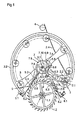
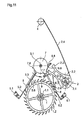
- the figure 1 illustrates in plan from above a general view of the free escape mechanism without being represented the other elements of the watch movement such as platinum and bridges, wheel etc. to avoid overloading the drawings and to facilitate understanding of the exhaust mechanism that constitutes the present invention.
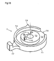
- the plate 7 is constituted in the illustrated example of a large plate 7.1 and a small plate 7.2 (see figure 18 ).
- the large plate 7.1 comprises a plate 7.3 comprising fixing means for example a hole to be driven on the balance shaft 3.1 and a peripheral skirt 7.4.
- This skirt 7.4 has an opening 7.5 and a release nose 7.6 projecting radially on the outer peripheral face of this skirt 7.4.
- This release nose 7.6 is intended to cooperate with the first detent 5.
- the plate 7.3 of the large plate 7.1 comprises on its periphery a pulse pin 7.7 intended to cooperate with the fork 2.3 of the pulse wheel 2.
- the lower face of the small plate 7.2 carries a release pin 7.10 intended to cooperate with the second trigger 6.
- This small plate also has on its periphery a clearance 7.11 intended to cooperate with the second trigger 6.
- the first relaxation 5 ( figure 16 ) has a fixing stud 5.1 for fixing on a fixed part of the clockwork movement, an elastic portion 5.2 connecting the attachment stud 5.1 to a rigid portion 5.3 having a rest surface 5.4 intended to cooperate with the teeth of the escape wheel 1.2.
- This rigid portion 5.3 extends favorably towards the plate 7 and has at its end a finger 5.5 disposed at rest, the trigger 5 blocking the escape wheel, between the skirt 7.4 of the large plateau and the periphery of the small plateau 7.2.
- a leaf spring 5.6 is fixed at one end to the rigid portion 5.3 of the first trigger 5 and extends towards the plate 7 to end in a free end having a pallet 5.7 of greater width than the first trigger 5 and intended to cooperate with the release nose 7.6 of the plate 7.
- the second detent 6 comprises a fixing stud 6.1 and a flexible portion 6.2 connecting this fixing stud 6.1 to a rigid portion 6.3 extending partially under the toothing of the escape wheel 1.2 and whose side face 6.4 opposite to the axis of the escapement mobile 1, cooperates with the hook 2.6 of the mobile pulse 2.
- the rest position of the second trigger 6 is determined by a second stop 9 against which this second trigger is supported by its own elasticity.
- the free end of this second trigger 6 comprises two branches 6.5, 6.6 going away from one another.
- the end of the first branch 6.5 has a lug 6.7 extending inside the skirt 7.4 of the plate 7 and cooperating with the outer peripheral face of the small plate 7.2 and its clearance 7.11.
- the end of the second branch 6.6 of the second trigger 6 carries a release spring 6.8 extending substantially tangentially to the path of the release pin 7.10 of the plate 7.
- the end of this release spring 6.8 advantageously forms a hook for to limit the maximum deflection of the release spring 6.8, this avoiding a plastic deformation or the breaking of said spring 6.8.
- this second trigger 6 In the rest position this second trigger 6 is in abutment against a second stop 9 secured to a fixed part of the watch movement. In this rest position, the lateral face 6.4 of this second trigger 6 is not in contact with the hook 2.6 of the impulse wheel and the hook 2.6 rests on one of the teeth of the escape wheel 1.2.
- the detents 5 and 6 and the impulse mobile 2 are assembled under prestressing, armed, which allows to have very simple dimension chains for the tolerance calculations because most of the fluctuations are offset by the elasticity of these elements. .
- the escape wheel 1.2 is indexed by the first trigger 5 and this escape wheel itself indexes the pulse wheel 2.
- a single correction can be envisaged during the completion, it is the centering of the pulse wheel 2 with respect to the straight line connecting the pivot points of the pulse wheel 2 and the balance 3 so that the range 2.3 from mobile pulse 2 is positioned symmetrically with respect to said straight line.
- This adjustment of the positioning of the pulse mobile can be done by an eccentric head screw.
- the first trigger 5 can slide linearly along its longitudinal axis. Linear guidance is favorably performed by a flexible guide with parallel springs prestressed against the eccentric screw.
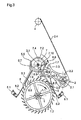
- the escape wheel 1.2 is stationary and rests by one of its teeth on the rest surface 5.4 of the first trigger 5 ( figures 2 and 16 ).
- the pendulum 3 crosses its additional arc descending to the point of elongation of 25 °.
- the impulse pin 7.7 of the plate 7 enters the range 2.3 of the impulse mobile 2 without touching it.
- the release nose 7.6 of the plate 7 comes into contact with the leaf spring 5.6 of the first trigger 5 and pushes this leaf spring 5.6 and all the first trigger whose flexible portion 5.2 flexes to move the resting surface 5.4 away from the tooth of the escape wheel 1.2 with which it is in contact.
- the rest surface 5.4 slides substantially radially on the tooth of the escape wheel 1.2. During this sliding the escape wheel 1.2 does not move yet, the first trigger 5 travels the rest distance, safety necessary to guarantee the locking of the escape wheel despite imperfections of the components due to manufacturing tolerances.
- the escape wheel accelerates driven that it is by the barrel and the gear of the watch movement.
- the rotation of the escape wheel 1.2 drives the impulse wheel 2 by its hook 2.6 which is always in engagement with a tooth of the escape wheel 1.2.
- the fork 2.3 of the impulse mobile 2 catches the impulse pin 7.7 of the plate 7 and transmits a pulse to the balance until the next tooth of the escape wheel 1.2 comes to rest on the rest surface 5.4 of the first trigger which once it has escaped the release nose 7.6 of the plate 7 has returned to rest position under the effect of its own elasticity in contact with the escape wheel.
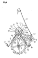
- the escape wheel 1.2 is again blocked ( figure 4 ).
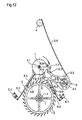
- the figure 13 illustrates the torque C transmitted to the balance 3 by the pulse wheel 2 during the arming phase as a function of the angle ⁇ of the angular displacement of the pulse wheel 2.
- C2 represents the torque at the pulse wheel 2 set to disposal by the escape wheel when the barrel of the watch movement is fully armed.
- C1 represents the torque available at the end of the barrel power reserve. Whatever the winding of the barrel, we therefore always have at least the torque C 1 available to transmit energy to the balance 3.
- the impulse wheel 2 receives from the escape wheel 1.2 by its hook 2.6 a torque at least equal to C1.
- This pair switches the impulse wheel 2 from its position ⁇ 0 (fork 2.3 on the left) to position ⁇ 1 (fork 2.3 on the right).
- a part (E var + E 1 ) of the energy transmitted to the impulse mobile is transmitted by the range 2.3 thereof to the impulse pin 7.7 and therefore to the balance 3 while another part E2 of the available energy is used to arm the impulse spring 2.4 of the impulse mobile.
- the distribution between the energy E1 transmitted to the beam and the E2 used to arm the spring 2.4 of the pulse wheel 2 depends on the characteristic or constant K of this spring 2.4 as can be seen by comparing the Figures 13 and 14 .
- the slope of the characteristic curve of the spring 2.4 modifies the distribution of energy over time between the pulse given to the balance 3 and the armature of the mobile spring 2.4. pulse 2 during the arming phase.
- Figures 13 and 14 show the line "0" linking the center of rotation of the balance 3 to the center of rotation of the impulse mobile 2. This line, perfectly centered between the extreme positions ⁇ 0 and ⁇ 1 of the impulse mobile, also corresponds to the position the theoretical dead point of the oscillator.
- the release pin 7.10 of the plate 7 slides on the release spring 6.8 of the second trigger 6 and forces this second detent against the second stop 9. In doing so the release spring 6.8 is deformed to let the release pin 7.10 then returns to the rest position.
- the impulse pin 7.7 of the plate 7 leaves the fork 2.3 of the impulse mobile 2 and the pendulum carries out its additional ascending arc with a clockwise movement to the point of return of the pendulum 3.
- the second alternation or mute phase will be described below.
- the escape wheel 1.2 remains at rest throughout this phase supported by one of its teeth on the rest surface 5.4 of the first trigger 5. As a result the wheel does not move either.
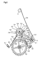
- the balance returns counterclockwise from its additional arc ( figure 5 ).
- the release peg 7.10 of the plate 7 comes into contact with the driving abutment 6.9 of the second detent 6 and displaces this second detent 6 by bending its elastic portion 6.2 in the direction of the pulse wheel 2 driving through its lateral face 6.4 the hook 2.6 of the mobile 2.
- the hook 2.6 of the impulse wheel slides on the tooth of the escape wheel 1.2 and after having traveled the rest distance this hook 2.6 escapes the escape wheel 1.2 and releases the mobile of impulse 2 ( figure 6 ).
- Pulse wheel 2 pivots clockwise under the action of its pulse spring 2.4 which was armed during the arming phase.
- the range 2.3 of the impulse mobile 2 catches the impulse pin 7.7 of the plate 7 and transmits a pulse to the pendulum 3.
- the release pin 7.10 of the plate 7 escapes the driving abutment 6.9 of the second trigger 6 and the latter returns to the rest position against the second stop 9 by its own elasticity ( figure 7 ).
- the energy E2 transmitted to the balance 3 by the pulse wheel 2 during this silent phase is the one that the spring 2.4 of the mobile pulse 2 had stored during the winding phase.
- the release nose 7.6 of the plate 7 passes the first detent 5 by deformation of its leaf spring 5.6 ( figure 8 ).
- the impulse pin 7.7 of the plate 7 leaves the fork 2.3 of the impulse mobile 2 and the rocker performs its additional arc ascending with a counterclockwise movement to the point of return.
- the mechanism is found in the position illustrated in figure 2 and a new cycle can begin.
- this escape mechanism comprises an escape wheel, a pulse mobile and control means.
- the escape wheel transmits, during an alternation of the pendulum, the energy of the barrel impulse mobile that arms his spring and transmits a portion of the energy received pendulum.
- the impulse mobile transmits to said balance of the energy supplied by its pulse spring previously armed during the previous alternation.
- This exhaust mechanism thus achieves a blowout escape in which there is necessarily a power transmission to the balance during each alternation thereof.
- the impulse spring 2.4 of the impulse wheel 2 can be produced in different ways, for example by a spiral spring or as in the example described by a leaf spring, which makes it possible to obtain as flat a possible assembly as possible that a characteristic or high slope of the elasticity curve of this spring.
- the high stiffness of the impulse spring 2 pulse pulse 2 causes a strong pulse before the dead point that it delivers immediately to the pulse. oscillator here the balance-spiral. The energy losses due to the clearance are thus immediately compensated.
- the torque of the impulse spring 2.4 of the mobile pulse 2 armed is only slightly lower than the torque transmitted by the wheel, there is almost a balance of strength.
- the driving force must necessarily be greater than the maximum torque of the impulse spring 2.4 pulse 2 to ensure the complete arming of the pulse spring and the impulse mobile and the proper positioning of the moving parts of the mechanism.
- the maximum torque on the pulse wheel 2 does not exceed 95% of the minimum torque, at the end of the power reserve, provided by the escape wheel 1.2.
- the exhaust uses a portion of the energy available to arm the spring 2.4 which gradually decreases the kinetic energy of the escape wheel by the increasing resistance of the spring 2.4 instead of damping said kinetic energy entirely by the shock of the exhaust wheel entering full speed in abutment with the pallet of the steering element (anchor or trigger) and causing the ticking of the movement.
- the escape wheel 1.2 does not recoil.
- the control elements that are the two detents 5 and 6 are prestressed and find their rest position after shock thanks to their own elasticity.
- This exhaust mechanism makes it possible to significantly increase the number of teeth of the escape wheel without increasing its diameter. It is possible to double or more the number of teeth of the escape wheel compared to a classic anchor escapement without increasing the diameter. It is then possible to use this escapement mechanism with a high frequency oscillator, 5 Hertz or more, without the need to provide an additional mobile between the second wheel and the exhaust pinion and without the need for additional reports. gearing to maintain the angular velocity imposed by the second wheel. In fact, a large reduction is already achieved by the fact that the escape wheel advances only one step for two alternations of the oscillator and the fact of being able to increase the number of teeth in a given diameter of the wheel. exhaust through the use of the impulse mobile 2.
- the escape mechanism is self-starting because the oscillator receives energy during each of its alternations.
- the present escapement mechanism makes it possible to influence the chronometric behavior of the escapement at will and to eliminate the run-out errors due to the escapement or to balance other isochronism defects, for example originating from the spiral, by an adjustment of the exhaust mechanism. Indeed in this escape mechanism it is possible to adjust and adjust the temporal distribution of energy supplied to the balance in the arming phase and in the dummy phase relative to the neutral point of the oscillator by playing on the stiffness or elastic characteristic of the impulse spring 2.4 of the impulse mobile. It is thus possible by choosing the characteristic of this impulse spring 2.4 of the impulse mobile to obtain an escapement exhibiting neither advance nor chronometric delay.
- the cogwheel of the clockwork movement equipped with it advances only once per period, ie during alternating half of the oscillator. During the silent alternation the gear does not turn, although the oscillator receives a pulse. This reduces the energy loss due to the inertia of the gear when it is started.
- the impulse wheel and the escape wheel are almost in force balance. This feature allows to recover the kinetic energy stored in the wheel.
- the impulse spring 2.4 of the mobile of pulse 2 is almost discharged before the hook 2.6 of said mobile pulse 2 does not fall on a tooth of the escape wheel, there will also be less energy dissipated.
- the present exhaust mechanism is particularly well adapted to be integrated in the cages of a vortex at high oscillator frequency, because it allows despite the use of a high frequency oscillator the conservation of a gear ratio Ordinary because of the large number of teeth of the escape wheel and moreover, it allows to recover the kinetic energy of the wheel including vortex cages.
- the escapement mechanism is intended to equip watch movements which comprise a frame on which a barrel is mounted, a gear train kinematically connecting this barrel with an escape wheel and an oscillator provided with of a pendulum.
- This escapement mechanism comprises an escape wheel forming part of the escape wheel and a plate secured to the axis of the balance comprising a pulse pin.
- control means comprise control members carried by the plate 7 formed in the example illustrated by the release nose 7.6 and the release pin 7.10.
- control means further comprise either an anchor or, as in the example shown, two detents controlled by said control members.
- the escape mechanism according to the invention also comprises security devices carried by the plate 7, in the example illustrated the skirt 7.4 of the large plate and the periphery of the small plate 7.2, preventing any inadvertent movement, for example under the effect of shocks, control means of the mechanism.
- the pulse spring of the impulse mobile can be realized in different ways, a blade spring as in the example described but also a spiral spring or a coil spring.
- the arm, terminated by a hook, of the impulse can be an elastic arm as in the example described or realized by a connecting rod articulated on the body of the impulse mobile and constrained against the escape wheel by a spring or still be realized by a linear guide.
- the impulse spring 2.4 of the impulse mobile could be removably attached to the body 2.2 of the impulse mobile to be able to adapt to this impulse mobile a pulse spring corresponding to the energy that we want transmit to the pendulum during the second alternations of it as has been explained in relation to the Figures 13 and 14 .
- control means and safety devices may be different from that described in the illustrated example provided that the functions necessary for the operation of the exhaust mechanism according to the invention are realized.
- the frequency of the oscillator can be different from 5 Hertz, for example 3 or 4 Hertz. In other variants the frequency can be higher than 5 Hertz.
- this escapement mechanism for a timepiece is intended to transmit to a mechanical oscillator pulses once alternately to maintain its movement.
- An escape wheel provides as it advances by one step during a first alternation of the oscillator the total energy necessary to maintain the movement of the oscillator during two successive alternations of the oscillator and that this oscillator receives during a first alternation only a part of the energy and that the other part of this total energy is stored by a mobile pulse to be transmitted to the oscillator during a second alternation of it.
- control means cause the loss of contact between the escape wheel and the impulse wheel during the second alternation of the oscillator during which the impulse wheel returns to a first position ( ⁇ 1) under the effect of the energy stored during the first alternation of the oscillator while transmitting a portion of this energy to said oscillator during its second alternation.
- this impulse mobile is connected to the frame of the movement of the timepiece by a prestressed elastic element, in the example illustrated the pulse spring 2.4.
- the invention also relates to monobloc detents for themselves as described and illustrated in FIGS. Figures 16 and 17 but may of course be used in other types of exhaust than that described in the foregoing.
- the existing detents for escapes of watch movements are complex and formed of several pieces assembled.
- the one-piece detents described with reference to this escapement are simple, easy to machine with modern machining methods (DRIE) and can of course be used on all types of escapements.
- DRIE modern machining methods
- One of their originalities is to be made in one piece.
- Another of their originalities is that they each have two portions 5.2, 5.6 or 6.2, 6.8 elastics.
- these detents can be manufactured in brittle materials, not plastically deformable, such as silicon for example.
- the flexible blade forming the release spring 6.8 being tangential to the trajectory of the release pin 7.10, there is no catch-up effect as for the first relaxation 5.
- the release is immediate.
- This second relaxation 6 can also be performed by the DRIE method and be monobloc.
- this second trigger can also be secured by a skirt that would replace the cam 7.2 or small plateau tray 7 described above.
Landscapes
- Physics & Mathematics (AREA)
- General Physics & Mathematics (AREA)
- Measurement Of Unknown Time Intervals (AREA)
- Micromachines (AREA)
- Vibration Prevention Devices (AREA)
Applications Claiming Priority (1)
| Application Number | Priority Date | Filing Date | Title |
|---|---|---|---|
| CH00601/12A CH706462B1 (fr) | 2012-05-01 | 2012-05-01 | Mouvement pour pièce d'horlogerie comprenant un mécanisme d'échappement libre. |
Publications (3)
| Publication Number | Publication Date |
|---|---|
| EP2660661A2 true EP2660661A2 (de) | 2013-11-06 |
| EP2660661A3 EP2660661A3 (de) | 2018-04-11 |
| EP2660661B1 EP2660661B1 (de) | 2019-06-26 |
Family
ID=48430399
Family Applications (1)
| Application Number | Title | Priority Date | Filing Date |
|---|---|---|---|
| EP13002120.7A Active EP2660661B1 (de) | 2012-05-01 | 2013-04-23 | Freier Hemmungsmechanismus für Uhrwerk, Uhrwerk und/oder Uhr, das/die diesen Hemmungsmechanismus umfasst |
Country Status (2)
| Country | Link |
|---|---|
| EP (1) | EP2660661B1 (de) |
| CH (1) | CH706462B1 (de) |
Cited By (4)
| Publication number | Priority date | Publication date | Assignee | Title |
|---|---|---|---|---|
| CN111474843A (zh) * | 2019-01-24 | 2020-07-31 | 瑞士电子与微技术中心股份公司-研究与发展 | 机械钟表调节器 |
| JP2024516910A (ja) * | 2021-05-12 | 2024-04-17 | ロレックス・ソシエテ・アノニム | 時計のための定エネルギー脱進機 |
| US11988993B2 (en) | 2018-07-02 | 2024-05-21 | Complitime Sa | Timepiece escapement mechanism |
| US12055896B2 (en) | 2016-12-23 | 2024-08-06 | Manufacture D'horlogerie Audemars Piguet Sa | Flexible monolithic component for a timepiece |
Family Cites Families (4)
| Publication number | Priority date | Publication date | Assignee | Title |
|---|---|---|---|---|
| US197430A (en) * | 1877-11-20 | Improvement in watch-escapements | ||
| ATE363673T1 (de) * | 2003-12-04 | 2007-06-15 | Montres Breguet Sa | Chronometerhemmung für armbanduhren |
| EP1770452A1 (de) * | 2005-09-30 | 2007-04-04 | Peter Baumberger | Chronometerhemmung für Uhren |
| CH703814B1 (fr) * | 2010-09-16 | 2015-05-29 | Blancpain Sa | Echappement à ancre pour mouvement d'horlogerie. |
-
2012
- 2012-05-01 CH CH00601/12A patent/CH706462B1/fr unknown
-
2013
- 2013-04-23 EP EP13002120.7A patent/EP2660661B1/de active Active
Non-Patent Citations (1)
| Title |
|---|
| None |
Cited By (5)
| Publication number | Priority date | Publication date | Assignee | Title |
|---|---|---|---|---|
| US12055896B2 (en) | 2016-12-23 | 2024-08-06 | Manufacture D'horlogerie Audemars Piguet Sa | Flexible monolithic component for a timepiece |
| US11988993B2 (en) | 2018-07-02 | 2024-05-21 | Complitime Sa | Timepiece escapement mechanism |
| CN111474843A (zh) * | 2019-01-24 | 2020-07-31 | 瑞士电子与微技术中心股份公司-研究与发展 | 机械钟表调节器 |
| CN111474843B (zh) * | 2019-01-24 | 2022-12-02 | 瑞士电子与微技术中心股份公司-研究与发展 | 机械钟表调节器 |
| JP2024516910A (ja) * | 2021-05-12 | 2024-04-17 | ロレックス・ソシエテ・アノニム | 時計のための定エネルギー脱進機 |
Also Published As
| Publication number | Publication date |
|---|---|
| CH706462A2 (fr) | 2013-11-15 |
| CH706462B1 (fr) | 2017-04-28 |
| EP2660661B1 (de) | 2019-06-26 |
| EP2660661A3 (de) | 2018-04-11 |
Similar Documents
| Publication | Publication Date | Title |
|---|---|---|
| EP2831677B1 (de) | Flexibler uhrhemmungsmechanismus | |
| EP2224292B1 (de) | Chronometerhemmung für Uhrwerk | |
| US8439556B2 (en) | Synchronous escapement for a timepiece mechanism | |
| US7192180B2 (en) | Detent escapement for timepiece | |
| EP2645189A1 (de) | Flexibler Uhrhemmungsmechanismus | |
| EP2660661B1 (de) | Freier Hemmungsmechanismus für Uhrwerk, Uhrwerk und/oder Uhr, das/die diesen Hemmungsmechanismus umfasst | |
| EP2607968B1 (de) | Uhrhemmungsmechanismus | |
| CH704764A2 (fr) | Mécanisme d'échappement notamment pour mouvement d'horlogerie. | |
| EP3153935B1 (de) | Chronometerhemmungsmechanismus eines uhrwerks mit konstanter kraft | |
| EP3686693B1 (de) | Mechanische uhr-regulierungsvorrichtung | |
| CH710925B1 (fr) | Mécanisme d'échappement. | |
| CH713530B1 (fr) | Echappement, mouvement de pièce d'horlogerie et pièce d'horlogerie. | |
| EP3825780A1 (de) | Mechanische uhreinstellvorrichtung, die einen uhrhemmungsmechanismus mit konstanter kraft umfasst | |
| EP3818417B1 (de) | Uhrhemmungsmechanismus | |
| EP3510449B1 (de) | Hemmungsmechanismus | |
| CH712084B1 (fr) | Détente pour un mécanisme d'échappement libre d'un mouvement d'horlogerie. | |
| EP3019916A2 (de) | Hemmung für eine uhr mit einem tourbillon ohne käfig | |
| EP3623875A1 (de) | Uhrhemmungsmechanismus mit bistabiler blattfeder | |
| EP3781993B1 (de) | Frei direkthemmung mechanismus für uhren. | |
| EP4160323A1 (de) | Mechanische einstellvorrichtung für uhr mit selbstanlaufendem, halb freistehendem hemmungsmechanismus mit geringem anstellwinkel | |
| WO2018002773A1 (fr) | Echappement d'horlogerie | |
| EP3475763B1 (de) | Uhrwerkshemmung | |
| CH709755B1 (fr) | Mécanisme d'horlogerie muni d'un résonateur diapason. | |
| CH712807B1 (fr) | Mécanisme d'échappement. |
Legal Events
| Date | Code | Title | Description |
|---|---|---|---|
| PUAI | Public reference made under article 153(3) epc to a published international application that has entered the european phase |
Free format text: ORIGINAL CODE: 0009012 |
|
| AK | Designated contracting states |
Kind code of ref document: A2 Designated state(s): AL AT BE BG CH CY CZ DE DK EE ES FI FR GB GR HR HU IE IS IT LI LT LU LV MC MK MT NL NO PL PT RO RS SE SI SK SM TR |
|
| AX | Request for extension of the european patent |
Extension state: BA ME |
|
| RIN1 | Information on inventor provided before grant (corrected) |
Inventor name: MUENCH, JAN |
|
| RIC1 | Information provided on ipc code assigned before grant |
Ipc: G04B 15/06 20060101AFI20171012BHEP Ipc: G04B 15/14 20060101ALI20171012BHEP |
|
| PUAL | Search report despatched |
Free format text: ORIGINAL CODE: 0009013 |
|
| AK | Designated contracting states |
Kind code of ref document: A3 Designated state(s): AL AT BE BG CH CY CZ DE DK EE ES FI FR GB GR HR HU IE IS IT LI LT LU LV MC MK MT NL NO PL PT RO RS SE SI SK SM TR |
|
| AX | Request for extension of the european patent |
Extension state: BA ME |
|
| RIC1 | Information provided on ipc code assigned before grant |
Ipc: G04B 15/14 20060101ALI20180306BHEP Ipc: G04B 15/06 20060101AFI20180306BHEP |
|
| STAA | Information on the status of an ep patent application or granted ep patent |
Free format text: STATUS: REQUEST FOR EXAMINATION WAS MADE |
|
| 17P | Request for examination filed |
Effective date: 20180913 |
|
| RBV | Designated contracting states (corrected) |
Designated state(s): AL AT BE BG CH CY CZ DE DK EE ES FI FR GB GR HR HU IE IS IT LI LT LU LV MC MK MT NL NO PL PT RO RS SE SI SK SM TR |
|
| GRAP | Despatch of communication of intention to grant a patent |
Free format text: ORIGINAL CODE: EPIDOSNIGR1 |
|
| STAA | Information on the status of an ep patent application or granted ep patent |
Free format text: STATUS: GRANT OF PATENT IS INTENDED |
|
| INTG | Intention to grant announced |
Effective date: 20190227 |
|
| GRAS | Grant fee paid |
Free format text: ORIGINAL CODE: EPIDOSNIGR3 |
|
| GRAA | (expected) grant |
Free format text: ORIGINAL CODE: 0009210 |
|
| STAA | Information on the status of an ep patent application or granted ep patent |
Free format text: STATUS: THE PATENT HAS BEEN GRANTED |
|
| AK | Designated contracting states |
Kind code of ref document: B1 Designated state(s): AL AT BE BG CH CY CZ DE DK EE ES FI FR GB GR HR HU IE IS IT LI LT LU LV MC MK MT NL NO PL PT RO RS SE SI SK SM TR |
|
| REG | Reference to a national code |
Ref country code: GB Ref legal event code: FG4D Free format text: NOT ENGLISH |
|
| REG | Reference to a national code |
Ref country code: CH Ref legal event code: EP |
|
| REG | Reference to a national code |
Ref country code: AT Ref legal event code: REF Ref document number: 1149006 Country of ref document: AT Kind code of ref document: T Effective date: 20190715 |
|
| REG | Reference to a national code |
Ref country code: DE Ref legal event code: R096 Ref document number: 602013056995 Country of ref document: DE |
|
| REG | Reference to a national code |
Ref country code: IE Ref legal event code: FG4D Free format text: LANGUAGE OF EP DOCUMENT: FRENCH |
|
| REG | Reference to a national code |
Ref country code: CH Ref legal event code: NV Representative=s name: MICHELI AND CIE SA, CH |
|
| REG | Reference to a national code |
Ref country code: NL Ref legal event code: MP Effective date: 20190626 |
|
| PG25 | Lapsed in a contracting state [announced via postgrant information from national office to epo] |
Ref country code: SE Free format text: LAPSE BECAUSE OF FAILURE TO SUBMIT A TRANSLATION OF THE DESCRIPTION OR TO PAY THE FEE WITHIN THE PRESCRIBED TIME-LIMIT Effective date: 20190626 Ref country code: AL Free format text: LAPSE BECAUSE OF FAILURE TO SUBMIT A TRANSLATION OF THE DESCRIPTION OR TO PAY THE FEE WITHIN THE PRESCRIBED TIME-LIMIT Effective date: 20190626 Ref country code: LT Free format text: LAPSE BECAUSE OF FAILURE TO SUBMIT A TRANSLATION OF THE DESCRIPTION OR TO PAY THE FEE WITHIN THE PRESCRIBED TIME-LIMIT Effective date: 20190626 Ref country code: HR Free format text: LAPSE BECAUSE OF FAILURE TO SUBMIT A TRANSLATION OF THE DESCRIPTION OR TO PAY THE FEE WITHIN THE PRESCRIBED TIME-LIMIT Effective date: 20190626 Ref country code: NO Free format text: LAPSE BECAUSE OF FAILURE TO SUBMIT A TRANSLATION OF THE DESCRIPTION OR TO PAY THE FEE WITHIN THE PRESCRIBED TIME-LIMIT Effective date: 20190926 Ref country code: FI Free format text: LAPSE BECAUSE OF FAILURE TO SUBMIT A TRANSLATION OF THE DESCRIPTION OR TO PAY THE FEE WITHIN THE PRESCRIBED TIME-LIMIT Effective date: 20190626 |
|
| REG | Reference to a national code |
Ref country code: LT Ref legal event code: MG4D |
|
| PG25 | Lapsed in a contracting state [announced via postgrant information from national office to epo] |
Ref country code: GR Free format text: LAPSE BECAUSE OF FAILURE TO SUBMIT A TRANSLATION OF THE DESCRIPTION OR TO PAY THE FEE WITHIN THE PRESCRIBED TIME-LIMIT Effective date: 20190927 Ref country code: LV Free format text: LAPSE BECAUSE OF FAILURE TO SUBMIT A TRANSLATION OF THE DESCRIPTION OR TO PAY THE FEE WITHIN THE PRESCRIBED TIME-LIMIT Effective date: 20190626 Ref country code: BG Free format text: LAPSE BECAUSE OF FAILURE TO SUBMIT A TRANSLATION OF THE DESCRIPTION OR TO PAY THE FEE WITHIN THE PRESCRIBED TIME-LIMIT Effective date: 20190926 Ref country code: RS Free format text: LAPSE BECAUSE OF FAILURE TO SUBMIT A TRANSLATION OF THE DESCRIPTION OR TO PAY THE FEE WITHIN THE PRESCRIBED TIME-LIMIT Effective date: 20190626 |
|
| REG | Reference to a national code |
Ref country code: AT Ref legal event code: MK05 Ref document number: 1149006 Country of ref document: AT Kind code of ref document: T Effective date: 20190626 |
|
| PG25 | Lapsed in a contracting state [announced via postgrant information from national office to epo] |
Ref country code: AT Free format text: LAPSE BECAUSE OF FAILURE TO SUBMIT A TRANSLATION OF THE DESCRIPTION OR TO PAY THE FEE WITHIN THE PRESCRIBED TIME-LIMIT Effective date: 20190626 Ref country code: EE Free format text: LAPSE BECAUSE OF FAILURE TO SUBMIT A TRANSLATION OF THE DESCRIPTION OR TO PAY THE FEE WITHIN THE PRESCRIBED TIME-LIMIT Effective date: 20190626 Ref country code: PT Free format text: LAPSE BECAUSE OF FAILURE TO SUBMIT A TRANSLATION OF THE DESCRIPTION OR TO PAY THE FEE WITHIN THE PRESCRIBED TIME-LIMIT Effective date: 20191028 Ref country code: SK Free format text: LAPSE BECAUSE OF FAILURE TO SUBMIT A TRANSLATION OF THE DESCRIPTION OR TO PAY THE FEE WITHIN THE PRESCRIBED TIME-LIMIT Effective date: 20190626 Ref country code: RO Free format text: LAPSE BECAUSE OF FAILURE TO SUBMIT A TRANSLATION OF THE DESCRIPTION OR TO PAY THE FEE WITHIN THE PRESCRIBED TIME-LIMIT Effective date: 20190626 Ref country code: CZ Free format text: LAPSE BECAUSE OF FAILURE TO SUBMIT A TRANSLATION OF THE DESCRIPTION OR TO PAY THE FEE WITHIN THE PRESCRIBED TIME-LIMIT Effective date: 20190626 Ref country code: NL Free format text: LAPSE BECAUSE OF FAILURE TO SUBMIT A TRANSLATION OF THE DESCRIPTION OR TO PAY THE FEE WITHIN THE PRESCRIBED TIME-LIMIT Effective date: 20190626 |
|
| PG25 | Lapsed in a contracting state [announced via postgrant information from national office to epo] |
Ref country code: ES Free format text: LAPSE BECAUSE OF FAILURE TO SUBMIT A TRANSLATION OF THE DESCRIPTION OR TO PAY THE FEE WITHIN THE PRESCRIBED TIME-LIMIT Effective date: 20190626 Ref country code: IT Free format text: LAPSE BECAUSE OF FAILURE TO SUBMIT A TRANSLATION OF THE DESCRIPTION OR TO PAY THE FEE WITHIN THE PRESCRIBED TIME-LIMIT Effective date: 20190626 Ref country code: SM Free format text: LAPSE BECAUSE OF FAILURE TO SUBMIT A TRANSLATION OF THE DESCRIPTION OR TO PAY THE FEE WITHIN THE PRESCRIBED TIME-LIMIT Effective date: 20190626 Ref country code: IS Free format text: LAPSE BECAUSE OF FAILURE TO SUBMIT A TRANSLATION OF THE DESCRIPTION OR TO PAY THE FEE WITHIN THE PRESCRIBED TIME-LIMIT Effective date: 20191026 |
|
| PG25 | Lapsed in a contracting state [announced via postgrant information from national office to epo] |
Ref country code: TR Free format text: LAPSE BECAUSE OF FAILURE TO SUBMIT A TRANSLATION OF THE DESCRIPTION OR TO PAY THE FEE WITHIN THE PRESCRIBED TIME-LIMIT Effective date: 20190626 |
|
| PG25 | Lapsed in a contracting state [announced via postgrant information from national office to epo] |
Ref country code: PL Free format text: LAPSE BECAUSE OF FAILURE TO SUBMIT A TRANSLATION OF THE DESCRIPTION OR TO PAY THE FEE WITHIN THE PRESCRIBED TIME-LIMIT Effective date: 20190626 Ref country code: DK Free format text: LAPSE BECAUSE OF FAILURE TO SUBMIT A TRANSLATION OF THE DESCRIPTION OR TO PAY THE FEE WITHIN THE PRESCRIBED TIME-LIMIT Effective date: 20190626 |
|
| PG25 | Lapsed in a contracting state [announced via postgrant information from national office to epo] |
Ref country code: IS Free format text: LAPSE BECAUSE OF FAILURE TO SUBMIT A TRANSLATION OF THE DESCRIPTION OR TO PAY THE FEE WITHIN THE PRESCRIBED TIME-LIMIT Effective date: 20200224 |
|
| REG | Reference to a national code |
Ref country code: DE Ref legal event code: R097 Ref document number: 602013056995 Country of ref document: DE |
|
| PLBE | No opposition filed within time limit |
Free format text: ORIGINAL CODE: 0009261 |
|
| STAA | Information on the status of an ep patent application or granted ep patent |
Free format text: STATUS: NO OPPOSITION FILED WITHIN TIME LIMIT |
|
| PG2D | Information on lapse in contracting state deleted |
Ref country code: IS |
|
| 26N | No opposition filed |
Effective date: 20200603 |
|
| PG25 | Lapsed in a contracting state [announced via postgrant information from national office to epo] |
Ref country code: SI Free format text: LAPSE BECAUSE OF FAILURE TO SUBMIT A TRANSLATION OF THE DESCRIPTION OR TO PAY THE FEE WITHIN THE PRESCRIBED TIME-LIMIT Effective date: 20190626 |
|
| REG | Reference to a national code |
Ref country code: DE Ref legal event code: R119 Ref document number: 602013056995 Country of ref document: DE |
|
| PG25 | Lapsed in a contracting state [announced via postgrant information from national office to epo] |
Ref country code: MC Free format text: LAPSE BECAUSE OF FAILURE TO SUBMIT A TRANSLATION OF THE DESCRIPTION OR TO PAY THE FEE WITHIN THE PRESCRIBED TIME-LIMIT Effective date: 20190626 |
|
| PG25 | Lapsed in a contracting state [announced via postgrant information from national office to epo] |
Ref country code: DE Free format text: LAPSE BECAUSE OF NON-PAYMENT OF DUE FEES Effective date: 20201103 Ref country code: LU Free format text: LAPSE BECAUSE OF NON-PAYMENT OF DUE FEES Effective date: 20200423 Ref country code: FR Free format text: LAPSE BECAUSE OF NON-PAYMENT OF DUE FEES Effective date: 20200430 |
|
| REG | Reference to a national code |
Ref country code: BE Ref legal event code: MM Effective date: 20200430 |
|
| PG25 | Lapsed in a contracting state [announced via postgrant information from national office to epo] |
Ref country code: BE Free format text: LAPSE BECAUSE OF NON-PAYMENT OF DUE FEES Effective date: 20200430 |
|
| GBPC | Gb: european patent ceased through non-payment of renewal fee |
Effective date: 20200423 |
|
| PG25 | Lapsed in a contracting state [announced via postgrant information from national office to epo] |
Ref country code: IE Free format text: LAPSE BECAUSE OF NON-PAYMENT OF DUE FEES Effective date: 20200423 Ref country code: GB Free format text: LAPSE BECAUSE OF NON-PAYMENT OF DUE FEES Effective date: 20200423 |
|
| PG25 | Lapsed in a contracting state [announced via postgrant information from national office to epo] |
Ref country code: MT Free format text: LAPSE BECAUSE OF FAILURE TO SUBMIT A TRANSLATION OF THE DESCRIPTION OR TO PAY THE FEE WITHIN THE PRESCRIBED TIME-LIMIT Effective date: 20190626 Ref country code: CY Free format text: LAPSE BECAUSE OF FAILURE TO SUBMIT A TRANSLATION OF THE DESCRIPTION OR TO PAY THE FEE WITHIN THE PRESCRIBED TIME-LIMIT Effective date: 20190626 |
|
| PG25 | Lapsed in a contracting state [announced via postgrant information from national office to epo] |
Ref country code: MK Free format text: LAPSE BECAUSE OF FAILURE TO SUBMIT A TRANSLATION OF THE DESCRIPTION OR TO PAY THE FEE WITHIN THE PRESCRIBED TIME-LIMIT Effective date: 20190626 |
|
| P01 | Opt-out of the competence of the unified patent court (upc) registered |
Effective date: 20230521 |
|
| PGFP | Annual fee paid to national office [announced via postgrant information from national office to epo] |
Ref country code: CH Payment date: 20250501 Year of fee payment: 13 |
|
| REG | Reference to a national code |
Ref country code: CH Ref legal event code: U11 Free format text: ST27 STATUS EVENT CODE: U-0-0-U10-U11 (AS PROVIDED BY THE NATIONAL OFFICE) Effective date: 20260501 |