EP2660808A2 - Übertragung von Alternativinhalt über Standardeinrichtungsverbinder - Google Patents
Übertragung von Alternativinhalt über Standardeinrichtungsverbinder Download PDFInfo
- Publication number
- EP2660808A2 EP2660808A2 EP13179073.5A EP13179073A EP2660808A2 EP 2660808 A2 EP2660808 A2 EP 2660808A2 EP 13179073 A EP13179073 A EP 13179073A EP 2660808 A2 EP2660808 A2 EP 2660808A2
- Authority
- EP
- European Patent Office
- Prior art keywords
- mode
- pin
- signal
- data
- standard
- Prior art date
- Legal status (The legal status is an assumption and is not a legal conclusion. Google has not performed a legal analysis and makes no representation as to the accuracy of the status listed.)
- Withdrawn
Links
Images






Classifications
-
- H—ELECTRICITY
- H04—ELECTRIC COMMUNICATION TECHNIQUE
- H04L—TRANSMISSION OF DIGITAL INFORMATION, e.g. TELEGRAPHIC COMMUNICATION
- H04L9/00—Cryptographic mechanisms or cryptographic arrangements for secret or secure communications; Network security protocols
- H04L9/40—Network security protocols
-
- G—PHYSICS
- G09—EDUCATION; CRYPTOGRAPHY; DISPLAY; ADVERTISING; SEALS
- G09G—ARRANGEMENTS OR CIRCUITS FOR CONTROL OF INDICATING DEVICES USING STATIC MEANS TO PRESENT VARIABLE INFORMATION
- G09G5/00—Control arrangements or circuits for visual indicators common to cathode-ray tube indicators and other visual indicators
- G09G5/003—Details of a display terminal, the details relating to the control arrangement of the display terminal and to the interfaces thereto
- G09G5/006—Details of the interface to the display terminal
-
- G—PHYSICS
- G06—COMPUTING OR CALCULATING; COUNTING
- G06F—ELECTRIC DIGITAL DATA PROCESSING
- G06F13/00—Interconnection of, or transfer of information or other signals between, memories, input/output devices or central processing units
- G06F13/14—Handling requests for interconnection or transfer
-
- G—PHYSICS
- G06—COMPUTING OR CALCULATING; COUNTING
- G06F—ELECTRIC DIGITAL DATA PROCESSING
- G06F13/00—Interconnection of, or transfer of information or other signals between, memories, input/output devices or central processing units
- G06F13/38—Information transfer, e.g. on bus
- G06F13/40—Bus structure
- G06F13/4063—Device-to-bus coupling
- G06F13/409—Mechanical coupling
-
- H—ELECTRICITY
- H04—ELECTRIC COMMUNICATION TECHNIQUE
- H04L—TRANSMISSION OF DIGITAL INFORMATION, e.g. TELEGRAPHIC COMMUNICATION
- H04L12/00—Data switching networks
- H04L12/28—Data switching networks characterised by path configuration, e.g. LAN [Local Area Networks] or WAN [Wide Area Networks]
- H04L12/40—Bus networks
- H04L12/40006—Architecture of a communication node
-
- G—PHYSICS
- G09—EDUCATION; CRYPTOGRAPHY; DISPLAY; ADVERTISING; SEALS
- G09G—ARRANGEMENTS OR CIRCUITS FOR CONTROL OF INDICATING DEVICES USING STATIC MEANS TO PRESENT VARIABLE INFORMATION
- G09G2370/00—Aspects of data communication
- G09G2370/10—Use of a protocol of communication by packets in interfaces along the display data pipeline
-
- G—PHYSICS
- G09—EDUCATION; CRYPTOGRAPHY; DISPLAY; ADVERTISING; SEALS
- G09G—ARRANGEMENTS OR CIRCUITS FOR CONTROL OF INDICATING DEVICES USING STATIC MEANS TO PRESENT VARIABLE INFORMATION
- G09G2370/00—Aspects of data communication
- G09G2370/12—Use of DVI or HDMI protocol in interfaces along the display data pipeline
Definitions
- Embodiments of the invention generally relate to the field of electronic devices and, more particularly, to a method and apparatus for transmission of alternative content over standard device connectors.
- HDMI TM High-Definition Multimedia Interface
- HDMI provides an interface that allows for the transfer of uncompressed digital high-definition video and audio, together with associated control signals.
- HDMI includes the High-Definition Multimedia Interface 1.3 (Hitachi, Ltd., Matsushita Electric Industrial Co., Ltd., Philips Consumer Electronics, International B.V., Silicon Image, Inc., Sony Corporation, Thomson Inc., and Toshiba Corporation) (June 22, 2006), as well as earlier and later versions of HDMI.
- HDMI is backward and forward compatible with DVI (Digital Video Interface), which contains only video data.
- HDMI is essentially a superset of DVI, containing the same video content with the addition of multi-channel audio and status data content in the gaps, or blanking periods, between bursts of video data.
- MHL TM Mobile High-Definition Link TM
- a handheld MHL device may, for example, allow for direct connection with a presentation or rendering device, including, for example, a television set, video monitor, or projector. Protocols for communication elements may include MHL technology.
- Devices used in conjunction with content storage, transmission, and presentation may include any devices capable of providing, storing, or presenting multimedia data, including television sets, video monitors, projectors, cable and satellite set-top boxes, video players, including DVD (Digital Versatile Disk) and Blu-Ray players, audio players, digital video recorders, smartphones, MIDs (Mobile Internet Devices), PIDs (Personal Internet Devices), computers including notebook computers and netbooks, and other similar devices.
- HDMI and MHL devices utilize TMDS TM (Transition Minimized Differential Signaling) technology.
- TMDS encoding converts 8 bits per TMDS data channel into a 10-bit DC-balanced, transition minimized sequence, which is then transmitted serially across the pair at a rate of 10 bits per TMDS clock period.
- An HDMI connection may include a DDC (Display Data Channel) for configuration and status exchange between a source device and a sink device, and an optional CEC (Consumer Electronics Control) protocol to provide high-level control functions among audiovisual products in a user's environment, and an MHL connection may include a control bus carrying multiplexed control signals.
- DDC Display Data Channel
- CEC Consumer Electronics Control
- Electronic devices may include various different interfaces for the transfer of data, but smaller devices may be limited with regard to connections because of physical size.
- certain handheld and other smaller devices may utilize a micro-USBTM (Universal Serial Bus), mini-USB, or standard USB connector (or socket) compatible with USB protocol, or similar connectors having limited space.
- USB connector or socket
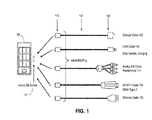
- Figure 1 is an illustration of an embodiment of possible connections to a standard connector
- Figure 2 is an illustration of an embodiment of a connection for a receiving device having a standard connector
- Figure 3 illustrates an embodiment of mapping of high definition data for a micro-USB connector
- Figure 4 illustrates an embodiment of data mapping between HDMI, MHL, and micro-USB/MHL
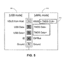
- Figure 5 is an illustration of an embodiment of mapping of signals utilizing a clock signal
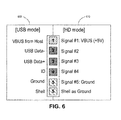
- Figure 6 is an illustration of an embodiment of a high definition mode and a USB mode for a connector including a separate shell;
- Figure 7 is an illustration of an embodiment of a transfer of signals between a USB connection and an HDMI connection
- Figure 8 is an illustration of an embodiment of a device having a switch to select a mode among multiple connection modes
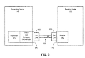
- Figure 9 is an illustration of an embodiment of a connection for a transmitting device transmitting data to a receiving device
- Figure 10 is an illustration of an embodiment of a connection for a receiving device receiving data from a transmitting device.
- Figure 11 is a flow chart illustrating an embodiment of a system for transmission of signals.
- Embodiments of the invention are generally directed to a transmission of alternative content over standard device connectors.
- a method in a first aspect of the invention, includes connecting a first device to a second device utilizing a standard connector, the connector including multiple pins, and detecting whether the second device is operating in a standard mode or an alternative mode. If the second device is operating in the alternative mode, then switching one or more pins of the standard connector for the alternative mode and transmitting or receiving signals for the alternative mode via the plurality of pins of the standard connector.
- an apparatus in a second aspect of the invention, include an interface for a standard connector, wherein the apparatus is to utilize the interface for multiple lines, and wherein the apparatus is to detect a transmission mode of operation for a second apparatus connected to the apparatus via the interface.
- the apparatus further includes a switch to switch the interface between transmission modes, the modes including a first mode and a second mode, the switch to switch one or more connections for the lines to support the first mode and the second mode, and the apparatus to automatically switch to the second mode if the second mode is detected for the second apparatus.
- Embodiments of the invention are generally directed to transmission of alternative content over standard device connectors.
- Mobile device means any mobile electronic device.
- the term “mobile device” includes, but is not limited to, a cellular telephone, smartphone, PDA (personal digital device), MP3 or other format music player, digital camera, video recorder, digital storage device, and other similar devices.
- an apparatus, system, or method provides for transmission of alternative content over existing connectors, such as, for example, transmission of high-definition video and audio content over existing connections.
- a system or method provides for multiple modes to provide for connection for both conventional data and alternative serial data.
- a system provides for re-purposing of existing connections or pins to allow for transmission of alternative content.
- connection elements may be referred to as connectors or as sockets into which connectors may be fitted, but it is intended that the terms may be interchangeable and that either term describes a general connection element for an apparatus.
- alternative data transferred between devices may be multimedia data and associated commands, including HDMI data and commands.
- a mobile device containing high-definition video and audio data and related commands may be connected to a standard HDMI device (such as, for example, a television set, video monitor, projector, or other data presentation device).
- a standard HDMI device such as, for example, a television set, video monitor, projector, or other data presentation device.
- embodiments of the invention are not limited to any particular type of data or device.
- a device is a mobile device utilizing an MHL data connection. While embodiments of the invention are not limited to any particular technology, MHL may utilize a 5 or 6 pin interface that carries audio, video, and auxiliary data between a source and a sink.
- the MHL data may be transmitted via a standard or conventional connector by remapping the data signals to the standard connector.
- power and/or battery charging current may be provided to a mobile device (via a VBUS line) from a presentation or rendering device that is linked to the mobile device via an MHL cable.
- a standard connector may be a micro-USB (Universal Serial Bus) connector, but embodiments are not limited to any particular connector, and may also include, for example, a standard USB or mini-USB connection compatible with USB protocol or a headphone connector.
- USB Universal Serial Bus
- serialized HD high-definition
- a method may be applied to a mini-USB or standard USB connector, a headphone connector, or to another type of connection.
- serialized HD content may be digital audio and/or digital video, such as HDMI (providing video and audio data) or DVI (containing only video), Ethernet, SATA (Serial Advanced Technology Attachment), PCI (Peripheral Component Interface)-express, or high speed lane of USB 3.0.
- a micro-USB connector has 5 lines: VBUS or VCC (voltage of +5V), a differential pair D- and D+ (data + and -), ID (to distinguish between micro-USB Types A and B connectors, with pin tied to ground for Micro-A connector and not connected for Micro-B), and GND (signal ground)/Shell).
- the micro-USB connector is utilized for sending multiple lanes of alternative data, such as serialized HD contents.
- power and/or battery charging current is also received via the VBUS from a presentation or rendering device that is linked to the connector.
- a mini-USB connector also includes 5 lines, and may be similarly utilized for transmission of alternative data.
- a standard USB connector includes 4 lines, and in some embodiments the lines may be multiplexed to provide for re-purposing of the USB connector for transmission of alternative data.
- an apparatus or system may detect the type of connection, and switch to a mode for the detected type of connection, such as a selection between a high definition mode, a USB mode, and any other modes of transmission.
- a mode for the detected type of connection such as a selection between a high definition mode, a USB mode, and any other modes of transmission.
- the detection process is automatic.
- embodiments of the invention are not limited to any particular types or number of transmission modes.
- FIG. 1 is an illustration of an embodiment of possible connections to a standard connector.
- a handheld device 105 may include a micro-USB socket 110 that is utilized for multiple purposes by switching to different transmission modes, and reassigning the pins of the socket 110 as needed to support the transmission modes.
- a device in each mode a device will utilize a cable having a first micro-USB connector 115 for connection with the micro-USB socket of the handheld device 105, but with a cable section 120 and second connector 125 that are compatible with another type of data transmission.
- the connections may include, but are not limited to, a charger cable 130 to provide power to the handheld device 105; a standard USB cable for data transfer and device charging 135; an analog A/V (audio/video) cable or headphone connection 140; a high definition digital television cable, such as HDMI type-A, for connection with an HDMI compatible device 145; or an Ethernet cable for connection to a high speed data link 150.
- the handheld device 105 may detect the type of connection when the device is connected via the micro-USB socket 110, and may automatically switch to the appropriate mode to support the connection.
- Figure 2 is an illustration of an embodiment of a connection for a receiving device having a standard connector.
- a receiving device may utilize a standard connector for multiple connections with other devices.
- a television set, video monitor, or other presentation device 205 may include one or more standard connector sockets 210, such as HDMI compatible sockets, to accept connectors 215 (such as HDMI compatible connectors) to provide multiple types of connections.
- the presentation device 205 includes a receiver that is ready to accept data via multiple protocols, including, as illustrated in Figure 2 , HDMI, MHL, SATATM (Serial ATA), Ethernet, and USB.
- the presentation device 210 may provide support for: An HDMI source device 220, such as video recorder, Blu-Ray or DVD player, set-top box, or other device via an HDMI compatible cable 225; a mobile high definition device 230, such as a smartphone or other similar device, via an MHL cable 235; a SATA compatible storage device 240 via a SATA compatible cable 245; an Ethernet network connection via an Ethernet compatible cable 255 and including an Ethernet connector 250 for link with a network; or a device including a USB connection 260, such as a computer (including a laptop or netbook computer), via a USB compatible cable 265.
- devices such as the illustrated devices may be coupled at random with any of the sockets 210.
- the presentation device 205 may, without concern to a signal format that is attached, detect a type of link that is connected with any HDMI socket, and may dynamically switch to a mode that is compatible with the link, wherein the mode switch includes remapping and re-purposing the pins of the socket to support the attached link.
- the presentation device 205 thus may utilize multiple HDMI compatible sockets to support any connection that is required for the presentation device 205, thus simplifying the physical connections required for the device.
- the presentation device 205 may then operate as a central hub for a home entertainment network that includes multiple devices utilizing varying protocols for communication.
- FIG. 3 illustrates an embodiment of mapping of high definition data for a micro-USB connector.
- a micro-USB connector or other connector may be utilized in two modes, with a first mode being a standard-mode, or specifically a USB mode in this illustration 305, and a high definition mode (or HD-mode, which may in one example be a micro-MHL mode) for alternative serial content, such as high definition MHL data 310.
- a high definition mode or HD-mode
- the USB-mode 305 maintains USB connections VBUS (which may provide power and/or battery charging current for a device), Data-, Data+, ID, and ground.
- VBUS which may provide power and/or battery charging current for a device
- FIG. 4 illustrates an embodiment of data mapping between HDMI, MHL, and micro-USB/MHL.
- an HDMI connector 405 compatible with HDMI protocol contains nineteen pins, including three differential data signals (TMDS D0+ and TMDS D0-, TMDS D1+ and TMDS D1-, and TMDS D2+ and TMDS D2-).
- An MHL connector 410 compatible with MHL protocol provides for the combination of the multiple data lanes to a single data lane TMDS (Data+ and Data-).
- a micro-USB connector 415 then provides for the two-mode operation for a USB-mode and a micro-MHL mode.
- the MHL signal which provides a single-lane HDMI with Data, Clock, and CBUS lanes, is mapped to micro-USB by limiting the CBUS to one pin and utilizing two pins to transmit one-lane of data using differential signaling.
- the micro-MHL mode may be mapped such that Signal #1 is +5V from the receiver 420 (which may be utilized to provide power and/or battery charging current for a mobile device), Signal #2 and Signal #3 are utilized for TMDS Data-, TMDS Clock+, and TMDS Data+ 425, and Signal #4 is the control bus 430.
- the VBUS (voltage or power bus) and Ground are not modified in the micro-USB interface.
- the D- and D+ lines of USB may be utilized for sending a single lane of data as differential signaling.
- the CLK may be utilized to transmit an additional lane of traffic data using common-mode signaling.
- a high-definition mode is utilized to send alternative serial data over a standard socket or connector.
- the socket or connector may be utilized to send one or more lanes of data in HD-mode.
- the HD-mode may be utilized to provide multiple differential lanes of data including use of a signal transmitted over a power line, thus using Signal #1 to transmit data in addition to the voltage provided.
- common mode signaling may be utilized to provide additional data than would be provided utilizing differential signaling alone. For example, if common-mode signaling is applied, four pins (Signals #1-#4 in this example) may be utilized to support an additional two data lanes, with the common mode signal being modulated on top of the differential signal.
- one or more lanes of HD content are sent to pins of an existing connector, such as an existing 5-pin or 6-pin micro-USB connector, while retaining the capacity to provide the original signaling, such as retaining USB signaling in a modal approach.
- the new signaling for the USB connector is supported by switching a mode, such as original USB signaling mode (USB-mode) to HD-mode.
- USB-mode original USB signaling mode
- USB-mode the electrical and logic compliance for USB is preserved, while alternative data is provided in the HD-mode.
- a modal approach includes an analog-switch, analog-multiplexer, or similar device that is utilized to select between USB signals and HD signals.
- the switching may be utilized to maintain compliance of a connection with a standard, such as maintaining USB compliance with the added new signaling.
- a standard such as maintaining USB compliance with the added new signaling.
- a 5-pin (VBUS, D-, D+, ID, GND&Shield) or 6-pin (VBUS, D-, D+, ID, GND, Shield) interface may be used to send one lane or more of serialized signals over an existing micro-USB connector.
- embodiments are not limited to two modes, and the analog switch may, for example, allow for switching to one or more modes in addition to USB-mode and HD-mode.
- a single data lane of HDMI data is provided as the main HD content.
- the data is presented as MHL data, but HD contents are not limited to MHL.
- an MHL clock lane is the same as a clock lane for HDMI, but 3 lanes of HDMI data are multiplexed to form a single lane of data, and DDC/CEC/HPD are sent over a single control bus (CBUS) signal line.
- CBUS control bus
- FIG. 5 is an illustration of an embodiment of mapping of signals including a clock signal.
- a device connection may support a USB mode 505 and a micro-MHL mode 510.
- the HD data lane (Data- and Data+) is mapped to USB Data- and Data+
- the control bus is mapped to USB ID.
- the clock signal, CLK 515 may be mapped to the VBUS lane using AC coupling, as shown in Figure 5 . In this manner, the VBUS is modulated to carry additional data in addition to providing a connection for power and/or battery charging current.
- FIG. 6 is an illustration of an embodiment of a high definition mode and a USB mode for a connector including a separate shell.
- a USB connector may provide additional signals through utilization of the separate shell.
- the utilization of the shell allows the addition of another pin for use in transmission of a signal in HD-mode. Because the shell has a larger capacitance than other connections, the shell may be better utilized as a ground signal than a signal line, but the utilization of the shell allows the ground-signal (pin #5 in Figure 6 ) to be used as another signal for HD-mode.
- a micro-USB connector may be utilized in two modes, with a first mode being a standard-mode, or specifically a USB mode in this illustration 605, and an HD-mode 610 for alternative serial content, such as high definition MHL data.
- the USB-mode 605 maintains USB connections VBUS, Data-, Data+, ID, ground, and Shell.
- Signal #1 and a VBUS voltage are mapped to VBUS, Signal #2 to Data-, Signal #3 to Data+, Signal #4 to ID, a Signal #5 / Ground to USB Ground, and the Shell to Ground.
- the use of the Shell as Ground and the Ground as Signal #5 may provide an additional pin for signal transmission.
- a system may utilize D-/D+ to provide one HD digital stream and ID/GND as provide, for example, another HD digital stream or CLK for MHL application.
- the control bus CBUS may be implemented using the common-mode of either D-/D+ or ID/GND.
- FIG. 7 is an illustration of an embodiment of a transfer of signals between a USB connection and an HDMI connection.
- the USB pins numbers 1-5 and shell 705, which are intended for USB signals VBUS, D-, D+, ID, GND, and Shield respectively 710 are re-purposed for MHL signals VBUS, TMDS-, TMDS+ and TMDS CLK+ (the clock being modulated as a common mode), CBUS, GDN, and Shield respectively 715.
- the USB pins on the mobile device are re-purposed for MHL, with the USB Data pins re-purposed for MHL TMDS data and clock and the USB ID pin re-purposed for the MHL CBUS.
- the MHL signals are applied to the pins of a USB OTG (On-The-Go) mobile device.
- the device is connected with a cable, the cable including a micro-USB connector 720, an MHL cable section 725, and an HDMI connector 730 for coupling with an HDMI socket.
- the mobile device may be utilized to provide MHL data via a micro-USB (or other) connector to an HDMI device that is compatible to receive the MHL data.
- FIG 8 is an illustration of an embodiment of a device having a switch to select a mode among multiple connection modes.
- a device 800 includes a micro-USB connector 805, which includes Pin 1, Pin 2, Pin 3, Pin 4, and Pin 5, together with a shell connection 810.
- Pin 1 may be utilized for a power connection, shown as VBUS (5V), and pin 5 and the shell connection may be tied to ground.
- Pins 2, 3, and 4 are subject to switching to support multiple modes of operation.
- the device 800 includes an analog switch 815 to switch Pins 2, 3, and 4, and thus remap these connections for the micro-USB connector 805.
- the analog switch 815 in a USB-mode the analog switch 815 is switched to connect Pin 2 to data D-, Pin 3 to data D+, and Pin 4 to ID, thereby supporting a connection with a USB subsystem 835.
- the USB-mode may be a default mode for the analog switch 815.
- the device 800 may further include an MHL transmitter 820 to transmit high definition video and audio data 830.
- the analog switch 815 is switched to connect Pin 2 to MHL data- and clock (via a common mode), Pin 3 to MHL data+, and Pin 4 to a control bus.
- the analog switch 815 may provide for switching to one or more other modes, including, for example, a connection of Pins 2, 3, and 4 to auxiliary inputs pins 825, which may be, for example, an audio input to the device 800.
- FIG 9 is an illustration of an embodiment of a connection for a transmitting device transmitting data to a receiving device.
- the transmitting device 905, including a transmitter 915, and the receiving device 910, including a receiver 940, are connected together via a cable 930.
- the transmitting device 905 may be, for example, a handheld device, which may only have a single standard connection for data transmission, such as a micro-USB socket.
- the transmitter 915 may be, for example, an MHL transmitter, with the MHL transmitter to transmit MHL data via the single connection of the transmitting device 905.
- the transmitting device 905 further includes a switch 920 to switch between a standard-mode for transmission of standard data (such as USB data) and a second mode, which may include an HD-mode to transmit a plurality of signals related to the transfer of high definition video and audio content, such as MHL content.
- the transmitting device 905 includes a socket 940 for a standard connector, such as a micro-USB connector.
- the receiving device 910 may include a socket 945 for a connector, which may include, for example, a socket for USB connector or an MHL or HDMI connector.
- the transmitting device 905 and receiving device 910 are connected via the cable 930, the cable having a standard connector 925, such as a micro-USB connector, for connection with the transmitting device 905 and a cable section 932 and second connector 935 compatible with the communication protocol for the receiving device 910.
- the communication protocol may be USB or MHL.
- the transmitting device 905 will detect the relevant communication type when the transmitting device 905 is connected to the receiving device 910 via the cable 930, and the switch 920 will switch to the appropriate mode to map the pins of the socket 940 as required for signal transmission.
- FIG 10 is an illustration of an embodiment of a connection for a receiving device receiving data from a transmitting device.
- the receiving device 1010 including a receiver 1040, and the transmitting device 1005, including a transmitter 1015, are connected together via a cable 1030.
- the transmitting device 1005 and receiving device 1010 are at least portions of a system for the transfer of content data.
- the receiving device 1010 may be, for example, a presentation or rendering device, such as a television set or video monitor, which may include one or more communication sockets 1045, such as multiple HDMI sockets.
- the receiver 1040 may be, for example, an HDMI receiver.
- the receiving device 1010 further includes a switch 1020 to switch between a standard-mode for reception of data in a first mode (such as for HDMI data) and a second mode to receive alternative data, such as, for example, Ethernet data.
- the transmitting device 1005 may include a socket 1040 for a connector, which may include, for example, an HDMI connector or an Ethernet connector.
- the transmitting device 1005 and receiving device 1010 are connected via the cable 1030, the cable having a standard connector 1035, such as an HDMI connector, for connection with the receiving device 1010 and a cable section 1032 and second connector 1025 compatible with the communication protocol for the transmitting device 1005.
- the receiving device 1010 will detect the relevant communication type when the receiving device 1010 is connected to the transmitting device 1005 via the cable 1030, and the switch 1020 will switch to the appropriate mode to map the pins of the socket 1045 as required for signal reception.
- FIG 11 is a flow chart illustrating an embodiment of a system for transmission of signals.
- a transmitting device is connected to a receiving device 1102 via a standard connector, such as a micro-USB connector.
- the transmitting device may detect the transmission protocol for the receiving device (or the receiving device may detect the transmission protocol for the transmitting device) 1104. If, for example, the connection is a USB connection 1106, the transmitting device may remain in a USB-mode 1108 (if, for example, the default mode is the USB-mode) and transmit a standard USB data signal via the micro-USB connector 1110. If not, the transmitting device may switch to HD-mode 1112, and transmit signals via the connector 1116 (or may switch to another relevant mode 1114).
- the transmission may include, for example, the transmission of a differential high-definition signal 1118, and possible transmission of a common mode signal on the differential signal 1120.
- the transmission may further include transmission of a signal, such as a clock or control signal, over a power connection of the connector 1122.
- the transmission may further include utilizing a ground connection of the connector to transmit additional signals1124.
- Various embodiments of the present invention may include various processes. These processes may be performed by hardware components or may be embodied in computer program or machine-executable instructions, which may be used to cause a general-purpose or special-purpose processor or logic circuits programmed with the instructions to perform the processes. Alternatively, the processes may be performed by a combination of hardware and software.
- Portions of various embodiments of the present invention may be provided as a computer program product, which may include a computer-readable medium having stored thereon computer program instructions, which may be used to program a computer (or other electronic devices) to perform a process according to the embodiments of the present invention.
- the machine-readable medium may include, but is not limited to, floppy diskettes, optical disks, compact disk read-only memory (CD-ROM), and magneto-optical disks, read-only memory (ROM), random access memory (RAM), erasable programmable read-only memory (EPROM), electrically-erasable programmable read-only memory (EEPROM), magnet or optical cards, flash memory, or other type of media/machine-readable medium suitable for storing electronic instructions.
- the present invention may also be downloaded as a computer program product, wherein the program may be transferred from a remote computer to a requesting computer.
- element A may be directly coupled to element B or be indirectly coupled through, for example, element C.
- a component, feature, structure, process, or characteristic A “causes” a component, feature, structure, process, or characteristic B, it means that "A” is at least a partial cause of "B” but that there may also be at least one other component, feature, structure, process, or characteristic that assists in causing "B.”
- the specification indicates that a component, feature, structure, process, or characteristic "may”, “might”, or “could” be included, that particular component, feature, structure, process, or characteristic is not required to be included. If the specification or claim refers to "a” or “an” element, this does not mean there is only one of the described elements.
- An embodiment is an implementation or example of the present invention.
- Reference in the specification to "an embodiment,” “one embodiment,” “some embodiments,” or “other embodiments” means that a particular feature, structure, or characteristic described in connection with the embodiments is included in at least some embodiments, but not necessarily all embodiments.
- the various appearances of "an embodiment,” “one embodiment,” or “some embodiments” are not necessarily all referring to the same embodiments. It should be appreciated that in the foregoing description of exemplary embodiments of the present invention, various features are sometimes grouped together in a single embodiment, figure, or description thereof for the purpose of streamlining the disclosure and aiding in the understanding of one or more of the various inventive aspects.
Landscapes
- Engineering & Computer Science (AREA)
- Theoretical Computer Science (AREA)
- Physics & Mathematics (AREA)
- General Physics & Mathematics (AREA)
- General Engineering & Computer Science (AREA)
- Computer Hardware Design (AREA)
- Signal Processing (AREA)
- Computer Networks & Wireless Communication (AREA)
- Computer Security & Cryptography (AREA)
- Information Transfer Systems (AREA)
- Two-Way Televisions, Distribution Of Moving Picture Or The Like (AREA)
- Dc Digital Transmission (AREA)
- Communication Control (AREA)
Applications Claiming Priority (3)
| Application Number | Priority Date | Filing Date | Title |
|---|---|---|---|
| US11032608P | 2008-10-31 | 2008-10-31 | |
| US12/606,096 US8176214B2 (en) | 2008-10-31 | 2009-10-26 | Transmission of alternative content over standard device connectors |
| EP09749258.1A EP2351141B1 (de) | 2008-10-31 | 2009-10-27 | Übertragung von alternativinhalt über standardeinrichtungsverbinder |
Related Parent Applications (3)
| Application Number | Title | Priority Date | Filing Date |
|---|---|---|---|
| EP09749258.1A Division-Into EP2351141B1 (de) | 2008-10-31 | 2009-10-27 | Übertragung von alternativinhalt über standardeinrichtungsverbinder |
| EP09749258.1A Division EP2351141B1 (de) | 2008-10-31 | 2009-10-27 | Übertragung von alternativinhalt über standardeinrichtungsverbinder |
| EP09749258.1 Division | 2009-10-27 |
Publications (2)
| Publication Number | Publication Date |
|---|---|
| EP2660808A2 true EP2660808A2 (de) | 2013-11-06 |
| EP2660808A3 EP2660808A3 (de) | 2014-09-03 |
Family
ID=42102332
Family Applications (2)
| Application Number | Title | Priority Date | Filing Date |
|---|---|---|---|
| EP09749258.1A Active EP2351141B1 (de) | 2008-10-31 | 2009-10-27 | Übertragung von alternativinhalt über standardeinrichtungsverbinder |
| EP13179073.5A Withdrawn EP2660808A3 (de) | 2008-10-31 | 2009-10-27 | Übertragung von Alternativinhalt über Standardeinrichtungsverbinder |
Family Applications Before (1)
| Application Number | Title | Priority Date | Filing Date |
|---|---|---|---|
| EP09749258.1A Active EP2351141B1 (de) | 2008-10-31 | 2009-10-27 | Übertragung von alternativinhalt über standardeinrichtungsverbinder |
Country Status (7)
| Country | Link |
|---|---|
| US (1) | US8176214B2 (de) |
| EP (2) | EP2351141B1 (de) |
| JP (1) | JP5616897B2 (de) |
| KR (1) | KR101480735B1 (de) |
| CN (1) | CN102203851B (de) |
| TW (1) | TWI483116B (de) |
| WO (1) | WO2010051281A2 (de) |
Cited By (1)
| Publication number | Priority date | Publication date | Assignee | Title |
|---|---|---|---|---|
| EP3260988A4 (de) * | 2015-03-12 | 2018-03-14 | Huawei Technologies Co., Ltd. | Peripherieschnittstellenmultiplexverfahren, benutzergerät und externe vorrichtung |
Families Citing this family (107)
| Publication number | Priority date | Publication date | Assignee | Title |
|---|---|---|---|---|
| US20140071818A1 (en) | 2004-07-16 | 2014-03-13 | Virginia Innovation Sciences, Inc. | Method and system for efficient communication |
| US7899492B2 (en) | 2004-07-16 | 2011-03-01 | Sellerbid, Inc. | Methods, systems and apparatus for displaying the multimedia information from wireless communication networks |
| US8976799B1 (en) | 2007-10-01 | 2015-03-10 | Apple Inc. | Converged computer I/O system and bridging mechanism for peer-to-peer communication |
| WO2009147839A1 (ja) * | 2008-06-03 | 2009-12-10 | キヤノン株式会社 | 通信デバイス及び変換アダプタ |
| TWI334546B (en) * | 2009-03-13 | 2010-12-11 | Via Tech Inc | Integrated circuits |
| JP5480027B2 (ja) * | 2009-06-15 | 2014-04-23 | パトリオット ファンディング エルエルシー | デジタルビデオ用のユニバーサルシリアルバス(usb) |
| US8841886B2 (en) * | 2009-09-11 | 2014-09-23 | Nxp B.V. | Power charging of mobile devices via a HDMI interface |
| US8799537B1 (en) * | 2009-09-25 | 2014-08-05 | Analogix Semiconductor, Inc. | Transfer of uncompressed multimedia contents and data communications |
| US8806094B2 (en) | 2009-09-25 | 2014-08-12 | Analogix Semiconductor, Inc. | Transfer of uncompressed multimedia contents or data communications |
| US8472351B2 (en) * | 2009-10-28 | 2013-06-25 | Transwitch Corporation | Fast Ethernet and HDMI Ethernet channel physical layer circuit |
| US8583836B2 (en) * | 2010-02-03 | 2013-11-12 | Stmicroelectronics, Inc. | Packet-based digital display interface signal mapping to bi-directional serial interface signals |
| JP5496722B2 (ja) * | 2010-03-18 | 2014-05-21 | パナソニック株式会社 | 情報処理システム |
| US8825860B2 (en) * | 2010-03-30 | 2014-09-02 | Qualcomm, Incorporated | Method and apparatus to facilitate voice activity detection and coexistence manager decisions |
| US8234416B2 (en) * | 2010-04-06 | 2012-07-31 | Via Technologies, Inc. | Apparatus interoperable with backward compatible optical USB device |
| US8270840B2 (en) | 2010-04-06 | 2012-09-18 | Via Technologies, Inc. | Backward compatible optical USB device |
| JP5671838B2 (ja) * | 2010-05-21 | 2015-02-18 | ソニー株式会社 | データ送信装置、データ受信装置、データ送信方法およびデータ受信方法 |
| EP2390969A1 (de) * | 2010-05-26 | 2011-11-30 | Samsung Electronics Co., Ltd. | Anschluss und Schnittstellenvorrichtung |
| US8327536B2 (en) | 2010-06-30 | 2012-12-11 | Apple Inc. | Method of manufacturing high-speed connector inserts and cables |
| US8484387B2 (en) * | 2010-06-30 | 2013-07-09 | Silicon Image, Inc. | Detection of cable connections for electronic devices |
| US8601173B2 (en) * | 2010-06-30 | 2013-12-03 | Silicon Image, Inc. | Detection of cable connections for electronic devices |
| KR101449229B1 (ko) | 2010-06-30 | 2014-10-08 | 애플 인크. | 액티브 케이블용 회로 |
| US9112310B2 (en) | 2010-06-30 | 2015-08-18 | Apple Inc. | Spark gap for high-speed cable connectors |
| US8930692B2 (en) * | 2010-07-23 | 2015-01-06 | Silicon Image, Inc. | Mechanism for internal processing of content through partial authentication on secondary channel |
| US9654810B2 (en) | 2010-07-23 | 2017-05-16 | Lattice Semiconductor Corporation | Mechanism for partial encryption of data streams |
| US20120068538A1 (en) * | 2010-09-20 | 2012-03-22 | Cywee Group Limited | Electronic device having data transmission interface capable of receiving external power and transmitting electronic data |
| JP5598220B2 (ja) * | 2010-09-30 | 2014-10-01 | ソニー株式会社 | 送信装置、送信方法、受信装置、受信方法および送受信システム |
| JP5771986B2 (ja) * | 2010-12-28 | 2015-09-02 | ソニー株式会社 | 電子機器、電子機器の制御方法および電子機器システム |
| US8489784B2 (en) * | 2010-12-31 | 2013-07-16 | Silicon Image, Inc. | Adaptive interconnection scheme for multimedia devices |
| CN102692986B (zh) * | 2011-02-14 | 2017-04-12 | 株式会社尼康 | 电子设备、连接设备、电子设备系统及方法 |
| US20120226774A1 (en) | 2011-02-23 | 2012-09-06 | Apple Inc. | Display snooping |
| KR101566174B1 (ko) | 2011-03-02 | 2015-11-05 | 삼성전자 주식회사 | 영상처리장치 및 그 제어방법 |
| JP5742406B2 (ja) | 2011-04-08 | 2015-07-01 | 富士通株式会社 | 情報処理装置、接続方法、およびプログラム |
| US8683087B2 (en) * | 2011-04-11 | 2014-03-25 | Fairchild Semiconductor Corporation | Mobile device auto detection apparatus and method |
| US9395780B2 (en) * | 2011-04-21 | 2016-07-19 | Texas Instruments Incorporated | USB bridge circuit gating RID—A and RID—GND for IDGND |
| WO2013022177A1 (en) * | 2011-08-11 | 2013-02-14 | Lg Electronics Inc. | Image display method and apparatus |
| KR101286358B1 (ko) | 2011-08-11 | 2013-07-15 | 엘지전자 주식회사 | 영상표시방법 및 장치 |
| US8838845B2 (en) * | 2011-09-23 | 2014-09-16 | Qualcomm Incorporated | Multimedia interface with content protection in a wireless communication device |
| US8494585B2 (en) | 2011-10-13 | 2013-07-23 | The Boeing Company | Portable communication devices with accessory functions and related methods |
| JP2013090060A (ja) * | 2011-10-14 | 2013-05-13 | Toshiba Corp | 映像処理装置及び映像処理方法 |
| EP2728899A4 (de) * | 2011-10-20 | 2014-09-03 | Huawei Device Co Ltd | Mehrzweckstecker zum multiplexieren einer kopfhörerschnittstelle in ein hochauflösendes video und audioschnittstelle sowie tragbare elektronische vorrichtung |
| CN102377970B (zh) * | 2011-10-27 | 2014-01-15 | 浙江一舟电子科技股份有限公司 | 一种mhl数据转换系统 |
| US9158722B1 (en) * | 2011-11-02 | 2015-10-13 | Western Digital Technologies, Inc. | Data storage device to communicate with a host in a SATA or a USB mode |
| JP5444310B2 (ja) * | 2011-11-17 | 2014-03-19 | 株式会社東芝 | 双方向通信インタフェース装置、送信装置及び受信装置 |
| KR101891147B1 (ko) * | 2011-12-12 | 2018-08-23 | 삼성전자주식회사 | 에이치디엠아이 신호로 방송 수신기의 듀얼 디스플레이를 위한 휴대용 단말기의 장치 및 방법 |
| US8856420B2 (en) * | 2011-12-27 | 2014-10-07 | Intel Corporation | Multi-protocol I/O interconnect flow control |
| US8775713B2 (en) * | 2011-12-27 | 2014-07-08 | Intel Corporation | Multi-protocol tunneling over an I/O interconnect |
| KR101187269B1 (ko) * | 2012-01-16 | 2012-10-09 | 한동엘앤씨(주) | Mhl 인터페이스를 통해 데이터를 송수신하는 전자 기기 및 이의 데이터 송수신 방법 |
| TWI554063B (zh) * | 2012-01-20 | 2016-10-11 | 瑞昱半導體股份有限公司 | 具有網路自動切換功能的電子裝置以及用於電子裝置的網路自動切換方法 |
| US8782321B2 (en) | 2012-02-08 | 2014-07-15 | Intel Corporation | PCI express tunneling over a multi-protocol I/O interconnect |
| JP2013168750A (ja) * | 2012-02-14 | 2013-08-29 | Funai Electric Co Ltd | テレビジョン受像機 |
| US9588931B2 (en) * | 2012-02-15 | 2017-03-07 | Lattice Semiconductor Corporation | Communication bridging between devices via multiple bridge elements |
| US9537644B2 (en) | 2012-02-23 | 2017-01-03 | Lattice Semiconductor Corporation | Transmitting multiple differential signals over a reduced number of physical channels |
| JP5803896B2 (ja) * | 2012-02-23 | 2015-11-04 | ソニー株式会社 | 入出力装置 |
| US8880923B2 (en) | 2012-03-29 | 2014-11-04 | Intel Corporation | Link power management in an I/O interconnect |
| CN202615376U (zh) * | 2012-04-28 | 2012-12-19 | 中兴通讯股份有限公司 | 连接装置、移动设备以及显示设备 |
| US8954628B2 (en) * | 2012-06-05 | 2015-02-10 | Htc Corporation | Portable device and peripheral extension dock |
| CN102833513B (zh) * | 2012-06-29 | 2015-10-28 | 惠州市德赛视听科技有限公司 | 高清播放器 |
| US8959272B2 (en) * | 2012-07-06 | 2015-02-17 | Blackberry Limited | Interposer and intelligent multiplexer to provide a plurality of peripherial buses |
| CN102890666B (zh) | 2012-07-13 | 2015-09-30 | 华为终端有限公司 | 一种共用接口的装置及其方法、移动通讯终端 |
| CN103794190B (zh) * | 2012-10-26 | 2016-08-10 | 纬创资通股份有限公司 | 具有静电放电防护功能的连接装置 |
| EP2765571A1 (de) * | 2013-02-08 | 2014-08-13 | BlackBerry Limited | Mikro-USB3.0-Anschluss zur gleichzeitigen Video-, Strom- und Datenübertragung (NGC-e) |
| US9230505B2 (en) | 2013-02-25 | 2016-01-05 | Lattice Semiconductor Corporation | Apparatus, system and method for providing clock and data signaling |
| KR102012937B1 (ko) * | 2013-03-04 | 2019-08-22 | 삼성전자주식회사 | 휴대 단말기에서 외부 장치를 연결하는 장치 및 방법 |
| CN103237189B (zh) * | 2013-03-26 | 2016-01-13 | 小米科技有限责任公司 | 电子设备、mhl连接器、mhl系统和连接器检测方法 |
| TWI501085B (zh) * | 2013-05-17 | 2015-09-21 | Primax Electronics Ltd | 通用序列匯流排介面偵測裝置 |
| KR102048222B1 (ko) | 2013-05-21 | 2019-11-25 | 삼성전자주식회사 | 통신 시스템에서 외부 장치를 인식하는 장치 및 방법 |
| JP5777727B2 (ja) * | 2013-06-28 | 2015-09-09 | 株式会社東芝 | テレビジョン装置、リモートコントローラ及び操作信号指示装置 |
| EP2821988A1 (de) * | 2013-07-02 | 2015-01-07 | Samsung Electronics Co., Ltd | Verbinder zur Reduzierung von Nahnebensprechen |
| US20150032912A1 (en) * | 2013-07-25 | 2015-01-29 | Kabushiki Kaisha Toshiba | Information processing apparatus and information processing method |
| TW201505446A (zh) * | 2013-07-29 | 2015-02-01 | Algoltek Inc | 多規格影音訊號傳輸裝置 |
| US20150334333A1 (en) * | 2013-07-30 | 2015-11-19 | Kabushiki Kaisha Toshiba | Electronic device and method for controlling the same |
| CN103489432B (zh) * | 2013-08-30 | 2016-04-13 | 小米科技有限责任公司 | 电子设备及资源显示方法 |
| US10064240B2 (en) | 2013-09-12 | 2018-08-28 | The Boeing Company | Mobile communication device and method of operating thereof |
| US9819661B2 (en) | 2013-09-12 | 2017-11-14 | The Boeing Company | Method of authorizing an operation to be performed on a targeted computing device |
| US9497221B2 (en) | 2013-09-12 | 2016-11-15 | The Boeing Company | Mobile communication device and method of operating thereof |
| US9892087B2 (en) | 2013-09-12 | 2018-02-13 | The Boeing Company | Mobile computing device and method of transmitting data therefrom |
| TWI510096B (zh) * | 2013-10-04 | 2015-11-21 | Realtek Semiconductor Corp | 資料接收裝置與方法 |
| CN104579325B (zh) * | 2013-10-10 | 2017-09-05 | 瑞昱半导体股份有限公司 | 数据接收装置与方法 |
| CN104618666B (zh) | 2013-11-05 | 2018-04-10 | 南宁富桂精密工业有限公司 | 音频信号控制电路 |
| JP2015089704A (ja) * | 2013-11-05 | 2015-05-11 | 富士通株式会社 | 車載装置、データ通信方法およびデータ通信プログラム |
| US9401706B2 (en) | 2014-01-27 | 2016-07-26 | Lattice Semiconductor Corporation | Apparatus, system and method for providing switching with a T-coil circuit |
| CN103997614B (zh) * | 2014-03-28 | 2017-11-24 | 惠州市德赛西威汽车电子股份有限公司 | 一种车载usb+aux_in一体装置 |
| CN105451045A (zh) * | 2014-05-28 | 2016-03-30 | 纬创资通股份有限公司 | 电子装置及视频数据接收方法 |
| US9871516B2 (en) | 2014-06-04 | 2018-01-16 | Lattice Semiconductor Corporation | Transmitting apparatus with source termination |
| KR20160001267A (ko) * | 2014-06-27 | 2016-01-06 | 삼성전자주식회사 | 커넥터 플러그 및 커넥터 소켓 |
| CN104202631A (zh) * | 2014-09-12 | 2014-12-10 | 灿芯半导体(上海)有限公司 | Mhl及usb联合电路、便携式电子设备 |
| JP6645435B2 (ja) * | 2014-10-17 | 2020-02-14 | ソニー株式会社 | 送信装置、送信方法、受信装置および受信方法 |
| GB2553875B (en) * | 2015-02-25 | 2018-09-05 | Cirrus Logic Int Semiconductor Ltd | Connectors for audio data transfer |
| KR102391100B1 (ko) * | 2015-06-10 | 2022-04-27 | 삼성전자주식회사 | 인터페이스 제공 방법 및 장치 |
| US20180239718A1 (en) * | 2015-10-15 | 2018-08-23 | Hewlett-Packard Devlopment Company, L.P. | Utilizing Pins on a Universal Serial Bus (USB) Type-C Connector for a Data Signal |
| US10169265B2 (en) * | 2015-10-16 | 2019-01-01 | Gopro, Inc. | Configurable input / output connector in a camera |
| TWI593292B (zh) * | 2015-11-13 | 2017-07-21 | 晨星半導體股份有限公司 | 透過標準纜線傳送影音資訊的影音通訊裝置以及控制方法 |
| US11272245B2 (en) | 2016-04-26 | 2022-03-08 | Maxell, Ltd. | Video output system, video output device, and cable |
| KR102575430B1 (ko) | 2016-10-25 | 2023-09-06 | 삼성전자 주식회사 | 전자 장치와 전자 장치가 외부 장치의 접속 단자를 인식하는 방법 |
| CN110809896B (zh) * | 2017-06-26 | 2022-09-02 | 赤多尼科两合股份有限公司 | 适配器和适配器的控制方法 |
| EP3422196A1 (de) * | 2017-06-29 | 2019-01-02 | Vestel Elektronik Sanayi ve Ticaret A.S. | Port-abschluss |
| EP3677992A4 (de) * | 2017-09-25 | 2020-10-28 | Sony Corporation | Kabel, verfahren zur steuerung eines kabels, verbindungseinrichtung, elektronische vorrichtung und verfahren zur steuerung einer elektronischen vorrichtung |
| US10582152B2 (en) | 2017-12-28 | 2020-03-03 | Texas Instruments Incorporated | Dynamic direction control in active cable |
| TWI704734B (zh) * | 2018-10-12 | 2020-09-11 | 技嘉科技股份有限公司 | 外接式電連接器及電腦系統 |
| TWI731295B (zh) * | 2019-01-24 | 2021-06-21 | 宏碁股份有限公司 | 顯示裝置以及控制顯示裝置的方法 |
| US10971110B2 (en) * | 2019-08-26 | 2021-04-06 | Novatek Microelectronics Corp. | Circuit and method for use in a first display device to facilitate communication with a second display device, and display communication system |
| CN110600924A (zh) * | 2019-09-30 | 2019-12-20 | 广州视源电子科技股份有限公司 | 一种连接器、电子设备及开放式可插拔ops设备 |
| JP6792045B2 (ja) * | 2019-11-01 | 2020-11-25 | マクセル株式会社 | 映像出力装置 |
| JP7396934B2 (ja) * | 2020-03-06 | 2023-12-12 | マクセル株式会社 | 送信装置、中継装置、および、受信装置 |
| JP7286603B2 (ja) * | 2020-10-16 | 2023-06-05 | Tvs Regza株式会社 | 受信装置 |
| TWI797908B (zh) * | 2021-12-23 | 2023-04-01 | 智原科技股份有限公司 | 涵蓋多種協定的序列信號感測器與差動信號感測方法 |
| KR20230153846A (ko) * | 2022-04-29 | 2023-11-07 | 삼성전자주식회사 | 멀티 디스플레이 컨트롤을 위한 전자 장치 |
Family Cites Families (23)
| Publication number | Priority date | Publication date | Assignee | Title |
|---|---|---|---|---|
| AU2279095A (en) * | 1994-06-03 | 1996-01-04 | Motorola, Inc. | A dual function interface for pcmcia compatible peripheral cards and method of use therein |
| JP2757832B2 (ja) * | 1995-08-14 | 1998-05-25 | 日本電気株式会社 | 端末装置 |
| JPH1069339A (ja) * | 1996-08-28 | 1998-03-10 | Nec Yonezawa Ltd | 外部機器接続用インタフェース機構 |
| JP2000148316A (ja) * | 1998-11-06 | 2000-05-26 | Matsushita Electric Ind Co Ltd | 携帯端末装置、携帯端末装置のインタフェース切替方法および記録媒体 |
| US7836236B2 (en) * | 2004-02-12 | 2010-11-16 | Super Talent Electronics, Inc. | Extended secure-digital (SD) devices and hosts |
| JP2001109697A (ja) * | 1999-10-07 | 2001-04-20 | Victor Co Of Japan Ltd | マルチインターフェース装置およびbios処理方法 |
| JP4659175B2 (ja) * | 2000-04-25 | 2011-03-30 | 富士通東芝モバイルコミュニケーションズ株式会社 | 携帯通信端末 |
| JP2003263253A (ja) * | 2002-03-07 | 2003-09-19 | Fuji Xerox Co Ltd | Usb装置 |
| US8068485B2 (en) | 2003-05-01 | 2011-11-29 | Genesis Microchip Inc. | Multimedia interface |
| CN1831851A (zh) * | 2004-09-07 | 2006-09-13 | 瑞程科技股份有限公司 | 可抽取式电子装置的界面 |
| CN1838099A (zh) * | 2005-03-21 | 2006-09-27 | 大智电子科技公司 | 多重通讯协定模式的主机及装置、单一模式装置及其方法 |
| US9202210B2 (en) * | 2005-11-23 | 2015-12-01 | Sandisk Il Ltd. | Digital rights management device and method |
| SG134232A1 (en) * | 2006-01-05 | 2007-08-29 | Telechips Inc | Audio system, and usb/uart common communication system for the same |
| US7416419B2 (en) * | 2006-08-16 | 2008-08-26 | Sandisk Corporation | Methods for ESD protection |
| US7589559B2 (en) * | 2006-12-20 | 2009-09-15 | Silicon Image, Inc. | Current mode circuitry to modulate a common mode voltage |
| US7769930B2 (en) * | 2007-01-03 | 2010-08-03 | Aten International Co., Ltd. | Keyboard-video-mouse cable having indicator for indicating switching status |
| JP2009060204A (ja) * | 2007-08-30 | 2009-03-19 | Panasonic Corp | ソース/シンク兼用機器 |
| US7956618B2 (en) * | 2007-10-31 | 2011-06-07 | Sony Ericsson Mobile Communications Ab | Additional pins on a USB connector |
| US20090128189A1 (en) * | 2007-11-19 | 2009-05-21 | Raminda Udaya Madurawe | Three dimensional programmable devices |
| US7921231B2 (en) | 2008-01-04 | 2011-04-05 | Silicon Image, Inc. | Discovery of electronic devices utilizing a control bus |
| US7856520B2 (en) | 2008-01-04 | 2010-12-21 | Silicon Image, Inc. | Control bus for connection of electronic devices |
| US8363707B2 (en) * | 2008-03-21 | 2013-01-29 | Micron Technology, Inc. | Mixed-mode signaling |
| US7788428B2 (en) | 2008-03-27 | 2010-08-31 | Sony Ericsson Mobile Communications Ab | Multiplex mobile high-definition link (MHL) and USB 3.0 |
-
2009
- 2009-10-26 US US12/606,096 patent/US8176214B2/en active Active
- 2009-10-27 KR KR1020117012397A patent/KR101480735B1/ko active Active
- 2009-10-27 WO PCT/US2009/062232 patent/WO2010051281A2/en not_active Ceased
- 2009-10-27 EP EP09749258.1A patent/EP2351141B1/de active Active
- 2009-10-27 CN CN200980143836.4A patent/CN102203851B/zh active Active
- 2009-10-27 EP EP13179073.5A patent/EP2660808A3/de not_active Withdrawn
- 2009-10-27 JP JP2011534682A patent/JP5616897B2/ja active Active
- 2009-10-29 TW TW098136754A patent/TWI483116B/zh active
Non-Patent Citations (1)
| Title |
|---|
| None |
Cited By (2)
| Publication number | Priority date | Publication date | Assignee | Title |
|---|---|---|---|---|
| EP3260988A4 (de) * | 2015-03-12 | 2018-03-14 | Huawei Technologies Co., Ltd. | Peripherieschnittstellenmultiplexverfahren, benutzergerät und externe vorrichtung |
| US10331580B2 (en) | 2015-03-12 | 2019-06-25 | Huawei Technologies Co., Ltd. | Peripheral interface multiplexing method, user equipment, and external device |
Also Published As
| Publication number | Publication date |
|---|---|
| CN102203851B (zh) | 2016-10-26 |
| CN102203851A (zh) | 2011-09-28 |
| TW201019126A (en) | 2010-05-16 |
| KR20110091716A (ko) | 2011-08-12 |
| EP2351141A2 (de) | 2011-08-03 |
| US20100109795A1 (en) | 2010-05-06 |
| EP2351141B1 (de) | 2014-06-11 |
| EP2660808A3 (de) | 2014-09-03 |
| TWI483116B (zh) | 2015-05-01 |
| KR101480735B1 (ko) | 2015-01-09 |
| US8176214B2 (en) | 2012-05-08 |
| JP5616897B2 (ja) | 2014-10-29 |
| WO2010051281A2 (en) | 2010-05-06 |
| JP2012507947A (ja) | 2012-03-29 |
| WO2010051281A3 (en) | 2010-06-24 |
Similar Documents
| Publication | Publication Date | Title |
|---|---|---|
| US8176214B2 (en) | Transmission of alternative content over standard device connectors | |
| EP2917843B1 (de) | Flexible implementierung einer unterstützung für einen seriellen bus über eine anzeigeschnittstelle | |
| US7937501B2 (en) | Displayport CE system control functionality | |
| EP2711843B1 (de) | DisplayPort über mechanische USB-Schnittstelle | |
| US9819995B2 (en) | Device and method for data transmission and reception using HDMI | |
| US20080007616A1 (en) | Universal multimedia display adapter | |
| US8370536B2 (en) | Method and apparatus for providing robust display digital channel transmission | |
| US20080084834A1 (en) | Multiplexed connection interface for multimedia serial data transmission | |
| US9554179B2 (en) | Method and apparatus for transmitting and receiving data using HDMI | |
| JP7530957B2 (ja) | シンク装置、ソース装置及びhdmi制御方法 | |
| CN205584412U (zh) | 一种电视机及其传屏控制装置 | |
| US10511798B2 (en) | Method for transmitting and receiving power using HDMI and apparatus therefor | |
| US8509591B2 (en) | Transmission apparatus, reception apparatus, and transmission method | |
| US10917603B2 (en) | Interface circuit, transmission system, and transmission direction control method | |
| TW201405316A (zh) | 顯示埠資料傳輸系統及其來源裝置、接收裝置 | |
| US10802558B2 (en) | Method for transmitting and receiving power by using HDMI and device therefor | |
| CN203522918U (zh) | 一种hdmi转pcie的采集卡 | |
| WO2016103916A1 (ja) | 通信装置及び通信方法 |
Legal Events
| Date | Code | Title | Description |
|---|---|---|---|
| PUAI | Public reference made under article 153(3) epc to a published international application that has entered the european phase |
Free format text: ORIGINAL CODE: 0009012 |
|
| 17P | Request for examination filed |
Effective date: 20130820 |
|
| AC | Divisional application: reference to earlier application |
Ref document number: 2351141 Country of ref document: EP Kind code of ref document: P |
|
| AK | Designated contracting states |
Kind code of ref document: A2 Designated state(s): AT BE BG CH CY CZ DE DK EE ES FI FR GB GR HR HU IE IS IT LI LT LU LV MC MK MT NL NO PL PT RO SE SI SK SM TR |
|
| RIN1 | Information on inventor provided before grant (corrected) |
Inventor name: RANADE, SHIRKANT Inventor name: KIM, GYUDONG Inventor name: SHIM, DAEYUN Inventor name: KIM, OOK Inventor name: JONES, GRAEME PETER |
|
| PUAL | Search report despatched |
Free format text: ORIGINAL CODE: 0009013 |
|
| AK | Designated contracting states |
Kind code of ref document: A3 Designated state(s): AT BE BG CH CY CZ DE DK EE ES FI FR GB GR HR HU IE IS IT LI LT LU LV MC MK MT NL NO PL PT RO SE SI SK SM TR |
|
| RIC1 | Information provided on ipc code assigned before grant |
Ipc: H04M 11/06 20060101ALI20140725BHEP Ipc: H04L 12/40 20060101ALI20140725BHEP Ipc: G06F 13/40 20060101ALI20140725BHEP Ipc: G09G 5/00 20060101AFI20140725BHEP |
|
| STAA | Information on the status of an ep patent application or granted ep patent |
Free format text: STATUS: THE APPLICATION HAS BEEN WITHDRAWN |
|
| 18W | Application withdrawn |
Effective date: 20150225 |