EP2661019A2 - Procédé pour faire fonctionner un terminal portable - Google Patents
Procédé pour faire fonctionner un terminal portable Download PDFInfo
- Publication number
- EP2661019A2 EP2661019A2 EP11852559.1A EP11852559A EP2661019A2 EP 2661019 A2 EP2661019 A2 EP 2661019A2 EP 11852559 A EP11852559 A EP 11852559A EP 2661019 A2 EP2661019 A2 EP 2661019A2
- Authority
- EP
- European Patent Office
- Prior art keywords
- diagnosis
- displaying
- home appliance
- recording
- signal sound
- Prior art date
- Legal status (The legal status is an assumption and is not a legal conclusion. Google has not performed a legal analysis and makes no representation as to the accuracy of the status listed.)
- Granted
Links
Images


Classifications
-
- G—PHYSICS
- G06—COMPUTING OR CALCULATING; COUNTING
- G06F—ELECTRIC DIGITAL DATA PROCESSING
- G06F3/00—Input arrangements for transferring data to be processed into a form capable of being handled by the computer; Output arrangements for transferring data from processing unit to output unit, e.g. interface arrangements
- G06F3/16—Sound input; Sound output
- G06F3/167—Audio in a user interface, e.g. using voice commands for navigating, audio feedback
-
- G—PHYSICS
- G01—MEASURING; TESTING
- G01R—MEASURING ELECTRIC VARIABLES; MEASURING MAGNETIC VARIABLES
- G01R31/00—Arrangements for testing electric properties; Arrangements for locating electric faults; Arrangements for electrical testing characterised by what is being tested not provided for elsewhere
-
- H—ELECTRICITY
- H04—ELECTRIC COMMUNICATION TECHNIQUE
- H04B—TRANSMISSION
- H04B1/00—Details of transmission systems, not covered by a single one of groups H04B3/00 - H04B13/00; Details of transmission systems not characterised by the medium used for transmission
- H04B1/38—Transceivers, i.e. devices in which transmitter and receiver form a structural unit and in which at least one part is used for functions of transmitting and receiving
- H04B1/40—Circuits
-
- H—ELECTRICITY
- H04—ELECTRIC COMMUNICATION TECHNIQUE
- H04L—TRANSMISSION OF DIGITAL INFORMATION, e.g. TELEGRAPHIC COMMUNICATION
- H04L12/00—Data switching networks
- H04L12/02—Details
- H04L12/16—Arrangements for providing special services to substations
-
- H—ELECTRICITY
- H04—ELECTRIC COMMUNICATION TECHNIQUE
- H04L—TRANSMISSION OF DIGITAL INFORMATION, e.g. TELEGRAPHIC COMMUNICATION
- H04L12/00—Data switching networks
- H04L12/28—Data switching networks characterised by path configuration, e.g. LAN [Local Area Networks] or WAN [Wide Area Networks]
- H04L12/2803—Home automation networks
- H04L12/2816—Controlling appliance services of a home automation network by calling their functionalities
- H04L12/282—Controlling appliance services of a home automation network by calling their functionalities based on user interaction within the home
-
- H—ELECTRICITY
- H04—ELECTRIC COMMUNICATION TECHNIQUE
- H04L—TRANSMISSION OF DIGITAL INFORMATION, e.g. TELEGRAPHIC COMMUNICATION
- H04L12/00—Data switching networks
- H04L12/28—Data switching networks characterised by path configuration, e.g. LAN [Local Area Networks] or WAN [Wide Area Networks]
- H04L12/2803—Home automation networks
- H04L12/2823—Reporting information sensed by appliance or service execution status of appliance services in a home automation network
- H04L12/2827—Reporting to a device within the home network; wherein the reception of the information reported automatically triggers the execution of a home appliance functionality
-
- H—ELECTRICITY
- H04—ELECTRIC COMMUNICATION TECHNIQUE
- H04M—TELEPHONIC COMMUNICATION
- H04M1/00—Substation equipment, e.g. for use by subscribers
- H04M1/72—Mobile telephones; Cordless telephones, i.e. devices for establishing wireless links to base stations without route selection
- H04M1/724—User interfaces specially adapted for cordless or mobile telephones
- H04M1/72403—User interfaces specially adapted for cordless or mobile telephones with means for local support of applications that increase the functionality
- H04M1/72409—User interfaces specially adapted for cordless or mobile telephones with means for local support of applications that increase the functionality by interfacing with external accessories
- H04M1/72415—User interfaces specially adapted for cordless or mobile telephones with means for local support of applications that increase the functionality by interfacing with external accessories for remote control of appliances
-
- H—ELECTRICITY
- H04—ELECTRIC COMMUNICATION TECHNIQUE
- H04L—TRANSMISSION OF DIGITAL INFORMATION, e.g. TELEGRAPHIC COMMUNICATION
- H04L12/00—Data switching networks
- H04L12/28—Data switching networks characterised by path configuration, e.g. LAN [Local Area Networks] or WAN [Wide Area Networks]
- H04L12/2803—Home automation networks
- H04L2012/284—Home automation networks characterised by the type of medium used
- H04L2012/2841—Wireless
-
- H—ELECTRICITY
- H04—ELECTRIC COMMUNICATION TECHNIQUE
- H04L—TRANSMISSION OF DIGITAL INFORMATION, e.g. TELEGRAPHIC COMMUNICATION
- H04L12/00—Data switching networks
- H04L12/28—Data switching networks characterised by path configuration, e.g. LAN [Local Area Networks] or WAN [Wide Area Networks]
- H04L12/2803—Home automation networks
- H04L2012/2847—Home automation networks characterised by the type of home appliance used
- H04L2012/285—Generic home appliances, e.g. refrigerators
-
- H—ELECTRICITY
- H04—ELECTRIC COMMUNICATION TECHNIQUE
- H04M—TELEPHONIC COMMUNICATION
- H04M2250/00—Details of telephonic subscriber devices
- H04M2250/74—Details of telephonic subscriber devices with voice recognition means
Definitions
- the present invention relates to a method of operating a portable terminal, which can diagnose a home appliance using the portable terminal.
- a user when a failure occurs during the use of a home appliance, a user typically calls a service center to explain symptoms of the failures and to inquire about solutions.
- a service center In case where a user recognizes the condition of a home appliance and explains it to a service center, the user cannot accurately grasp and explain unusual symptoms of the home appliance, and the service center also has difficulty in solving the troubles due to the user's poor explanation.
- the present invention provides a method of operating a portable terminal, which can accurately diagnose unusual symptoms of a home appliance using the portable terminal.
- the present invention also provides a method of operating a portable terminal, which can display results of diagnosis through a display unit.
- the present invention provides a method of operating a portable terminal, which can more swiftly perform diagnosis on a home appliance.
- the method of operating a portable terminal includes displaying a recording menu through a display unit; recording a signal sound received through a microphone according to a selection of the recording menu; extracting product information from the recorded signal sound; performing diagnosis based on extracted product information; and displaying a result of performing the diagnosis through the display unit.
- a user can directly diagnose a home appliance through a portable terminal without inquiring of a service center, thereby allowing unusual symptoms of the home appliance to be quickly grasped.
- a user can take a proper measure by his/her own efforts based on diagnosis results of a home appliance, thereby allowing the home appliance to be more quickly and simply repaired and managed.
- a repairer can be prevented from unnecessarily often visiting a user.
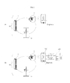
- FIG. 1(a) shows an exemplary home appliance diagnosing system that performs diagnosis on a home appliance by a method of operating a home appliance according to an embodiment of the present invention.
- a home appliance diagnosing system 10 includes a home appliance such as a laundry treating apparatus 1, a refrigerator 2, or an air conditioner 3, and a portable terminal 100 that receives a signal sound including product information output from the home appliance and diagnoses the state or failures of the home appliance based on the signal sound.
- a home appliance such as a laundry treating apparatus 1, a refrigerator 2, or an air conditioner 3, and a portable terminal 100 that receives a signal sound including product information output from the home appliance and diagnoses the state or failures of the home appliance based on the signal sound.
- Examples of the portable terminal 100 may include a mobile phone, a smart phone, a laptop computer, a PDA (Personal Digital Assistant), a tablet computer, and an e-book reader.
- smart phones having functions of both mobile phones and PDAs gain more popularity.
- smart phones have high-capacity memories and high-performance CPUs mounted therein, together with an operating system (OS) for supporting execution of various applications, process of voice/data communication and interworking with PCs. Accordingly, smart phones may more smoothly drive applications for diagnosing home appliances.
- OS operating system
- the portable terminal 100 is a smart phone, for example, the present invention is not limited thereto.
- the home appliance includes a sound output unit, such as a speaker or buzzer, which outputs a sound.
- the sound output unit reproduces information on the operation, state, or failures of the home appliance and outputs the information in the form of a predetermined sound.
- the home appliance stores product information for each of steps in which a configured operation proceeds.
- the product information may include operation information reflecting the state of an operation currently in progress, failure information when a failure occurs, and configuration information set by a user.
- the home appliance when the home appliance causes a failure or a malfunction during the operation, the home appliance stores product information including operation information, failure information, and configuration information. Accordingly, even when the home appliance abruptly stops operating due to, e.g., power outage, product information for the steps already done among the steps of the operation is already stored and may be used to determine the time up to which the operation has been performed and which steps are not performed yet.
- a user brings the portable terminal 100 closer to a sound generating portion of the home appliance, that is, the sound output unit of the home appliance and then manipulates a selecting unit of the home appliance so that a signal sound including product information is output through the sound output unit. Accordingly, the thusly output signal sound including the product information may be input to the portable terminal 100.
- the portable terminal 100 inversely extracts the product information from the received signal sound and then diagnoses the state and failures of the home appliance based on the product information. The process of diagnosing the home appliance which is performed by the portable terminal 100 will be described below in detail.
- FIG. 1 (b) shows another embodiment of a home appliance diagnosing system that performs diagnosis on a home appliance by a method of operating a portable terminal according to an embodiment of the present invention.
- the home appliance diagnosing system 20 according to the embodiment is the same as the home appliance diagnosing system 10 according to the embodiment in that the home appliance diagnosing system 20 also diagnoses a home appliance through the portable terminal 100 but differs from the home appliance diagnosing system 10 in that the portable terminal 100 communicates with a service center 200.
- the portable terminal 100 may additively receive diagnosis data from a diagnosing server of the service center 200 or may transmit a diagnosis result of the home appliance to the diagnosing server.
- the home appliance diagnosing system 20 may more specifically diagnose the home appliance using plentiful diagnosis data provided from the service center 200 and may expand database for diagnosing the home appliance since diagnosis results of the home appliance may be stored in the service center 200.
- the home appliance may output a signal sound including product information through a modulation scheme such as FSK (Frequency Shift Keying), ASK (Amplitude Shift Keying), or PSK (Phase Shift Keying).
- FSK Frequency Shift Keying
- ASK Amplitude Shift Keying
- PSK Phase Shift Keying
- the frequency of the signal sound output from the home appliance is not limited thereto and may be varied depending on the available frequency bandwidth of the sound output unit of the home appliance.
- the home appliance may output a signal sound with a frequency of about 2.6 kHz corresponding to data 0 and may output a signal sound with a frequency of about 2.8 kHz corresponding to data 1.
- data '010' has a first bit value of 0, a second bit value of 1 and a third bit value of 0, a signal sound with a frequency of about 2.6 kHz, a signal sound with a frequency of about 2.8 kHz and a signal sound with a frequency of about 2.6kHz are output in order.
- Each of the signal sound with any one of 2.6 or 2.8kHz is output during a given size of unit time, respectively.
- each bit has one symbol
- a signal sound includes plurality of frequency signal, each of the frequency signal corresponds to any one of the symbol.
- the unit time is defined as a symbol time.
- a delay may occur when the frequency signals are processed in the portable terminal 100 because resources are occupied by other applications that are being driven in the portable terminal 100, and thus, the product information may not be accurately extracted. Accordingly, it is preferred to enable a precise signal sound to be output and transferred by determining the number of pulses constituting one symbol, i.e., the number of pulses included in one frequency signal output corresponding to the symbol to thus set a symbol time. For example, it may be possible to count the number of pulses by tracing the maximum amplitude of pulses included in a frequency signal input to the portable terminal 100 and to unitize a signal according to the number of the pulses.
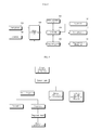
- FIG. 2 is a block diagram illustrating main elements of the portable terminal shown in FIG. 1 .
- the portable terminal 100 may include a controller 110, a signal processing unit 120, a microphone 130, a speaker 140, a diagnosing unit 150, a diagnosis data storing unit 160, a display unit 170, an input unit 180, and a communication unit 190.
- the microphone 130 receives a sound including product information output from a home appliance.
- a microphone typically prepared in the portable terminal for a calling function may be used as the microphone 130.
- the speaker 140 outputs various messages to a user while performing diagnosis on the home appliance.
- a speaker typically prepared in the portable terminal for a calling function may be used as the speaker 140.
- the signal processing unit 120 extracts product information from a sound received through the microphone 130. At this time, signal conversion performed by the signal processing unit 120 is reverse conversion of signal conversion performed by the home appliance.
- the signal processing unit 120 may convert a signal sound, which is an analogue signal with a predetermined frequency bandwidth, into digital data.
- the signal processing unit 120 may extract a control signal on a per-frame basis from the converted data and may then decode the control signal thus extracting the product information.
- the signal processing unit 120 may detect a preamble indicating the start of data including the product information, may detect the control signal including the product information based on the detected preamble, and may decode the control signal having a designated format in a decoding scheme corresponding to a product information encoding scheme of the home appliance, thereby extracting the product information of the home appliance included in the control signal.
- the diagnosing unit 150 diagnoses the operational state or failures of the home appliance by analyzing the product information extracted by the signal processing unit 120.
- the diagnosing unit 150 performs diagnosis on the home appliance by analyzing the product information through a diagnosis application.
- the diagnosis data storing unit 160 stores information on error codes of a home appliance, whether there are errors, and diagnosis data for diagnosing cause of an error and data regarding how to solve errors depending on the cause of the errors.
- the diagnosis data storing unit 160 may include various recording media such as a hard disk, a flash memory, a Read Only Memory (ROM), or a Sold State Drive (SSD).
- the input unit 180 includes at least one input means to enter a predetermined signal or data to the controller 110 by a user's manipulation, and such input means may include a touch screen that performs image displaying and command entering functions, a button-type/dial-type manipulation key or a keyboard.
- a user may drive a diagnosis application through a specific input means among the various input means provided in the input unit 180.
- the input unit 180 may include a key pad, a dome switch, or a capacitive or resistive touch pad through which commands or information may be entered by the user's pushing or touching.
- the input unit 180 may be configured as a jog wheel for rotating a key or as a manipulation type such as a jog type or a joy stick or may be configured as a finger mouse.
- this structure may be referred to as a touch screen.
- the display unit 170 displays a user interface image for each execution step of a diagnosis application.
- the display unit 170 may include, e.g., a Liquid Crystal Display (LCD) or various displays using, e.g., Light Emitting Diodes (LEDs).
- LCD Liquid Crystal Display
- LEDs Light Emitting Diodes
- the touch screen may have the functions of both the display unit 170 and the input unit 180, and in such case, a selection area displayed on a user interface image displayed on the touch screen for selection of various menus may be referred to as performing the functions of the input unit 180. Accordingly, the display unit 170 and the input unit 180 do not need to be physically separated from each other, and the other components shown in FIG. 2 are merely assigned with their names for functionally discerning one component from another, and thus, the components should be prohibited from being construed as referring to separate physical devices, respectively.
- the communication unit 190 allows for transmission of data between the portable terminal 100 and the service center 200.
- the communication unit 190 may include a mobile communication module that allows wireless signals to be transmitted/received to/from a base station, an external terminal, or a server and a wireless Internet module that allows for wireless Internet access.
- WLAN Wireless Lan
- Wi-Fi's Wibro
- Wimax Worldwide Interoperability for Microwave Access
- HSDPA High Speed Downlink Packet Access
- the controller 110 controls the operation of each of the components and the overall operation of the portable terminal 100.
- the controller 110 will be described below in greater detail together with the operation of components controlled by the controller 110.
- FIG. 3 is a view illustrating a configuration of an application driven by the portable terminal shown in FIG. 2 in order to diagnose a home appliance.
- a smart diagnosis application installed in the portable terminal 100 is provided to diagnose a home appliance.
- the smart diagnosis application provides a smart diagnosis menu for analyzing an operation state of the home appliance and advising a measurement corresponding thereto, a manual menu for describing how to use the smart diagnosis application, a demo menu for showing how the smart diagnosis application actually operates, and a introduce menu for providing information such as users' reviews or related websites' addresses.
- a signal sound including product information output from the home appliance may be recorded, the production information may be inversely extracted from the recorded signal sound, and the product information may be analyzed, thereby performing diagnosis on the home appliance.
- a result of the diagnosis may be output to be recognized by a user.
- the portable terminal may call a repair person of the service center 200 through a communication network.
- a guide image is output which includes descriptions of icons displayed on each image and manual of the smart diagnosis application.
- an image may be output which displays demos, reviews, or links to related Internet websites of the smart diagnosis application.
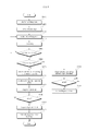
- FIG. 4 is a flowchart illustrating a method of operating a portable terminal according to an embodiment of the present invention.
- a method of operating a portable terminal may include a step of starting diagnosis on a home appliance (S310), a step of selecting the type of a product (S320), a step of outputting a recording guide (S330), a recording step (S340), a step of determining whether the recording is normally done (S350), a product diagnosing step (S360), a step of determining a diagnosis error (S370), and a step of outputting a diagnosis result (S380).
- a diagnosis on the home appliance is started in responding to a user's selection.
- the diagnosis may be initiated by the user's entry of a diagnosis application driving command through the input unit 180.
- the controller 110 performs control to enable a user interface image for conducting diagnosis of the home appliance to be displayed through the display unit 170.
- the controller 110 may display a selection menu for selecting the type of a home appliance to be diagnosed through the display unit 170.
- the controller 110 performs control that enables a manipulating method for outputting a signal sound including the product information from the home appliance selected in the product type selecting step S320 to be displayed through the display unit 170. At this time, an image of the home appliance, which indicates the position to which the portable terminal 100 needs to be brought, may be displayed together.
- a signal sound input through the microphone 130 is recorded.
- the signal sound input through the microphone 130 is transmitted to the signal processing unit 120, and the signal processing unit 120 records the signal sound.
- the controller 110 may control the display unit 170 to display recording status of the signal sound.
- the signal processing unit 120 may notify whether the recording is normally done or whether errors occurs to the controller 110. and the controller 110 may control the display unit 170 to display a result of the notification.
- the sound pressure of a signal sound being recorded in the normal recording determining step S350 may be measured, and the controller 110 may perform control to enable recording to be stopped and to enable a recording failure message to be displayed through the display unit 170 when the measured sound pressure does not reach a predetermined value. At this time, a message may be displayed which indicates that the sound pressure is too low while requesting the portable terminal 100 to be brought closer to the home appliance, that is, a position closer to the sound outputting unit that outputs the signal sound.
- the product diagnosing step S360 includes a signal processing step of extracting product information from the recorded signal sound and a diagnosing step of performing diagnosis on the home appliance based on the extracted product information.
- the signal processing unit 120 extracts product information from the signal sound completely recorded in the recording step S340.
- the diagnosing unit 150 diagnoses the home appliance based on the product information extracted in the signal processing step. At this time, diagnosis data is obtained from the diagnosis data storing unit 160, and the diagnosing unit 150 analyzes the product information by utilizing the diagnosis data.
- diagnosis error determining step S370 it is determined whether the diagnosis is accurately done in the product diagnosing step S360.
- the product information extracted from the recorded signal sound may include error data.
- the process returns to the recording guide outputting step S330 so that a user may retry to perform recording.
- a result of diagnosis on the home appliance is output.
- the controller 110 may control the display unit 170 to display a result of the diagnosis performed on the home appliance in the product diagnosing step S360.
- FIG. 5 is a flowchart illustrating a method of operating a portable terminal according to another embodiment of the present invention.
- diagnosis data may be additively obtained from a diagnosis server so that the home appliance may be diagnosed more specifically.
- diagnosis server may be provided in the service center 200.
- a home appliance diagnosing starting step S410, a product type selecting step S420, a recording guide outputting step S430, a recording step S440, a normal recording determining step S450, a diagnosis error determining step S500 and S540, and a diagnosis result outputting step S510 and S550 are substantially the same as the home appliance diagnosis starting step S310, the product type selecting step S320, the recording guide outputting step S330, the recording step S340, the normal recording determining step S350, the diagnosis error determining step S370, and the diagnosis result outputting step S380 of the embodiment, and the description thereof will be skipped.
- a simple diagnosis selecting step S460 it is selected whether to perform diagnosis on the home appliance using only the diagnosis data stored in the portable terminal 100 without receiving additional diagnosis data from the diagnosis server as in the embodiment (hereinafter, referred to as "simple diagnosis”) or to perform diagnosis on the home appliance by receiving additional diagnosis data from the diagnosis server as necessary (hereinafter, referred to as "detailed diagnosis”).
- a product diagnosing step S530 When a user selects the simple diagnosis in the simple diagnosis selecting step S460, a product diagnosing step S530, a diagnosis error determining step S540, and a diagnosis result outputting step S550 are performed.
- Such process involves performing diagnosis on the home appliance using the diagnosis data previously stored in the diagnosis data storing unit 160, and is substantially the same as the method of operating a portable terminal according to the embodiment described above.
- a server accessing step S470, a diagnosis data receiving step S480, a product diagnosing step S490, a diagnosis error determining step S500, a diagnosis result outputting step S510, and a diagnosis result transmitting step S520 are performed.
- the communication unit 190 of the portable terminal 100 is connected to the diagnosis server of the service center 200 to communicate with each other.
- diagnosis data is additively transmitted from the diagnosis server to the portable terminal 100, and based on this, the diagnosis data stored in the diagnosis data storing unit 160 is renewed. However, if the diagnosis data previously stored in the portable terminal 100 is enough to diagnose the home appliance, the diagnosis data receiving step S480 may be omitted.
- the product diagnosing step S490 is substantially the same as the product diagnosing step S360 of the embodiment except that diagnosis is performed using diagnosis data additively received in the diagnosis data receiving step S480.
- diagnosis result transmitting step S520 a result of the diagnosis performed in the product diagnosing step S490 is transmitted to the diagnosis server.
- the diagnosis result may vary depending on various factors such as operation environment, operation frequency, and operation settings that tend to be different for each user, and diagnosis results are transmitted from each user to the diagnosis server and are accumulated in the diagnosis server, so that the diagnosis data is updated to reflect various factors, which allow for more correct diagnosis when the detailed diagnosis is subsequently performed.
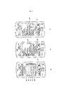
- FIGS. 6 to 11 illustrate images that are displayed through the display unit shown in FIG. 2 when performing diagnosis on a home appliance.
- description will be given with reference to FIGS. 6 to 10 .
- FIG. 6(a) shows an intro image displayed when a diagnosis application installed in the portable terminal 100 is executed.
- a manufacturer (LG) and a logo (smart laundry) are put in place. While the intro image is being displayed, the diagnosis application is loaded. While the diagnosis application is fully loaded, a main image is automatically activated.
- FIG. 6(b) illustrates an example of the main image that includes a diagnosis mode selection menu 601 and an additional information displaying menu 602.
- the selection of the diagnosis mode selection menu 601 corresponds to the home appliance diagnosis starting step of FIG. 4 or FIG. 5 . If the diagnosis mode selection menu 601 is selected, an application information displaying image may be displayed for providing information on the diagnosis application.
- FIG. 6(c) shows an example of the application information displaying image.
- the application information displaying image may include a diagnosis product information display area 605 that displays a brief description of the home appliances to be diagnosed using the diagnosis application, a demo menu 603, and a diagnosis performing menu 604.
- demo menu 603 If the demo menu 603 is selected, an image (not shown) providing a process of demonstrating diagnosis on a home appliance using the diagnosis application may be displayed.
- steps S320 to S380 of FIG. 4 or steps S420 to S550 of FIG. 5 are performed, and an image provided at each step is displayed through the display unit 170.
- predetermined menu areas 606, 607, and 608 may be displayed on a lower portion of the image displayed by the display unit 170.
- the menu areas may include a diagnosis menu 606, a user guiding menu 607, and a video link menu 608.
- the menu 606 corresponding to the current progressing state is displayed to be distinguished from the other menus 607 and 608, and depending on a menu selected by a user, an image associated with the corresponding menu is activated.
- FIG. 7(a) shows an example of an image in which a targeted home appliance for diagnosis is selected which may be displayed when the diagnosis performing menu 604 is selected.
- predetermined menus through which the type of home appliances to be diagnosable through the diagnosis application may be selected, that is, diagnosis target selection menus 701 to 703 provided for a user to be able to select the type of a home appliance desired to be diagnosed.
- the diagnosis target selection menu may include an area 701 for selecting a front load washer generally referred to as a drum-type washer in which laundry is loaded through a laundry inserting hole formed at the front side, an area 702 for selecting a top loader washer in which laundry is loaded through a laundry inserting hole formed at the top side, and an area 703 for selecting a dryer.
- Each of the images shown in FIGS. 7(b), (c), and (d) includes manual displaying areas 704, 706, and 708 for displaying a manipulating method for outputting a signal sound including product information from a targeted home appliance for diagnosis and a recording menu 705 which enables a signal sound input through the microphone 130 to be recorded when selected.
- FIG. 7(b) shows an image to be displayed when the front load washer selecting area 701 is selected and illustrates a manipulating method for outputting a signal sound including product information from the front load washer.
- the washer powers on and the portable terminal 100 is brought close to the washing/rinsing button of the washer. Then, the washing/rinsing button is left pressed for a predetermined time so as to output the signal sound including the product information, and the recording menu 705 is instructed to be selected for recording the signal sound output from the washer.
- the instruction is directed to the front load washer that outputs the signal sound including the product information through a gap where the washing/rinsing button is installed.
- FIG. 7(c) shows an image displayed when the top load washer selecting area 702 is selected and illustrates a manipulating method for outputting a signal sound including product information from the top load washer.
- the washer powers on and the portable terminal 100 is brought close to the washing/rinsing button of the washer.
- the washing/rinsing button is left pressed for a predetermined time so as to output the signal sound including the product information
- the recording menu 705 is instructed to be selected for recording the signal sound output from the washer.
- the instruction is directed to the top load washer that outputs the signal sound including the product information through a gap where the washing/rinsing button is installed.
- FIG. 7(d) shows an image displayed when the dryer selecting area 703 is selected and illustrates a manipulating method for outputting a signal sound including product information from the dryer.
- the dryer powers on and the portable terminal 100 is brought close to the washing/rinsing button (for example, when the washer comes up with drying functions). Then, the washing/rinsing button is left pressed for a predetermined time so as to output the signal sound including the product information, and the recording menu 705 is instructed to be selected for recording the signal sound output from the dryer.
- Such instruction is related to when the signal sound including the product information is output through a gap where the washing/rinsing button is installed.
- an image for the position of a specific button for outputting the signal sound including product information from a corresponding home appliance is put on each of the manipulating method displaying areas 704, 706, and 708 of FIGS. 7(b), (c), and (d) so that a user may be intuitively aware of a manipulating method through the image.
- FIG. 8 shows an example of an image activated when the recording menu 705 is selected, in which a recording progress displaying area 801 shows up on the image in the form of a pop-up window.
- a recording progress displaying area 801 may be displayed a bar-shaped icon 803 whose length increases as recording is underway and a recording canceling menu 802.
- the controller 110 may perform control to enable a message to be displayed through the display unit 170 to notify that recording has failed.
- FIG. 9 shows images in which recording has been successfully done and results of diagnosis performed on a home appliance are displayed.
- FIG. 9(a) shows an example of a product information displaying image in which product information of the home appliance is displayed.
- the product information output from the home appliance in the form of a signal sound includes an error code generated from the home appliance, operation information reflecting the operating state of the home appliance, and configuration information set by a user.
- the product information displaying image displays product information extracted from a signal sound in the diagnosing unit 150, with the product information classification.
- the product information displaying image may include error code displaying areas 901 and 902 and operation information display areas 903, 904, and 905.
- a configuration information displaying menu 906 may be displayed on the product information displaying image, and when the configuration information displaying menu 906 is selected, configuration information is displayed through the screen.
- FIG. 9(b) shows an example of an image activated when the error code displaying areas 901 and 902 or operation information display areas 903, 904, and 905 are selected.
- image may include a diagnosis result displaying area 907 and a configuration information displaying menu 906.
- the diagnosis result displaying area 907 may display detailed symptoms, cause, and solutions of a home appliance based on results of the diagnosis performed by the diagnosing unit 150.
- the same error code IE is displayed on the error code displaying areas 901 and 902 shown in FIG. 9(a) .
- the same error code is generated from the home appliance, it may be involved with various different causes. Accordingly, different detailed descriptions may be displayed through the diagnosis result displaying area 907 that is activated when each error code displaying area 901 and 902 is selected.
- each diagnosis result displaying area 907 that is activated when each operation information display area 903, 904, and 905 is selected.
- FIG. 9(c) shows an example of a configuration information display area (909) activated when a configuration information displaying menu 906 is selected.
- the configuration information display area 909 may be configured in the form of a pop-up window. On the configuration information display area 909 may be displayed information for a cycle done just before diagnosis is performed, values sensed by various sensors while the home appliance is in operation, and configuration information set by a user.
- FIG. 10 shows an example of a user guiding displaying image displayed when a user guiding menu 607 is selected.
- the user guiding displaying image may include various selecting areas 1001 to 1007.
- an image (not shown) displaying a description on a principle for diagnosing the home appliance is activated.
- an image (not shown) displaying a description on relevancy between the diagnosis of the home appliance and a portable terminal (e.g., smart phone) is activated.
- a portable terminal e.g., smart phone
- an image (1009 in FIG. 10(b) ) displaying a method of using a diagnosis application is activated.
- an image (not shown) displaying a description on when a diagnosis result shows no failure occurs to the home appliance is activated.
- an image (not shown) displaying additional information related to recording a signal sound including product information is activated.
- an image (not shown) displaying a description on a method of making use of a diagnosis demonstration (refer to 603) is activated.
- an image (not shown) displaying a description on a method of solving problems that may occur when the diagnosing system is in operation is activated.
- FIG. 11 shows images displayed when recording a signal sound including product information output from a home appliance by a portable terminal according to an embodiment of the present invention.
- embodiments of a method of operating a terminal include a recording guide outputting step S330 or S430, a recording step S340 or S440, a normal recording determining step S350 or S45, and a diagnosis error determining step S370, S500, or S540.
- FIG. 11 shows images displayed on the display unit 170 as each of the steps proceeds.
- a recording menu 1101 different in form from the recording menu 705 shown in FIG. 7 but performing substantially the same function as the recording menu 705.
- the recording step S340 or S440 is performed. At this time, a recording progress state is displayed on the screen of the display unit 170. In particular, a change in sound pressure of a signal sound including product information which is being received through the microphone 130 is displayed on the screen of the display unit 170.
- the controller 110 While recording is on, the controller 110 performs control to enable the sound pressure of a signal sound being currently recorded through the sound pressure displaying area 1102 to be displayed on the screen of the display unit 170.
- On the sound pressure displaying area 1102 may be displayed a waveform vibrating up and down as times elapse.
- the amplitude of the waveform being larger means the sound pressure is higher.
- On the sound pressure displaying area 1102 may show up two (upper and lower) sound pressure reference lines L1 and L2.
- the sound pressure reference lines L1 and L2 indicate proper levels of the sound pressure necessary for diagnosis.
- a user may leave the sound pressure at a proper level by comparing the waveform displayed on the sound pressure displaying area 1102 with the sound pressure reference lines and by adjusting the distance between the portable terminal 100 and the home appliance.
- a message 1103 may be displayed through the display unit 170 to indicate that recording has been failed. Only when a signal sound including product information received through the microphone 130 maintains a predetermined level or higher, the signal sound processing and product information extracting may be accurately conducted by the signal processing unit 120 and the diagnosing unit 150. Accordingly, when the signal sound including the product information does not have a predetermined level of sound pressure may be also known to a user, thereby inducing the user to retry to perform recording.
- a message may be displayed to indicate that recording has been succeeded.
- the recording success message may be merely the one indicating that the signal sound received through the microphone 130 has been completely recorded. Further, the recording success message may further indicate that decoding is also complete so that product information extracting and diagnosing have been finished.
- the time taken from when recording is started to when diagnosis is done is very short and what a user cares about is whether diagnosis on a home appliance has been successfully done while it is not a big deal to notify only the fact that recording has been successful with the recording separated from the diagnosing process. Accordingly, it is preferable to display the diagnosis success message 1104 after diagnosis is complete.
- FIG. 11(c) shows an image displayed when signal sound recording is successfully done but diagnosis on a home appliance is not normally done. That is, FIG. 11(c) is directed when a signal sound with a proper sound pressure necessary for product information conversion is received through the microphone 130 and recording is normally done, but a distortion occurs while the signal sound is being recorded and causes an error in the product information extracted from the signal sound. In such case, the product information converted by the signal processing unit 120 departs from a designated format, and thus, the diagnosing unit 150 cannot normally perform diagnosis. Thus, the controller 110 performs control to enable a diagnosis failure message 1105 to be displayed through the display unit 170, thus inducing a user to manipulate the home appliance again to output a signal sound including the product information and to retry to record the output signal sound.
- each image shown in FIG. 11 does not represent a manipulating method of outputting a signal sound including product information from a home appliance
- a guide for the manipulating method may be displayed on the same image together with the recording menu 1101 as shown in FIG. 7(b) to (d) .
Landscapes
- Engineering & Computer Science (AREA)
- Computer Networks & Wireless Communication (AREA)
- Signal Processing (AREA)
- Human Computer Interaction (AREA)
- Automation & Control Theory (AREA)
- Theoretical Computer Science (AREA)
- General Physics & Mathematics (AREA)
- Physics & Mathematics (AREA)
- Multimedia (AREA)
- Health & Medical Sciences (AREA)
- Audiology, Speech & Language Pathology (AREA)
- General Health & Medical Sciences (AREA)
- General Engineering & Computer Science (AREA)
- Telephone Function (AREA)
- Selective Calling Equipment (AREA)
- Cookers (AREA)
Applications Claiming Priority (3)
| Application Number | Priority Date | Filing Date | Title |
|---|---|---|---|
| KR20100140013 | 2010-12-31 | ||
| KR1020110123832A KR101275582B1 (ko) | 2010-12-31 | 2011-11-24 | 휴대 단말기의 동작방법 |
| PCT/KR2011/010098 WO2012091384A2 (fr) | 2010-12-31 | 2011-12-26 | Procédé pour faire fonctionner un terminal portable |
Publications (3)
| Publication Number | Publication Date |
|---|---|
| EP2661019A2 true EP2661019A2 (fr) | 2013-11-06 |
| EP2661019A4 EP2661019A4 (fr) | 2014-07-30 |
| EP2661019B1 EP2661019B1 (fr) | 2020-09-02 |
Family
ID=46711898
Family Applications (1)
| Application Number | Title | Priority Date | Filing Date |
|---|---|---|---|
| EP11852559.1A Active EP2661019B1 (fr) | 2010-12-31 | 2011-12-26 | Procédé pour faire fonctionner un terminal portable |
Country Status (7)
| Country | Link |
|---|---|
| US (1) | US20140006953A1 (fr) |
| EP (1) | EP2661019B1 (fr) |
| KR (1) | KR101275582B1 (fr) |
| CN (1) | CN103283183A (fr) |
| BR (1) | BR112013016650A2 (fr) |
| RU (1) | RU2573203C2 (fr) |
| WO (1) | WO2012091384A2 (fr) |
Cited By (4)
| Publication number | Priority date | Publication date | Assignee | Title |
|---|---|---|---|---|
| EP3547616A1 (fr) * | 2018-03-30 | 2019-10-02 | Orange | Procédé de gestion d'un dispositif électronique |
| EP2932340B1 (fr) | 2012-12-14 | 2019-12-04 | BSH Hausgeräte GmbH | Analyse d'un bruit émis par un appareil électroménager |
| WO2021038338A1 (fr) * | 2019-08-28 | 2021-03-04 | Carrier Corporation | Procédé et système permettant à un appareil de communiquer |
| EP4206899A1 (fr) * | 2017-05-16 | 2023-07-05 | Google LLC | Résolution de demandes d'assistant automatisé qui sont basées sur une ou plusieurs images et/ou d'autres données de capteur |
Families Citing this family (13)
| Publication number | Priority date | Publication date | Assignee | Title |
|---|---|---|---|---|
| US9417776B2 (en) * | 2012-11-27 | 2016-08-16 | Hanwha Techwin Co., Ltd. | Media reproducing apparatus and method |
| US9273878B2 (en) * | 2013-05-22 | 2016-03-01 | Honeywell International Inc. | Device interface for a building appliance |
| WO2015037333A1 (fr) * | 2013-09-10 | 2015-03-19 | 日立アプライアンス株式会社 | Système de diagnostic de climatiseur, climatiseur et terminal de communication mobile |
| CN105723635B (zh) * | 2013-09-16 | 2018-11-09 | Lg电子株式会社 | 家用电器及移动终端 |
| KR102198182B1 (ko) * | 2014-05-20 | 2021-01-04 | 엘지전자 주식회사 | 이동 단말기, 홈 어플라이언스 및 그 동작방법 |
| US11157960B2 (en) * | 2014-05-22 | 2021-10-26 | Opentv, Inc. | Targeted advertising based on user product information |
| CN104154440A (zh) * | 2014-07-29 | 2014-11-19 | 浙江生辉照明有限公司 | 智能led照明装置及智能led照明系统 |
| KR101735607B1 (ko) * | 2015-09-09 | 2017-05-15 | 엘지전자 주식회사 | 모터 구동장치, 이를 구비하는 홈 어플라이언스, 및 이동 단말기 |
| KR101709469B1 (ko) | 2015-09-11 | 2017-02-23 | 엘지전자 주식회사 | 이동 단말기, 및 홈 어플라이언스 |
| KR20170031558A (ko) * | 2015-09-11 | 2017-03-21 | 엘지전자 주식회사 | 이동 단말기, 및 홈 어플라이언스 |
| KR102509104B1 (ko) * | 2016-08-29 | 2023-03-13 | 엘지전자 주식회사 | 이동 단말기 및 이동 단말기의 동작 방법을 수행하는 프로그램이 기록된 기록 매체 |
| KR102860042B1 (ko) * | 2019-10-11 | 2025-09-16 | 엘지전자 주식회사 | 애플리캐이션을 이용한 제품 정보 제공 방법 및 장치 |
| US11410676B2 (en) * | 2020-11-18 | 2022-08-09 | Haier Us Appliance Solutions, Inc. | Sound monitoring and user assistance methods for a microwave oven |
Family Cites Families (35)
| Publication number | Priority date | Publication date | Assignee | Title |
|---|---|---|---|---|
| US7877291B2 (en) * | 1996-05-02 | 2011-01-25 | Technology Licensing Corporation | Diagnostic data interchange |
| US5987105A (en) * | 1997-06-25 | 1999-11-16 | Fisher & Paykel Limited | Appliance communication system |
| US6935335B1 (en) * | 2000-08-17 | 2005-08-30 | Ilife Systems, Inc. | System and method for treating obstructive sleep apnea |
| TW593950B (en) * | 2000-09-11 | 2004-06-21 | Toshiba Corp | Remote inspection system for refrigerator |
| JP2002253892A (ja) * | 2001-02-28 | 2002-09-10 | Hitachi Ltd | 洗濯機、表示操作パネル及びこの表示操作パネルを備えた家庭電化機器 |
| US6795799B2 (en) * | 2001-03-07 | 2004-09-21 | Qualtech Systems, Inc. | Remote diagnosis server |
| JP2002279091A (ja) * | 2001-03-16 | 2002-09-27 | Hitachi Ltd | 家電機器保守サービスシステム |
| US7010593B2 (en) * | 2001-04-30 | 2006-03-07 | Hewlett-Packard Development Company, L.P. | Dynamic generation of context-sensitive data and instructions for troubleshooting problem events in a computing environment |
| US7716058B2 (en) * | 2001-09-05 | 2010-05-11 | Voice Signal Technologies, Inc. | Speech recognition using automatic recognition turn off |
| JP2003242271A (ja) * | 2002-02-13 | 2003-08-29 | Toshiba Corp | プラント診断方法および診断システム |
| CN100409194C (zh) * | 2003-07-28 | 2008-08-06 | 高通股份有限公司 | 使用声音信道进行故障诊断、维修和升级的方法和装置 |
| US20050028034A1 (en) * | 2003-07-28 | 2005-02-03 | Alexander Gantman | Fault diagnosis, repair and upgrades using the acoustic channel |
| CN2731374Y (zh) * | 2004-03-09 | 2005-10-05 | 伊莱克斯(中国)电器有限公司 | 无线数据通讯冰箱 |
| US7828216B2 (en) * | 2005-03-11 | 2010-11-09 | Qualcomm Incorporated | Methods and apparatus for providing on-demand assistance for a wireless device |
| EP2228969B1 (fr) * | 2005-06-09 | 2017-04-19 | Whirlpool Corporation | Système d'architecture logicielle et procédé de communication correspondant, et gestion d'au moins un composant dans un appareil domestique |
| FI120716B (fi) * | 2005-12-20 | 2010-02-15 | Smart Valley Software Oy | Menetelmä ihmisen tai eläimen liikkeiden mittaamiseksi ja analysoimiseksi äänisignaalien avulla |
| US20070149886A1 (en) * | 2005-12-28 | 2007-06-28 | Kohls Mark R | ECG recording device and method of use |
| US8204189B2 (en) * | 2006-08-11 | 2012-06-19 | Fisher & Paykel Appliances Limited | Data download system and method |
| US9318108B2 (en) * | 2010-01-18 | 2016-04-19 | Apple Inc. | Intelligent automated assistant |
| KR101372266B1 (ko) * | 2007-05-16 | 2014-03-11 | 삼성전자주식회사 | 가전기기 원격 제어 시스템 및 그 제어 방법 |
| KR101404104B1 (ko) * | 2008-04-30 | 2014-06-10 | 엘지전자 주식회사 | 가전기기 진단시스템 및 그 동작방법 |
| US10827066B2 (en) * | 2008-08-28 | 2020-11-03 | The Directv Group, Inc. | Method and system for ordering content using a voice menu system |
| JP5453769B2 (ja) * | 2008-11-06 | 2014-03-26 | トヨタ自動車株式会社 | 車両用電池診断システムおよび車両用電池診断方法 |
| CA2644885C (fr) * | 2008-11-25 | 2017-01-03 | Electrolux Home Products, Inc. | Systeme et methodes etendus d'entreprise permettant de configurer, de diagnostiquer et d'actualiser des appareils |
| KR101442115B1 (ko) * | 2009-04-10 | 2014-09-18 | 엘지전자 주식회사 | 가전기기 및 가전기기 시스템 |
| US8565079B2 (en) * | 2009-04-10 | 2013-10-22 | Lg Electronics Inc. | Home appliance and home appliance system |
| KR101421685B1 (ko) * | 2009-04-10 | 2014-08-13 | 엘지전자 주식회사 | 가전기기 진단시스템 및 그 진단방법 |
| KR101579481B1 (ko) * | 2009-04-10 | 2015-12-22 | 엘지전자 주식회사 | 가전기기 진단시스템 및 그 진단방법 |
| KR101615977B1 (ko) * | 2009-05-11 | 2016-04-28 | 엘지전자 주식회사 | 에어콘을 제어하는 휴대 단말기 및 그 동작 방법 |
| KR101556972B1 (ko) * | 2009-05-11 | 2015-10-02 | 엘지전자 주식회사 | 세탁기를 제어하는 휴대 단말기 및 그 동작 방법 |
| KR101622616B1 (ko) * | 2009-05-15 | 2016-05-20 | 엘지전자 주식회사 | 공기조화기 진단방법 및 이를 수행하는 휴대 단말 장치 |
| US8412531B2 (en) * | 2009-06-10 | 2013-04-02 | Microsoft Corporation | Touch anywhere to speak |
| KR20110010374A (ko) * | 2009-07-24 | 2011-02-01 | 엘지전자 주식회사 | 가전기기 진단시스템 및 그 방법 |
| KR101472402B1 (ko) * | 2009-07-31 | 2014-12-12 | 엘지전자 주식회사 | 가전기기 진단시스템 및 그 진단방법 |
| JP2014222865A (ja) * | 2013-05-14 | 2014-11-27 | キヤノン株式会社 | 通信装置及びその制御方法、並びにプログラム |
-
2011
- 2011-11-24 KR KR1020110123832A patent/KR101275582B1/ko not_active Expired - Fee Related
- 2011-12-26 EP EP11852559.1A patent/EP2661019B1/fr active Active
- 2011-12-26 CN CN2011800638375A patent/CN103283183A/zh active Pending
- 2011-12-26 RU RU2013135713/08A patent/RU2573203C2/ru active
- 2011-12-26 US US13/977,177 patent/US20140006953A1/en not_active Abandoned
- 2011-12-26 BR BR112013016650A patent/BR112013016650A2/pt not_active Application Discontinuation
- 2011-12-26 WO PCT/KR2011/010098 patent/WO2012091384A2/fr not_active Ceased
Cited By (9)
| Publication number | Priority date | Publication date | Assignee | Title |
|---|---|---|---|---|
| EP2932340B1 (fr) | 2012-12-14 | 2019-12-04 | BSH Hausgeräte GmbH | Analyse d'un bruit émis par un appareil électroménager |
| EP2932340B2 (fr) † | 2012-12-14 | 2022-11-09 | BSH Hausgeräte GmbH | Analyse d'un bruit émis par un appareil électroménager |
| EP4206899A1 (fr) * | 2017-05-16 | 2023-07-05 | Google LLC | Résolution de demandes d'assistant automatisé qui sont basées sur une ou plusieurs images et/ou d'autres données de capteur |
| US11734926B2 (en) | 2017-05-16 | 2023-08-22 | Google Llc | Resolving automated assistant requests that are based on image(s) and/or other sensor data |
| US12499679B2 (en) | 2017-05-16 | 2025-12-16 | Google Llc | Resolving automated assistant requests that are based on image(s) and/or other sensor data |
| EP3547616A1 (fr) * | 2018-03-30 | 2019-10-02 | Orange | Procédé de gestion d'un dispositif électronique |
| FR3079643A1 (fr) * | 2018-03-30 | 2019-10-04 | Orange | Procede de gestion d'un dispositif electronique. |
| US11330318B2 (en) | 2018-03-30 | 2022-05-10 | Orange | Method for managing an electronic device |
| WO2021038338A1 (fr) * | 2019-08-28 | 2021-03-04 | Carrier Corporation | Procédé et système permettant à un appareil de communiquer |
Also Published As
| Publication number | Publication date |
|---|---|
| WO2012091384A3 (fr) | 2012-12-06 |
| KR101275582B1 (ko) | 2013-06-17 |
| RU2013135713A (ru) | 2015-02-10 |
| CN103283183A (zh) | 2013-09-04 |
| WO2012091384A2 (fr) | 2012-07-05 |
| RU2573203C2 (ru) | 2016-01-20 |
| AU2011350230B2 (en) | 2015-10-01 |
| KR20120078585A (ko) | 2012-07-10 |
| US20140006953A1 (en) | 2014-01-02 |
| BR112013016650A2 (pt) | 2016-10-04 |
| EP2661019A4 (fr) | 2014-07-30 |
| AU2011350230A1 (en) | 2013-08-01 |
| EP2661019B1 (fr) | 2020-09-02 |
Similar Documents
| Publication | Publication Date | Title |
|---|---|---|
| EP2661019A2 (fr) | Procédé pour faire fonctionner un terminal portable | |
| EP2555474B1 (fr) | Appareil domestique, système de diagnostic pour un appareil domestique et procédé | |
| US20230028729A1 (en) | Voice recognition system, server, display apparatus and control methods thereof | |
| US20220394348A1 (en) | System and method for using a virtual agent to provide consumer electronic device related technical support | |
| EP3627336B1 (fr) | Procédé et appareil de partage de contenus entre des dispositifs | |
| CN104104565B (zh) | 家用电器及其控制方法、家用电器系统及其控制方法 | |
| CN107466077B (zh) | 一种网络切换方法及移动终端 | |
| EP2560324B1 (fr) | Appareil de diagnostic et procédé pour un appareil ménager | |
| EP2685438A2 (fr) | Appareil domestique et son système | |
| EP2367147A1 (fr) | Système de fourniture de service en ligne, procédé, serveur et son dispositif mobile, et produit de programme informatique | |
| JP2012532558A (ja) | 家電機器診断システム及びその運転方法 | |
| KR20110010375A (ko) | 가전기기 진단 시스템 및 그 진단방법 | |
| CN114565070B (zh) | 一种标签绑定方法、装置及移动终端 | |
| US8874962B2 (en) | Diagnostic handling server using dissatisfying item data | |
| KR101416938B1 (ko) | 가전기기, 진단장치 및 그 진단방법 | |
| US8700960B2 (en) | Diagnostic code generation terminal, diagnostic method and program for diagnostic code generation terminal | |
| CN118631638A (zh) | 智能设备配网方法、系统、计算机设备及可读存储介质 | |
| CN117807339A (zh) | 一种显示设备及通过浏览器加载网页的方法 | |
| CN114390436A (zh) | 设备控制方法、装置、存储介质及电子设备 | |
| CN113810771A (zh) | 一种显示设备及网络连接诊断结果的显示方法 | |
| CN118260151A (zh) | 一种日志文件的获取方法及显示设备、服务器 |
Legal Events
| Date | Code | Title | Description |
|---|---|---|---|
| PUAI | Public reference made under article 153(3) epc to a published international application that has entered the european phase |
Free format text: ORIGINAL CODE: 0009012 |
|
| 17P | Request for examination filed |
Effective date: 20130731 |
|
| AK | Designated contracting states |
Kind code of ref document: A2 Designated state(s): AL AT BE BG CH CY CZ DE DK EE ES FI FR GB GR HR HU IE IS IT LI LT LU LV MC MK MT NL NO PL PT RO RS SE SI SK SM TR |
|
| DAX | Request for extension of the european patent (deleted) | ||
| A4 | Supplementary search report drawn up and despatched |
Effective date: 20140630 |
|
| RIC1 | Information provided on ipc code assigned before grant |
Ipc: G06F 3/16 20060101ALI20140624BHEP Ipc: H04L 12/28 20060101AFI20140624BHEP |
|
| STAA | Information on the status of an ep patent application or granted ep patent |
Free format text: STATUS: EXAMINATION IS IN PROGRESS |
|
| 17Q | First examination report despatched |
Effective date: 20171214 |
|
| GRAP | Despatch of communication of intention to grant a patent |
Free format text: ORIGINAL CODE: EPIDOSNIGR1 |
|
| STAA | Information on the status of an ep patent application or granted ep patent |
Free format text: STATUS: GRANT OF PATENT IS INTENDED |
|
| INTG | Intention to grant announced |
Effective date: 20200421 |
|
| GRAS | Grant fee paid |
Free format text: ORIGINAL CODE: EPIDOSNIGR3 |
|
| GRAA | (expected) grant |
Free format text: ORIGINAL CODE: 0009210 |
|
| STAA | Information on the status of an ep patent application or granted ep patent |
Free format text: STATUS: THE PATENT HAS BEEN GRANTED |
|
| AK | Designated contracting states |
Kind code of ref document: B1 Designated state(s): AL AT BE BG CH CY CZ DE DK EE ES FI FR GB GR HR HU IE IS IT LI LT LU LV MC MK MT NL NO PL PT RO RS SE SI SK SM TR |
|
| REG | Reference to a national code |
Ref country code: GB Ref legal event code: FG4D |
|
| REG | Reference to a national code |
Ref country code: AT Ref legal event code: REF Ref document number: 1310086 Country of ref document: AT Kind code of ref document: T Effective date: 20200915 Ref country code: CH Ref legal event code: EP |
|
| REG | Reference to a national code |
Ref country code: DE Ref legal event code: R096 Ref document number: 602011068494 Country of ref document: DE |
|
| REG | Reference to a national code |
Ref country code: IE Ref legal event code: FG4D |
|
| REG | Reference to a national code |
Ref country code: LT Ref legal event code: MG4D |
|
| PG25 | Lapsed in a contracting state [announced via postgrant information from national office to epo] |
Ref country code: LT Free format text: LAPSE BECAUSE OF FAILURE TO SUBMIT A TRANSLATION OF THE DESCRIPTION OR TO PAY THE FEE WITHIN THE PRESCRIBED TIME-LIMIT Effective date: 20200902 Ref country code: HR Free format text: LAPSE BECAUSE OF FAILURE TO SUBMIT A TRANSLATION OF THE DESCRIPTION OR TO PAY THE FEE WITHIN THE PRESCRIBED TIME-LIMIT Effective date: 20200902 Ref country code: BG Free format text: LAPSE BECAUSE OF FAILURE TO SUBMIT A TRANSLATION OF THE DESCRIPTION OR TO PAY THE FEE WITHIN THE PRESCRIBED TIME-LIMIT Effective date: 20201202 Ref country code: FI Free format text: LAPSE BECAUSE OF FAILURE TO SUBMIT A TRANSLATION OF THE DESCRIPTION OR TO PAY THE FEE WITHIN THE PRESCRIBED TIME-LIMIT Effective date: 20200902 Ref country code: NO Free format text: LAPSE BECAUSE OF FAILURE TO SUBMIT A TRANSLATION OF THE DESCRIPTION OR TO PAY THE FEE WITHIN THE PRESCRIBED TIME-LIMIT Effective date: 20201202 Ref country code: GR Free format text: LAPSE BECAUSE OF FAILURE TO SUBMIT A TRANSLATION OF THE DESCRIPTION OR TO PAY THE FEE WITHIN THE PRESCRIBED TIME-LIMIT Effective date: 20201203 Ref country code: SE Free format text: LAPSE BECAUSE OF FAILURE TO SUBMIT A TRANSLATION OF THE DESCRIPTION OR TO PAY THE FEE WITHIN THE PRESCRIBED TIME-LIMIT Effective date: 20200902 |
|
| REG | Reference to a national code |
Ref country code: NL Ref legal event code: MP Effective date: 20200902 |
|
| REG | Reference to a national code |
Ref country code: AT Ref legal event code: MK05 Ref document number: 1310086 Country of ref document: AT Kind code of ref document: T Effective date: 20200902 |
|
| PG25 | Lapsed in a contracting state [announced via postgrant information from national office to epo] |
Ref country code: RS Free format text: LAPSE BECAUSE OF FAILURE TO SUBMIT A TRANSLATION OF THE DESCRIPTION OR TO PAY THE FEE WITHIN THE PRESCRIBED TIME-LIMIT Effective date: 20200902 Ref country code: PL Free format text: LAPSE BECAUSE OF FAILURE TO SUBMIT A TRANSLATION OF THE DESCRIPTION OR TO PAY THE FEE WITHIN THE PRESCRIBED TIME-LIMIT Effective date: 20200902 Ref country code: LV Free format text: LAPSE BECAUSE OF FAILURE TO SUBMIT A TRANSLATION OF THE DESCRIPTION OR TO PAY THE FEE WITHIN THE PRESCRIBED TIME-LIMIT Effective date: 20200902 |
|
| PG25 | Lapsed in a contracting state [announced via postgrant information from national office to epo] |
Ref country code: SM Free format text: LAPSE BECAUSE OF FAILURE TO SUBMIT A TRANSLATION OF THE DESCRIPTION OR TO PAY THE FEE WITHIN THE PRESCRIBED TIME-LIMIT Effective date: 20200902 Ref country code: RO Free format text: LAPSE BECAUSE OF FAILURE TO SUBMIT A TRANSLATION OF THE DESCRIPTION OR TO PAY THE FEE WITHIN THE PRESCRIBED TIME-LIMIT Effective date: 20200902 Ref country code: PT Free format text: LAPSE BECAUSE OF FAILURE TO SUBMIT A TRANSLATION OF THE DESCRIPTION OR TO PAY THE FEE WITHIN THE PRESCRIBED TIME-LIMIT Effective date: 20210104 Ref country code: NL Free format text: LAPSE BECAUSE OF FAILURE TO SUBMIT A TRANSLATION OF THE DESCRIPTION OR TO PAY THE FEE WITHIN THE PRESCRIBED TIME-LIMIT Effective date: 20200902 Ref country code: EE Free format text: LAPSE BECAUSE OF FAILURE TO SUBMIT A TRANSLATION OF THE DESCRIPTION OR TO PAY THE FEE WITHIN THE PRESCRIBED TIME-LIMIT Effective date: 20200902 Ref country code: CZ Free format text: LAPSE BECAUSE OF FAILURE TO SUBMIT A TRANSLATION OF THE DESCRIPTION OR TO PAY THE FEE WITHIN THE PRESCRIBED TIME-LIMIT Effective date: 20200902 |
|
| PG25 | Lapsed in a contracting state [announced via postgrant information from national office to epo] |
Ref country code: AT Free format text: LAPSE BECAUSE OF FAILURE TO SUBMIT A TRANSLATION OF THE DESCRIPTION OR TO PAY THE FEE WITHIN THE PRESCRIBED TIME-LIMIT Effective date: 20200902 Ref country code: AL Free format text: LAPSE BECAUSE OF FAILURE TO SUBMIT A TRANSLATION OF THE DESCRIPTION OR TO PAY THE FEE WITHIN THE PRESCRIBED TIME-LIMIT Effective date: 20200902 Ref country code: ES Free format text: LAPSE BECAUSE OF FAILURE TO SUBMIT A TRANSLATION OF THE DESCRIPTION OR TO PAY THE FEE WITHIN THE PRESCRIBED TIME-LIMIT Effective date: 20200902 Ref country code: IS Free format text: LAPSE BECAUSE OF FAILURE TO SUBMIT A TRANSLATION OF THE DESCRIPTION OR TO PAY THE FEE WITHIN THE PRESCRIBED TIME-LIMIT Effective date: 20210102 |
|
| REG | Reference to a national code |
Ref country code: DE Ref legal event code: R097 Ref document number: 602011068494 Country of ref document: DE |
|
| PG25 | Lapsed in a contracting state [announced via postgrant information from national office to epo] |
Ref country code: SK Free format text: LAPSE BECAUSE OF FAILURE TO SUBMIT A TRANSLATION OF THE DESCRIPTION OR TO PAY THE FEE WITHIN THE PRESCRIBED TIME-LIMIT Effective date: 20200902 |
|
| PLBE | No opposition filed within time limit |
Free format text: ORIGINAL CODE: 0009261 |
|
| STAA | Information on the status of an ep patent application or granted ep patent |
Free format text: STATUS: NO OPPOSITION FILED WITHIN TIME LIMIT |
|
| REG | Reference to a national code |
Ref country code: CH Ref legal event code: PL |
|
| 26N | No opposition filed |
Effective date: 20210603 |
|
| GBPC | Gb: european patent ceased through non-payment of renewal fee |
Effective date: 20201226 |
|
| PG25 | Lapsed in a contracting state [announced via postgrant information from national office to epo] |
Ref country code: MC Free format text: LAPSE BECAUSE OF FAILURE TO SUBMIT A TRANSLATION OF THE DESCRIPTION OR TO PAY THE FEE WITHIN THE PRESCRIBED TIME-LIMIT Effective date: 20200902 Ref country code: DK Free format text: LAPSE BECAUSE OF FAILURE TO SUBMIT A TRANSLATION OF THE DESCRIPTION OR TO PAY THE FEE WITHIN THE PRESCRIBED TIME-LIMIT Effective date: 20200902 Ref country code: SI Free format text: LAPSE BECAUSE OF FAILURE TO SUBMIT A TRANSLATION OF THE DESCRIPTION OR TO PAY THE FEE WITHIN THE PRESCRIBED TIME-LIMIT Effective date: 20200902 |
|
| REG | Reference to a national code |
Ref country code: BE Ref legal event code: MM Effective date: 20201231 |
|
| PG25 | Lapsed in a contracting state [announced via postgrant information from national office to epo] |
Ref country code: IE Free format text: LAPSE BECAUSE OF NON-PAYMENT OF DUE FEES Effective date: 20201226 Ref country code: IT Free format text: LAPSE BECAUSE OF FAILURE TO SUBMIT A TRANSLATION OF THE DESCRIPTION OR TO PAY THE FEE WITHIN THE PRESCRIBED TIME-LIMIT Effective date: 20200902 Ref country code: LU Free format text: LAPSE BECAUSE OF NON-PAYMENT OF DUE FEES Effective date: 20201226 Ref country code: FR Free format text: LAPSE BECAUSE OF NON-PAYMENT OF DUE FEES Effective date: 20201231 |
|
| PG25 | Lapsed in a contracting state [announced via postgrant information from national office to epo] |
Ref country code: CH Free format text: LAPSE BECAUSE OF NON-PAYMENT OF DUE FEES Effective date: 20201231 Ref country code: GB Free format text: LAPSE BECAUSE OF NON-PAYMENT OF DUE FEES Effective date: 20201226 Ref country code: LI Free format text: LAPSE BECAUSE OF NON-PAYMENT OF DUE FEES Effective date: 20201231 |
|
| PG25 | Lapsed in a contracting state [announced via postgrant information from national office to epo] |
Ref country code: IS Free format text: LAPSE BECAUSE OF FAILURE TO SUBMIT A TRANSLATION OF THE DESCRIPTION OR TO PAY THE FEE WITHIN THE PRESCRIBED TIME-LIMIT Effective date: 20210102 Ref country code: TR Free format text: LAPSE BECAUSE OF FAILURE TO SUBMIT A TRANSLATION OF THE DESCRIPTION OR TO PAY THE FEE WITHIN THE PRESCRIBED TIME-LIMIT Effective date: 20200902 Ref country code: MT Free format text: LAPSE BECAUSE OF FAILURE TO SUBMIT A TRANSLATION OF THE DESCRIPTION OR TO PAY THE FEE WITHIN THE PRESCRIBED TIME-LIMIT Effective date: 20200902 Ref country code: CY Free format text: LAPSE BECAUSE OF FAILURE TO SUBMIT A TRANSLATION OF THE DESCRIPTION OR TO PAY THE FEE WITHIN THE PRESCRIBED TIME-LIMIT Effective date: 20200902 |
|
| PG25 | Lapsed in a contracting state [announced via postgrant information from national office to epo] |
Ref country code: MK Free format text: LAPSE BECAUSE OF FAILURE TO SUBMIT A TRANSLATION OF THE DESCRIPTION OR TO PAY THE FEE WITHIN THE PRESCRIBED TIME-LIMIT Effective date: 20200902 |
|
| PG25 | Lapsed in a contracting state [announced via postgrant information from national office to epo] |
Ref country code: BE Free format text: LAPSE BECAUSE OF NON-PAYMENT OF DUE FEES Effective date: 20201231 |
|
| PGFP | Annual fee paid to national office [announced via postgrant information from national office to epo] |
Ref country code: DE Payment date: 20251105 Year of fee payment: 15 |