EP2661033A2 - Strahlenwechsel-Anzeige zur Kanalschätzungsverbesserung in drahtlosen Netzwerken - Google Patents
Strahlenwechsel-Anzeige zur Kanalschätzungsverbesserung in drahtlosen Netzwerken Download PDFInfo
- Publication number
- EP2661033A2 EP2661033A2 EP20130166194 EP13166194A EP2661033A2 EP 2661033 A2 EP2661033 A2 EP 2661033A2 EP 20130166194 EP20130166194 EP 20130166194 EP 13166194 A EP13166194 A EP 13166194A EP 2661033 A2 EP2661033 A2 EP 2661033A2
- Authority
- EP
- European Patent Office
- Prior art keywords
- channel
- channel estimation
- training field
- response matrix
- change
- Prior art date
- Legal status (The legal status is an assumption and is not a legal conclusion. Google has not performed a legal analysis and makes no representation as to the accuracy of the status listed.)
- Granted
Links
Images




Classifications
-
- H—ELECTRICITY
- H04—ELECTRIC COMMUNICATION TECHNIQUE
- H04W—WIRELESS COMMUNICATION NETWORKS
- H04W24/00—Supervisory, monitoring or testing arrangements
- H04W24/02—Arrangements for optimising operational condition
-
- H—ELECTRICITY
- H04—ELECTRIC COMMUNICATION TECHNIQUE
- H04L—TRANSMISSION OF DIGITAL INFORMATION, e.g. TELEGRAPHIC COMMUNICATION
- H04L25/00—Baseband systems
- H04L25/02—Details ; arrangements for supplying electrical power along data transmission lines
- H04L25/0202—Channel estimation
- H04L25/0204—Channel estimation of multiple channels
-
- H—ELECTRICITY
- H04—ELECTRIC COMMUNICATION TECHNIQUE
- H04B—TRANSMISSION
- H04B7/00—Radio transmission systems, i.e. using radiation field
- H04B7/02—Diversity systems; Multi-antenna system, i.e. transmission or reception using multiple antennas
- H04B7/04—Diversity systems; Multi-antenna system, i.e. transmission or reception using multiple antennas using two or more spaced independent antennas
- H04B7/06—Diversity systems; Multi-antenna system, i.e. transmission or reception using multiple antennas using two or more spaced independent antennas at the transmitting station
- H04B7/0613—Diversity systems; Multi-antenna system, i.e. transmission or reception using multiple antennas using two or more spaced independent antennas at the transmitting station using simultaneous transmission
- H04B7/0615—Diversity systems; Multi-antenna system, i.e. transmission or reception using multiple antennas using two or more spaced independent antennas at the transmitting station using simultaneous transmission of weighted versions of same signal
- H04B7/0617—Diversity systems; Multi-antenna system, i.e. transmission or reception using multiple antennas using two or more spaced independent antennas at the transmitting station using simultaneous transmission of weighted versions of same signal for beam forming
-
- H—ELECTRICITY
- H04—ELECTRIC COMMUNICATION TECHNIQUE
- H04B—TRANSMISSION
- H04B7/00—Radio transmission systems, i.e. using radiation field
- H04B7/02—Diversity systems; Multi-antenna system, i.e. transmission or reception using multiple antennas
- H04B7/04—Diversity systems; Multi-antenna system, i.e. transmission or reception using multiple antennas using two or more spaced independent antennas
- H04B7/06—Diversity systems; Multi-antenna system, i.e. transmission or reception using multiple antennas using two or more spaced independent antennas at the transmitting station
- H04B7/0613—Diversity systems; Multi-antenna system, i.e. transmission or reception using multiple antennas using two or more spaced independent antennas at the transmitting station using simultaneous transmission
- H04B7/0615—Diversity systems; Multi-antenna system, i.e. transmission or reception using multiple antennas using two or more spaced independent antennas at the transmitting station using simultaneous transmission of weighted versions of same signal
- H04B7/0619—Diversity systems; Multi-antenna system, i.e. transmission or reception using multiple antennas using two or more spaced independent antennas at the transmitting station using simultaneous transmission of weighted versions of same signal using feedback from receiving side
- H04B7/0621—Feedback content
- H04B7/0626—Channel coefficients, e.g. channel state information [CSI]
-
- H—ELECTRICITY
- H04—ELECTRIC COMMUNICATION TECHNIQUE
- H04B—TRANSMISSION
- H04B7/00—Radio transmission systems, i.e. using radiation field
- H04B7/02—Diversity systems; Multi-antenna system, i.e. transmission or reception using multiple antennas
- H04B7/04—Diversity systems; Multi-antenna system, i.e. transmission or reception using multiple antennas using two or more spaced independent antennas
- H04B7/06—Diversity systems; Multi-antenna system, i.e. transmission or reception using multiple antennas using two or more spaced independent antennas at the transmitting station
- H04B7/0686—Hybrid systems, i.e. switching and simultaneous transmission
- H04B7/0695—Hybrid systems, i.e. switching and simultaneous transmission using beam selection
- H04B7/06952—Selecting one or more beams from a plurality of beams, e.g. beam training, management or sweeping
-
- H—ELECTRICITY
- H04—ELECTRIC COMMUNICATION TECHNIQUE
- H04L—TRANSMISSION OF DIGITAL INFORMATION, e.g. TELEGRAPHIC COMMUNICATION
- H04L25/00—Baseband systems
- H04L25/02—Details ; arrangements for supplying electrical power along data transmission lines
- H04L25/0202—Channel estimation
- H04L25/0224—Channel estimation using sounding signals
- H04L25/0228—Channel estimation using sounding signals with direct estimation from sounding signals
-
- H—ELECTRICITY
- H04—ELECTRIC COMMUNICATION TECHNIQUE
- H04L—TRANSMISSION OF DIGITAL INFORMATION, e.g. TELEGRAPHIC COMMUNICATION
- H04L5/00—Arrangements affording multiple use of the transmission path
- H04L5/003—Arrangements for allocating sub-channels of the transmission path
- H04L5/0048—Allocation of pilot signals, i.e. of signals known to the receiver
-
- H—ELECTRICITY
- H04—ELECTRIC COMMUNICATION TECHNIQUE
- H04B—TRANSMISSION
- H04B7/00—Radio transmission systems, i.e. using radiation field
- H04B7/02—Diversity systems; Multi-antenna system, i.e. transmission or reception using multiple antennas
- H04B7/04—Diversity systems; Multi-antenna system, i.e. transmission or reception using multiple antennas using two or more spaced independent antennas
- H04B7/0413—MIMO systems
-
- H—ELECTRICITY
- H04—ELECTRIC COMMUNICATION TECHNIQUE
- H04B—TRANSMISSION
- H04B7/00—Radio transmission systems, i.e. using radiation field
- H04B7/02—Diversity systems; Multi-antenna system, i.e. transmission or reception using multiple antennas
- H04B7/04—Diversity systems; Multi-antenna system, i.e. transmission or reception using multiple antennas using two or more spaced independent antennas
- H04B7/06—Diversity systems; Multi-antenna system, i.e. transmission or reception using multiple antennas using two or more spaced independent antennas at the transmitting station
- H04B7/0613—Diversity systems; Multi-antenna system, i.e. transmission or reception using multiple antennas using two or more spaced independent antennas at the transmitting station using simultaneous transmission
- H04B7/0615—Diversity systems; Multi-antenna system, i.e. transmission or reception using multiple antennas using two or more spaced independent antennas at the transmitting station using simultaneous transmission of weighted versions of same signal
- H04B7/0619—Diversity systems; Multi-antenna system, i.e. transmission or reception using multiple antennas using two or more spaced independent antennas at the transmitting station using simultaneous transmission of weighted versions of same signal using feedback from receiving side
-
- H—ELECTRICITY
- H04—ELECTRIC COMMUNICATION TECHNIQUE
- H04L—TRANSMISSION OF DIGITAL INFORMATION, e.g. TELEGRAPHIC COMMUNICATION
- H04L25/00—Baseband systems
- H04L25/02—Details ; arrangements for supplying electrical power along data transmission lines
- H04L25/03—Shaping networks in transmitter or receiver, e.g. adaptive shaping networks
- H04L25/03006—Arrangements for removing intersymbol interference
- H04L2025/03777—Arrangements for removing intersymbol interference characterised by the signalling
- H04L2025/03783—Details of reference signals
Definitions
- the disclosed embodiments relate generally to wireless network communications, and, more particularly, to beam-change indication for channel estimation improvement in wireless communications systems.
- CSI channel state information
- This information describes how a signal propagates from the transmitter to the receiver and represents the combined effect of, for example, scattering, fading, and power decay with distance.
- the CSI makes it possible to adapt transmissions to current channel conditions, which is crucial for achieving reliable communication with high data rates in multi-antenna systems.
- CSI needs to be estimated at the receiver and usually quantized and feedback to the transmitter. Since the channel condition varies, instantaneous CSI needs to be estimated on a short-term basis.
- a popular approach is so-called training sequence (or pilot sequence), where a known signal is transmitted and a channel response matrix H is estimated using the combined knowledge of the transmitted and the received signal.
- Channel estimation inaccuracy is one key factor that degrades the performance of wireless networks.
- various methods of enhancing channel estimation accuracy have been widely used. For example, channel smoothing when the channels of adjacent sub-carriers are similar, data-aided feedback channel tracking when complexity and latency are not critical, and pilots-based channel tracking when pilots are enough.
- IEEE 802.11 is a set of standards for implementing wireless local area network (WLAN) communication in the 2.4, 3.6, 5, and 60GHz frequency bands.
- IEEE 802.11ac covers very high throughput with potential improvements over IEEE 802.11n, while upcoming IEEE 802.11ah covers Sub 1GHz sensor network and smart metering.
- a useful method is proposed to enhance channel estimation performance based on the IEEE 802.11ac and the upcoming IEEE 802.1ah standards.
- a method of channel estimation enhancement is provided.
- a transmitting device transmits a long preamble frame comprising a first training field, a signal field, and a second training field.
- the transmitting devices applies a first set of beam-steering matrices to a first training sequence and generates the first training filed, and applies a second set of beam-steering matrices to a second training sequence to generate the second training field.
- the signal field has a beam-change indication bit indicates whether there is beam change between the first training field and the second training field.
- the beam-change indication bit is determined by comparing the first set of beam-steering matrices and the second set of beam-steering matrices for all subcarriers. If the matrices are equal for all subcarriers, then the indication bit is set to zero indicating no beam change between the two training fields.
- a receiving device receives the long preamble frame, performs a first channel estimation based on the received first training field, and performs a second channel estimation based on the received second training field.
- the receiving device also decodes the beam-change indication bit from the received signal field. If the beam-change indication bit indicates no beam change, then the receiving device performs channel estimation enhancement by combining the first channel estimation and the second channel estimation. As a result, channel estimation performance is improved.
- the beam-change indication bit is also used to determine whether to apply channel smoothing.
- Figure 1 illustrates a wireless communications system and a long preamble frame structure in accordance with a novel aspect.
- Figure 2 is a diagram of a long preamble frame and a signal field of the long preamble frame.
- Figure 3 is a simplified block diagram of a wireless transmitting device and a receiving device in accordance with a novel aspect.
- Figure 4 is a diagram of a transmitting device that inserts a beam-change indicator.
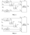
- Figure 5 is a first embodiment of a receiving device that performs channel estimation enhancement based on a beam-change indicator.
- Figure 6 is a second embodiment of a receiving device that performs channel estimation enhancement based on a beam-change indicator.
- Figure 7 is a third embodiment of a receiving device that performs channel estimation enhancement based on a beam-change indicator.
- Figure 8 is flow chart of a method of transmitting and encoding a long preamble frame with a beam-change indicator in accordance with a novel aspect.
- Figure 9 is a flow chart of a method of receiving a long preamble frame and perform channel estimation enhancement in accordance with a novel aspect.
- FIG. 1 illustrates a wireless communications network 100 and a long preamble frame 110 in accordance with one novel aspect.
- Wireless communications network 100 comprises a wireless access point AP 101 and a wireless station STA 102.
- wireless devices communicate with each other through various well-defined frame structures.
- a frame comprises a Physical Layer Convergence Procedure (PLCP) Protocol Data Unit (PPDU), a frame header, and a payload.
- PLCP Physical Layer Convergence Procedure
- PPDU Protocol Data Unit
- Frames are in turn divided into very specific and standardized sections. For example, in the upcoming IEEE 802.11ah standard, a transmitter is required to be able to transmit a long preamble frame structure over 2MHz, 4MHz, 6MHz, 8MHz, and 16MHz channels.
- a long preamble frame 110 is transmitted from AP 101 to STA 102.
- Long preamble frame 110 comprises a short training field (STF 111), a long training field (LTF 112), a signal A field (SIG-A 113), a short training field for data (D-STF 114), a long training field for data (D-LTF 115), a signal B field (SIG-B 116), and data 117.
- LTF 112 is used for channel estimation and the decoding of SIG-A at the receiver side
- D-LTF 115 is used for channel estimation and the decoding of SIG-B and data at the receiver side.
- beam steering matrices can be applied to the long preamble frame for beamforming to achieve spatial expansion or other purposes.
- two different sets of beam steering matrices are typically applied. For example, a first set of beam steering matrices W(k) is applied to each subcarrier k of fields STF, LTF, and SIG-A (e.g., those fields are also referred to as the Omni portion of the long preamble frame).
- a second set of beam steering matrices Q(k) is applied to each subcarrier k of fields D-STF, D-LTF, SIG-B, and data (e.g., also referred to as the Data portion of the long preamble frame).
- the dimension of W(k) and Q(k) is related to the number of antenna and the number of data streams to be transmitted in a corresponding MIMO scheme.
- the beam steering matrices W(k) and Q(k) may either be the same or different. This is because W(k) may be a column vector with N-th TX antenna elements with element i TX being exp - j ⁇ 2 ⁇ ⁇ ⁇ k ⁇ ⁇ F ⁇ T CS i TX , where T CS i TX represents the cyclic shift for transmitter chain i TX (e.g., for Omni-directional transmission), while Q(k) may be precoding matrices (e.g., for MIMO beamforming transmission) based on previous channel sounding feedback.
- the beam steering matrices W(k) and Q(k) may be exactly the same under certain scenarios.
- both W(k) and Q(k) are identity matrices I(k). Therefore, for the same communication link between a transmitter and a receiver, the channel condition for transmitting STF, LTF, SIG-A and the channel conditicn for transmitting D-STF, D-LTF, SIG-B, and data, may either be the same or different, depending on W(k) and Q(k).
- channel estimation is performed based on received LTF and D-LTF symbols. If the beam steering matrices W(k) and Q(k) are the same, then the channel condition used to transmit STF, LTF, SIG-A is the same as the channel condition used to transmit D-STF, D-LTF, SIG-B, and data. Traditionally, channel estimation for data is performed only based on D-LTF symbols. In one novel aspect, the channel estimation for data can be enhanced by utilizing channel estimation based on both LTF and D-LTF symbols if the channel condition (e.g., the beam steering matrices) has not been changed by the transmitter. In one embodiment, as illustrated in Figure 1 , a beam-change indicator is inserted by AP 101 at the transmitter side, and at the receiver side, STA 102 decodes the beam-change indicator from the signal field to achieve channel estimation enhancement.
- the channel condition e.g., the beam steering matrices
- Figure 2 is a diagram of a long preamble frame structure and a signal field of the long preamble frame.
- Table 201 lists all the fields including a signal A filed SIG-A of the long preamble frame.
- SIG-A single user
- Table 202 lists the structure inside a first SIG-A-1 symbol.
- SIG-A-1 symbol includes a one-bit MU/SU field, a one-bit STBC field, a one-bit reserved field, a two-bit bandwidth (BW), a two-bit number of STS (N STS ), a nine-but partial AID, a one-bit short guard interval, a two-bit coding, a four-bit MCS index, and a one-bit beam-change indication.
- the one-bit beam-change indication field indicates whether the beam steering matrices Q(k) have been changed. For example, a value of zero(0) indicates that the beam steering matrices are identical, and a value of one(1) indicates that the beam steering matrices have been changed across Omni and Data portions of the long preamble.
- the beam-change indication bit can also be used as an indication for channel smoothing. If beam-change indication bit is set to zero, the receiver may do channel smoothing. Otherwise, smoothing is not recommended.
- FIG. 3 is a simplified block diagram of wireless devices 301 and 311 in accordance with a novel aspect.
- antennae 307 and 308 transmit and receive radio signals.
- RF transceiver 306 also converts received baseband signals from the processor, converts them to RF signals, and sends out to antennae 307.
- Processor 303 processes the received baseband signals and invokes different functional modules to perform features in wireless device 301.
- Memory 302 stores program instructions and data 310 to control the operations of the wireless device.
- RF transceiver module 316 coupled with the antennae, receives RF signals from the antennae, converts them to baseband signals and sends them to processor 313.
- the RF transceiver 316 also converts received baseband signals from the processor, converts them to RF signals, and sends out to antennae 317.
- Processor 313 processes the received baseband signals and invokes different functional modules to perform features in wireless device 311.
- Memory 312 stores program instructions and data 320 to control the operations of the wireless device.
- wireless devices 301 and 311 also include several functional modules to perform embodiments of the present invention.
- wireless device 301 is a transmitting device that includes an encoder 305, a beamforming module 304, and a feedback module 309.
- Wireless device 311 is a receiving device that includes a decoder 315, a channel estimation module 314, and a feedback module 319. Note that a wireless device may be both transmitting and receiving device.
- the different functional modules can be implemented by software, firmware, hardware, or any combination thereof.
- the function modules when executed by the processors 303 and 313 (e.g., via executing program codes 310 and 320), allow transmitting device 301 and receiving device 311 to perform embodiments of the present invention.
- device 301 At the transmitter side, device 301 generates multiple fields of a long preamble frame via various steps (e.g., apply beamforming/precoding over different training fields), and inserts a beam-change indication bit in a signal field of the long preamble frame. Device 301 then transmits the long preamble frame to the receiver. At the receiver side, device 302 receives the long preamble frame, performs channel estimation using the different training fields, and decodes the beam-change indication bit. If the beam-change indication bit is equal to one, then the receiver does not perform channel estimation enhancement because channel condition has changed between the different training fields.
- steps e.g., apply beamforming/precoding over different training fields
- the receiver performs channel estimation enhancement by combining the channel estimation results from the different training fields because channel condition remains the same for the transmission of the different training fields.
- FIG. 4 is a simplified diagram of a transmitting device 400 that inserts a beam-change indicator. Only relevant components pertinent to the present invention are illustrated below, while other irrelevant components are omitted.
- Transmitting device 400 comprises an LTF generator 411, a D-LTF generator 412, a beamforming module 413, a comparator 414, and a SIG-A generator 415.
- the transmitting device 400 first generates various training fields including LTF and D-LTF and SIG-A according to the following steps.
- LTF generator 411 takes a predefined LTF training sequence in the frequency domain, applies appropriate phase rotation, applies Cyclic Shift Diversity (CSD) for each space-time stream and frequency segment, applies precoding using a beam-steering matrices W(k) for each subcarrier, performs Inverse Discrete Fourier Transform (IDFT), adds guard interval (GI), and sends resulted LTF symbol(s) to analog and RF module for further processing.
- CSD Cyclic Shift Diversity
- D-LTF generator 412 takes the same predefined LTF training sequence in the frequency domain, applies appropriate phase rotation, applies CSD for each space-time stream and frequency segment, applies precoding using a beam-steering matrices Q(k) for each subcarrier, performs IDFT, adds GI, and sends resulted D-LTF symbol(s) to analog and RF module for further processing.
- the beam-steering matrices W(k) and Q(k) are determined by beamforming module 413 dynamically. For example, an identity matrix may be used to achieve omnidirectional transmission, while a beamforming matrix with precoding weighting may be used to achieve directional transmission for MIMO systems based on previous channel sounding feedback information.
- the SIG-A field is composed of two OFDM symbols, SIG-A1 and SIG-A2, each containing 24 data bits.
- the bits in SIG-A are coded, inter-leaved, and modulated into two OFDM symbols.
- the LTF, SIG-A, and D-LTF are encoded into a long preamble frame and transmitted to a corresponding receiving device.
- FIG. 5 is a first embodiment of a receiving device 500 that performs channel estimation enhancement based on a beam-change indicator.
- Receiving device 500 comprises a first channel estimator 511, a second channel estimator 512, a SIG-A decode 513, an AGC update module 514, and a channel estimation enhancement module 515.
- device 500 receives the long preamble frame in the order of the frame structure.
- device 500 receives the long preamble frame in the order of STF, LTF, SIG-A, D-STF, D-LTF, SIG-B, and data in OFDM symbols, and processes the received OFDM symbols of the long preamble frame in the same order accordingly. Only relevant operations pertinent to the present invention are described below while irrelevant operations are omitted.
- a first channel estimation is performed based on the received LTF symbols by first channel estimator 511.
- a first channel response matrix H LTF is generated, which represents the corresponding channel condition for STF, LTF, and SIG-A symbol transmission.
- the first channel response matrix H LTF is output to channel estimation enhancement module 515.
- SIG-A decoder 513 uses H LTF to decode the SIG-A field, and thereby obtains a beam-change indicator value.
- the beam-change indicator is also output to channel estimation enhancement module 515.
- device 500 also uses the indicator to determine whether to perform AGC update by AGC update module 514 over received D-STF symbol.
- a second channel estimation is performed over received D-LTF symbols by second channel estimator 512.
- a second channel response matrix H D-LTF is generated, which represents the corresponding channel condition for D-STF, D-LTF, SIG-B, and data symbol transmission.
- the second channel response matrix H D-LTF is also output to channel estimation enhancement module 515.
- channel estimation enhancement may be performed.
- the LTF occupies two OFDM symbol, while the D-LTF occupies one OFDM symbol.
- the channel response matrix is estimated only based on the D-LTF symbol.
- the proposed channel enhancement method provides a 4.7dB gain on channel estimation performance.
- Figure 6 is a second embodiment of a receiving device 600 that performs channel estimation enhancement based on a beam-change indicator.
- Receiving device 600 is similar to receiving device 500 of Figure 5 , which comprises a first channel estimator 611, a second channel estimator 612, a SIG-A decode 613, an AGC update module 614, and a channel estimation enhancement module 615.
- beam-change indicator is zero, e.g., the beam-steering matrices W(k) and Q(k) are the same for all subcarriers
- channel estimation enhancement may be performed.
- the channel estimation enhancement may be achieved by performing channel estimation based on the LTF and the D-LTF symbols directly.
- FIG. 7 is a third embodiment of a receiving device 700 that performs channel estimation enhancement based on a beam-change indicator.
- Receiving device 700 is similar to receiving device 500 of Figure 5 , which comprises a first channel estimator 711, a second channel estimator 712, a SIG-A decode 713, an AGC update module 714, and a channel estimation enhancement module 715.
- receiving device 700 comprises a third channel estimator 716 for further performance improvement of channel estimation.
- beam-change indicator is zero, e.g., the beam-steering matrices W(k) and Q(k) are the same for all subcarriers, then channel estimation enhancement may be performed.
- the received D-STF symbol may also be used to improve the channel estimation accuracy.
- D-STF is also taken into account for channel estimation enhancement. That is, the sub-channels corresponding to subcarriers that are non-zero in D-STF can be estimated by regarding D-STF as channel estimation training sequence. Denote such subcarriers as K STF , which is a subset of all subcarriers, then the third channel estimator 716 performs channel estimation based on D-STF and generates a third channel response matrix H D-STF for those subcarriers k STF .
- Hc k STF 2 * H ⁇ k STF LTF + H ⁇ k STF D - STF + H ⁇ k STF D - LTF ⁇ 1 4
- FIG. 8 is flow chart of a method of transmitting and encoding a long preamble frame with a beam-change indicator in accordance with a novel aspect.
- a wireless device applies a first beam-steering matrix to a training sequence and generates a first training field.
- the wireless device applies a second beam-steering matrix to the training sequence and generates a second training field.
- the device determines a beam-change indication bit by comparing the first and the second beam-steering matrices for all subcarriers. If the matrices are the same for all subcarriers, then the beam-change indication bit is set to zero. Otherwise, it is set to one.
- the beam-change indicator bit is then inserted into a signal field.
- the device encodes the first training field, followed by the signal field, followed by the second training field into a long preamble frame to be transmitted to a receiving device.
- FIG. 9 is a flow chart of a method of receiving a long preamble frame and perform channel estimation enhancement in accordance with a novel aspect.
- a wireless device receives a long preamble frame.
- the long preamble frame comprises a first training field, a second training field, and a signal field.
- the device performs a first channel estimation based on the first training field and obtains a first channel response matrix for a first channel condition.
- the device performs a second channel estimation based on the second training field and obtains a second channel response matrix for a second channel condition.
- the device decodes a beam-change indication bit from the signal field using the first channel response matrix.
- the device performs channel estimation enhancement by combining the first channel estimation and the second channel estimation results if the beam-change indication indicates no beam change between the first channel condition and the second channel condition.
Landscapes
- Engineering & Computer Science (AREA)
- Signal Processing (AREA)
- Computer Networks & Wireless Communication (AREA)
- Power Engineering (AREA)
- Mobile Radio Communication Systems (AREA)
- Radio Transmission System (AREA)
Applications Claiming Priority (2)
| Application Number | Priority Date | Filing Date | Title |
|---|---|---|---|
| US201261642194P | 2012-05-03 | 2012-05-03 | |
| US201261642628P | 2012-05-04 | 2012-05-04 |
Publications (3)
| Publication Number | Publication Date |
|---|---|
| EP2661033A2 true EP2661033A2 (de) | 2013-11-06 |
| EP2661033A3 EP2661033A3 (de) | 2014-10-29 |
| EP2661033B1 EP2661033B1 (de) | 2018-07-11 |
Family
ID=48236714
Family Applications (1)
| Application Number | Title | Priority Date | Filing Date |
|---|---|---|---|
| EP13166194.4A Active EP2661033B1 (de) | 2012-05-03 | 2013-05-02 | Strahlenwechsel-Anzeige zur Kanalschätzungsverbesserung in drahtlosen Netzwerken |
Country Status (2)
| Country | Link |
|---|---|
| US (2) | US9319896B2 (de) |
| EP (1) | EP2661033B1 (de) |
Cited By (3)
| Publication number | Priority date | Publication date | Assignee | Title |
|---|---|---|---|---|
| WO2017148250A1 (zh) * | 2016-03-02 | 2017-09-08 | 华为技术有限公司 | 一种定向链路的维护方法及站点sta |
| CN108476053A (zh) * | 2016-01-08 | 2018-08-31 | 高通股份有限公司 | 无线通信和上行链路多用户mimo中的每流和每天线循环移位延迟 |
| WO2018201861A1 (zh) * | 2017-05-04 | 2018-11-08 | 电信科学技术研究院有限公司 | 一种消息解码方法、发送端设备和接收端设备 |
Families Citing this family (34)
| Publication number | Priority date | Publication date | Assignee | Title |
|---|---|---|---|---|
| US9071489B2 (en) * | 2011-12-07 | 2015-06-30 | Futurewei Technologies, Inc. | System and method for preambles in a wireless communications network |
| AU2012395740B2 (en) | 2012-11-30 | 2017-11-16 | Commonwealth Scientific And Industrial Research Organisation | Wireless backhaul system |
| US9313691B2 (en) | 2013-05-03 | 2016-04-12 | Marvell World Trade Ltd. | Beam change and smoothing in mixed mode WLAN systems |
| CN105284078B (zh) * | 2013-06-27 | 2019-01-11 | 华为技术有限公司 | 长训练序列生成方法、发送信号方法和装置 |
| KR101727781B1 (ko) * | 2013-10-14 | 2017-05-02 | 한국전자통신연구원 | 물리 계층 저전력 통신 방법 및 장치 |
| WO2015113300A1 (zh) * | 2014-01-29 | 2015-08-06 | 华为技术有限公司 | 物理信道增强传输方法、通信设备、用户设备及基站 |
| KR101498615B1 (ko) * | 2014-03-20 | 2015-03-04 | 한국전자통신연구원 | 무선 신호의 방향을 추정하는 장치 및 그 방법 |
| EP3101857B1 (de) * | 2014-04-10 | 2020-07-15 | Huawei Technologies Co., Ltd. | Kanalschätzungsvorrichtung und verfahren |
| WO2016026431A1 (en) | 2014-08-18 | 2016-02-25 | Media Tek Inc. | Direction finding antenna format |
| US11218196B2 (en) * | 2014-09-12 | 2022-01-04 | Interdigital Patent Holdings, Inc. | Communication of high efficiency (HE) long training fields (LTFS) in a wireless local area network (WLAN) |
| WO2016044877A1 (en) * | 2014-09-22 | 2016-03-31 | Commonwealth Scientific And Industrial Research Organisation | Linear equalization for use in low latency high speed communication systems |
| US9660736B2 (en) * | 2014-11-19 | 2017-05-23 | Intel Corporation | Systems, methods, and devices for interference mitigation in wireless networks |
| US20160149727A1 (en) * | 2014-11-25 | 2016-05-26 | Qualcomm Incorporated | Vht-sig-b based decision feedback channel estimation |
| US9641230B2 (en) * | 2014-12-30 | 2017-05-02 | Electronics And Telecommunications Research Institute | Base station and signal transmitting control method of the same, and wireless communication system |
| CN107210987B (zh) * | 2015-02-04 | 2020-06-30 | Lg电子株式会社 | 在无线通信系统中用于多用户发送和接收的方法及其装置 |
| KR102306800B1 (ko) * | 2015-05-27 | 2021-09-30 | 삼성전자주식회사 | 무선 통신시스템의 피드백 정보 송수신 장치 및 방법 |
| EP3139532B1 (de) | 2015-09-07 | 2018-12-12 | MediaTek Inc. | Formate und zuordnung des gemeinsamen feldes von he-sig-b |
| EP3148276B1 (de) | 2015-09-28 | 2018-09-05 | MediaTek Inc. | Strukturierte ressourcenzuweisungssignalisierung |
| US10187124B2 (en) * | 2015-10-01 | 2019-01-22 | Mediatek Inc | Beam-change indication for channel estimation enhancement |
| US10211948B2 (en) | 2015-10-12 | 2019-02-19 | Mediatek Inc. | LDPC tone mapping schemes for dual-sub-carrier modulation in WLAN |
| US10686641B2 (en) | 2015-11-05 | 2020-06-16 | Mediatek Inc. | Signaling and feedback schemes of time-vary channels in high-efficiency WLAN |
| US11019559B2 (en) | 2015-12-09 | 2021-05-25 | Mediatek Inc. | VHT operation information subfield design in WLAN |
| US10200228B2 (en) | 2015-12-17 | 2019-02-05 | Mediatek Inc. | Interleaver design for dual sub-carrier modulation in WLAN |
| CN106911371B (zh) * | 2015-12-22 | 2021-11-23 | 中兴通讯股份有限公司 | 一种波束训练方法和装置 |
| US10225122B2 (en) | 2016-02-04 | 2019-03-05 | Mediatek Inc. | Low PAPR dual sub-carrier modulation scheme for BPSK in WLAN |
| WO2017146759A1 (en) | 2016-02-25 | 2017-08-31 | Intel IP Corporation | Device and method for synchronous beam switching |
| US10075224B2 (en) * | 2016-05-04 | 2018-09-11 | Intel IP Corporation | Golay sequences for wireless networks |
| US10687335B2 (en) | 2016-06-10 | 2020-06-16 | Qualcomm Incorporated | Informing base station regarding user equipment's reception of beam change instruction |
| TWI628926B (zh) * | 2016-09-30 | 2018-07-01 | 聯發科技股份有限公司 | 通道估計增強的方法及無線設備 |
| US10772159B2 (en) * | 2016-12-29 | 2020-09-08 | Intel Corporation | Channel estimation for coordinated access point transmissions in wireless networks |
| US10536209B2 (en) * | 2017-03-24 | 2020-01-14 | Qualcomm Incorporated | Techniques for beam discovery and beamforming in wireless communications |
| EP3619994A4 (de) | 2017-05-05 | 2020-03-25 | ZTE Corporation | Techniken zur kommunikation von strahlinformationen |
| US11196464B2 (en) * | 2019-09-09 | 2021-12-07 | Qualcomm Incorporated | Beam training in millimeter wave relays using amplify-and-forward transmissions |
| CN116939651A (zh) * | 2022-04-02 | 2023-10-24 | 华为技术有限公司 | 一种信息传输方法和装置 |
Family Cites Families (16)
| Publication number | Priority date | Publication date | Assignee | Title |
|---|---|---|---|---|
| US7995665B2 (en) * | 2006-06-26 | 2011-08-09 | Ralink Technology (Singapore) Corporation Pte. Ltd. | Method and apparatus for reception in a multi-input-multi-output (MIMO) orthogonal frequency domain modulation (OFDM) wireless communication system |
| EP2296294B1 (de) * | 2006-10-09 | 2013-01-09 | Sony Deutschland Gmbh | Verfahren und vorrichtungen zum senden und empfangen von signalen in einem drahtlosen kommunikationssystem mit spezieller rahmenstruktur |
| US8903019B2 (en) * | 2008-10-29 | 2014-12-02 | Cisco Technology, Inc. | Multidimensional channel estimation without sounding signals |
| KR101619964B1 (ko) * | 2008-11-02 | 2016-05-23 | 엘지전자 주식회사 | 다중 입출력 시스템에서 공간 다중화 프리코딩 방법 |
| US8644368B1 (en) * | 2009-09-23 | 2014-02-04 | Marvell International Ltd. | Transparent implicit beamforming in a communication system |
| US9860037B2 (en) * | 2010-07-21 | 2018-01-02 | Qualcomm, Incorporated | Method and apparatus for ordering sub-fields of VHT-SIG-A and VIT-SIG-B fields |
| TWI574533B (zh) * | 2011-06-24 | 2017-03-11 | 內數位專利控股公司 | 用於在多用戶多輸入多輸出通訊中接收前導碼的方法及無線傳輸/接收單元 |
| US20130177115A1 (en) * | 2011-07-05 | 2013-07-11 | Qualcomm Incorporated | Systems and methods for addressing doppler effect in wireless communications systems |
| EP2745554B1 (de) * | 2011-08-18 | 2018-10-10 | Marvell World Trade Ltd. | Entwurf eines signalfelds für wlan |
| US9100275B2 (en) * | 2011-09-06 | 2015-08-04 | Sameer Vermani | Signal unit including a field indicative of a zero-length payload |
| US9049155B2 (en) * | 2011-09-06 | 2015-06-02 | Qualcomm Incorporated | Dual interpretation of a length field of a signal unit |
| US8948284B2 (en) * | 2011-11-07 | 2015-02-03 | Lg Elecronics Inc. | Method and apparatus of transmitting PLCP header for sub 1 GHz communication |
| US9042288B2 (en) * | 2011-12-02 | 2015-05-26 | Futurewei Technologies, Inc. | System and method for traffic signaling and control in a wireless network |
| US9071489B2 (en) * | 2011-12-07 | 2015-06-30 | Futurewei Technologies, Inc. | System and method for preambles in a wireless communications network |
| KR102015555B1 (ko) * | 2012-01-11 | 2019-08-28 | 마벨 월드 트레이드 리미티드 | Wlan을 위한 정보 비트 패딩 기법 |
| US9313691B2 (en) * | 2013-05-03 | 2016-04-12 | Marvell World Trade Ltd. | Beam change and smoothing in mixed mode WLAN systems |
-
2013
- 2013-05-02 EP EP13166194.4A patent/EP2661033B1/de active Active
- 2013-05-02 US US13/875,461 patent/US9319896B2/en active Active
-
2016
- 2016-03-07 US US15/062,403 patent/US9954594B2/en active Active
Non-Patent Citations (1)
| Title |
|---|
| None |
Cited By (6)
| Publication number | Priority date | Publication date | Assignee | Title |
|---|---|---|---|---|
| CN108476053A (zh) * | 2016-01-08 | 2018-08-31 | 高通股份有限公司 | 无线通信和上行链路多用户mimo中的每流和每天线循环移位延迟 |
| CN108476053B (zh) * | 2016-01-08 | 2021-06-22 | 高通股份有限公司 | 无线通信和上行链路多用户mimo中的每流和每天线循环移位延迟 |
| WO2017148250A1 (zh) * | 2016-03-02 | 2017-09-08 | 华为技术有限公司 | 一种定向链路的维护方法及站点sta |
| US10652777B2 (en) | 2016-03-02 | 2020-05-12 | Huawei Technologies Co., Ltd. | Directional link maintenance method and station STA |
| WO2018201861A1 (zh) * | 2017-05-04 | 2018-11-08 | 电信科学技术研究院有限公司 | 一种消息解码方法、发送端设备和接收端设备 |
| US11039470B2 (en) | 2017-05-04 | 2021-06-15 | China Academy Of Telecommunications Technology | Message decoding method, transmitting end device and receiving end device |
Also Published As
| Publication number | Publication date |
|---|---|
| EP2661033A3 (de) | 2014-10-29 |
| EP2661033B1 (de) | 2018-07-11 |
| US9954594B2 (en) | 2018-04-24 |
| US20130343211A1 (en) | 2013-12-26 |
| US20160191136A1 (en) | 2016-06-30 |
| US9319896B2 (en) | 2016-04-19 |
Similar Documents
| Publication | Publication Date | Title |
|---|---|---|
| EP2661033B1 (de) | Strahlenwechsel-Anzeige zur Kanalschätzungsverbesserung in drahtlosen Netzwerken | |
| EP3151445B1 (de) | Strahlenwechsel-anzeige zur kanalschätzungsverbesserung | |
| US20250183949A1 (en) | Generating and processing multi-user data units for wlan | |
| US9258070B2 (en) | Simultaneous feedback signaling for dynamic bandwidth selection | |
| EP2618530B1 (de) | Verfahren und Vorrichtung zur Kanalschätzung mithilfe mehrerer Beschreibungscodes | |
| KR101408938B1 (ko) | 다중 입출력 무선통신 시스템에서 일반화된 아이겐 분석을이용한 빔포밍 장치 및 방법 | |
| KR101871080B1 (ko) | 중첩된 서비스 영역에서 간섭을 방지하는 방법 및 장치 | |
| TWI628926B (zh) | 通道估計增強的方法及無線設備 | |
| EP2272180B1 (de) | Verfahren zum senden und empfangen von signalen im räumlichen multiplexmodus in offener schleife | |
| EP4277154A2 (de) | Verfahren und vorrichtung zur bereitsstellung von strahlformungsfeedback in drahtlosen kommunikationssystemen | |
| US20230319851A1 (en) | Triggering Beamformed Up Link Physical Layer Protocol Data Units | |
| US7715803B2 (en) | Methods and apparatus for constant-power loading asymmetric antenna configuration | |
| US20080232485A1 (en) | Method and system for improved power loading by steering and power loading the preamble in beamforming wireless communication systems | |
| US20100222008A1 (en) | Method and Arrangements for Communication of Channel Quality Information in a Telecommunications System | |
| US9166662B1 (en) | Methods and apparatus for antenna spoofing | |
| US10141989B2 (en) | System and method for quantization of angles for beamforming feedback | |
| JP5865485B2 (ja) | 多重入出力(mimo)のための空間チャネル状態情報のフィードバック方法およびシステム | |
| CN101540746B (zh) | 时频信道量化方法和装置及对应的移动通信终端和系统 | |
| EP3284184B1 (de) | Schneller-als-nyquist-multistream-übertragung mit bandbreitenpartitionierung | |
| Porat et al. | Improved MU-MIMO performance for future 802.11 systems using differential feedback | |
| EP4507212A1 (de) | Zweidimensionale lenkungsmatrixausrichtung bei einem strahlformer | |
| JP5596098B2 (ja) | アンテナ合成 | |
| WO2021224127A1 (en) | Digital radio communications | |
| CN116057850A (zh) | 利用扩展码本大小进行波束赋形的设备 |
Legal Events
| Date | Code | Title | Description |
|---|---|---|---|
| PUAI | Public reference made under article 153(3) epc to a published international application that has entered the european phase |
Free format text: ORIGINAL CODE: 0009012 |
|
| AK | Designated contracting states |
Kind code of ref document: A2 Designated state(s): AL AT BE BG CH CY CZ DE DK EE ES FI FR GB GR HR HU IE IS IT LI LT LU LV MC MK MT NL NO PL PT RO RS SE SI SK SM TR |
|
| AX | Request for extension of the european patent |
Extension state: BA ME |
|
| PUAL | Search report despatched |
Free format text: ORIGINAL CODE: 0009013 |
|
| AK | Designated contracting states |
Kind code of ref document: A3 Designated state(s): AL AT BE BG CH CY CZ DE DK EE ES FI FR GB GR HR HU IE IS IT LI LT LU LV MC MK MT NL NO PL PT RO RS SE SI SK SM TR |
|
| AX | Request for extension of the european patent |
Extension state: BA ME |
|
| RIC1 | Information provided on ipc code assigned before grant |
Ipc: H04B 7/04 20060101ALI20140919BHEP Ipc: H04W 24/02 20090101ALI20140919BHEP Ipc: H04B 7/06 20060101ALI20140919BHEP Ipc: H04L 25/02 20060101AFI20140919BHEP |
|
| 17P | Request for examination filed |
Effective date: 20150429 |
|
| RBV | Designated contracting states (corrected) |
Designated state(s): AL AT BE BG CH CY CZ DE DK EE ES FI FR GB GR HR HU IE IS IT LI LT LU LV MC MK MT NL NO PL PT RO RS SE SI SK SM TR |
|
| STAA | Information on the status of an ep patent application or granted ep patent |
Free format text: STATUS: EXAMINATION IS IN PROGRESS |
|
| 17Q | First examination report despatched |
Effective date: 20170623 |
|
| GRAP | Despatch of communication of intention to grant a patent |
Free format text: ORIGINAL CODE: EPIDOSNIGR1 |
|
| STAA | Information on the status of an ep patent application or granted ep patent |
Free format text: STATUS: GRANT OF PATENT IS INTENDED |
|
| INTG | Intention to grant announced |
Effective date: 20180209 |
|
| GRAS | Grant fee paid |
Free format text: ORIGINAL CODE: EPIDOSNIGR3 |
|
| GRAA | (expected) grant |
Free format text: ORIGINAL CODE: 0009210 |
|
| STAA | Information on the status of an ep patent application or granted ep patent |
Free format text: STATUS: THE PATENT HAS BEEN GRANTED |
|
| AK | Designated contracting states |
Kind code of ref document: B1 Designated state(s): AL AT BE BG CH CY CZ DE DK EE ES FI FR GB GR HR HU IE IS IT LI LT LU LV MC MK MT NL NO PL PT RO RS SE SI SK SM TR |
|
| REG | Reference to a national code |
Ref country code: GB Ref legal event code: FG4D |
|
| REG | Reference to a national code |
Ref country code: CH Ref legal event code: EP |
|
| REG | Reference to a national code |
Ref country code: AT Ref legal event code: REF Ref document number: 1018084 Country of ref document: AT Kind code of ref document: T Effective date: 20180715 |
|
| REG | Reference to a national code |
Ref country code: IE Ref legal event code: FG4D |
|
| REG | Reference to a national code |
Ref country code: DE Ref legal event code: R096 Ref document number: 602013039980 Country of ref document: DE |
|
| REG | Reference to a national code |
Ref country code: NL Ref legal event code: MP Effective date: 20180711 |
|
| REG | Reference to a national code |
Ref country code: LT Ref legal event code: MG4D |
|
| REG | Reference to a national code |
Ref country code: AT Ref legal event code: MK05 Ref document number: 1018084 Country of ref document: AT Kind code of ref document: T Effective date: 20180711 |
|
| PG25 | Lapsed in a contracting state [announced via postgrant information from national office to epo] |
Ref country code: NL Free format text: LAPSE BECAUSE OF FAILURE TO SUBMIT A TRANSLATION OF THE DESCRIPTION OR TO PAY THE FEE WITHIN THE PRESCRIBED TIME-LIMIT Effective date: 20180711 |
|
| PG25 | Lapsed in a contracting state [announced via postgrant information from national office to epo] |
Ref country code: GR Free format text: LAPSE BECAUSE OF FAILURE TO SUBMIT A TRANSLATION OF THE DESCRIPTION OR TO PAY THE FEE WITHIN THE PRESCRIBED TIME-LIMIT Effective date: 20181012 Ref country code: NO Free format text: LAPSE BECAUSE OF FAILURE TO SUBMIT A TRANSLATION OF THE DESCRIPTION OR TO PAY THE FEE WITHIN THE PRESCRIBED TIME-LIMIT Effective date: 20181011 Ref country code: BG Free format text: LAPSE BECAUSE OF FAILURE TO SUBMIT A TRANSLATION OF THE DESCRIPTION OR TO PAY THE FEE WITHIN THE PRESCRIBED TIME-LIMIT Effective date: 20181011 Ref country code: SE Free format text: LAPSE BECAUSE OF FAILURE TO SUBMIT A TRANSLATION OF THE DESCRIPTION OR TO PAY THE FEE WITHIN THE PRESCRIBED TIME-LIMIT Effective date: 20180711 Ref country code: RS Free format text: LAPSE BECAUSE OF FAILURE TO SUBMIT A TRANSLATION OF THE DESCRIPTION OR TO PAY THE FEE WITHIN THE PRESCRIBED TIME-LIMIT Effective date: 20180711 Ref country code: IS Free format text: LAPSE BECAUSE OF FAILURE TO SUBMIT A TRANSLATION OF THE DESCRIPTION OR TO PAY THE FEE WITHIN THE PRESCRIBED TIME-LIMIT Effective date: 20181111 Ref country code: AT Free format text: LAPSE BECAUSE OF FAILURE TO SUBMIT A TRANSLATION OF THE DESCRIPTION OR TO PAY THE FEE WITHIN THE PRESCRIBED TIME-LIMIT Effective date: 20180711 Ref country code: FI Free format text: LAPSE BECAUSE OF FAILURE TO SUBMIT A TRANSLATION OF THE DESCRIPTION OR TO PAY THE FEE WITHIN THE PRESCRIBED TIME-LIMIT Effective date: 20180711 Ref country code: LT Free format text: LAPSE BECAUSE OF FAILURE TO SUBMIT A TRANSLATION OF THE DESCRIPTION OR TO PAY THE FEE WITHIN THE PRESCRIBED TIME-LIMIT Effective date: 20180711 Ref country code: PL Free format text: LAPSE BECAUSE OF FAILURE TO SUBMIT A TRANSLATION OF THE DESCRIPTION OR TO PAY THE FEE WITHIN THE PRESCRIBED TIME-LIMIT Effective date: 20180711 |
|
| PG25 | Lapsed in a contracting state [announced via postgrant information from national office to epo] |
Ref country code: ES Free format text: LAPSE BECAUSE OF FAILURE TO SUBMIT A TRANSLATION OF THE DESCRIPTION OR TO PAY THE FEE WITHIN THE PRESCRIBED TIME-LIMIT Effective date: 20180711 Ref country code: AL Free format text: LAPSE BECAUSE OF FAILURE TO SUBMIT A TRANSLATION OF THE DESCRIPTION OR TO PAY THE FEE WITHIN THE PRESCRIBED TIME-LIMIT Effective date: 20180711 Ref country code: LV Free format text: LAPSE BECAUSE OF FAILURE TO SUBMIT A TRANSLATION OF THE DESCRIPTION OR TO PAY THE FEE WITHIN THE PRESCRIBED TIME-LIMIT Effective date: 20180711 Ref country code: HR Free format text: LAPSE BECAUSE OF FAILURE TO SUBMIT A TRANSLATION OF THE DESCRIPTION OR TO PAY THE FEE WITHIN THE PRESCRIBED TIME-LIMIT Effective date: 20180711 |
|
| REG | Reference to a national code |
Ref country code: DE Ref legal event code: R097 Ref document number: 602013039980 Country of ref document: DE |
|
| PG25 | Lapsed in a contracting state [announced via postgrant information from national office to epo] |
Ref country code: EE Free format text: LAPSE BECAUSE OF FAILURE TO SUBMIT A TRANSLATION OF THE DESCRIPTION OR TO PAY THE FEE WITHIN THE PRESCRIBED TIME-LIMIT Effective date: 20180711 Ref country code: IT Free format text: LAPSE BECAUSE OF FAILURE TO SUBMIT A TRANSLATION OF THE DESCRIPTION OR TO PAY THE FEE WITHIN THE PRESCRIBED TIME-LIMIT Effective date: 20180711 Ref country code: RO Free format text: LAPSE BECAUSE OF FAILURE TO SUBMIT A TRANSLATION OF THE DESCRIPTION OR TO PAY THE FEE WITHIN THE PRESCRIBED TIME-LIMIT Effective date: 20180711 Ref country code: CZ Free format text: LAPSE BECAUSE OF FAILURE TO SUBMIT A TRANSLATION OF THE DESCRIPTION OR TO PAY THE FEE WITHIN THE PRESCRIBED TIME-LIMIT Effective date: 20180711 |
|
| PLBE | No opposition filed within time limit |
Free format text: ORIGINAL CODE: 0009261 |
|
| STAA | Information on the status of an ep patent application or granted ep patent |
Free format text: STATUS: NO OPPOSITION FILED WITHIN TIME LIMIT |
|
| PG25 | Lapsed in a contracting state [announced via postgrant information from national office to epo] |
Ref country code: SM Free format text: LAPSE BECAUSE OF FAILURE TO SUBMIT A TRANSLATION OF THE DESCRIPTION OR TO PAY THE FEE WITHIN THE PRESCRIBED TIME-LIMIT Effective date: 20180711 Ref country code: DK Free format text: LAPSE BECAUSE OF FAILURE TO SUBMIT A TRANSLATION OF THE DESCRIPTION OR TO PAY THE FEE WITHIN THE PRESCRIBED TIME-LIMIT Effective date: 20180711 Ref country code: SK Free format text: LAPSE BECAUSE OF FAILURE TO SUBMIT A TRANSLATION OF THE DESCRIPTION OR TO PAY THE FEE WITHIN THE PRESCRIBED TIME-LIMIT Effective date: 20180711 |
|
| 26N | No opposition filed |
Effective date: 20190412 |
|
| PG25 | Lapsed in a contracting state [announced via postgrant information from national office to epo] |
Ref country code: SI Free format text: LAPSE BECAUSE OF FAILURE TO SUBMIT A TRANSLATION OF THE DESCRIPTION OR TO PAY THE FEE WITHIN THE PRESCRIBED TIME-LIMIT Effective date: 20180711 |
|
| REG | Reference to a national code |
Ref country code: CH Ref legal event code: PL |
|
| PG25 | Lapsed in a contracting state [announced via postgrant information from national office to epo] |
Ref country code: MC Free format text: LAPSE BECAUSE OF FAILURE TO SUBMIT A TRANSLATION OF THE DESCRIPTION OR TO PAY THE FEE WITHIN THE PRESCRIBED TIME-LIMIT Effective date: 20180711 Ref country code: LI Free format text: LAPSE BECAUSE OF NON-PAYMENT OF DUE FEES Effective date: 20190531 Ref country code: CH Free format text: LAPSE BECAUSE OF NON-PAYMENT OF DUE FEES Effective date: 20190531 |
|
| REG | Reference to a national code |
Ref country code: BE Ref legal event code: MM Effective date: 20190531 |
|
| PG25 | Lapsed in a contracting state [announced via postgrant information from national office to epo] |
Ref country code: LU Free format text: LAPSE BECAUSE OF NON-PAYMENT OF DUE FEES Effective date: 20190502 |
|
| PG25 | Lapsed in a contracting state [announced via postgrant information from national office to epo] |
Ref country code: TR Free format text: LAPSE BECAUSE OF FAILURE TO SUBMIT A TRANSLATION OF THE DESCRIPTION OR TO PAY THE FEE WITHIN THE PRESCRIBED TIME-LIMIT Effective date: 20180711 |
|
| PG25 | Lapsed in a contracting state [announced via postgrant information from national office to epo] |
Ref country code: IE Free format text: LAPSE BECAUSE OF NON-PAYMENT OF DUE FEES Effective date: 20190502 |
|
| PG25 | Lapsed in a contracting state [announced via postgrant information from national office to epo] |
Ref country code: BE Free format text: LAPSE BECAUSE OF NON-PAYMENT OF DUE FEES Effective date: 20190531 |
|
| PG25 | Lapsed in a contracting state [announced via postgrant information from national office to epo] |
Ref country code: PT Free format text: LAPSE BECAUSE OF FAILURE TO SUBMIT A TRANSLATION OF THE DESCRIPTION OR TO PAY THE FEE WITHIN THE PRESCRIBED TIME-LIMIT Effective date: 20181111 |
|
| PG25 | Lapsed in a contracting state [announced via postgrant information from national office to epo] |
Ref country code: CY Free format text: LAPSE BECAUSE OF FAILURE TO SUBMIT A TRANSLATION OF THE DESCRIPTION OR TO PAY THE FEE WITHIN THE PRESCRIBED TIME-LIMIT Effective date: 20180711 |
|
| PG25 | Lapsed in a contracting state [announced via postgrant information from national office to epo] |
Ref country code: HU Free format text: LAPSE BECAUSE OF FAILURE TO SUBMIT A TRANSLATION OF THE DESCRIPTION OR TO PAY THE FEE WITHIN THE PRESCRIBED TIME-LIMIT; INVALID AB INITIO Effective date: 20130502 Ref country code: MT Free format text: LAPSE BECAUSE OF FAILURE TO SUBMIT A TRANSLATION OF THE DESCRIPTION OR TO PAY THE FEE WITHIN THE PRESCRIBED TIME-LIMIT Effective date: 20180711 |
|
| PG25 | Lapsed in a contracting state [announced via postgrant information from national office to epo] |
Ref country code: MK Free format text: LAPSE BECAUSE OF FAILURE TO SUBMIT A TRANSLATION OF THE DESCRIPTION OR TO PAY THE FEE WITHIN THE PRESCRIBED TIME-LIMIT Effective date: 20180711 |
|
| P01 | Opt-out of the competence of the unified patent court (upc) registered |
Effective date: 20230627 |
|
| PGFP | Annual fee paid to national office [announced via postgrant information from national office to epo] |
Ref country code: DE Payment date: 20250325 Year of fee payment: 13 |
|
| PGFP | Annual fee paid to national office [announced via postgrant information from national office to epo] |
Ref country code: GB Payment date: 20260313 Year of fee payment: 14 |
|
| PGFP | Annual fee paid to national office [announced via postgrant information from national office to epo] |
Ref country code: FR Payment date: 20260309 Year of fee payment: 14 |