EP2661105A2 - System und Vorrichtung zur Steuerung einer Vorrichtung mit einem Knochenleitwandler - Google Patents
System und Vorrichtung zur Steuerung einer Vorrichtung mit einem Knochenleitwandler Download PDFInfo
- Publication number
- EP2661105A2 EP2661105A2 EP13166387.4A EP13166387A EP2661105A2 EP 2661105 A2 EP2661105 A2 EP 2661105A2 EP 13166387 A EP13166387 A EP 13166387A EP 2661105 A2 EP2661105 A2 EP 2661105A2
- Authority
- EP
- European Patent Office
- Prior art keywords
- communication device
- mobile communication
- pattern
- user
- scratching
- Prior art date
- Legal status (The legal status is an assumption and is not a legal conclusion. Google has not performed a legal analysis and makes no representation as to the accuracy of the status listed.)
- Withdrawn
Links
Images


Classifications
-
- H—ELECTRICITY
- H04—ELECTRIC COMMUNICATION TECHNIQUE
- H04W—WIRELESS COMMUNICATION NETWORKS
- H04W8/00—Network data management
- H04W8/22—Processing or transfer of terminal data, e.g. status or physical capabilities
-
- H—ELECTRICITY
- H04—ELECTRIC COMMUNICATION TECHNIQUE
- H04B—TRANSMISSION
- H04B1/00—Details of transmission systems, not covered by a single one of groups H04B3/00 - H04B13/00; Details of transmission systems not characterised by the medium used for transmission
- H04B1/38—Transceivers, i.e. devices in which transmitter and receiver form a structural unit and in which at least one part is used for functions of transmitting and receiving
-
- H—ELECTRICITY
- H04—ELECTRIC COMMUNICATION TECHNIQUE
- H04R—LOUDSPEAKERS, MICROPHONES, GRAMOPHONE PICK-UPS OR LIKE ACOUSTIC ELECTROMECHANICAL TRANSDUCERS; ELECTRIC HEARING AIDS; PUBLIC ADDRESS SYSTEMS
- H04R1/00—Details of transducers, loudspeakers or microphones
- H04R1/10—Earpieces; Attachments therefor ; Earphones; Monophonic headphones
- H04R1/1041—Mechanical or electronic switches, or control elements
-
- H—ELECTRICITY
- H04—ELECTRIC COMMUNICATION TECHNIQUE
- H04R—LOUDSPEAKERS, MICROPHONES, GRAMOPHONE PICK-UPS OR LIKE ACOUSTIC ELECTROMECHANICAL TRANSDUCERS; ELECTRIC HEARING AIDS; PUBLIC ADDRESS SYSTEMS
- H04R17/00—Piezoelectric transducers; Electrostrictive transducers
- H04R17/02—Microphones
-
- H—ELECTRICITY
- H04—ELECTRIC COMMUNICATION TECHNIQUE
- H04R—LOUDSPEAKERS, MICROPHONES, GRAMOPHONE PICK-UPS OR LIKE ACOUSTIC ELECTROMECHANICAL TRANSDUCERS; ELECTRIC HEARING AIDS; PUBLIC ADDRESS SYSTEMS
- H04R2460/00—Details of hearing devices, i.e. of ear- or headphones covered by H04R1/10 or H04R5/033 but not provided for in any of their subgroups, or of hearing aids covered by H04R25/00 but not provided for in any of its subgroups
- H04R2460/13—Hearing devices using bone conduction transducers
Definitions
- the present invention relates to bone conduction microphones generally and to controlling devices in particular.
- buttons are required. Due to the limitations of size of the device in use, the buttons provided are often very small and often have multiple functionalitiesas defined by the time duration or the sequence that the user presses.
- buttons that are invisible to the user such as those ina Bluetooth earpiece.
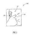
- Fig. 1 is a schematic illustration of system providing input to an earpiece constructed and operative in accordance with the present invention
- Fig.2 is a block diagram illustration of the elements forming the system of Fig. 1 , constructed and operative in accordance with the present invention
- Fig. 3 is an exemplary signal of three knocks that may be recognized by bone conduction microphone constructed and operative in accordance with the present invention
- Fig. 4 is an exemplary lookup table constructed and operative in accordance with the present invention.
- FIG. 5 is a schematic illustration of an alternative embodiment of Fig.1 constructed and operative in accordance with the present invention
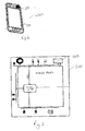
- Fig. 6 is a schematic illustration of a bone conduction microphone embedded in a mobile communication device constructed and operative in accordance with the present invention
- Fig. 7 is a diagram of the hardware ofFig. 6, constructed and operative in accordance with the present invention.
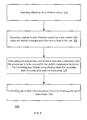
- Fig. 8 is a schematic illustration of a method in accordance with the present invention.
- a mobile communication device that comprises a vibration sensor embedded in a housing of said mobile communication device, said vibration sensor for detecting vibrations; an instruction generator to detect a pattern in said vibrations caused by a user's patterned contact with either said housing or said user's head and to translate said pattern into a set of instructions to said device according to a pre-determined look up table; and an operating system to receive said set of instructions and to control said mobile communication device accordingly.
- the set of instructions may include one or more instructions.
- the vibration sensor may be a bone conduction microphone.
- a method for controlling a mobile communication device may include: detecting with a vibration sensor, vibrations caused by a user's patterned contact with said mobile communication device or said user's head; processing predefined patterns of said vibrations using a predefined lookup table of instructions and determining an associated instruction; and providing the determined instruction to the operating system of said mobile communication device.
- the vibration sensor may be a bone conduction microphone.
- a mobile communication device may include a vibration sensor that is arranged to detect vibrations; an instruction generator that is coupled to the vibration sensor and is arranged to: detect a pattern in said vibrations caused by a user contact with either the mobile communication device or a head of the user, and translate said pattern into a set of instructions that is associated with the pattern and is to be executed by the mobile communication device.
- the mobile communication device may include an operating system that is arranged to receive the set of instructions and to control said mobile communication device accordingly.
- the instruction generator may be arranged to receive or generate a lookup table that associates patterns to sets of at least one instruction.
- the vibration sensor may be a bone conduction microphone.
- the vibration sensor may be embedded within an earpiece.
- the mobile communication device may be a mobile phone and the vibration sensor is embedded within the mobile phone.
- the vibration sensor may be embedded in a front screen panel of the mobile communication device.
- the vibration sensor may be embedded in a backside of the mobile communication device.
- the instruction generator may be arranged to sense the pattern in vibrations induced by a tapping of the user on the head of the user or on the mobile communication device.
- the instruction generator may be arranged to sense the pattern in vibrations induced by a scratching of the user of the head of the user or of the mobile communication device.
- the pattern of a scratching may include a direction of the scratching by the user.
- the instruction generator may be arranged to generate an instruction to lower a first characteristic of an operation of the mobile communication device if detecting a scratching along a first direction and to generate an instruction to decrease the first characteristic of the operation of the mobile communication device if detecting a scratching along a second direction that is substantially opposite to the first direction.
- the instruction generator may be arranged to generate an instruction to lower a second characteristic of an operation of the mobile communication device if detecting a scratching along a thirddirection and to generate an instruction to decrease the second characteristic of the operation of the mobile communication device if detecting a scratching along a fourth direction that is substantially opposite to the third direction and is not-parallel to the first direction.
- the instruction generator may be responsive to at least two parameters out of: a length of a scratching or tapping, a direction of the scratching or tapping and to an intensity of the scratching or tapping.
- the instruction generator may be responsive to a length of a scratching or tapping, a direction of the scratching or tapping and to an intensity of the scratching or tapping.
- the mobile communication device may include a housing that comprises a converter for converting a contact of a user to a series of vibrations.
- the converter may include a selection of pits.
- a method for controlling a mobile communication device may include:detecting vibrations by a vibration sensor; detecting a pattern in said vibrations caused by a user contact with either the mobile communication device or a head of the user; andtranslating said pattern into a set of instructions that is associated with the pattern and is to be executed by the mobile communication device.
- the method may include controlling the mobile communication device by executing the set of instructions.
- a non-transitory computer readable medium that stores instructions for receiving detection signals indicative of vibrations that are sensed by a vibration sensor of a mobile communication device; detecting a pattern in said vibrations caused by a user contact with either the mobile communication device or a head of the user; and translating said pattern into a set of instructions that is associated with the pattern and is to be executed by the mobile communication device.
- Any reference in the specification to a method should be applied mutatis mutandis to a system capable of executing the method and should be applied mutatis mutandis to a non-transitory computer readable medium that stores instructions that once executed by a computer result in the execution of the method.
- Any reference in the specification to a system should be applied mutatis mutandis to a method that may be executed by the system and should be applied mutatis mutandis to a non-transitory computer readable medium that stores instructions that may be executed by the system.
- Any reference in the specification to a non-transitory computer readable medium should be applied mutatis mutandis to a system capable of executing the instructions stored in the non-transitory computer readable medium and should be applied mutatis mutandis to method that may be executed by a computer that reads the instructions stored in the non-transitory computer readable medium.
- Bone conduction is the conduction of sound to the inner ear through the bones of the skull.
- Bone conduction transducers or microphones are known in the art as devices for converting the vibration signal that is picked up from the bone into an analogor digital voice signal. The resultantsignal may be further processed and used accordingly. It will be appreciated that a bone conduction microphone can be embedded in any devicethat directly touches the skullor the head.
- this technology may be useful for controlling mobile phones, headsets and earpieces, such as those described hereinabove, when suitably embedded.
- this technology may also be adapted for any form of headgear that sits in direct contact with the head and where a bone conduction microphone may be embedded.
- any digitally controlled headpiece or earpiece may be used.
- the present discussion presents examples using a Bluctooth earpiece.
- Fig.1 illustrates a system 100 for providing input to an earpiece, such as a typical Bluetooth earpiece 20.
- an earpiece such as a typical Bluetooth earpiece 20.
- user 10 taps the side of his head using his finger 50, he may set off a pattern of pulses which may vibrate throughout his skull.
- user 10 may knock or scratch his head at any location.
- System 100 may comprise bone conduction microphone 30, an analog to digital convertor 35 and an instruction generator 40 and may provide instructions to an operating system 25 of earpiece 20.
- System 100 may provide instructions from a user to a headpiece or an earpiece, such as earpiece 20.
- Bone conduction microphone 30, which may be embedded within earpiece 20 and may touch the head (and therefore the skull) of user 10, may pick up the pulses of the vibration that pass through the skull when user 10 taps his head and may convert them into an analog signal and/or a digital signal. If required, the analog signal may then be digitized by analog to digital convertor 35 with appropriate amplification. The digital signal produced may be furtherreceived and analyzed by instruction generator 40 which may use a lookup table 45 to interpret the desired action according to the pattern of the pulsesin the received signal. Instruction generator 40 may then instruct operating system25 which in turn may instruct earpiece 20 to function according to the required action, such as answering a phone call or playing music.
- instruction generator 40 may also be embedded as part of operating system 25.
- Fig. 3 illustrates an exemplary signal of three knocks that may be recognized by bone conduction microphone 30.
- the knocks are approximately 0.3 seconds apart though this is exemplary.
- System 100 may recognize these knocks and may compare the pattern of knocks with preset patterns assigned to instructions for earpiece 20.
- Fig. 4 illustrates an example of lookup table 45.
- the different functionalities of earpiece 20 may be associated with predefined patterns of pulses.
- table "x" represents a single tap and "-"represents a pause.
- user 10 may tap his head twice quickly, pause and then tap once again.
- the pattern "xx---x" may be assigned to the action "play music”.
- the lockup table may be programmed or otherwise embedded in the mobile communication device.
- the user can build the mapping included in the lookup table or update the lookup table by entering the mobile communication device into a learning mode. This (entering into learning mode) can require pressing a button or may be based upon at least one predefined pattern already known to the mobile communication device.
- mapping is only one example for mapping (or associating) between patterns and instructions. Any other mapping can be used.
- the mapping can be implemented by using a mathematical function.
- instruction generator 40 may still interpret the knocking as a valid command, which may generate a false action.
- the defined patterns need to be unique, i.e. patterns that are not likely to be done by user 10 subconsciously or as part of his daily routine.A solution may be to start each pattern with two taps.It will be further appreciated that if instruction generator 40 does not find a pattern match within a predetermined length of time, it will return a false negative and no function is activated.
- user 10 may use a drawn out contact with his head, such as a scratch,for further functionality.
- the pattern of vibrations created may also be detected by bone conduction microphone 30 and may be analyzed by instruction generator 40 to identify the desired functionality as described hereinabove.
- the signal generated by a scratch may differ from those generated by a tap and may last for a longer length of time.
- Lockup table 45 may be adjusted accordingly to interpret these signals.
- a direction of a scratching can be detected and interpreted as a pattern.
- the sliding action of a scratch may also be interpreted as a volume slider. If the movement of an upward scratch is distinguishable from the movement of a downward scratch, the resulting actions may be used to increase and decrease volume. Volume may be increased or decreased linearly in correlation with the length of time finger 50 is in contact with the head.
- user 10 may also tapearpiece 20 instead of his head to instructit.
- the resultant vibrations may also be detected by bone conduction microphone 30 (typically housed in the earpiece being tapped) and analyzed by instruction generator40to identify the desired command as described hereinabove.
- Fig. 5 illustrates the front panel of a Bluetooth earpiece20 comprising a selection of pits 90.
- user 10 may slide his finger 50 over pits 90.
- the jerky movementof finger 50 over pits 90 may also generate a pattern of vibrations similar to the tapping described hereinabove.
- the resultant vibrations may also be detected by bone conduction microphone 30 and processed as described hereinabove.
- running finger 50 over pits 90 may also be interpreted by lookup table 45 in the same manner as a scratch in order to increase and decrease volume.
- this method of controlling earpiece 20 by "tapping” and “scratching” the head may override the necessity to use the buttons and switches of an earpiece.
- this method of controlusing "tapping” and “scratching” may also be used to control a pertinent device directly (such as a mobile phone) when implemented accordingly, without using any intermediate apparatus such as a Bluetooth earpiece.
- a pertinent device such as a mobile phone
- this method may be implemented on a touch screen mobile communication device, such as an iPhone, commercially available from Apple Inc. or an Android driven smart phone, such as a Samsung Galaxy, commercially available from Samsung Inc.
- a bone conduction microphone may be implemented in such a mobile communication device in a manner similar to that described in US provisional patent application61/605,287filed 01 March2012 , assigned to the common assignee of the present application and incorporated herein by reference.
- Fig. 6 illustrates a standard mobile communication device (such as a mobile phone) 200 with a bone conduction microphone 250 embedded therein.
- bone conduction microphone 250 may be embedded in the phone as part of the front screen panel 210 or behind the panel attached to it or in any location of the phone that has mechanical connection with the panel and capable to sense the vibration generated by the user on the phone.
- bone conduction microphone 250 may be in direct contact with the skull and instructions may be given by tapping the side of the head as described hereinabove.
- embedded bone conduction microphone 250 may also register vibrations caused from tapping the outer housingof mobile communication device 200. Therefore, by simply tapping device 200 according to a pre-defined lookup table, a user may control device 200 without having to locate a correct touch point on the screen or a combination of keys. For example, a mobile phone located in a pocket or bag that may start to ring at an inconvenient time, such as in a meeting, may be tapped to mute it without having to retrieve it, or a phone call may easily answered whilst driving.
- bone conduction microphone 250 may also be embedded in the rear part of device 200. Although this embodiment may limit the ability to control device 200 by tapping etc. the head, device 200 may still be controlled by tapping its outer housing as described hereinabove.
- FIG. 7 illustrates a typical mobile communication device 200 comprising an embedded bone conduction microphone 250 and a processor 275. Any vibrations picked up by bone conduction microphone 250 either by tapping the head or by tapping device 200 may be transmitted to processor 275 via analog or digital connection 220.
- processor 275 may comprise an instruction generator 40 (as described hereinabove) which may, in turn, include a look-up table 45 functionally similar to the lookup table described with respect to Fig. 4 . Processor 275 may then instruct the operating system of device 200 accordingly. It will be appreciated that processor 275 may also be part of the operating system of device 200.
- functionality may not only be restricted to tapping. Scratching the head or a ridged backing on device 200 with pits similar to that as illustrated in Fig.5 may also be used to provide instructions, such as increase/decrease volume etc.
- control device 200 may be used in conjunction with the existing functionality of device 200 to provide even further functionality.
- many advanced mobile communication devices have voice recognition capabilities which may be used to provide instructions orally to device 200.
- user 10 may not use voice recognition mid conversation without significantly pausing the conversation to manually activate the voice recognition mode.
- user 10 may tapdevice200 (or head) accordingly during a conversation in order to activate voice recognition modewithout removing the device 200 from his ear. Once voice recognition mode has been activated, user 10 may use it to increase functionality such as to verbally instruct device 200 to add other callers from his address book to his conversation.
- bone conduction microphones in conjunction with processors may not be limited to such headpieces or devices as described hereinabove.
- Bone conduction microphones due to their small size, may also be embedded in any form of accessory that touches the skull, such as different forms of headgear and spectacles. For example, when teamed up with an appropriate processor, a head torch may be controlled by tapping the head.
- any form of suitable vibration sensor may be used in place of a bone conduction microphone.
- Fig. 8 illustrates method 300 according to an embodiment of the invention.
- Method 300 starts by stage 310 of detecting vibrations by a vibration sensor.
- Stage 310 may be followed by stage 320 of detecting a pattern in said vibrations caused by a user contact with either the mobile communication device or a head of the user.
- the patterns may be cause by having the user tap his head or the mobile communication device, scratch his head or the mobile communication device or perform any movement that will induce vibrations according to a desired pattern.
- the detection of a pattern may include detecting time gaps between vibrations, detecting the number of vibrations induced during a predetermined period of time, detecting the direction of a movement that caused the vibrations, detecting the strength of vibrations and the like.
- the detection of the pattern may include detecting a direction of scratching. Different directions may be translated to different instructions.
- Stage 320 may be followed by stage 330 of translating said pattern into a set of instructions that is associated with the pattern and is to be executed by the mobile communication device.
- the translating may include using a lookup table that associates patterns to sets of at least one instruction.
- the translating may include generating an instruction to lower a first characteristic of an operation of the mobile communication device if detecting a scratching along a first direction and to generating an instruction to decrease the first characteristic of the operation of the mobile communication device if detecting a scratching along a second direction that is substantially opposite (for example within an angular range of between 150 and 210 degrees) of to the first direction.
- the translating may include generating an instruction to lower a second characteristic of an operation of the mobile communication device if detecting a scratching along a third direction and generating an instruction to decrease the second characteristic of the operation of the mobile communication device if detecting a scratching along a fourth direction that is substantially opposite to the third direction and is not-parallel to the first direction (for example- is about 60 to 120 degrees offset).
- the translating may be responsive to at least two parameters out of: a length of a scratching or tapping, a direction of the scratching or tapping and to an intensity of the scratching or tapping.
- Stage 330 may be followed by stage 340 of controlling the mobile communication device by executing the set of instructions.
- the controlling may include changing a characteristic of operation of the mobile communication device (change sound level, change an equalizer setting, change a display of information, skip between media items, answer a phone call, skip between operational mode of operation and the like) or performing ally control operation that may affect the manner in which the mobile communication operates.
- the mobile communication device may include an operating system and stage 340 may include receiving the set of instructions by the operating system and controlling said mobile communication device by the operating system in accordance with the set of instructions.
- Embodiments of the present invention may include apparatus for performing the operations herein.
- This apparatus may be specially constructed for the desired purposes, or it may comprise a general-purpose computer selectively activated or reconfigured by a computer program stored in the computer.
- a computer program may be stored in a computer readable storage medium, such as, but not limited to, any type of disk, including floppy disks, optical disks, magnetic-optical disks, read-only memories (ROMs), compact disc read-only memories (CD-ROMs), random access memories (RAMs), electrically programmable read-only memories (EPROMs), electrically erasable and programmable read only memories (EEPROMs), magnetic or optical cards, Flash memory, or any other type of media suitable for storing electronic instructions and capable of being coupled to a computer system bus.
- ROMs read-only memories
- CD-ROMs compact disc read-only memories
- RAMs random access memories
- EPROMs electrically programmable read-only memories
- EEPROMs electrically erasable and
- connections as discussed herein may be any type of connection suitable to transfer signals from or to the respective nodes, units or devices, for example via intermediate devices. Accordingly, unless implied or stated otherwise, the connections may for example be direct connections or indirect connections.
- the connections may be illustrated or described in reference to being a single connection, a plurality of connections, unidirectional connections, or bidirectional connections. However, different embodiments may vary the implementation of the connections. For example, separate unidirectional connections may be used rather than bidirectional connections and vice versa.
- plurality of connections may be replaced with a single connection that transfers multiple signals serially or in a time multiplexed manner. Likewise, single connections carrying multiple signals may be separated out into various different connections carrying subsets of these signals. Therefore, many options exist for transferring signals.
- Each signal described herein may be designed as positive or negative logic.
- the signal In the case of a negative logic signal, the signal is active low where the logically true state corresponds to a logic level zero.
- the signal In the case of a positive logic signal, the signal is active high where the logically true state corresponds to a logic level one.
- any of the signals described herein may be designed as either negative or positive logic signals. Therefore, in alternate embodiments, those signals described as positive logic signals may be implemented as negative logic signals, and those signals described as negative logic signals may be implemented as positive logic signals.
- assert or “set” and “negate” (or “dessert” or “clear”) are used herein when referring to the rendering of a signal, status bit, or similar apparatus into its logically true or logically false state, respectively. If the logically true state is a logic level one, the logically false state is a logic level zero. And if the logically true state is a logic level zero, the logically false state is a logic level one.
- logic blocks are merely illustrative and that alternative embodiments may merge logic blocks or circuit elements or impose an alternate decomposition of functionality upon various logic blocks or circuit elements.
- architectures depicted herein are merely exemplary, and that in fact many other architectures may be implemented which achieve the same functionality.
- any arrangement of components to achieve the same functionality is effectively “associated” such that the desired functionality is achieved.
- any two components herein combined to achieve a particular functionality may be seen as “associated with” each other such that the desired functionality is achieved, irrespective of architectures or intermedial components.
- any two components so associated can also be viewed as being “operably connected,” or “operably coupled,” to each other to achieve the desired functionality.
- the illustrated examples may be implemented as circuitry located on a single integrated circuit or within a same device.
- the examples may be implemented as any number of separate integrated circuits or separate devices interconnected with each other in a suitable manner.
- the examples, or portions thereof may implemented as soft or code representations of physical circuitry or of logical representations convertible into physical circuitry, such as in a hardware description language of any appropriate type.
- the invention is not limited to physical devices or units implemented in non-programmable hardware but can also be applied in programmable devices or units able to perform the desired device functions by operating in accordance with suitable program code, such as mainframes, minicomputers, servers, workstations, personal computers, notepads, personal digital assistants, electronic games, automotive and other embedded systems, cell phones and various other wireless devices, commonly denoted in this application as 'computer systems'.
- suitable program code such as mainframes, minicomputers, servers, workstations, personal computers, notepads, personal digital assistants, electronic games, automotive and other embedded systems, cell phones and various other wireless devices, commonly denoted in this application as 'computer systems'.
- any reference signs placed between parentheses shall not be construed as limiting the claim.
- the word 'comprising' does not exclude the presence of other elements or steps then those listed in a claim.
- the terms "a” or "an,” as used herein, are defined as one or more than one.
Landscapes
- Engineering & Computer Science (AREA)
- Signal Processing (AREA)
- Physics & Mathematics (AREA)
- Acoustics & Sound (AREA)
- Computer Networks & Wireless Communication (AREA)
- Databases & Information Systems (AREA)
- Telephone Function (AREA)
- Details Of Audible-Bandwidth Transducers (AREA)
- Telephone Set Structure (AREA)
- Percussion Or Vibration Massage (AREA)
Applications Claiming Priority (1)
| Application Number | Priority Date | Filing Date | Title |
|---|---|---|---|
| US201261641916P | 2012-05-03 | 2012-05-03 |
Publications (2)
| Publication Number | Publication Date |
|---|---|
| EP2661105A2 true EP2661105A2 (de) | 2013-11-06 |
| EP2661105A3 EP2661105A3 (de) | 2014-12-17 |
Family
ID=48193190
Family Applications (1)
| Application Number | Title | Priority Date | Filing Date |
|---|---|---|---|
| EP13166387.4A Withdrawn EP2661105A3 (de) | 2012-05-03 | 2013-05-03 | System und Vorrichtung zur Steuerung einer Vorrichtung mit einem Knochenleitwandler |
Country Status (5)
| Country | Link |
|---|---|
| US (1) | US20130303144A1 (de) |
| EP (1) | EP2661105A3 (de) |
| JP (1) | JP2014003592A (de) |
| KR (1) | KR20130124206A (de) |
| CN (1) | CN103425489A (de) |
Families Citing this family (9)
| Publication number | Priority date | Publication date | Assignee | Title |
|---|---|---|---|---|
| CN104317388B (zh) * | 2014-09-15 | 2018-12-14 | 联想(北京)有限公司 | 一种交互方法及穿戴式电子设备 |
| KR101939774B1 (ko) | 2015-07-15 | 2019-01-17 | 삼성전자주식회사 | 웨어러블 디바이스 및 웨어러블 디바이스의 동작 방법. |
| CN105138319B (zh) * | 2015-07-30 | 2018-12-18 | 小米科技有限责任公司 | 事件提醒方法及装置 |
| US20170333754A1 (en) * | 2016-05-17 | 2017-11-23 | Kuaiwear Limited | Multi-sport biometric feedback device, system, and method for adaptive coaching |
| WO2018023418A1 (zh) * | 2016-08-02 | 2018-02-08 | 张阳 | 一种自动播放音乐的方法以及眼镜 |
| WO2018023419A1 (zh) * | 2016-08-02 | 2018-02-08 | 张阳 | 一种音乐播放技术的数据采集方法以及眼镜 |
| WO2018023420A1 (zh) * | 2016-08-02 | 2018-02-08 | 张阳 | 一种自动播放音乐的专利信息推送方法以及眼镜 |
| CN108519871B (zh) | 2018-03-30 | 2020-07-21 | Oppo广东移动通信有限公司 | 音频信号处理方法及相关产品 |
| CN111131606A (zh) * | 2019-12-05 | 2020-05-08 | 维沃移动通信有限公司 | 一种状态控制方法、电子设备 |
Citations (6)
| Publication number | Priority date | Publication date | Assignee | Title |
|---|---|---|---|---|
| DE10145994A1 (de) * | 2001-09-18 | 2003-04-17 | Siemens Audiologische Technik | Steuerung eines Hörgeräts durch Klopfen |
| EP1762926A2 (de) * | 2005-09-09 | 2007-03-14 | Samsung Electronics Co., Ltd. | Verfahren und System zur Steuerung des Betriebs eines Multimediageräts |
| US20080130910A1 (en) * | 2006-11-30 | 2008-06-05 | Motorola, Inc. | Gestural user interface devices and methods for an accessory to a wireless communication device |
| EP1936929A1 (de) * | 2006-12-21 | 2008-06-25 | Samsung Electronics Co., Ltd | Haptisches Erzeugungsverfahren und System für Mobiltelefon |
| WO2009071919A1 (en) * | 2007-12-07 | 2009-06-11 | The University Court Of The University Of Glasgow | Controller |
| US20100110368A1 (en) * | 2008-11-02 | 2010-05-06 | David Chaum | System and apparatus for eyeglass appliance platform |
Family Cites Families (10)
| Publication number | Priority date | Publication date | Assignee | Title |
|---|---|---|---|---|
| JPH1065996A (ja) * | 1996-08-23 | 1998-03-06 | Olympus Optical Co Ltd | 頭部装着型表示装置 |
| US6354299B1 (en) * | 1997-10-27 | 2002-03-12 | Neuropace, Inc. | Implantable device for patient communication |
| US6912287B1 (en) * | 1998-03-18 | 2005-06-28 | Nippon Telegraph And Telephone Corporation | Wearable communication device |
| JP4728537B2 (ja) * | 2001-09-14 | 2011-07-20 | 株式会社ホンダアクセス | ブルートゥース通信システム |
| US20080214160A1 (en) * | 2007-03-01 | 2008-09-04 | Sony Ericsson Mobile Communications Ab | Motion-controlled audio output |
| US8542857B2 (en) * | 2008-03-31 | 2013-09-24 | Cochlear Limited | Bone conduction device with a movement sensor |
| US20090270141A1 (en) * | 2008-04-29 | 2009-10-29 | Sony Ericsson Mobile Communications Ab | Apparatus having input means with rugged surface |
| US8320578B2 (en) * | 2008-04-30 | 2012-11-27 | Dp Technologies, Inc. | Headset |
| US20110003550A1 (en) * | 2009-07-03 | 2011-01-06 | Sony Ericsson Mobile Communications Ab | Tactile input for accessories |
| JP2014515140A (ja) * | 2011-04-01 | 2014-06-26 | イェフダイ、ウリ | 骨伝導振動子を備えるユーザインタフェースを制御するためのシステムおよび装置 |
-
2013
- 2013-04-30 US US13/873,307 patent/US20130303144A1/en not_active Abandoned
- 2013-05-02 JP JP2013096731A patent/JP2014003592A/ja active Pending
- 2013-05-02 KR KR1020130049268A patent/KR20130124206A/ko not_active Withdrawn
- 2013-05-03 EP EP13166387.4A patent/EP2661105A3/de not_active Withdrawn
- 2013-05-03 CN CN2013102955008A patent/CN103425489A/zh active Pending
Patent Citations (6)
| Publication number | Priority date | Publication date | Assignee | Title |
|---|---|---|---|---|
| DE10145994A1 (de) * | 2001-09-18 | 2003-04-17 | Siemens Audiologische Technik | Steuerung eines Hörgeräts durch Klopfen |
| EP1762926A2 (de) * | 2005-09-09 | 2007-03-14 | Samsung Electronics Co., Ltd. | Verfahren und System zur Steuerung des Betriebs eines Multimediageräts |
| US20080130910A1 (en) * | 2006-11-30 | 2008-06-05 | Motorola, Inc. | Gestural user interface devices and methods for an accessory to a wireless communication device |
| EP1936929A1 (de) * | 2006-12-21 | 2008-06-25 | Samsung Electronics Co., Ltd | Haptisches Erzeugungsverfahren und System für Mobiltelefon |
| WO2009071919A1 (en) * | 2007-12-07 | 2009-06-11 | The University Court Of The University Of Glasgow | Controller |
| US20100110368A1 (en) * | 2008-11-02 | 2010-05-06 | David Chaum | System and apparatus for eyeglass appliance platform |
Non-Patent Citations (1)
| Title |
|---|
| CHRIS HARRISON ET AL: "Scratch input: Creating Large, Inexpensive, Unpowered and Mobile Finger Input Surfaces", PROCEEDINGS OF THE 21ST ANNUAL ACM SYMPOSIUM ON USER INTERFACE SOFTWARE AND TECHNOLOGY, UIST '08, 19 October 2008 (2008-10-19), New York, New York, USA, pages 205 - 208, XP055132885, ISBN: 978-1-59-593975-3, DOI: 10.1145/1449715.1449747 * |
Also Published As
| Publication number | Publication date |
|---|---|
| JP2014003592A (ja) | 2014-01-09 |
| EP2661105A3 (de) | 2014-12-17 |
| US20130303144A1 (en) | 2013-11-14 |
| KR20130124206A (ko) | 2013-11-13 |
| CN103425489A (zh) | 2013-12-04 |
Similar Documents
| Publication | Publication Date | Title |
|---|---|---|
| EP2661105A2 (de) | System und Vorrichtung zur Steuerung einer Vorrichtung mit einem Knochenleitwandler | |
| US20140079239A1 (en) | System and apparatus for controlling a user interface with a bone conduction transducer | |
| CN108519871B (zh) | 音频信号处理方法及相关产品 | |
| KR100677613B1 (ko) | 멀티미디어 기기의 동작을 제어하는 방법 및 그 장치 | |
| CN108668009B (zh) | 输入操作控制方法、装置、终端、耳机及可读存储介质 | |
| CN102770829B (zh) | 输入设备、输入方法和程序 | |
| US20090124286A1 (en) | Portable hands-free device with sensor | |
| CN107105367A (zh) | 一种音频信号处理方法及终端 | |
| CN102149039A (zh) | 经由上下文传感器的音频系统的控制 | |
| CN108803859A (zh) | 信息处理方法、装置、终端、耳机及可读存储介质 | |
| CN108710615A (zh) | 翻译方法及相关设备 | |
| CN106791109A (zh) | 一种声音提醒方法及移动终端 | |
| CN108391207A (zh) | 数据处理方法、装置、终端、耳机及可读存储介质 | |
| CN107371102B (zh) | 音频播放音量的控制方法、装置及存储介质和移动终端 | |
| CN106888327B (zh) | 语音播放方法及装置 | |
| CN109618263A (zh) | 头/颈部倾角检测方法、装置、系统及无线耳机控制器 | |
| CN109067965A (zh) | 翻译方法、翻译装置、可穿戴装置及存储介质 | |
| US10582290B2 (en) | Earpiece with tap functionality | |
| CN105554631B (zh) | 音频切换方法、装置及电子设备 | |
| JP6332262B2 (ja) | 情報処理装置、情報処理方法、及び情報処理プログラム | |
| CN105848027A (zh) | 基于声音控制耳机马达振动效果的方法、移动终端及系统 | |
| CN108391208A (zh) | 信号切换方法、装置、终端、耳机及计算机可读存储介质 | |
| CN107450940A (zh) | 智能终端打开应用程序的方法及装置 | |
| KR101153329B1 (ko) | 통신단말기에 있어서 센서에 의한 볼륨조절방법 | |
| CN104754120B (zh) | 一种终端 |
Legal Events
| Date | Code | Title | Description |
|---|---|---|---|
| PUAI | Public reference made under article 153(3) epc to a published international application that has entered the european phase |
Free format text: ORIGINAL CODE: 0009012 |
|
| AK | Designated contracting states |
Kind code of ref document: A2 Designated state(s): AL AT BE BG CH CY CZ DE DK EE ES FI FR GB GR HR HU IE IS IT LI LT LU LV MC MK MT NL NO PL PT RO RS SE SI SK SM TR |
|
| AX | Request for extension of the european patent |
Extension state: BA ME |
|
| PUAL | Search report despatched |
Free format text: ORIGINAL CODE: 0009013 |
|
| AK | Designated contracting states |
Kind code of ref document: A3 Designated state(s): AL AT BE BG CH CY CZ DE DK EE ES FI FR GB GR HR HU IE IS IT LI LT LU LV MC MK MT NL NO PL PT RO RS SE SI SK SM TR |
|
| AX | Request for extension of the european patent |
Extension state: BA ME |
|
| RIC1 | Information provided on ipc code assigned before grant |
Ipc: H04R 25/00 20060101AFI20141112BHEP Ipc: H04R 1/10 20060101ALI20141112BHEP |
|
| 17P | Request for examination filed |
Effective date: 20150617 |
|
| RBV | Designated contracting states (corrected) |
Designated state(s): AL AT BE BG CH CY CZ DE DK EE ES FI FR GB GR HR HU IE IS IT LI LT LU LV MC MK MT NL NO PL PT RO RS SE SI SK SM TR |
|
| 17Q | First examination report despatched |
Effective date: 20150814 |
|
| STAA | Information on the status of an ep patent application or granted ep patent |
Free format text: STATUS: THE APPLICATION IS DEEMED TO BE WITHDRAWN |
|
| 18D | Application deemed to be withdrawn |
Effective date: 20160812 |