EP2661966B1 - Dispositif de traitement d'un chapelet de saucisses - Google Patents
Dispositif de traitement d'un chapelet de saucisses Download PDFInfo
- Publication number
- EP2661966B1 EP2661966B1 EP13164217.5A EP13164217A EP2661966B1 EP 2661966 B1 EP2661966 B1 EP 2661966B1 EP 13164217 A EP13164217 A EP 13164217A EP 2661966 B1 EP2661966 B1 EP 2661966B1
- Authority
- EP
- European Patent Office
- Prior art keywords
- microwave
- applicator
- sausages
- radiation
- microwave applicator
- Prior art date
- Legal status (The legal status is an assumption and is not a legal conclusion. Google has not performed a legal analysis and makes no representation as to the accuracy of the status listed.)
- Active
Links
Images


Classifications
-
- A—HUMAN NECESSITIES
- A22—BUTCHERING; MEAT TREATMENT; PROCESSING POULTRY OR FISH
- A22C—PROCESSING MEAT, POULTRY, OR FISH
- A22C11/00—Sausage making ; Apparatus for handling or conveying sausage products during manufacture
- A22C11/10—Apparatus for twisting or linking sausages
-
- H—ELECTRICITY
- H05—ELECTRIC TECHNIQUES NOT OTHERWISE PROVIDED FOR
- H05B—ELECTRIC HEATING; ELECTRIC LIGHT SOURCES NOT OTHERWISE PROVIDED FOR; CIRCUIT ARRANGEMENTS FOR ELECTRIC LIGHT SOURCES, IN GENERAL
- H05B6/00—Heating by electric, magnetic or electromagnetic fields
- H05B6/64—Heating using microwaves
- H05B6/78—Arrangements for continuous movement of material
- H05B6/782—Arrangements for continuous movement of material wherein the material moved is food
Definitions
- the invention relates to a device for treating a sausage strand consisting of a plurality of sausages arranged one behind another with a sausage casing made of an organic material which has a Abwindung in the area between two sausages.
- the sausage meat is usually pressed by means of a filling machine through a filling tube into a tubular sausage casing.
- a twisting mechanism By means of a twisting mechanism, the individual sausage portions, ie the individual sausages themselves, formed by the sausage strand is rotated so that the strand constricts locally and to form a twisting of the sausage casing (see. EP 2 332 416 A2 ).
- the individual sausages are thus separated from each other via such a shell-side twisting.
- the sausage strand formed in this way is then separated by means of a separating device.
- the sausage strand is gripped by two conveyor belts, which transport the sausage strand at a defined speed to a cutting device, where the individual sausages are separated in the region of the twisting.
- the separation is usually carried out by means of two counter-rotating or rotating knives, which interact on average, wherein one of the blades can also be designed as a pure counter-holder.
- the invention is based on the problem to provide a device for treating a sausage strand, which allows a treatment of the sausage strand so that in a simple way allows separation of the sausages. the use of a downstream cutting device can be dispensed with.
- the device according to the invention it is possible to thermally treat the sausage strand by application of microwave radiation, ie to supply energy which leads to a heating of the treated material.
- the microwave radiation can be applied only in the region of the Abwindungen by appropriate control of the microwave generating devices, ie, that the radiation is generated clocked, what about a suitable detection device (sensor) is detected when a twist in the Application is one of the at least two intended applicators.
- the microwave radiation is supplied continuously, ie, that the entire sausage strand, so sausages and Abwindungen, are acted upon by the microwave radiation.
- the device according to the invention is characterized by at least two in the transport respectively strand longitudinal direction successively arranged microwave applicators.
- Each microwave applicator is associated with at least one dedicated microwave generating device, i. That is, each applicator is fed separately with generated microwave radiation.
- each microwave applicator is associated with a separate transport device, which transports the sausage strand through the applicator for acting on the generated microwave radiation.
- These transport devices are arranged one behind the other in the conveying direction, d. That is, that the sausage strand is detected by the one transport device, transported by the first applicator, transferred to the second transport device and conveyed by the same through the second microwave applicator.
- the generated microwave radiation is supplied to the respective microwave applicator.
- the respective transport device transports the sausage strand through the respective microwave applicator, where the sausage strand is then exposed to the microwave radiation in a defined application region.
- an energy input occurs, which leads to a material warming.
- the covering material is either a natural, organic material, namely an animal intestine, or an artificial intestine, ie also an organic plastic material, as a result of the energy input and the resulting heating, the material or material structure changes , It sets in the case of Naturdarms a coagulation process, ie that proteins or proteins change their structure and coagulate. This process starts at a temperature of usually more than 40 ° C.
- the application of the microwave radiation also to the sausage itself also leads to a slight coagulation-related or crosslinking-related material change of the sausage casing and thus to a certain stiffening, but not comparable to the extreme embrittlement to breakage in the field of Abwindungen. Because in the sausage area, the injected thermal energy is dissipated via the cold sausage meat or the sausage mass, so that, based on the sausage casing itself, the local energy input is significantly lower.
- the slight embrittlement of the sausage casing in the sausage area is even an advantage, as the sausages thereby overall something stiffen and therefore their elongated, straight shape, which they have in consequence of the promotion on the transport devices consisting of the two conveyor belts, ultimately also after treatment largely retained, which for the subsequent processing of the sausages, for example, in the context of further promotion or packaging or the like is beneficial.
- the decisive factor is that, as stated, there is sufficient energy input in the area of the twists to be cut, so that they embrittle to such an extent that breakage and thus automatic sausage separation occur.
- two separate, downstream microwave applicators are provided in the device according to the invention, each of which is associated with a separate radiation generating device.
- These two microwave radiation generating devices as well as the associated transport devices comprising the superimposed conveyor belts are separately controllable according to the invention, ie that they are individually controllable in their operation.
- the power of the microwave radiation generated is arbitrary and adjustable as needed. This means that the radiant power of the two radiation generating devices can be the same, but it can also be different.
- the second microwave generating device can be slightly readjusted so that the microwave radiation generated there is raised in its power or energy content, so that consequently at the second radiation application site, ie in the second microwave applicator, higher energy radiation is applied, and consequently the twisting something stronger heated and ensured that it comes to complete separation. It is also conceivable, of course, a corresponding increase in the power of the first microwave generating device, or both.
- the first transport device transports the sausage strand somewhat slower than the downstream second transport device, so that in the region of transfer of the sausage strand from the first to the second transport device as a result of the given speed difference to a slight elongation respectively train on the sausage strand.
- the already partially embrittled or hardened twists are consequently subjected to tension, and therefore are lengthened, which can already lead to the twisting breakage.
- this tensile stress then ensures that breaks in the second radiation treatment in the second microwave applicator each Abwindung.
- the invention provided individual controllability of at least two microwave generating devices and the at least two transport devices allows a highly flexible control of the treatment process, so that it is ensured that at the output of the device really all sausages are isolated, without this even a single manual Cutting process using a cutter required. Because the separation takes place according to the invention exclusively by the radiation treatment in the microwave applicators, which allows a high, concentrated radiation input, so that it comes to the extreme embrittlement. This high energy input is also readily possible if the sausage strand is conveyed through the applicators at high speed by means of the transport devices, wherein depending on the sausage length several hundred sausages per minute can be conveyed through and separated.
- each twisting is "completely welded", d. h., That the separate twisting coagulation or crosslinking is closed and does not work.
- This welding is of particular advantage for the subsequent treatment, be it the removal or packing, be it for example a subsequent brewing of the sausages and the like, since an exit of the sausage meat from one end is prevented after a complete sausage closure is given.
- each microwave applicator according to the invention has at least one chamber through which the respective transport device runs and the sausage strand is transported, to which chamber the microwave radiation can be supplied.
- the radiation is thus concentrated in a very small chamber so as to be bundled as possible fed to the transported past sausages and in particular the Abcard.
- a microwave applicator a single-mode applicator is preferably provided, which causes the applicator to form a standing wave, which is discretely distributed in the chamber.
- Applicator geometry and wavelength are coordinated.
- the wavelength is preferably between 5 and 20 cm, in particular between 10 and 15 cm and preferably between 11 and 13 cm, whereby a specific embodiment prefers a wavelength of 12.4 cm.
- the power of the individual microwave generating devices should be 1 - 50 kW, preferably 3 - 30 kW.
- At least one microwave applicator preferably at both applicators, at least two chambers arranged one behind the other are provided, through which the respective transport device runs, and to which either the microwave radiation generated by a microwave generating device can be fed simultaneously, or each associated with its own microwave generating device is.
- two or more chambers arranged one behind the other that is to say cascaded, are provided in each microwave applicator and serve for the radiation treatment.
- a concentrated, focused radiation application is made.
- the supplied radiation is generated either by an applicator own, so common to all chambers provided radiation generating device. It is also conceivable, however, to assign each chamber its own generation device.
- the plurality of radiation generating devices which are assigned to an applicator, either jointly, so synchronously controlled, but as well as an individual controllability is given here, of course. If the radiation generating devices can only be actuated synchronously together, then a power variation between the radiation generating devices and the first applicator relative to those of the second applicator is possible. If, however, the radiation generating devices of an applicator can be controlled individually, then a power variation over all four generating devices is possible, so that consequently a completely individual power profile along the transport path can be set.
- each chamber of an applicator is geometrically designed to be as small and concentrated as possible in order to focus or focus the radiation, but the applicator is a larger-volume component in which the one or more chambers are provided as separate volumes, sees an expedient development of the invention one the respective microwave applicator passing through and through the one or more chambers running, the conveyor belts and the sausage strand receiving conveyor section before.
- This elongated conveyor line thus serves the band and thus the strand guide to and from the chamber or chambers, which can then be designed optimized according to their geometry.
- a particularly advantageous development provides that the two microwave applicators can be opened over their length or locally.
- This makes it possible for the conveyor belts (such a conveyor belt can be both a circulating, fabric-like band, as well as a band consisting of a plurality of individual articulated links) to be easily located in the applicators, respectively, when needed for cleaning purposes , For this purpose, it is only necessary to open the respective applicator, so that the conveyor belts, which run with one strand through the applicator, used or can be removed.
- a portion of the microwave applicator is either pivotally or linearly movably disposed relative to another portion of the applicator or fixture frame.
- this is a microwave applicator of two housing halves, wherein the first half of the housing is fixed in position and the second housing half is either pivotally mounted on the first housing half or on a device frame, or is mounted on the first housing half or the device frame via linear guide elements.
- Each applicator is thus divided along its length so that it can be fully opened and closed.
- the movement of the second housing half, in particular for linear displacement via the linear guide elements, is expediently effected by means of a servomotor, for example a servomotor.
- a position sensor is expediently provided, which ultimately monitors the closed state and which allows the subsequent operation only when the complete closure is sensed, ie, that the operation of the device consequently This sensor detection is controllable. Because only if each applicator is completely closed is it possible to perform a required radiation treatment.
- each housing half consists of a solid material, wherein in at least one half of the housing, a conveying path and a recess forming a chamber is introduced.
- the housing halves are thus solid material components, preferably made of stainless steel or aluminum, therefore made of metal, which brings a very simple cleanability with it.
- the corresponding recesses, which are provided on at least one housing half and form the conveying path respectively at least one of the chambers, can be introduced into this solid material part by milling or the like.
- this Ausappelungsgeomtrie can be introduced only in one half of the housing, while the other half of the housing is quasi planar and serves only for closing the recesses introduced at the other part. It is also conceivable, however, to introduce a "half" recess into each housing half, so that the recess halves complement each other in the closed state to the conveying path or chamber.
- each microwave applicator can be preceded by a sensor for detecting the inlet and outlet of a sausage strand, wherein the operation of the microwave applicator associated with at least one microwave generating device can be controlled as a function of the sensor detection.
- the respective sensor thus detects the strand beginning and the strand end, with the respective radiation generation being switched on only when a sausage strand actually enters and the radiation generation is required. If the strand end is detected, the respective radiation generation switches off. This means that the on-off operation of the microwave generating devices (magnetron) is consequently controlled via this sensor signal.
- the second microwave applicator may be preceded by a sensor by means of which the presence of a twist between two sausages already treated in the first microwave applicator is detectable, the operation of the at least one microwave generating device and / or its associated transport device being controlled by the second microwave applicator being controllable in dependence on the sensor detection ,
- a sensor by means of which the presence of a twist between two sausages already treated in the first microwave applicator is detectable, the operation of the at least one microwave generating device and / or its associated transport device being controlled by the second microwave applicator being controllable in dependence on the sensor detection ,
- the sensor whereupon, for example the radiation power of the second microwave generating device (s) is briefly increased to bring in the second radiation treatment even more energy and bring about the complete embrittlement and breakage, and / or the transport speed of the second transport device are slightly increased to the tensile stress within the already partially to increase the brittleness, or possibly to bring about the break again.
- each applicator is assigned its own transport device comprising two conveyor belts arranged one above the other.
- These guided over rollers conveyor belts according to the invention run with a strand through the respective microwave applicator, with the other strand they are on the outside around the applicator.
- at least a part of the rollers may be positionally adjustable in order to vary the distance between the two debris passing through the microwave applicator and thus to adjust the band gap to adapt to a changing sausage caliber. It is also conceivable to make this change in position by exchanging the conveyor belts, which are then of different thicknesses. If thicker conveyor belts are used, the band gap inevitably decreases in comparison with thinner belts, and vice versa.
- microwave transparent material As conveyor belts, for example, coated fabric tapes or modified Plastic link belts or the like are used, but they are in any case of a microwave transparent material.
- radiation-transparent means that the material has an extremely low absorption of radiation, which lies in a quasi negligible order of magnitude.
- a strip material for example, polytetrafluoroethylene (PTFE), polypropylene (PP), polyethylene (PE) or a silicone may be used.
- Fig. 1 shows a device 1 according to the invention for treating a sausage strand, comprising a device frame 2, not shown here in detail, and two successively arranged with respect to the strand transport direction Microwave applicators 3, 4 each having an associated transport device 5, 6 each comprising two conveyor belts 7, 8 and 9, 10, by means of which a sausage strand through the two Mikrowellenapplikatoren 3, 4 can be promoted.
- the sausage strand is transferred from the transport device 5 to the transport device 6 in the region of the central interface.
- the sausage skein transported therethrough is treated with microwave radiation which is transmitted via in Fig. 1 Microwave generator (magnetron), not shown, is generated.
- Each applicator 3, 4 is associated with at least one microwave generating device, which will be discussed below.
- the operating device 11 the operation of the device 1 is centrally controlled, the control is carried out by means of a central control device 12, see Fig. 2 in which a schematic representation of the control networking is shown.
- the two transport devices 5, 6 are shown with the respective conveyor belts 7 - 10, wherein each conveyor belt 7 - 10, a drive motor 13, 14, 15, 16 is assigned, via which a drive roller 17, 18, 19, 20 is driven, while the band is guided over further pulleys 21.
- the control device 12 communicates with each drive motor 13-16 (preferably synchronous motors) so that it can be controlled individually.
- the configuration is such that the two drive motors 13, 14 are controlled synchronously, as well as the two drive motors 15, 16, so that an absolutely identical synchronous running is given. Because the conveyor belts 7 and 8 should run at the same speed, as well as the two conveyor belts 9, 10.
- the control is such that the two conveyor belts 9, 10 usually run slightly faster than the two conveyor belts 7, 8, so that in the area the interface, so the transfer of the transport device 5 to the transport device 6, an elongation and thus a train within the respective twisting of the sausage strand results, which is conducive to the separation of the respective Abwindung.
- the basic speeds as well as the speed difference can be set individually and as required as a result of the separate adjustment of the respective transport speeds of the transport devices 5 and 6.
- microwave generating devices 22, 23, 24, 25 which are likewise controlled via the control device 12.
- four such devices are provided, wherein the two radiation generating means 22, 23 the applicator 3 and the two radiation generating means 24, 25 associated with the applicator 4 and each feed a chamber with radiation, which will be discussed below.
- microwave generating devices either in pairs, ie the microwave generating devices 22 and 23 synchronously, but individually and different from the synchronously driven generators 24, 25, or each generating device 22 - 25 completely separate and individually operate.
- This offers the possibility of generating a variation between the applicable radiation power in the applicator 3 and the power applied in the applicator 4 within the generated radiation power.
- the radiation power in the applicator 3 can be higher than in the applicator 4, or vice versa, it can also be designed the same as needed.
- the controller 12 controls the operation of the microwave generating means 22-25 such that upon detection of the entry of a new strand, the radiation generating operation begins, so each respective magnetron are turned on, and upon detection of a After the entire strand of the radiation generating operation is turned off. The same can also be done, at least as regards switching off with respect to the drive of the transport devices 5, 6.
- Fig. 3 shows in an enlarged view the two microwave applicators 3, 4 and the associated transport means 5, 6 in the form of the bands 7, 8 and 9, 10, wherein the bands are either coated fabric tapes or link belts or the like, but in any case of a material which is radiolucent exist. Shown are, as far as possible, the drive rollers 17, 18 and 19, as well as partly the pulleys 21, over which the conveyor belts are guided.
- the pulleys 21 are disposed on respective levers 28, which can be pivoted to adjust in this way the tension of the individual conveyor belts 7-10, as may be one of these levers 28 spring-loaded, so that it continuously maintains a certain belt tension.
- the conveyor belts each have a flat inner surface 29, at their acting on the individual sausages 30 of the sausage strand 31 shown here outer side 32, they are the sausage shape slightly adapted, made round, to guide the sausages defined. As Fig. 3 shows, two consecutive sausages are connected to each other via a twisting 33, which applies to separate in the device 1.
- Each microwave applicator 3, 4 is, see the Fig. 3 and 4 ,
- the respective housing halves 34, 36 are fixed to the frame, ie immovable, while the front housing halves 35, 37 are movable in order to open the respective applicator 3, 4.
- these housing halves 35, 37 via two linear guides 38, 39 and 40, 41 are linearly displaceable, so they can via a servomotor not shown here in detail between the in Fig. 3 shown closing position and the in Fig. 4 moved open position shown. This makes it possible to get into the interior of each applicator to clean this or to replace conveyor belts, etc.
- the linear guides 38 - 41 are realized via corresponding rods, which the device frame in pass through respective guides respectively there are stored in corresponding guide bushes and the like.
- the housing halves 34 - 37 corresponding engagement contours 42, 43 and 44, 45 in the form of peripheral edge grooves respectively projections on which engage in the collision.
- a position sensor not shown here in detail, which can also be arranged in the region of the respective linear guides, a correct closing is detected.
- each microwave applicator 3 shows, each microwave applicator 3, 4, two separate chambers 46, 47 and 48, 49, respectively, to which microwave radiation is supplied.
- This microwave radiation can be generated via a respective chamber's own microwave generating device, so a separate magnetron, so why, see Fig. 2 in which there described embodiment also four such generating devices 22 - 25 are provided.
- the magnetron 22 would thus generate the radiation for the chamber 46, the magnetron 23, the radiation for the chamber 47, the magnetron 24, the radiation for the chamber 48 and the magnetron 25, the radiation for the chamber 49.
- each chamber pair 46/47 or 48/49 with radiation via a common radiation generating device. Since, as described, the radiation generating devices 22, 23 synchronously or individually as well as the radiation generating means 24, 25 synchronously or individually in their producible radiant power via the controller 12 are adjustable, it is therefore possible via the four cascaded here shown four consecutively arranged chambers 46 - 49 quasi to set any radiation power profile. Preferably, the operation is such that the two radiation generating devices 22, 23 generate an equal radiant power, as well as the two radiation generating devices 24, 25, which, however, may be different from the power of the other two devices.
- the chambers 46 - 49 are recesses in the housing halves 34, 36 (which are preferably made of stainless steel or aluminum, ie metal), while the other housing halves 35, 37 are flat. Furthermore, in order to be able to guide the conveyor belts through the chambers 46-49, a horizontal, longitudinal conveyor line 50, 51 is realized on each housing half 34, 36, through which each conveyor belt 7-10 with a respective run 52, 53 or 54, 55 running. D. h., Each conveyor line 50, 51 thus receives the two debris as well as the promoted sausage strand 31. The conveyor lines 50, 51 thus extend through the chambers 46-49, so that the sausage strand is passed through the chambers.
- the sausage strand is treated with the microwave radiation generated by the magnetrons 22-25. This is after the sausage strand has a shell of an organic material, coagulation or crosslinking processes in the shell material and in particular in the Abrehungen 33, which embrittle in this case, since the energy input and thus the warming is strongest, since a removal respectively a dissipation in the Wurstbiller in the field of Abcard 33 just is not possible.
- the radiation input or the heating thus embrittlement sets in, which ensures at least after treatment in the last chamber 49 that each twist 33 is broken, thus leaving the individual sausages 30 the applicator 4 isolated.
- the two transport devices 5, 6 we run running at different speeds, the transport device 6 runs a little faster, so that in the transfer points from the transport device 5 to the transport device 6, a slight train within the individual twisting 33 results, in conjunction with the embrittlement the complete separation is obtained.
- the result is the individual controllability of the radiation generating devices 22-25 respectively of the respective pairs 22/23 or 24/25 the possibility to readjust directly here to be able to.
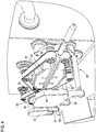
- FIG. 6 Finally, a sectional view through the device 1 from Fig. 1 Here in the area of the applicator 3, which is shown here open, that is, via the two linear guides 38, 39 in conjunction with the servomotor 56 shown here, the housing half 35 which clearly has no recesses, but only the respective chambers respectively conveyor lines forming recesses closes, has moved to the open position.
- the radiation generated is guided to the microwave applicator 3 and coupled there via a corresponding, possibly geometrically adapted to the chamber shape adapter piece 58 with the back of the housing half 34.
- the housing half 34 is naturally open in the region of the chambers 46, 47 (the same naturally applies to the housings 36 of the other applicator), so that the supplied radiation can enter the chamber.
- the adapter piece 58 is then correspondingly designed to guide the radiation to both respective chambers.
Landscapes
- Life Sciences & Earth Sciences (AREA)
- Engineering & Computer Science (AREA)
- Wood Science & Technology (AREA)
- Zoology (AREA)
- Food Science & Technology (AREA)
- Physics & Mathematics (AREA)
- Electromagnetism (AREA)
- Processing Of Meat And Fish (AREA)
- Meat, Egg Or Seafood Products (AREA)
Claims (14)
- Ensemble pour traiter une chaîne de saucisses constituée de plusieurs saucisses disposées les unes derrière les autres et dotées d'une enveloppe de saucisse en matériau organique qui présente une torsion entre deux saucisses,
au moins deux applicateurs (3, 4) de microondes à chacun desquels est associé au moins un dispositif (22, 23, 24, 25) de production de microondes étant prévus pour former un rayonnement de microondes amené aux applicateurs (3, 4) de microondes,
la puissance des rayonnements de microondes formés par les dispositifs (22, 23, 24, 25) de formation de microondes pouvant être commandée séparément, caractérisé en ce que
un dispositif de transport (5, 6) qui comprend deux bandes transporteuses (7, 8, 9, 10) circulant l'une au-dessus de l'autre en boucle fermée pour transporter la chaîne (31) de saucisses à travers les applicateurs (3, 4) de microondes est associé à chacun des applicateurs (3, 4) de microondes,
en ce que les applicateurs (3, 4) de microondes avec leurs dispositifs de transport (5, 6) associés sont disposés l'un derrière l'autre et
en ce que la vitesse de transport de chacun des dispositifs de transport (5, 6) peut également être commandée séparément pour chacun d'entre eux. - Ensemble selon la revendication 1, caractérisé en ce que chaque applicateur (3, 4) de microondes présente au moins une chambre (46, 47, 48, 49) dans laquelle se déplace le dispositif de transport (5, 6) et dans laquelle la chaîne (31) de saucisses est transportée, le rayonnement de microondes pouvant être amené à ces chambres (46, 47, 48, 49).
- Ensemble selon la revendication 2, caractérisé en ce qu'au moins deux chambres (46, 47, 48, 49) sont prévues l'une à la suite de l'autre sur au moins un applicateur (3, 4) de microondes et sont traversées par un dispositif de transport associé (5, 6), en ce que le rayonnement de microondes formé au moyen d'un dispositif (22, 23, 24, 25) de production de microondes peut être amené simultanément à ces chambres ou en ce qu'un dispositif propre (22, 23, 24, 25) de formation de microondes est associé à chacune de ces chambres.
- Ensemble selon les revendications 2 ou 3, caractérisé en ce qu'il présente un parcours de transport (50, 51) qui traverse l'applicateur (3, 4) de microondes, qui s'étend dans la ou les chambres (46, 47, 48, 49) et qui reprend les bandes transporteuses (7, 8, 9, 10) et la chaîne (31) de saucisses.
- Ensemble selon l'une des revendications précédentes, caractérisé en ce que les deux applicateurs (3, 4) de microondes peuvent être ouverts sur toute leur longueur ou localement.
- Ensemble selon la revendication 5, caractérisé en ce qu'une partie de l'applicateur (3, 4) de microondes peut pivoter ou être déplacée linéairement.
- Ensemble selon la revendication 6, caractérisé en ce qu'un applicateur (3, 4) de microondes est constitué de deux moitiés de boîtier (34, 35, 36, 37), la première moitié (34, 36) de boîtier étant immobile et la deuxième moitié (35, 37) de boîtier étant montée à pivotement sur la première moitié (34, 36) de boîtier ou sur un bâti (2) du dispositif, ou est montée par l'intermédiaire d'éléments (38, 39, 40, 41) de guidage linéaire sur la première moitié (34, 36) de boîtier ou sur le bâti (2) de l'ensemble.
- Ensemble selon la revendication 7, caractérisé en ce qu'un moteur pas à pas (56) est prévu pour déplacer les deuxièmes moitiés de boîtier (35, 37) et en particulier pour les déplacer par l'intermédiaire des éléments (38, 39, 40, 41) de guidage linéaire.
- Ensemble selon l'une des revendications 5 à 8, caractérisé en ce qu'au moins un capteur qui saisit l'état de fermeture est associé à chaque applicateur (3, 4) de microondes, le fonctionnement de l'ensemble (1) pouvant être commandé en fonction de la détection par le ou les capteurs.
- Ensemble selon l'une des revendications 7 à 9, caractérisé en ce que chaque moitié de boîtier (34, 35, 36, 37) est constitué d'un matériau plein, une découpe qui forme le parcours de transport (50, 51) et une autre qui forme une chambre (46, 47, 48, 49) étant ménagée dans au moins une moitié (34, 36) du boîtier.
- Ensemble selon l'une des revendications précédentes, caractérisé en ce qu'un capteur (26, 27) de détection de l'entrée et de la sortie d'une chaîne (31) de saucisses est raccordé en amont de chaque applicateur (3, 4) de microondes, le fonctionnement du ou des dispositifs (22, 23, 24, 25) de formation de microondes associés à l'applicateur (3, 4) de microondes pouvant être commandé en fonction de la détection par le capteur.
- Ensemble selon l'une des revendications précédentes, caractérisé en ce qu'un capteur (27) au moyen duquel la présence d'une torsion (33) entre deux saucisses qui ont déjà été traitées dans le premier applicateur (3) de microondes peut être détectée est raccordé en amont du deuxième applicateur (4) de microondes, le fonctionnement du ou des dispositifs (24, 25) de formation de microondes associés au deuxième applicateur (4) de microondes et/ou du dispositif de transport (6) pouvant être commandé en fonction de la détection par le capteur.
- Ensemble selon l'une des revendications précédentes, caractérisé en ce que les bandes transporteuses (7, 8, 9, 10) guidées sur des rouleaux (17, 18, 19, 20, 21) se déplacent par un bras (52, 53, 54, 55) à travers les applicateurs (3, 4) de microondes concernés, l'autre bras étant guidé du côté extérieur autour de l'applicateur (3, 4) de microondes.
- Ensemble selon la revendication 13, caractérisé en ce que la position d'au moins une partie de rouleau (17, 18, 19, 20, 21) peut être ajustée pour modifier la distance entre les deux bras (52, 53, 54, 55) qui traversent l'applicateur (3, 4) de microondes.
Priority Applications (1)
| Application Number | Priority Date | Filing Date | Title |
|---|---|---|---|
| SI201330540A SI2661966T1 (sl) | 2012-05-09 | 2013-04-18 | Naprava za obdelavo niza klobas |
Applications Claiming Priority (1)
| Application Number | Priority Date | Filing Date | Title |
|---|---|---|---|
| DE201210009077 DE102012009077B3 (de) | 2012-05-09 | 2012-05-09 | Vorrichtung zum Behandeln eines Wurststrangs |
Publications (2)
| Publication Number | Publication Date |
|---|---|
| EP2661966A1 EP2661966A1 (fr) | 2013-11-13 |
| EP2661966B1 true EP2661966B1 (fr) | 2016-12-28 |
Family
ID=48184051
Family Applications (1)
| Application Number | Title | Priority Date | Filing Date |
|---|---|---|---|
| EP13164217.5A Active EP2661966B1 (fr) | 2012-05-09 | 2013-04-18 | Dispositif de traitement d'un chapelet de saucisses |
Country Status (3)
| Country | Link |
|---|---|
| EP (1) | EP2661966B1 (fr) |
| DE (1) | DE102012009077B3 (fr) |
| SI (1) | SI2661966T1 (fr) |
Family Cites Families (6)
| Publication number | Priority date | Publication date | Assignee | Title |
|---|---|---|---|---|
| SE439874B (sv) * | 1981-09-23 | 1985-07-08 | Nestle Sa | Sett och anordning for framstellning av kottprodukter |
| US4441003A (en) * | 1982-04-16 | 1984-04-03 | Raytheon Company | Conveyorized microwave oven with multiple lanes |
| JP3571406B2 (ja) * | 1995-03-22 | 2004-09-29 | ハイテック株式会社 | ソーセージ等の製造装置 |
| DE102009058081A1 (de) * | 2009-12-14 | 2012-05-24 | Howe Wurstwaren Kg | Behandlungsvorrichtung für einen Wurststrang |
| DE102010002827A1 (de) * | 2010-03-12 | 2011-09-15 | Albert Handtmann Maschinenfabrik Gmbh & Co. Kg | Vorrichtung und Verfahren zum Trennen von Wurstketten |
| WO2011143452A2 (fr) * | 2010-05-12 | 2011-11-17 | John Novak | Procédé et appareil pour une conception de micro-ondes à double applicateur |
-
2012
- 2012-05-09 DE DE201210009077 patent/DE102012009077B3/de active Active
-
2013
- 2013-04-18 EP EP13164217.5A patent/EP2661966B1/fr active Active
- 2013-04-18 SI SI201330540A patent/SI2661966T1/sl unknown
Non-Patent Citations (1)
| Title |
|---|
| None * |
Also Published As
| Publication number | Publication date |
|---|---|
| EP2661966A1 (fr) | 2013-11-13 |
| SI2661966T1 (sl) | 2017-03-31 |
| DE102012009077B3 (de) | 2013-08-08 |
Similar Documents
| Publication | Publication Date | Title |
|---|---|---|
| EP3215333B1 (fr) | Granulateur à rouleaux pinceurs, installation de granulation comprenant celui-ci et utilisation du granulateur à rouleaux pinceurs | |
| EP1839822B1 (fr) | Dispositif de coupe destiné à la coupe de matériaux en bandes, en particulier de bandes de textile ou de corde en acier | |
| DE112010004275B4 (de) | Verfahren und Vorrichtung zum Formpressen von thermoplastischen Materialien mit hoher Geschwindigkeit und niedrigem Pressdruck | |
| EP2364596B1 (fr) | Dispositif et procédé destinés à la séparation de chaînes de saucisses | |
| DE202012004523U1 (de) | Vorrichtung zum Behandeln eines Wurststrangs | |
| EP2641483A1 (fr) | Dispositif de formatage d'une machine de fabrication de tiges | |
| EP2661966B1 (fr) | Dispositif de traitement d'un chapelet de saucisses | |
| DE102009058080B4 (de) | Vorrichtung zum Vereinzeln von über Abdrehungen miteinander verbundenen Würsten eines Wurststrangs | |
| EP2274986A2 (fr) | Procédé et dispositif de fabrication de petites saucisses | |
| EP2332416A2 (fr) | Dispositif de traitement pour un chapelet de saucisses | |
| EP2873323B1 (fr) | Dispositif de traitement d'un chapelet de saucisses | |
| EP1798020A2 (fr) | Dispositif d'épissage | |
| EP2452564B1 (fr) | Dispositif et méthode de traitement d'un chapelet de saucisses | |
| DE602004007548T2 (de) | Verfahren zur phasenweisen trennung eines wurststrangs, trennelement und anordnung zum trennen von elementen | |
| EP3508066B1 (fr) | Agencement et procédé pour le traitement de volailles | |
| EP1426294B1 (fr) | Procédé et appareil pour emballer des articles plats | |
| DE60300235T2 (de) | Maschine zur Konditionierung von Zigarren | |
| DE69529628T2 (de) | Vorrichtung zum Verpacken von Gegenständen | |
| EP3732978B1 (fr) | Procédé et dispositif de séparation des saucisses d'un chapelet de saucisses | |
| EP2449895A2 (fr) | Dispositif de fabrication de filtres coaxiales pour des articles à fumer en forme de tiges | |
| EP2742805B1 (fr) | Procédé et dispositif de séparation d'un chapelet de saucisses créé par une machine de remplissage | |
| DE102012207538A1 (de) | Verfahren und Vorrichtung zum Anheften von Schrumpfhülsen auf Behältern | |
| EP1781109B1 (fr) | Dispositif pour produire des corps creux en forme de coussins qui sont de preference fourres | |
| WO2012095069A2 (fr) | Produit alimentaire et dispositif et procédé pour sa fabrication | |
| DE7334973U (de) | Vorrichtung zur herstellung einer geschichteten, wenigstens zwei miteinander vernadelte schichten aus nichtgewebtem faservliesmaterial aufweisenden bahn |
Legal Events
| Date | Code | Title | Description |
|---|---|---|---|
| PUAI | Public reference made under article 153(3) epc to a published international application that has entered the european phase |
Free format text: ORIGINAL CODE: 0009012 |
|
| AK | Designated contracting states |
Kind code of ref document: A1 Designated state(s): AL AT BE BG CH CY CZ DE DK EE ES FI FR GB GR HR HU IE IS IT LI LT LU LV MC MK MT NL NO PL PT RO RS SE SI SK SM TR |
|
| AX | Request for extension of the european patent |
Extension state: BA ME |
|
| 17P | Request for examination filed |
Effective date: 20131204 |
|
| RBV | Designated contracting states (corrected) |
Designated state(s): AL AT BE BG CH CY CZ DE DK EE ES FI FR GB GR HR HU IE IS IT LI LT LU LV MC MK MT NL NO PL PT RO RS SE SI SK SM TR |
|
| RAP1 | Party data changed (applicant data changed or rights of an application transferred) |
Owner name: HOWE WURTSWAREN KG |
|
| RAP1 | Party data changed (applicant data changed or rights of an application transferred) |
Owner name: HOWE WURSTWAREN KG |
|
| RIC1 | Information provided on ipc code assigned before grant |
Ipc: H05B 6/78 20060101ALI20160216BHEP Ipc: A22C 11/10 20060101AFI20160216BHEP |
|
| GRAP | Despatch of communication of intention to grant a patent |
Free format text: ORIGINAL CODE: EPIDOSNIGR1 |
|
| INTG | Intention to grant announced |
Effective date: 20160405 |
|
| GRAJ | Information related to disapproval of communication of intention to grant by the applicant or resumption of examination proceedings by the epo deleted |
Free format text: ORIGINAL CODE: EPIDOSDIGR1 |
|
| INTC | Intention to grant announced (deleted) | ||
| GRAP | Despatch of communication of intention to grant a patent |
Free format text: ORIGINAL CODE: EPIDOSNIGR1 |
|
| INTG | Intention to grant announced |
Effective date: 20160831 |
|
| GRAS | Grant fee paid |
Free format text: ORIGINAL CODE: EPIDOSNIGR3 |
|
| GRAA | (expected) grant |
Free format text: ORIGINAL CODE: 0009210 |
|
| AK | Designated contracting states |
Kind code of ref document: B1 Designated state(s): AL AT BE BG CH CY CZ DE DK EE ES FI FR GB GR HR HU IE IS IT LI LT LU LV MC MK MT NL NO PL PT RO RS SE SI SK SM TR |
|
| REG | Reference to a national code |
Ref country code: GB Ref legal event code: FG4D Free format text: NOT ENGLISH |
|
| REG | Reference to a national code |
Ref country code: CH Ref legal event code: EP |
|
| REG | Reference to a national code |
Ref country code: AT Ref legal event code: REF Ref document number: 856522 Country of ref document: AT Kind code of ref document: T Effective date: 20170115 |
|
| REG | Reference to a national code |
Ref country code: IE Ref legal event code: FG4D Free format text: LANGUAGE OF EP DOCUMENT: GERMAN |
|
| REG | Reference to a national code |
Ref country code: DE Ref legal event code: R096 Ref document number: 502013005878 Country of ref document: DE |
|
| PG25 | Lapsed in a contracting state [announced via postgrant information from national office to epo] |
Ref country code: LV Free format text: LAPSE BECAUSE OF FAILURE TO SUBMIT A TRANSLATION OF THE DESCRIPTION OR TO PAY THE FEE WITHIN THE PRESCRIBED TIME-LIMIT Effective date: 20161228 |
|
| REG | Reference to a national code |
Ref country code: LT Ref legal event code: MG4D |
|
| PG25 | Lapsed in a contracting state [announced via postgrant information from national office to epo] |
Ref country code: LT Free format text: LAPSE BECAUSE OF FAILURE TO SUBMIT A TRANSLATION OF THE DESCRIPTION OR TO PAY THE FEE WITHIN THE PRESCRIBED TIME-LIMIT Effective date: 20161228 Ref country code: SE Free format text: LAPSE BECAUSE OF FAILURE TO SUBMIT A TRANSLATION OF THE DESCRIPTION OR TO PAY THE FEE WITHIN THE PRESCRIBED TIME-LIMIT Effective date: 20161228 Ref country code: NO Free format text: LAPSE BECAUSE OF FAILURE TO SUBMIT A TRANSLATION OF THE DESCRIPTION OR TO PAY THE FEE WITHIN THE PRESCRIBED TIME-LIMIT Effective date: 20170328 Ref country code: GR Free format text: LAPSE BECAUSE OF FAILURE TO SUBMIT A TRANSLATION OF THE DESCRIPTION OR TO PAY THE FEE WITHIN THE PRESCRIBED TIME-LIMIT Effective date: 20170329 |
|
| REG | Reference to a national code |
Ref country code: NL Ref legal event code: MP Effective date: 20161228 |
|
| PG25 | Lapsed in a contracting state [announced via postgrant information from national office to epo] |
Ref country code: RS Free format text: LAPSE BECAUSE OF FAILURE TO SUBMIT A TRANSLATION OF THE DESCRIPTION OR TO PAY THE FEE WITHIN THE PRESCRIBED TIME-LIMIT Effective date: 20161228 Ref country code: FI Free format text: LAPSE BECAUSE OF FAILURE TO SUBMIT A TRANSLATION OF THE DESCRIPTION OR TO PAY THE FEE WITHIN THE PRESCRIBED TIME-LIMIT Effective date: 20161228 Ref country code: HR Free format text: LAPSE BECAUSE OF FAILURE TO SUBMIT A TRANSLATION OF THE DESCRIPTION OR TO PAY THE FEE WITHIN THE PRESCRIBED TIME-LIMIT Effective date: 20161228 |
|
| PG25 | Lapsed in a contracting state [announced via postgrant information from national office to epo] |
Ref country code: NL Free format text: LAPSE BECAUSE OF FAILURE TO SUBMIT A TRANSLATION OF THE DESCRIPTION OR TO PAY THE FEE WITHIN THE PRESCRIBED TIME-LIMIT Effective date: 20161228 |
|
| PG25 | Lapsed in a contracting state [announced via postgrant information from national office to epo] |
Ref country code: EE Free format text: LAPSE BECAUSE OF FAILURE TO SUBMIT A TRANSLATION OF THE DESCRIPTION OR TO PAY THE FEE WITHIN THE PRESCRIBED TIME-LIMIT Effective date: 20161228 Ref country code: RO Free format text: LAPSE BECAUSE OF FAILURE TO SUBMIT A TRANSLATION OF THE DESCRIPTION OR TO PAY THE FEE WITHIN THE PRESCRIBED TIME-LIMIT Effective date: 20161228 Ref country code: SK Free format text: LAPSE BECAUSE OF FAILURE TO SUBMIT A TRANSLATION OF THE DESCRIPTION OR TO PAY THE FEE WITHIN THE PRESCRIBED TIME-LIMIT Effective date: 20161228 Ref country code: IS Free format text: LAPSE BECAUSE OF FAILURE TO SUBMIT A TRANSLATION OF THE DESCRIPTION OR TO PAY THE FEE WITHIN THE PRESCRIBED TIME-LIMIT Effective date: 20170428 |
|
| PG25 | Lapsed in a contracting state [announced via postgrant information from national office to epo] |
Ref country code: PL Free format text: LAPSE BECAUSE OF FAILURE TO SUBMIT A TRANSLATION OF THE DESCRIPTION OR TO PAY THE FEE WITHIN THE PRESCRIBED TIME-LIMIT Effective date: 20161228 Ref country code: IT Free format text: LAPSE BECAUSE OF FAILURE TO SUBMIT A TRANSLATION OF THE DESCRIPTION OR TO PAY THE FEE WITHIN THE PRESCRIBED TIME-LIMIT Effective date: 20161228 Ref country code: ES Free format text: LAPSE BECAUSE OF FAILURE TO SUBMIT A TRANSLATION OF THE DESCRIPTION OR TO PAY THE FEE WITHIN THE PRESCRIBED TIME-LIMIT Effective date: 20161228 Ref country code: PT Free format text: LAPSE BECAUSE OF FAILURE TO SUBMIT A TRANSLATION OF THE DESCRIPTION OR TO PAY THE FEE WITHIN THE PRESCRIBED TIME-LIMIT Effective date: 20170428 Ref country code: SM Free format text: LAPSE BECAUSE OF FAILURE TO SUBMIT A TRANSLATION OF THE DESCRIPTION OR TO PAY THE FEE WITHIN THE PRESCRIBED TIME-LIMIT Effective date: 20161228 Ref country code: BG Free format text: LAPSE BECAUSE OF FAILURE TO SUBMIT A TRANSLATION OF THE DESCRIPTION OR TO PAY THE FEE WITHIN THE PRESCRIBED TIME-LIMIT Effective date: 20170328 |
|
| REG | Reference to a national code |
Ref country code: DE Ref legal event code: R097 Ref document number: 502013005878 Country of ref document: DE |
|
| PLBE | No opposition filed within time limit |
Free format text: ORIGINAL CODE: 0009261 |
|
| STAA | Information on the status of an ep patent application or granted ep patent |
Free format text: STATUS: NO OPPOSITION FILED WITHIN TIME LIMIT |
|
| PG25 | Lapsed in a contracting state [announced via postgrant information from national office to epo] |
Ref country code: DK Free format text: LAPSE BECAUSE OF FAILURE TO SUBMIT A TRANSLATION OF THE DESCRIPTION OR TO PAY THE FEE WITHIN THE PRESCRIBED TIME-LIMIT Effective date: 20161228 |
|
| REG | Reference to a national code |
Ref country code: CH Ref legal event code: PL |
|
| 26N | No opposition filed |
Effective date: 20170929 |
|
| GBPC | Gb: european patent ceased through non-payment of renewal fee |
Effective date: 20170418 |
|
| REG | Reference to a national code |
Ref country code: IE Ref legal event code: MM4A |
|
| REG | Reference to a national code |
Ref country code: FR Ref legal event code: ST Effective date: 20171229 |
|
| PG25 | Lapsed in a contracting state [announced via postgrant information from national office to epo] |
Ref country code: FR Free format text: LAPSE BECAUSE OF NON-PAYMENT OF DUE FEES Effective date: 20170502 Ref country code: MC Free format text: LAPSE BECAUSE OF FAILURE TO SUBMIT A TRANSLATION OF THE DESCRIPTION OR TO PAY THE FEE WITHIN THE PRESCRIBED TIME-LIMIT Effective date: 20161228 |
|
| PG25 | Lapsed in a contracting state [announced via postgrant information from national office to epo] |
Ref country code: LI Free format text: LAPSE BECAUSE OF NON-PAYMENT OF DUE FEES Effective date: 20170430 Ref country code: GB Free format text: LAPSE BECAUSE OF NON-PAYMENT OF DUE FEES Effective date: 20170418 Ref country code: LU Free format text: LAPSE BECAUSE OF NON-PAYMENT OF DUE FEES Effective date: 20170418 Ref country code: CH Free format text: LAPSE BECAUSE OF NON-PAYMENT OF DUE FEES Effective date: 20170430 |
|
| REG | Reference to a national code |
Ref country code: BE Ref legal event code: MM Effective date: 20170430 |
|
| PG25 | Lapsed in a contracting state [announced via postgrant information from national office to epo] |
Ref country code: IE Free format text: LAPSE BECAUSE OF NON-PAYMENT OF DUE FEES Effective date: 20170418 |
|
| PG25 | Lapsed in a contracting state [announced via postgrant information from national office to epo] |
Ref country code: BE Free format text: LAPSE BECAUSE OF NON-PAYMENT OF DUE FEES Effective date: 20170430 |
|
| PG25 | Lapsed in a contracting state [announced via postgrant information from national office to epo] |
Ref country code: MT Free format text: LAPSE BECAUSE OF FAILURE TO SUBMIT A TRANSLATION OF THE DESCRIPTION OR TO PAY THE FEE WITHIN THE PRESCRIBED TIME-LIMIT Effective date: 20161228 |
|
| PG25 | Lapsed in a contracting state [announced via postgrant information from national office to epo] |
Ref country code: HU Free format text: LAPSE BECAUSE OF FAILURE TO SUBMIT A TRANSLATION OF THE DESCRIPTION OR TO PAY THE FEE WITHIN THE PRESCRIBED TIME-LIMIT; INVALID AB INITIO Effective date: 20130418 |
|
| PG25 | Lapsed in a contracting state [announced via postgrant information from national office to epo] |
Ref country code: CY Free format text: LAPSE BECAUSE OF NON-PAYMENT OF DUE FEES Effective date: 20161228 |
|
| PG25 | Lapsed in a contracting state [announced via postgrant information from national office to epo] |
Ref country code: MK Free format text: LAPSE BECAUSE OF FAILURE TO SUBMIT A TRANSLATION OF THE DESCRIPTION OR TO PAY THE FEE WITHIN THE PRESCRIBED TIME-LIMIT Effective date: 20161228 |
|
| PG25 | Lapsed in a contracting state [announced via postgrant information from national office to epo] |
Ref country code: TR Free format text: LAPSE BECAUSE OF FAILURE TO SUBMIT A TRANSLATION OF THE DESCRIPTION OR TO PAY THE FEE WITHIN THE PRESCRIBED TIME-LIMIT Effective date: 20161228 |
|
| PG25 | Lapsed in a contracting state [announced via postgrant information from national office to epo] |
Ref country code: AL Free format text: LAPSE BECAUSE OF FAILURE TO SUBMIT A TRANSLATION OF THE DESCRIPTION OR TO PAY THE FEE WITHIN THE PRESCRIBED TIME-LIMIT Effective date: 20161228 |
|
| P01 | Opt-out of the competence of the unified patent court (upc) registered |
Effective date: 20230427 |
|
| PGFP | Annual fee paid to national office [announced via postgrant information from national office to epo] |
Ref country code: SI Payment date: 20250409 Year of fee payment: 13 |
|
| PGFP | Annual fee paid to national office [announced via postgrant information from national office to epo] |
Ref country code: DE Payment date: 20250408 Year of fee payment: 13 |
|
| PGFP | Annual fee paid to national office [announced via postgrant information from national office to epo] |
Ref country code: AT Payment date: 20250416 Year of fee payment: 13 |
|
| PGFP | Annual fee paid to national office [announced via postgrant information from national office to epo] |
Ref country code: CZ Payment date: 20250404 Year of fee payment: 13 |