EP2662154A2 - Transducteur acoustique à couche d'adaptation à l'impédance - Google Patents
Transducteur acoustique à couche d'adaptation à l'impédance Download PDFInfo
- Publication number
- EP2662154A2 EP2662154A2 EP13179501.5A EP13179501A EP2662154A2 EP 2662154 A2 EP2662154 A2 EP 2662154A2 EP 13179501 A EP13179501 A EP 13179501A EP 2662154 A2 EP2662154 A2 EP 2662154A2
- Authority
- EP
- European Patent Office
- Prior art keywords
- matching layer
- acoustic
- transducer
- impedance matching
- regions
- Prior art date
- Legal status (The legal status is an assumption and is not a legal conclusion. Google has not performed a legal analysis and makes no representation as to the accuracy of the status listed.)
- Granted
Links
Images




Classifications
-
- B—PERFORMING OPERATIONS; TRANSPORTING
- B06—GENERATING OR TRANSMITTING MECHANICAL VIBRATIONS IN GENERAL
- B06B—METHODS OR APPARATUS FOR GENERATING OR TRANSMITTING MECHANICAL VIBRATIONS OF INFRASONIC, SONIC, OR ULTRASONIC FREQUENCY, e.g. FOR PERFORMING MECHANICAL WORK IN GENERAL
- B06B1/00—Methods or apparatus for generating mechanical vibrations of infrasonic, sonic, or ultrasonic frequency
- B06B1/02—Methods or apparatus for generating mechanical vibrations of infrasonic, sonic, or ultrasonic frequency making use of electrical energy
- B06B1/06—Methods or apparatus for generating mechanical vibrations of infrasonic, sonic, or ultrasonic frequency making use of electrical energy operating with piezoelectric effect or with electrostriction
- B06B1/0644—Methods or apparatus for generating mechanical vibrations of infrasonic, sonic, or ultrasonic frequency making use of electrical energy operating with piezoelectric effect or with electrostriction using a single piezoelectric element
- B06B1/0662—Methods or apparatus for generating mechanical vibrations of infrasonic, sonic, or ultrasonic frequency making use of electrical energy operating with piezoelectric effect or with electrostriction using a single piezoelectric element with an electrode on the sensitive surface
- B06B1/067—Methods or apparatus for generating mechanical vibrations of infrasonic, sonic, or ultrasonic frequency making use of electrical energy operating with piezoelectric effect or with electrostriction using a single piezoelectric element with an electrode on the sensitive surface which is used as, or combined with, an impedance matching layer
-
- B—PERFORMING OPERATIONS; TRANSPORTING
- B06—GENERATING OR TRANSMITTING MECHANICAL VIBRATIONS IN GENERAL
- B06B—METHODS OR APPARATUS FOR GENERATING OR TRANSMITTING MECHANICAL VIBRATIONS OF INFRASONIC, SONIC, OR ULTRASONIC FREQUENCY, e.g. FOR PERFORMING MECHANICAL WORK IN GENERAL
- B06B1/00—Methods or apparatus for generating mechanical vibrations of infrasonic, sonic, or ultrasonic frequency
- B06B1/02—Methods or apparatus for generating mechanical vibrations of infrasonic, sonic, or ultrasonic frequency making use of electrical energy
- B06B1/06—Methods or apparatus for generating mechanical vibrations of infrasonic, sonic, or ultrasonic frequency making use of electrical energy operating with piezoelectric effect or with electrostriction
- B06B1/0607—Methods or apparatus for generating mechanical vibrations of infrasonic, sonic, or ultrasonic frequency making use of electrical energy operating with piezoelectric effect or with electrostriction using multiple elements
- B06B1/0622—Methods or apparatus for generating mechanical vibrations of infrasonic, sonic, or ultrasonic frequency making use of electrical energy operating with piezoelectric effect or with electrostriction using multiple elements on one surface
- B06B1/0625—Annular array
-
- B—PERFORMING OPERATIONS; TRANSPORTING
- B06—GENERATING OR TRANSMITTING MECHANICAL VIBRATIONS IN GENERAL
- B06B—METHODS OR APPARATUS FOR GENERATING OR TRANSMITTING MECHANICAL VIBRATIONS OF INFRASONIC, SONIC, OR ULTRASONIC FREQUENCY, e.g. FOR PERFORMING MECHANICAL WORK IN GENERAL
- B06B1/00—Methods or apparatus for generating mechanical vibrations of infrasonic, sonic, or ultrasonic frequency
- B06B1/02—Methods or apparatus for generating mechanical vibrations of infrasonic, sonic, or ultrasonic frequency making use of electrical energy
- B06B1/06—Methods or apparatus for generating mechanical vibrations of infrasonic, sonic, or ultrasonic frequency making use of electrical energy operating with piezoelectric effect or with electrostriction
- B06B1/0607—Methods or apparatus for generating mechanical vibrations of infrasonic, sonic, or ultrasonic frequency making use of electrical energy operating with piezoelectric effect or with electrostriction using multiple elements
- B06B1/0622—Methods or apparatus for generating mechanical vibrations of infrasonic, sonic, or ultrasonic frequency making use of electrical energy operating with piezoelectric effect or with electrostriction using multiple elements on one surface
- B06B1/0633—Cylindrical array
-
- G—PHYSICS
- G01—MEASURING; TESTING
- G01V—GEOPHYSICS; GRAVITATIONAL MEASUREMENTS; DETECTING MASSES OR OBJECTS; TAGS
- G01V1/00—Seismology; Seismic or acoustic prospecting or detecting
- G01V1/02—Generating seismic energy
- G01V1/159—Generating seismic energy using piezoelectric or magnetostrictive driving means
-
- G—PHYSICS
- G10—MUSICAL INSTRUMENTS; ACOUSTICS
- G10K—SOUND-PRODUCING DEVICES; METHODS OR DEVICES FOR PROTECTING AGAINST, OR FOR DAMPING, NOISE OR OTHER ACOUSTIC WAVES IN GENERAL; ACOUSTICS NOT OTHERWISE PROVIDED FOR
- G10K11/00—Methods or devices for transmitting, conducting or directing sound in general; Methods or devices for protecting against, or for damping, noise or other acoustic waves in general
- G10K11/02—Mechanical acoustic impedances; Impedance matching, e.g. by horns; Acoustic resonators
-
- G—PHYSICS
- G01—MEASURING; TESTING
- G01V—GEOPHYSICS; GRAVITATIONAL MEASUREMENTS; DETECTING MASSES OR OBJECTS; TAGS
- G01V1/00—Seismology; Seismic or acoustic prospecting or detecting
- G01V1/40—Seismology; Seismic or acoustic prospecting or detecting specially adapted for well-logging
Definitions
- Acoustic transducers are used for a variety of purposes, including in the oil field.
- a focused planar transducer such as that described in United States Patent No. 5,044,462 , which is owned by the assignee of the instant application, allow acoustic illumination with focus and depth of field. Transferring energy from an acoustic transducer to fluids in a borehole is a challenge.
- FIG. 1 is a sectional view through an acoustic measuring tool in accordance with the teachings of the present disclosure suspended in a well borehole and which incorporates a rotatable transducer antenna for sending and receiving acoustic pulses against the sidewall of the borehole
- FIGS. 2A and 2B are enlarged views of the acoustic transmitter element having several grooves cut therein to define concentric rings for transmitting purposes.
- FIGS. 3A and 3B are an alternate form of an acoustic transmitter element utilizing square cuts in the ceramic member showing the square elements connected in the manner shown in FIG. 3C to closely approximate the rings of the transmitter element of FIG. 2 .
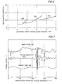
- FIG. 7 is a graph showing a comparison between amplitude, travel time, and phase contrast processing of data.
- FIG. 1 of the drawings where the numeral 10 identifies an acoustic measuring device supported in a sonde 12 in accordance with the teachings of the present disclosure.
- the sonde encloses a telemetry system 14 which provides an output signal on a logging cable 16 which extends to the surface.
- the sonde includes an antenna rotator 18 for rotating an antenna or transducer 20 in accordance with the present disclosure. It will be described in greater detail hereinafter.
- the antenna is mounted on a rotatable mechanism 22 so that the emitted acoustic pulse travels radially outwardly along a propagation line 24 and impinges on the sidewall 26 of the borehole.
- the sonde 12 is constructed with a housing 28 which is elongate and cylindrical.
- the antenna 20 is preferably submerged in the borehole fluid 30 to provide better acoustic coupling and reduced beam divergence than that offered by enclosing the transducer in an oil bath and utilizing a window for the acoustic energy to pass through.
- the conductor 16 extends to the surface where it passes over a sheave 38.
- the sheave 38 directs the logging cable 16 to a drum 40 where it is spooled for storage.
- the conductors in the cable 16 are connected with surface located electronics 42.
- the output data is displayed on a display 44.
- the data is recorded electronically 48, simultaneously with depth and time. The time is obtained from a real time clock 52 with millisecond resolution.
- the depth is provided by an electrical or mechanical depth measuring apparatus 46 which is connected with the sheave 38 and which also connects to the recorder 48.
- the present apparatus further includes acoustic electronics 50 which are supported in the sonde.
- the acoustic logging device 10 will be understood on explanation of the various components discussed below.
- the antenna 20 is better identified in FIGS. 2A and 2B of the drawings where it is shown to be a circular piezoelectric disk member 64. It is poled in the thickness mode, typically having both flat surfaces coated with a conducting metal electrode. It has a solid backing 70 which acts as a highly attenuative medium absorbing the acoustic energy which is radiated into it.
- the ceramic and backing are housed in an epoxy material 68 having a thickness separating the ceramic from the borehole fluid by a quarter wavelength.
- This material 68 having an intermediate acoustic impedance, is a well known technique for improving the transfer of acoustic energy from the ceramic which has a high impedance to the water (mud) which has a lower impedance.
- the total number of ring shaped areas is N where N is a whole number integer. Moreover, N is typically in the range of about three at the low end, and increases up to about ten. In theory, N can increase further, but there is a practical limit in the benefit obtained by increasing N. The optimum number for N is about three to eight.
- the rings are not evenly spaced radially but are spaced based upon a more subtle criterion. They are spaced such that when focused at the minimum range, the difference in time delay required for each ring is a fixed value. This procedure simplifies the electronics components somewhat. The delay differences for all of the ranges may be kept the same simplifying the electronic design. Even if respective delays are slightly imperfect, there is little degradation in the resulting focusing. There are other methodologies which may be used to select the spacings of the rings.
- the cuts are again 90 percent of the way through the solid ceramic body and are preferably less than 0.6 times the thickness of the ceramic in spacing.
- the electrodes of the individual square elements 74 are connected in FIG. 3C using small beads of silver epoxy, 76 to connect the correct pattern of square surfaces. Where a diagonal connection is required, a wire 78 is placed across the diagonal and silver epoxy 80 is used to bond it to the square element 74 and hold it above any elements it crosses without connection.
- the wires to the electronics are attached as shown in FIG. 2 .
- the resonant frequency of each square element is the same but slightly lower than the basic thickness resonance of the disk. The result is that each ring formed by the set of squares has the same resonant frequency and mechanical Q. Each of the rings therefore behaves almost identically in their source and receiver characteristics.
- the transmit focal distance is sent to the timing driver logic 82 which controls the N signals going to each of the N transmitter circuits 84.
- the transmit pulse is delayed by the decrease in travel time required for the acoustic energy to propagate from each ring to the desired focal depth as the ring diameter decreases.
- the outer ring typically has no delay, and the inner disk has the most delay.
- the signal out of the transmitter circuit 84 may be either a single pulse or a burst (typically a square wave) signal at the resonant frequency of the transducer.
- the N transmit-receive switches 94 are used to protect the N preamp circuits from the high voltage transmit pulse on the ceramic.
- the preamps 86 have typically 20 dB of gain to get the signal level up to a suitable level and have a lower output impedance than the ceramic, allowing them to drive the delay lines 88.
- the N multiple tap delay lines are used to compensate for the travel time differences of the signal at some focal distance propagating to each ring of the transducer. Again the signal from the center disk will be delayed the most since it will be the closest to the focus, and the outer ring signal will be delayed the least since it is the farthest from the focus. As the focal distance increases, the total range of delays decreases.
- the outputs of the taps of the delay line go into N sets of analog select gates 92. Although an arbitrarily large number of taps may be used, a number of from 3 to 10 is sufficient.
- the tap selection and thusly the receiver focal distance is controlled by the range select logic 90.
- the delay taps are thus selected such that the N signals coming from a chosen focal distance all appear at the outputs of the N analog select gates simultaneously.
- the N signals are summed in the summing amplifier 98 to produce the focused signal output 102.
- a second output 104 is also made available which is the signal from only the center element.
- the peak of the envelope of the signal 102 forms the amplitude signal.
- the time location of the onset of this signal is used to derive the travel time, indicating the range to the borehole wall. This forms the typical output signal provided to the surface through the telemetry so that the system presents an image of what is seen by the equipment in the borehole.
- the signal processing this signal 102 has been described in previous works.
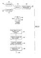
- the phase contrast imaging utilizes the signals 102 and 104. While the signal 102 represents the highly resolved beam and the signal 104 represents a less resolved beam, FIG. 5 shows one implementation of the phase contrast imaging process.
- the gain graph shows the spatial resolution of the two signals 102 and 104, where the curve 106 is the resolution of 102 and the curve 108 is the resolution of 104.
- both signals are digitized at about 20 times the resonant frequency of the transducer by the digitizers 112 and 114 and the data are stored in the memory 116.
- the two signals are then processed by a digital signal processor 118 to find the differences in arrival times.
- the signal processing sequence begins at the step 120 where the location of the peak of the high resolution signal is found.
- phase of both signals is then computed in the step 122, beginning in time where the envelope of the signal becomes greater than one-half the peak value until it drops in amplitude to below one-half the peak.
- the average phase difference over the measurement period is then computed in the step 124.
- These measurements may be filtered to pass high frequency content in the step 126 over the period of one revolution to remove the effects of the changes in the travel time to the borehole wall because of ellipticity or eccentering of the tool.
- the phase contrast data 128 may now be sent up hole and displayed as a gray scale image in place of the usual travel time image.
- FIG. 6 shows the 3 dB beam widths for three focal distances of a 2.5 inch diameter transducer operating at 280 kHz. When the transducer is focused at 2.4 inches, the three dB beam width is 0.22 inches according to the curve 130. As the distance to the target changes, the beam width increases significantly, as would the case be for a fixed focusing transducer.
- the fixed focus transducer would have a beam width of 0.55 inches.
- the electronically focused transducer could be refocused and produce a beam-width of 0.31 inches, see the curve 132. From this, it may be seen that the depth of field is relatively small when the transducer is focused at a short distance. This would indicate that a single fixed focus transducer would only work well when the distance to the borehole wall was close to the focal distance of the transducer.
- the focal distance can be changed to match the variations in the range to the sidewall with what ever precision is deemed suitable. It may be seen that, as the range increases to 6 inches, the focusing does not need to be changed by a distance shown in the curve 134, or about 10 inches as illustrated.
- the illustrated system is able to provide better and more detailed observation of events occurring in the borehole in that it presents surface detail data not otherwise obtainable heretofore.
- This enhanced sensitivity enables the device to present data with improved resolution and sensitivity.
- the depth of field is enhanced.
- the sensitivity of the system to variations in range is reduced, thereby enabling the device to operate over a wider dynamic range so that the greater irregularities in the borehole 26 can be observed.
- Dynamic focusing correction is markedly improved over the fixed focus system exemplified in UK patent 2,168,569A .
- the surface character measurement has also been enhanced.
- an impedance matching layer is added to the antenna (or "acoustic transducer” or “transducer”) 805.
- the acoustic transducer components are housed within a glass filled polyether ether keytone (“PEEK") housing 810.
- PEEK provides mechanical strength for the downhole drilling environment and has low loss acoustic properties.
- an epoxy or another material having acoustic properties that are intermediate between the impedance of the ceramic and the borehole fluid is used to construct the housing 810.
- the housing 810 provides one layer of acoustic impedance matching.
- an impedance matching layer 835 is provided between the piezoelectric ceramic disk 815 and the housing 810.
- the purpose of the impedance matching layer 835 is to provide a better match between the acoustic impedance of the piezoelectric ceramic disk 815, which is typically high, and the acoustic impedance of a fluid in a borehole, such as drilling mud or formation fluid, which is typically lower than that of the piezoelectric ceramic disk 815.
- the housing 810 provides an additional impedance matching layer which means that the acoustic transducer 805 has two impedance matching layers. In one embodiment: AIT > AI ⁇ 1 > AI ⁇ 2 > AIBF where:
- additional impedance matching layers are provided between the piezoelectric ceramic disk 815 and the housing 810.
- the acoustic impedance of the impedance matching layers generally increase the closer they are to the piezoelectric ceramic disk 815, although some deviation from this is envisioned. That is, the scope of the claims is intended to cover embodiments in which a small number of impedance matching layers relative to the total number of impedance matching layers do not strictly follow the monotonic change in acoustic impedance from the piezoelectric ceramic disk 815 to the housing.
- the impedance matching layer 835 is made of one part DURALCO® 4460 epoxy mixed with 68 parts hematite by weight.
- the particle size of the hematite is typical of that used in oil based drilling mud.
- the mixture is exposed to a vacuum until no bubbles are present in the mixture and molded onto a flat TEFLON® surface to an initial depth of 3 times the final thickness.
- the epoxy is cured at 180° F for 4 hours, then at 220° F for 4 hours.
- the lower density epoxy at the top is removed until the thickness is 1 ⁇ 4 wavelength at the center frequency of the transducer.
- the resulting material in this process has an acoustic impedance of 8.2 MRayls a density of 2.82 g/cm 3 and a sound velocity of 2900 m/sec.
- the surfaces of the resulting disk are finished flat and smooth and placed between the ceramic crystal and the PEEK housing.
- the piezoelectric ceramic disk 815 is supported by a backing material 840 that also absorbs acoustic energy traveling from the piezoelectric ceramic disk 815 away from the impedance matching layer 835.
- an epoxy casting resin 845 is used to close the housing and provide strain relief for the electrical conductors 850 attached to the piezoelectric ceramic disk 815.
- the connection of the electrical conductors 850 to the piezoelectric ceramic disk 815 is not shown in FIG. 8 but, in one embodiment, is similar to that shown in FIG. 2B .
- the impedance matching layer 940 is cut in the same way as illustrated in Fig. 3A .
- the cuts 925, 930, 935 are only partially through the impedance matching layer 940.
- the partial cuts are through the side closest to the housing 810. In one embodiment, the partial cuts are through the side closest to the piezoelectric crystal disk 815.
- the impedance matching layer 940 has N independent impedance matching layer regions that match and overlay the N independent transducer regions. That is, the four rings 905, 910, 915, 920 illustrated in FIG. 9B include rings cut in the piezoelectric ceramic disk 815 and matching and overlaying rings cut in the impedance matching layer 940.
- the regions in the impedance matching layer 940 match and cover the small squares, e.g. square 74, but are not connected together to form the regions (e.g., regions 1, 2, 3, 4, and 5).
- the piezoelectric ceramic disk 815 is cut as shown in Fig. 3A and connected into regions (e.g., regions 1, 2, 3, 4, and 5) illustrated in FIG. 3A using the techniques shown in FIG. 3C , and the impedance matching layer 940 is then applied and slots are cut into the impedance matching layer 940 to match the regions illustrated in FIG. 3A .
- the focus distance of the transducer 945 with an active surface diameter of 1.25 inches and a focus distance of 0.56 inches has an outer ring 920 width of 0.734 inches.
- the thickness of the ring when manufactured to be 1/4 wavelength thick at 350 kHz will be 0.0878 inches.
- the shear loading will significantly affect the energy coupled into the face of the transducer and eventually into the volume to be measured.
- a polymer with low shear stiffness or a fluid is inserted between adjacent phased-array elements of the piezoelectric ceramic disc 815, which improves the operating characteristics compared to a continuous layer. The process of cutting the intermediate layer to match the ceramic active areas allows the use of ceramic materials, which exhibit a smaller change in characteristics with temperature and lower acoustic loss than weighted polymers.
- the slots 925, 930, 935 improve the performance of the impedance matching layer 940 by eliminating the shear coupling between segments or rings of the impedance matching layer 940 that are not moving in the same direction. In one embodiment, the loss in signal amplitude due to unwanted shear loading is reduced.
- cutting the rings in the impedance matching layer 940 to reduce the coupling between the phased array elements is independent of how the ring electrodes are formed in the crystal. In other words, it is sometimes not necessary to cut groves in the crystal to create the ringed electrodes because of the properties of the crystal. That is, in one embodiment, the benefits of the impedance matching layer 940 are not dependent on how the phased array is formed in the crystal.
- the regions of the impedance matching layer 940 have the same acoustic impedance. In one embodiment, at least one of the regions of the impedance matching layer 940 has a different acoustic impedance than another of the regions of the impedance matching layer 940.
- the impedance matching layer 940 is formed using a protective face (e.g., PEEK) on the piezoelectric ceramic disk 815 with non-uniform thickness providing different matching layer impedances for the array elements.
- cutting slots into the impedance matching layer 940 significantly reduces the shear coupling between each signal path until the signal reaches the PEEK.
- the PEEK is not cut to withstand the harsh borehole environment and the loss is tolerated.
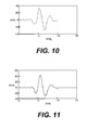
- FIGS. 10 and 11 show the difference in signal amplitude transmitted effected by changing from one layer of PEEK with optimum thickness ( FIG. 10 ) to a layer of PEEK and an optimized impedance matching layer 940 ( FIG. 11 ).
- the use of the extra impedance matching layer increases the signal amplitude by 2.5 dB for transmit signal.
- the overall improvement is 5 dB since the received signal also experiences the improvement.
- the sensitivity of the transducer is almost doubled by the addition of the impedance matching layer 940.
- the transducers 805 and 945 are used in measurement-while-drilling/logging-while-drilling ("MWD/LWD") systems, wired drillpipe systems, coiled tubing systems (wired and unwired), and wireline systems.
- MWD/LWD measurement-while-drilling/logging-while-drilling
- the electronics are powered by an onboard battery or by a generator, such as a mud generator.
- power is provided from the surface.
- all of the processing discussed above, such as that associated with FIG. 5 is done downhole. In one embodiment, the processing is done on the surface, for example by electronics 42 in FIG. 1 .
- the controller for the electronics shown in FIG. 5 is stored in the form of a computer program on a computer readable media 1205, such as a CD or DVD, as shown in Fig. 12 .
- a computer 1210 which may be the same as electronics 42 or acoustic electronics 50 (see FIG. 1 ), or which may be below the surface in the drill string, reads the computer program from the computer readable media 1205 through an input/output device 1215 and stores it in a memory 1220 where it is prepared for execution through compiling and linking, if necessary, and then executed.
- the system accepts inputs through an input/output device 1215, such as a keyboard, and provides outputs through an input/output device 1215, such as a monitor or printer.
- the system stores the results of calculations in memory 1220 or modifies such calculations that already exist in memory 1220.
- the results of calculations that reside in memory 1220 are made available through a network 1225 to a remote real time operating center 1230.
- the remote real time operating center 1230 makes the results of calculations available through a network 1235 to help in the planning of oil wells 1240 or in the drilling of oil wells 1240.
- Embodiment 1 A device comprising: (a) a piezoelectric transducer, the transducer having N independent transducer regions wherein N is an integer, each of the N independent transducer regions having a thickness, each of the N independent transducer regions having an acoustic impedance AIT, each of the N independent transducer regions being independently excitable to oscillate in the thickness mode when electrically excited by a potential difference applied across the thickness; (c) a first impedance matching layer having an acoustic impedance AI1 between AIT and a borehole fluid acoustic impedance AIBF, the first impedance matching layer being situated such that an acoustic signal emitted by the piezoelectric transducer will pass through the second impedance matching layer; and (b) a second impedance matching layer having an acoustic impedance AI2 between AI1 and AIBF, the second impedance matching layer being situated in the device such that an acoustic signal emitted by the trans
- Embodiment 2 The device of embodiment 1 wherein the second impedance matching layer comprises a housing.
- Embodiment 3 The device of embodiment 1 wherein the transducer is generally circularly disk shaped.
- Embodiment 4 The device of embodiment 1 wherein the N independent transducer regions are concentric and generally circumferential.
- Embodiment 5 The device of embodiment 1 wherein the first impedance matching layer has N independent first impedance matching layer regions that match and overlay the N independent transducer regions.
- Embodiment 6 The device of embodiment 5 wherein at least some of the N independent first impedance matching layer regions are mechanically decoupled from at least some of the other N independent first impedance matching layer regions.
- Embodiment 7 The device of embodiment 5 wherein the N independent first impedance matching layer regions are separated by cuts in the second impedance matching layer.
- Embodiment 8 The device of embodiment 5 wherein the acoustic impedances of the N independent first impedance matching layer regions are the same.
- Embodiment 9 The device of embodiment 5 wherein the acoustic impedance of at least one of the N independent first impedance matching layer regions is different from one other of the N independent first impedance matching layer regions.
- Embodiment 10 A method comprising: (a) emitting an acoustic pulse from a piezoelectric transducer, the transducer having N independent transducer regions wherein N is an integer, each of the N independent transducer regions having a thickness, each of the N independent transducer regions having an acoustic impedance AIT, each of the N independent transducer regions being independently excitable to oscillate in the thickness mode when electrically excited by a potential difference applied across the thickness; (c) passing the acoustic pulse through a first impedance matching layer having an acoustic impedance AI1 between AIT and a borehole fluid acoustic impedance AIBF; and (b) passing the acoustic pulse that has passed through the first impedance matching layer through a second impedance matching layer having an acoustic impedance AI2 between AI1 and AIBF.
- Embodiment 11 The method of embodiment 10 wherein the second impedance matching layer comprises a housing.
- Embodiment 12 The method of embodiment 10 wherein the transducer is generally circularly disk shaped.
- Embodiment 13 The method of embodiment 10 wherein the N independent transducer regions are concentric and generally circumferential.
- Embodiment 14 The method of embodiment 10 wherein the first impedance matching layer has N independent first impedance matching layer regions that match and overlay the N independent transducer regions.
- Embodiment 15 The method of embodiment 14 wherein at least some of the N independent first impedance matching layer regions are mechanically decoupled from at least some of the other N independent first impedance matching layer regions.
- Embodiment 17 The method of embodiment 14 wherein the acoustic impedances of the N independent first impedance matching layer regions are the same.
- Embodiment 18 The method of embodiment 14 wherein the acoustic impedance of at least one of the N independent first impedance matching layer regions is different from one other of the N independent first impedance matching layer regions.
- Embodiment 19 A device comprising: (a) a piezoelectric transducer having an acoustic impedance AIT; (c) a first impedance matching layer having an acoustic impedance AI1 between AIT and a borehole fluid acoustic impedance AIBF, the first impedance matching layer being situated such that an acoustic signal emitted by the piezoelectric transducer will pass through the second impedance matching layer, the first impedance matching layer having N independent impedance matching layer regions separated by cuts in the first impedance matching layer; and (b) a second impedance matching layer having an acoustic impedance AI2 between AI1 and AIBF, the second impedance matching layer being situated in the device such that an acoustic signal emitted by the transducer will pass through the second impedance matching layer after it passes through the first impedance matching layer.
- Embodiment 20 The device of embodiment 19 wherein: the piezoelectric transducer comprises N independent transducer regions wherein N is an integer, each of the N independent transducer regions having a thickness, each of the N independent transducer regions having an acoustic impedance AIT, each of the N independent transducer regions being independently excitable to oscillate in the thickness mode when electrically excited by a potential difference applied across the thickness, each of the N independent transducer regions being matched and overlaid by one of the N independent impedance matching layer regions.
Landscapes
- Engineering & Computer Science (AREA)
- Physics & Mathematics (AREA)
- Mechanical Engineering (AREA)
- Remote Sensing (AREA)
- Life Sciences & Earth Sciences (AREA)
- Acoustics & Sound (AREA)
- Environmental & Geological Engineering (AREA)
- Geology (AREA)
- General Life Sciences & Earth Sciences (AREA)
- General Physics & Mathematics (AREA)
- Geophysics (AREA)
- Multimedia (AREA)
- Geophysics And Detection Of Objects (AREA)
- Transducers For Ultrasonic Waves (AREA)
- Investigating Or Analyzing Materials By The Use Of Ultrasonic Waves (AREA)
Priority Applications (1)
| Application Number | Priority Date | Filing Date | Title |
|---|---|---|---|
| EP13179501.5A EP2662154B1 (fr) | 2011-02-15 | 2011-02-15 | Transducteur acoustique à couche d'adaptation à l'impédance |
Applications Claiming Priority (3)
| Application Number | Priority Date | Filing Date | Title |
|---|---|---|---|
| EP13179501.5A EP2662154B1 (fr) | 2011-02-15 | 2011-02-15 | Transducteur acoustique à couche d'adaptation à l'impédance |
| EP11858597.5A EP2603820B1 (fr) | 2011-02-15 | 2011-02-15 | Transducteur acoustique à couche d'adaptation à l'impédance |
| PCT/US2011/024841 WO2012112137A1 (fr) | 2011-02-15 | 2011-02-15 | Transducteur acoustique à couche d'adaptation à l'impédance |
Related Parent Applications (3)
| Application Number | Title | Priority Date | Filing Date |
|---|---|---|---|
| EP11858597.5A Division EP2603820B1 (fr) | 2011-02-15 | 2011-02-15 | Transducteur acoustique à couche d'adaptation à l'impédance |
| EP11858597.5A Division-Into EP2603820B1 (fr) | 2011-02-15 | 2011-02-15 | Transducteur acoustique à couche d'adaptation à l'impédance |
| EP11858597.5 Division | 2011-02-15 |
Publications (3)
| Publication Number | Publication Date |
|---|---|
| EP2662154A2 true EP2662154A2 (fr) | 2013-11-13 |
| EP2662154A3 EP2662154A3 (fr) | 2015-02-25 |
| EP2662154B1 EP2662154B1 (fr) | 2017-03-15 |
Family
ID=46672853
Family Applications (2)
| Application Number | Title | Priority Date | Filing Date |
|---|---|---|---|
| EP13179501.5A Not-in-force EP2662154B1 (fr) | 2011-02-15 | 2011-02-15 | Transducteur acoustique à couche d'adaptation à l'impédance |
| EP11858597.5A Active EP2603820B1 (fr) | 2011-02-15 | 2011-02-15 | Transducteur acoustique à couche d'adaptation à l'impédance |
Family Applications After (1)
| Application Number | Title | Priority Date | Filing Date |
|---|---|---|---|
| EP11858597.5A Active EP2603820B1 (fr) | 2011-02-15 | 2011-02-15 | Transducteur acoustique à couche d'adaptation à l'impédance |
Country Status (4)
| Country | Link |
|---|---|
| US (2) | US9079221B2 (fr) |
| EP (2) | EP2662154B1 (fr) |
| SG (1) | SG192762A1 (fr) |
| WO (1) | WO2012112137A1 (fr) |
Cited By (1)
| Publication number | Priority date | Publication date | Assignee | Title |
|---|---|---|---|---|
| US10191173B2 (en) | 2015-09-30 | 2019-01-29 | Schlumberger Technology Corporation | Systems and methods for evaluating annular material using beamforming from acoustic arrays |
Families Citing this family (24)
| Publication number | Priority date | Publication date | Assignee | Title |
|---|---|---|---|---|
| US9224938B2 (en) * | 2011-04-11 | 2015-12-29 | Halliburton Energy Services, Inc. | Piezoelectric element and method to remove extraneous vibration modes |
| US9050628B2 (en) | 2012-01-30 | 2015-06-09 | Piezotech Llc | Pulse-echo acoustic transducer |
| US11117166B2 (en) | 2015-05-22 | 2021-09-14 | Halliburton Energy Services, Inc. | Ultrasonic transducers with piezoelectric material embedded in backing |
| GB2554214A (en) * | 2015-05-22 | 2018-03-28 | Halliburton Energy Services Inc | In-situ borehole fluid speed and attenuation measurement in an ultrasonic scanning tool |
| EP3341563B1 (fr) * | 2015-10-02 | 2023-03-08 | Halliburton Energy Services, Inc. | Transducteur ultrasonique à élément de support amélioré |
| US10126454B2 (en) * | 2015-12-30 | 2018-11-13 | Schlumberger Technology Corporation | Method and system for fracture detection using acoustic waves |
| GB2563788B (en) * | 2016-03-04 | 2021-05-05 | Baker Hughes Oilfield Operations Llc | Method and system for controlling voltage applied across a piezoelectric stack of a downhole acoustic transmitter |
| US10710006B2 (en) * | 2016-04-25 | 2020-07-14 | Flodesign Sonics, Inc. | Piezoelectric transducer for generation of an acoustic standing wave |
| CN107543864B (zh) * | 2016-09-14 | 2020-01-03 | 北京卫星环境工程研究所 | 航天器泄漏定位用声阵列传感器 |
| US10921478B2 (en) | 2016-10-14 | 2021-02-16 | Halliburton Energy Services, Inc. | Method and transducer for acoustic logging |
| US10453821B2 (en) * | 2017-08-04 | 2019-10-22 | Samsung Electronics Co., Ltd. | Connection system of semiconductor packages |
| US11590535B2 (en) | 2017-10-25 | 2023-02-28 | Honeywell International Inc. | Ultrasonic transducer |
| CN107802969A (zh) * | 2017-11-13 | 2018-03-16 | 深圳市普罗医学股份有限公司 | 一种球面自聚焦超声相控阵列换能器 |
| US10335036B2 (en) | 2017-11-22 | 2019-07-02 | Hi Llc | Pulsed ultrasound modulated optical tomography using lock-in camera |
| US10016137B1 (en) | 2017-11-22 | 2018-07-10 | Hi Llc | System and method for simultaneously detecting phase modulated optical signals |
| US10219700B1 (en) | 2017-12-15 | 2019-03-05 | Hi Llc | Systems and methods for quasi-ballistic photon optical coherence tomography in diffusive scattering media using a lock-in camera detector |
| US10368752B1 (en) | 2018-03-08 | 2019-08-06 | Hi Llc | Devices and methods to convert conventional imagers into lock-in cameras |
| US11206985B2 (en) | 2018-04-13 | 2021-12-28 | Hi Llc | Non-invasive optical detection systems and methods in highly scattering medium |
| US11857316B2 (en) | 2018-05-07 | 2024-01-02 | Hi Llc | Non-invasive optical detection system and method |
| GB2589773B (en) * | 2018-06-15 | 2023-02-22 | Baker Hughes Holdings Llc | Through tubing acoustic imaging |
| WO2019241669A1 (fr) * | 2018-06-15 | 2019-12-19 | Baker Hughes, A Ge Company, Llc | Imagerie acoustique à travers un tubage |
| US11480702B2 (en) | 2018-06-27 | 2022-10-25 | Halliburton Energy Services, Inc. | Ultrasonic transducer with reduced backing reflection |
| CN109060110A (zh) * | 2018-10-19 | 2018-12-21 | 海鹰企业集团有限责任公司 | 一种小体积、高接收灵敏度的压电圆管水听器 |
| US11807142B2 (en) | 2019-03-06 | 2023-11-07 | Lear Corporation | Electrical track assembly |
Citations (2)
| Publication number | Priority date | Publication date | Assignee | Title |
|---|---|---|---|---|
| GB2168569A (en) | 1984-12-17 | 1986-06-18 | Shell Int Research | Transducer for use with borehole televiewer logging tool |
| US5044462A (en) | 1990-07-31 | 1991-09-03 | Halliburton Logging Services, Inc. | Focused planar transducer |
Family Cites Families (41)
| Publication number | Priority date | Publication date | Assignee | Title |
|---|---|---|---|---|
| BE551765A (fr) | 1955-10-13 | |||
| US3138219A (en) | 1959-07-28 | 1964-06-23 | Schlumberger Well Surv Corp | Electroacoustic transducer apparatus |
| US3225728A (en) | 1963-10-08 | 1965-12-28 | Nomura Suetsugu | Hulled body equipped with wave-riding device |
| US4297607A (en) * | 1980-04-25 | 1981-10-27 | Panametrics, Inc. | Sealed, matched piezoelectric transducer |
| DE3501808A1 (de) * | 1985-01-21 | 1986-07-24 | Siemens AG, 1000 Berlin und 8000 München | Ultraschallwandler |
| CN85100483B (zh) | 1985-04-01 | 1988-10-19 | 上海灯泡厂 | 超声波换能器用背载材料 |
| US5852587A (en) | 1988-12-22 | 1998-12-22 | Schlumberger Technology Corporation | Method of and apparatus for sonic logging while drilling a borehole traversing an earth formation |
| US5400788A (en) | 1989-05-16 | 1995-03-28 | Hewlett-Packard | Apparatus that generates acoustic signals at discrete multiple frequencies and that couples acoustic signals into a cladded-core acoustic waveguide |
| US5130950A (en) | 1990-05-16 | 1992-07-14 | Schlumberger Technology Corporation | Ultrasonic measurement apparatus |
| US5343443A (en) | 1990-10-15 | 1994-08-30 | Rowe, Deines Instruments, Inc. | Broadband acoustic transducer |
| US6225728B1 (en) * | 1994-08-18 | 2001-05-01 | Agilent Technologies, Inc. | Composite piezoelectric transducer arrays with improved acoustical and electrical impedance |
| US5488954A (en) | 1994-09-09 | 1996-02-06 | Georgia Tech Research Corp. | Ultrasonic transducer and method for using same |
| US6188643B1 (en) | 1994-10-13 | 2001-02-13 | Schlumberger Technology Corporation | Method and apparatus for inspecting well bore casing |
| US5644186A (en) | 1995-06-07 | 1997-07-01 | Halliburton Company | Acoustic Transducer for LWD tool |
| US6213250B1 (en) | 1998-09-25 | 2001-04-10 | Dresser Industries, Inc. | Transducer for acoustic logging |
| US6354146B1 (en) | 1999-06-17 | 2002-03-12 | Halliburton Energy Services, Inc. | Acoustic transducer system for monitoring well production |
| US6307302B1 (en) | 1999-07-23 | 2001-10-23 | Measurement Specialities, Inc. | Ultrasonic transducer having impedance matching layer |
| US6466513B1 (en) | 1999-10-21 | 2002-10-15 | Schlumberger Technology Corporation | Acoustic sensor assembly |
| US6371915B1 (en) * | 1999-11-02 | 2002-04-16 | Scimed Life Systems, Inc. | One-twelfth wavelength impedence matching transformer |
| US6589174B1 (en) | 2000-10-20 | 2003-07-08 | Sunnybrook & Women's College Health Sciences Centre | Technique and apparatus for ultrasound therapy |
| US6822374B1 (en) | 2000-11-15 | 2004-11-23 | General Electric Company | Multilayer piezoelectric structure with uniform electric field |
| US6470749B1 (en) | 2001-05-08 | 2002-10-29 | Halliburton Energy Services, Inc. | Method and apparatus for pulsed ultrasonic doppler measurement of wall deposition |
| US6513385B1 (en) | 2001-05-08 | 2003-02-04 | Halliburton Energy Services, Inc. | Acoustic sensor for pipeline deposition characterization and monitoring |
| KR20040086504A (ko) | 2002-01-28 | 2004-10-11 | 마츠시타 덴끼 산교 가부시키가이샤 | 음향 정합층, 초음파 송수파기 및 이들의 제조 방법, 및초음파 유량계 |
| US6788620B2 (en) | 2002-05-15 | 2004-09-07 | Matsushita Electric Industrial Co Ltd | Acoustic matching member, ultrasound transducer, ultrasonic flowmeter and method for manufacturing the same |
| US20040095847A1 (en) | 2002-11-18 | 2004-05-20 | Baker Hughes Incorporated | Acoustic devices to measure ultrasound velocity in drilling mud |
| US7513147B2 (en) * | 2003-07-03 | 2009-04-07 | Pathfinder Energy Services, Inc. | Piezocomposite transducer for a downhole measurement tool |
| US7075215B2 (en) | 2003-07-03 | 2006-07-11 | Pathfinder Energy Services, Inc. | Matching layer assembly for a downhole acoustic sensor |
| US6995500B2 (en) | 2003-07-03 | 2006-02-07 | Pathfinder Energy Services, Inc. | Composite backing layer for a downhole acoustic sensor |
| US7036363B2 (en) * | 2003-07-03 | 2006-05-02 | Pathfinder Energy Services, Inc. | Acoustic sensor for downhole measurement tool |
| US7117743B2 (en) * | 2003-07-31 | 2006-10-10 | Hewlett-Packard Development Company, L.P. | Multiple-transducer sensor system and method with selective activation and isolation of individual transducers |
| US20050184620A1 (en) | 2004-02-19 | 2005-08-25 | Kaitec Inc. | Simple method of designing acoustic matching layers in thickness-mode piezoelectric transducers |
| US7356905B2 (en) | 2004-05-25 | 2008-04-15 | Riverside Research Institute | Method of fabricating a high frequency ultrasound transducer |
| JP4746302B2 (ja) | 2004-10-05 | 2011-08-10 | オリンパス株式会社 | 超音波探触子 |
| US20070093702A1 (en) | 2005-10-26 | 2007-04-26 | Skyline Biomedical, Inc. | Apparatus and method for non-invasive and minimally-invasive sensing of parameters relating to blood |
| US7587936B2 (en) * | 2007-02-01 | 2009-09-15 | Smith International Inc. | Apparatus and method for determining drilling fluid acoustic properties |
| US7557490B2 (en) * | 2007-05-10 | 2009-07-07 | Daniel Measurement & Control, Inc. | Systems and methods of a transducer having a plastic matching layer |
| US8260554B2 (en) * | 2008-02-29 | 2012-09-04 | Halliburton Energy Services, Inc. | Apparatus and method for motion correction to sensor measurements |
| US8129886B2 (en) * | 2008-02-29 | 2012-03-06 | General Electric Company | Apparatus and method for increasing sensitivity of ultrasound transducers |
| US8232705B2 (en) * | 2010-07-09 | 2012-07-31 | General Electric Company | Thermal transfer and acoustic matching layers for ultrasound transducer |
| US8378557B2 (en) * | 2010-07-09 | 2013-02-19 | General Electric Company | Thermal transfer and acoustic matching layers for ultrasound transducer |
-
2011
- 2011-02-15 WO PCT/US2011/024841 patent/WO2012112137A1/fr not_active Ceased
- 2011-02-15 US US13/984,716 patent/US9079221B2/en active Active
- 2011-02-15 SG SG2013061593A patent/SG192762A1/en unknown
- 2011-02-15 EP EP13179501.5A patent/EP2662154B1/fr not_active Not-in-force
- 2011-02-15 EP EP11858597.5A patent/EP2603820B1/fr active Active
-
2015
- 2015-05-15 US US14/713,822 patent/US9555444B2/en active Active
Patent Citations (2)
| Publication number | Priority date | Publication date | Assignee | Title |
|---|---|---|---|---|
| GB2168569A (en) | 1984-12-17 | 1986-06-18 | Shell Int Research | Transducer for use with borehole televiewer logging tool |
| US5044462A (en) | 1990-07-31 | 1991-09-03 | Halliburton Logging Services, Inc. | Focused planar transducer |
Cited By (1)
| Publication number | Priority date | Publication date | Assignee | Title |
|---|---|---|---|---|
| US10191173B2 (en) | 2015-09-30 | 2019-01-29 | Schlumberger Technology Corporation | Systems and methods for evaluating annular material using beamforming from acoustic arrays |
Also Published As
| Publication number | Publication date |
|---|---|
| EP2662154A3 (fr) | 2015-02-25 |
| US20160016199A1 (en) | 2016-01-21 |
| US9555444B2 (en) | 2017-01-31 |
| EP2603820A4 (fr) | 2015-02-25 |
| EP2662154B1 (fr) | 2017-03-15 |
| WO2012112137A1 (fr) | 2012-08-23 |
| SG192762A1 (en) | 2013-09-30 |
| EP2603820B1 (fr) | 2019-03-20 |
| US9079221B2 (en) | 2015-07-14 |
| EP2603820A1 (fr) | 2013-06-19 |
| US20130327139A1 (en) | 2013-12-12 |
Similar Documents
| Publication | Publication Date | Title |
|---|---|---|
| EP2603820B1 (fr) | Transducteur acoustique à couche d'adaptation à l'impédance | |
| EP3092369B1 (fr) | Dispositifs et procédés pour l'imagerie acoustique de fond | |
| CA2145006C (fr) | Methode et dispositif de guidage de faisceau et d'ombrage bessel pour un reseau | |
| US9363605B2 (en) | Focused acoustic transducer | |
| US7460435B2 (en) | Acoustic transducers for tubulars | |
| EP3862796B1 (fr) | Reconfiguration en temps réel d'opération de réseau à commande de phase | |
| US5044462A (en) | Focused planar transducer | |
| JP5816275B2 (ja) | ボアホールにおいて音響エネルギーのビームを生成する装置及び方法並びにそれらの応用 | |
| US9260958B2 (en) | System and method for acoustic imaging using a transducer array | |
| AU2011261798B2 (en) | Device and method for generating a collimated beam of acoustic energy in a borehole | |
| JP5799088B2 (ja) | ボアホールにおいて音響エネルギーのビームを生成する装置及び方法並びにそれらの応用 | |
| NO20210129A1 (en) | Through tubing cement evaluation using seismic methods | |
| MXPA04006579A (es) | Herramienta acustica para el registro de datos que tiene una fuente programable en forma de ondas. | |
| WO2009108889A2 (fr) | Transducteur composite d’imagerie ultrasonore et de mesure d’épaisseur de fond de puits | |
| AU2008202763A1 (en) | Acoustic transmitter comprising a plurality of piezoelectric plates | |
| MXPA05000317A (es) | Aparato para perforacion de pozo con cubiertas deslizantes. | |
| Tan et al. | Research on acoustic logging while drilling transmitting technologies | |
| EP2468424A2 (fr) | Transducteur ultrasonique monodirectionnel pour imagerie de forage | |
| US20100149914A1 (en) | Multi-frequency borehole imager | |
| CA2185412A1 (fr) | Methode et appareil pour diagraphie de sondages par reflexion acoustique | |
| NL9900024A (nl) | Werkwijze en inrichting voor bundelbesturing en Bessel-schaduwen van conformeel array. |
Legal Events
| Date | Code | Title | Description |
|---|---|---|---|
| PUAI | Public reference made under article 153(3) epc to a published international application that has entered the european phase |
Free format text: ORIGINAL CODE: 0009012 |
|
| AC | Divisional application: reference to earlier application |
Ref document number: 2603820 Country of ref document: EP Kind code of ref document: P |
|
| AK | Designated contracting states |
Kind code of ref document: A2 Designated state(s): AL AT BE BG CH CY CZ DE DK EE ES FI FR GB GR HR HU IE IS IT LI LT LU LV MC MK MT NL NO PL PT RO RS SE SI SK SM TR |
|
| AX | Request for extension of the european patent |
Extension state: BA ME |
|
| RIN1 | Information on inventor provided before grant (corrected) |
Inventor name: MAKI, VOLDI, E., JR. Inventor name: GOODMAN, GEORGE DAVID |
|
| PUAL | Search report despatched |
Free format text: ORIGINAL CODE: 0009013 |
|
| AK | Designated contracting states |
Kind code of ref document: A3 Designated state(s): AL AT BE BG CH CY CZ DE DK EE ES FI FR GB GR HR HU IE IS IT LI LT LU LV MC MK MT NL NO PL PT RO RS SE SI SK SM TR |
|
| AX | Request for extension of the european patent |
Extension state: BA ME |
|
| RIC1 | Information provided on ipc code assigned before grant |
Ipc: G10K 11/02 20060101ALI20150119BHEP Ipc: G01V 1/40 20060101ALI20150119BHEP Ipc: B06B 1/06 20060101AFI20150119BHEP Ipc: G01V 1/02 20060101ALI20150119BHEP |
|
| 17P | Request for examination filed |
Effective date: 20150813 |
|
| RBV | Designated contracting states (corrected) |
Designated state(s): AL AT BE BG CH CY CZ DE DK EE ES FI FR GB GR HR HU IE IS IT LI LT LU LV MC MK MT NL NO PL PT RO RS SE SI SK SM TR |
|
| GRAP | Despatch of communication of intention to grant a patent |
Free format text: ORIGINAL CODE: EPIDOSNIGR1 |
|
| RIC1 | Information provided on ipc code assigned before grant |
Ipc: G01V 1/02 20060101ALI20160118BHEP Ipc: G01V 1/40 20060101ALI20160118BHEP Ipc: G10K 11/02 20060101ALI20160118BHEP Ipc: B06B 1/06 20060101AFI20160118BHEP |
|
| INTG | Intention to grant announced |
Effective date: 20160218 |
|
| RIN1 | Information on inventor provided before grant (corrected) |
Inventor name: MAKI, VOLDI, E., JR. Inventor name: GOODMAN, GEORGE DAVID |
|
| GRAJ | Information related to disapproval of communication of intention to grant by the applicant or resumption of examination proceedings by the epo deleted |
Free format text: ORIGINAL CODE: EPIDOSDIGR1 |
|
| INTC | Intention to grant announced (deleted) | ||
| GRAP | Despatch of communication of intention to grant a patent |
Free format text: ORIGINAL CODE: EPIDOSNIGR1 |
|
| INTG | Intention to grant announced |
Effective date: 20160914 |
|
| GRAJ | Information related to disapproval of communication of intention to grant by the applicant or resumption of examination proceedings by the epo deleted |
Free format text: ORIGINAL CODE: EPIDOSDIGR1 |
|
| GRAP | Despatch of communication of intention to grant a patent |
Free format text: ORIGINAL CODE: EPIDOSNIGR1 |
|
| STAA | Information on the status of an ep patent application or granted ep patent |
Free format text: STATUS: GRANT OF PATENT IS INTENDED |
|
| INTC | Intention to grant announced (deleted) | ||
| INTG | Intention to grant announced |
Effective date: 20161109 |
|
| GRAS | Grant fee paid |
Free format text: ORIGINAL CODE: EPIDOSNIGR3 |
|
| GRAA | (expected) grant |
Free format text: ORIGINAL CODE: 0009210 |
|
| STAA | Information on the status of an ep patent application or granted ep patent |
Free format text: STATUS: THE PATENT HAS BEEN GRANTED |
|
| AC | Divisional application: reference to earlier application |
Ref document number: 2603820 Country of ref document: EP Kind code of ref document: P |
|
| AK | Designated contracting states |
Kind code of ref document: B1 Designated state(s): AL AT BE BG CH CY CZ DE DK EE ES FI FR GB GR HR HU IE IS IT LI LT LU LV MC MK MT NL NO PL PT RO RS SE SI SK SM TR |
|
| REG | Reference to a national code |
Ref country code: CH Ref legal event code: EP Ref country code: GB Ref legal event code: FG4D |
|
| REG | Reference to a national code |
Ref country code: IE Ref legal event code: FG4D |
|
| REG | Reference to a national code |
Ref country code: AT Ref legal event code: REF Ref document number: 875006 Country of ref document: AT Kind code of ref document: T Effective date: 20170415 |
|
| REG | Reference to a national code |
Ref country code: DE Ref legal event code: R096 Ref document number: 602011036107 Country of ref document: DE |
|
| REG | Reference to a national code |
Ref country code: NO Ref legal event code: T2 Effective date: 20170315 |
|
| REG | Reference to a national code |
Ref country code: NL Ref legal event code: MP Effective date: 20170315 |
|
| REG | Reference to a national code |
Ref country code: LT Ref legal event code: MG4D |
|
| PG25 | Lapsed in a contracting state [announced via postgrant information from national office to epo] |
Ref country code: GR Free format text: LAPSE BECAUSE OF FAILURE TO SUBMIT A TRANSLATION OF THE DESCRIPTION OR TO PAY THE FEE WITHIN THE PRESCRIBED TIME-LIMIT Effective date: 20170616 Ref country code: HR Free format text: LAPSE BECAUSE OF FAILURE TO SUBMIT A TRANSLATION OF THE DESCRIPTION OR TO PAY THE FEE WITHIN THE PRESCRIBED TIME-LIMIT Effective date: 20170315 Ref country code: FI Free format text: LAPSE BECAUSE OF FAILURE TO SUBMIT A TRANSLATION OF THE DESCRIPTION OR TO PAY THE FEE WITHIN THE PRESCRIBED TIME-LIMIT Effective date: 20170315 Ref country code: LT Free format text: LAPSE BECAUSE OF FAILURE TO SUBMIT A TRANSLATION OF THE DESCRIPTION OR TO PAY THE FEE WITHIN THE PRESCRIBED TIME-LIMIT Effective date: 20170315 |
|
| REG | Reference to a national code |
Ref country code: AT Ref legal event code: MK05 Ref document number: 875006 Country of ref document: AT Kind code of ref document: T Effective date: 20170315 |
|
| PG25 | Lapsed in a contracting state [announced via postgrant information from national office to epo] |
Ref country code: SE Free format text: LAPSE BECAUSE OF FAILURE TO SUBMIT A TRANSLATION OF THE DESCRIPTION OR TO PAY THE FEE WITHIN THE PRESCRIBED TIME-LIMIT Effective date: 20170315 Ref country code: LV Free format text: LAPSE BECAUSE OF FAILURE TO SUBMIT A TRANSLATION OF THE DESCRIPTION OR TO PAY THE FEE WITHIN THE PRESCRIBED TIME-LIMIT Effective date: 20170315 Ref country code: BG Free format text: LAPSE BECAUSE OF FAILURE TO SUBMIT A TRANSLATION OF THE DESCRIPTION OR TO PAY THE FEE WITHIN THE PRESCRIBED TIME-LIMIT Effective date: 20170615 Ref country code: RS Free format text: LAPSE BECAUSE OF FAILURE TO SUBMIT A TRANSLATION OF THE DESCRIPTION OR TO PAY THE FEE WITHIN THE PRESCRIBED TIME-LIMIT Effective date: 20170315 |
|
| PG25 | Lapsed in a contracting state [announced via postgrant information from national office to epo] |
Ref country code: NL Free format text: LAPSE BECAUSE OF FAILURE TO SUBMIT A TRANSLATION OF THE DESCRIPTION OR TO PAY THE FEE WITHIN THE PRESCRIBED TIME-LIMIT Effective date: 20170315 |
|
| PG25 | Lapsed in a contracting state [announced via postgrant information from national office to epo] |
Ref country code: CZ Free format text: LAPSE BECAUSE OF FAILURE TO SUBMIT A TRANSLATION OF THE DESCRIPTION OR TO PAY THE FEE WITHIN THE PRESCRIBED TIME-LIMIT Effective date: 20170315 Ref country code: EE Free format text: LAPSE BECAUSE OF FAILURE TO SUBMIT A TRANSLATION OF THE DESCRIPTION OR TO PAY THE FEE WITHIN THE PRESCRIBED TIME-LIMIT Effective date: 20170315 Ref country code: SK Free format text: LAPSE BECAUSE OF FAILURE TO SUBMIT A TRANSLATION OF THE DESCRIPTION OR TO PAY THE FEE WITHIN THE PRESCRIBED TIME-LIMIT Effective date: 20170315 Ref country code: ES Free format text: LAPSE BECAUSE OF FAILURE TO SUBMIT A TRANSLATION OF THE DESCRIPTION OR TO PAY THE FEE WITHIN THE PRESCRIBED TIME-LIMIT Effective date: 20170315 Ref country code: RO Free format text: LAPSE BECAUSE OF FAILURE TO SUBMIT A TRANSLATION OF THE DESCRIPTION OR TO PAY THE FEE WITHIN THE PRESCRIBED TIME-LIMIT Effective date: 20170315 Ref country code: AT Free format text: LAPSE BECAUSE OF FAILURE TO SUBMIT A TRANSLATION OF THE DESCRIPTION OR TO PAY THE FEE WITHIN THE PRESCRIBED TIME-LIMIT Effective date: 20170315 |
|
| PG25 | Lapsed in a contracting state [announced via postgrant information from national office to epo] |
Ref country code: IS Free format text: LAPSE BECAUSE OF FAILURE TO SUBMIT A TRANSLATION OF THE DESCRIPTION OR TO PAY THE FEE WITHIN THE PRESCRIBED TIME-LIMIT Effective date: 20170715 Ref country code: PL Free format text: LAPSE BECAUSE OF FAILURE TO SUBMIT A TRANSLATION OF THE DESCRIPTION OR TO PAY THE FEE WITHIN THE PRESCRIBED TIME-LIMIT Effective date: 20170315 Ref country code: SM Free format text: LAPSE BECAUSE OF FAILURE TO SUBMIT A TRANSLATION OF THE DESCRIPTION OR TO PAY THE FEE WITHIN THE PRESCRIBED TIME-LIMIT Effective date: 20170315 Ref country code: PT Free format text: LAPSE BECAUSE OF FAILURE TO SUBMIT A TRANSLATION OF THE DESCRIPTION OR TO PAY THE FEE WITHIN THE PRESCRIBED TIME-LIMIT Effective date: 20170717 |
|
| REG | Reference to a national code |
Ref country code: DE Ref legal event code: R097 Ref document number: 602011036107 Country of ref document: DE |
|
| PLBE | No opposition filed within time limit |
Free format text: ORIGINAL CODE: 0009261 |
|
| STAA | Information on the status of an ep patent application or granted ep patent |
Free format text: STATUS: NO OPPOSITION FILED WITHIN TIME LIMIT |
|
| PG25 | Lapsed in a contracting state [announced via postgrant information from national office to epo] |
Ref country code: DK Free format text: LAPSE BECAUSE OF FAILURE TO SUBMIT A TRANSLATION OF THE DESCRIPTION OR TO PAY THE FEE WITHIN THE PRESCRIBED TIME-LIMIT Effective date: 20170315 |
|
| 26N | No opposition filed |
Effective date: 20171218 |
|
| PG25 | Lapsed in a contracting state [announced via postgrant information from national office to epo] |
Ref country code: IT Free format text: LAPSE BECAUSE OF FAILURE TO SUBMIT A TRANSLATION OF THE DESCRIPTION OR TO PAY THE FEE WITHIN THE PRESCRIBED TIME-LIMIT Effective date: 20170315 Ref country code: SI Free format text: LAPSE BECAUSE OF FAILURE TO SUBMIT A TRANSLATION OF THE DESCRIPTION OR TO PAY THE FEE WITHIN THE PRESCRIBED TIME-LIMIT Effective date: 20170315 |
|
| REG | Reference to a national code |
Ref country code: DE Ref legal event code: R119 Ref document number: 602011036107 Country of ref document: DE |
|
| REG | Reference to a national code |
Ref country code: CH Ref legal event code: PL |
|
| PG25 | Lapsed in a contracting state [announced via postgrant information from national office to epo] |
Ref country code: MC Free format text: LAPSE BECAUSE OF FAILURE TO SUBMIT A TRANSLATION OF THE DESCRIPTION OR TO PAY THE FEE WITHIN THE PRESCRIBED TIME-LIMIT Effective date: 20170315 |
|
| REG | Reference to a national code |
Ref country code: IE Ref legal event code: MM4A |
|
| REG | Reference to a national code |
Ref country code: BE Ref legal event code: MM Effective date: 20180228 |
|
| PG25 | Lapsed in a contracting state [announced via postgrant information from national office to epo] |
Ref country code: LI Free format text: LAPSE BECAUSE OF NON-PAYMENT OF DUE FEES Effective date: 20180228 Ref country code: LU Free format text: LAPSE BECAUSE OF NON-PAYMENT OF DUE FEES Effective date: 20180215 Ref country code: CH Free format text: LAPSE BECAUSE OF NON-PAYMENT OF DUE FEES Effective date: 20180228 |
|
| REG | Reference to a national code |
Ref country code: FR Ref legal event code: ST Effective date: 20181031 |
|
| PG25 | Lapsed in a contracting state [announced via postgrant information from national office to epo] |
Ref country code: DE Free format text: LAPSE BECAUSE OF NON-PAYMENT OF DUE FEES Effective date: 20180901 Ref country code: IE Free format text: LAPSE BECAUSE OF NON-PAYMENT OF DUE FEES Effective date: 20180215 |
|
| PG25 | Lapsed in a contracting state [announced via postgrant information from national office to epo] |
Ref country code: FR Free format text: LAPSE BECAUSE OF NON-PAYMENT OF DUE FEES Effective date: 20180228 Ref country code: BE Free format text: LAPSE BECAUSE OF NON-PAYMENT OF DUE FEES Effective date: 20180228 |
|
| PG25 | Lapsed in a contracting state [announced via postgrant information from national office to epo] |
Ref country code: MT Free format text: LAPSE BECAUSE OF NON-PAYMENT OF DUE FEES Effective date: 20180215 |
|
| PG25 | Lapsed in a contracting state [announced via postgrant information from national office to epo] |
Ref country code: TR Free format text: LAPSE BECAUSE OF FAILURE TO SUBMIT A TRANSLATION OF THE DESCRIPTION OR TO PAY THE FEE WITHIN THE PRESCRIBED TIME-LIMIT Effective date: 20170315 |
|
| PG25 | Lapsed in a contracting state [announced via postgrant information from national office to epo] |
Ref country code: HU Free format text: LAPSE BECAUSE OF FAILURE TO SUBMIT A TRANSLATION OF THE DESCRIPTION OR TO PAY THE FEE WITHIN THE PRESCRIBED TIME-LIMIT; INVALID AB INITIO Effective date: 20110215 |
|
| PG25 | Lapsed in a contracting state [announced via postgrant information from national office to epo] |
Ref country code: CY Free format text: LAPSE BECAUSE OF FAILURE TO SUBMIT A TRANSLATION OF THE DESCRIPTION OR TO PAY THE FEE WITHIN THE PRESCRIBED TIME-LIMIT Effective date: 20170315 Ref country code: MK Free format text: LAPSE BECAUSE OF NON-PAYMENT OF DUE FEES Effective date: 20170315 |
|
| PG25 | Lapsed in a contracting state [announced via postgrant information from national office to epo] |
Ref country code: AL Free format text: LAPSE BECAUSE OF FAILURE TO SUBMIT A TRANSLATION OF THE DESCRIPTION OR TO PAY THE FEE WITHIN THE PRESCRIBED TIME-LIMIT Effective date: 20170315 |
|
| PGFP | Annual fee paid to national office [announced via postgrant information from national office to epo] |
Ref country code: GB Payment date: 20231205 Year of fee payment: 14 |
|
| PGFP | Annual fee paid to national office [announced via postgrant information from national office to epo] |
Ref country code: NO Payment date: 20240125 Year of fee payment: 14 |
|
| PG25 | Lapsed in a contracting state [announced via postgrant information from national office to epo] |
Ref country code: NO Free format text: LAPSE BECAUSE OF NON-PAYMENT OF DUE FEES Effective date: 20250228 |
|
| GBPC | Gb: european patent ceased through non-payment of renewal fee |
Effective date: 20250215 |
|
| PG25 | Lapsed in a contracting state [announced via postgrant information from national office to epo] |
Ref country code: GB Free format text: LAPSE BECAUSE OF NON-PAYMENT OF DUE FEES Effective date: 20250215 |