EP2662207B1 - Aéro-structures ventilées, aéronef et procédés associés - Google Patents
Aéro-structures ventilées, aéronef et procédés associés Download PDFInfo
- Publication number
- EP2662207B1 EP2662207B1 EP13167336.0A EP13167336A EP2662207B1 EP 2662207 B1 EP2662207 B1 EP 2662207B1 EP 13167336 A EP13167336 A EP 13167336A EP 2662207 B1 EP2662207 B1 EP 2662207B1
- Authority
- EP
- European Patent Office
- Prior art keywords
- adherence
- micro
- aero
- ventilated
- lattice structure
- Prior art date
- Legal status (The legal status is an assumption and is not a legal conclusion. Google has not performed a legal analysis and makes no representation as to the accuracy of the status listed.)
- Active
Links
Images

Classifications
-
- B—PERFORMING OPERATIONS; TRANSPORTING
- B32—LAYERED PRODUCTS
- B32B—LAYERED PRODUCTS, i.e. PRODUCTS BUILT-UP OF STRATA OF FLAT OR NON-FLAT, e.g. CELLULAR OR HONEYCOMB, FORM
- B32B3/00—Layered products comprising a layer with external or internal discontinuities or unevennesses, or a layer of non-planar shape; Layered products comprising a layer having particular features of form
- B32B3/26—Layered products comprising a layer with external or internal discontinuities or unevennesses, or a layer of non-planar shape; Layered products comprising a layer having particular features of form characterised by a particular shape of the outline of the cross-section of a continuous layer; characterised by a layer with cavities or internal voids ; characterised by an apertured layer
- B32B3/28—Layered products comprising a layer with external or internal discontinuities or unevennesses, or a layer of non-planar shape; Layered products comprising a layer having particular features of form characterised by a particular shape of the outline of the cross-section of a continuous layer; characterised by a layer with cavities or internal voids ; characterised by an apertured layer characterised by a layer comprising a deformed thin sheet, i.e. the layer having its entire thickness deformed out of the plane, e.g. corrugated, crumpled
-
- B—PERFORMING OPERATIONS; TRANSPORTING
- B64—AIRCRAFT; AVIATION; COSMONAUTICS
- B64C—AEROPLANES; HELICOPTERS
- B64C3/00—Wings
- B64C3/20—Integral or sandwich constructions
-
- B—PERFORMING OPERATIONS; TRANSPORTING
- B32—LAYERED PRODUCTS
- B32B—LAYERED PRODUCTS, i.e. PRODUCTS BUILT-UP OF STRATA OF FLAT OR NON-FLAT, e.g. CELLULAR OR HONEYCOMB, FORM
- B32B3/00—Layered products comprising a layer with external or internal discontinuities or unevennesses, or a layer of non-planar shape; Layered products comprising a layer having particular features of form
- B32B3/10—Layered products comprising a layer with external or internal discontinuities or unevennesses, or a layer of non-planar shape; Layered products comprising a layer having particular features of form characterised by a discontinuous layer, i.e. formed of separate pieces of material
- B32B3/12—Layered products comprising a layer with external or internal discontinuities or unevennesses, or a layer of non-planar shape; Layered products comprising a layer having particular features of form characterised by a discontinuous layer, i.e. formed of separate pieces of material characterised by a layer of regularly- arranged cells, e.g. a honeycomb structure
-
- B—PERFORMING OPERATIONS; TRANSPORTING
- B64—AIRCRAFT; AVIATION; COSMONAUTICS
- B64C—AEROPLANES; HELICOPTERS
- B64C3/00—Wings
- B64C3/26—Construction, shape, or attachment of separate skins, e.g. panels
-
- B—PERFORMING OPERATIONS; TRANSPORTING
- B32—LAYERED PRODUCTS
- B32B—LAYERED PRODUCTS, i.e. PRODUCTS BUILT-UP OF STRATA OF FLAT OR NON-FLAT, e.g. CELLULAR OR HONEYCOMB, FORM
- B32B2305/00—Condition, form or state of the layers or laminate
- B32B2305/02—Cellular or porous
- B32B2305/024—Honeycomb
-
- B—PERFORMING OPERATIONS; TRANSPORTING
- B32—LAYERED PRODUCTS
- B32B—LAYERED PRODUCTS, i.e. PRODUCTS BUILT-UP OF STRATA OF FLAT OR NON-FLAT, e.g. CELLULAR OR HONEYCOMB, FORM
- B32B2305/00—Condition, form or state of the layers or laminate
- B32B2305/38—Meshes, lattices or nets
-
- B—PERFORMING OPERATIONS; TRANSPORTING
- B32—LAYERED PRODUCTS
- B32B—LAYERED PRODUCTS, i.e. PRODUCTS BUILT-UP OF STRATA OF FLAT OR NON-FLAT, e.g. CELLULAR OR HONEYCOMB, FORM
- B32B2307/00—Properties of the layers or laminate
- B32B2307/70—Other properties
- B32B2307/724—Permeability to gases, adsorption
-
- B—PERFORMING OPERATIONS; TRANSPORTING
- B32—LAYERED PRODUCTS
- B32B—LAYERED PRODUCTS, i.e. PRODUCTS BUILT-UP OF STRATA OF FLAT OR NON-FLAT, e.g. CELLULAR OR HONEYCOMB, FORM
- B32B2605/00—Vehicles
- B32B2605/18—Aircraft
-
- Y—GENERAL TAGGING OF NEW TECHNOLOGICAL DEVELOPMENTS; GENERAL TAGGING OF CROSS-SECTIONAL TECHNOLOGIES SPANNING OVER SEVERAL SECTIONS OF THE IPC; TECHNICAL SUBJECTS COVERED BY FORMER USPC CROSS-REFERENCE ART COLLECTIONS [XRACs] AND DIGESTS
- Y10—TECHNICAL SUBJECTS COVERED BY FORMER USPC
- Y10T—TECHNICAL SUBJECTS COVERED BY FORMER US CLASSIFICATION
- Y10T156/00—Adhesive bonding and miscellaneous chemical manufacture
- Y10T156/10—Methods of surface bonding and/or assembly therefor
-
- Y—GENERAL TAGGING OF NEW TECHNOLOGICAL DEVELOPMENTS; GENERAL TAGGING OF CROSS-SECTIONAL TECHNOLOGIES SPANNING OVER SEVERAL SECTIONS OF THE IPC; TECHNICAL SUBJECTS COVERED BY FORMER USPC CROSS-REFERENCE ART COLLECTIONS [XRACs] AND DIGESTS
- Y10—TECHNICAL SUBJECTS COVERED BY FORMER USPC
- Y10T—TECHNICAL SUBJECTS COVERED BY FORMER US CLASSIFICATION
- Y10T156/00—Adhesive bonding and miscellaneous chemical manufacture
- Y10T156/10—Methods of surface bonding and/or assembly therefor
- Y10T156/1002—Methods of surface bonding and/or assembly therefor with permanent bending or reshaping or surface deformation of self sustaining lamina
Definitions
- the present disclosure relates to ventilated aero-structures.
- Honeycomb structures are often used in the construction of aircraft, because they typically have high strength to weight ratios. Typically, honeycomb structures are sandwiched and bonded between opposing panels, or face-sheets, resulting in closed volumes of air within the cells of the honeycomb structures. Closed cells are susceptible to collecting moisture and do not permit airflow for venting, cooling, or heating applications. Moisture ingress may contribute to failure of the bond between the honeycomb structure and adjacent panels, as well as separation and degradation of cells of the honeycomb structure. Unvented honeycomb structures may be difficult to process in autoclave bonding operations, which use gas pressure and/or vacuum to apply forces to the structure to achieve bonding, because pressures can build and collapse the honeycomb structure.
- Ventilated aero-structures include a micro-lattice structure and a honeycomb core operatively coupled to at least one side of the micro-lattice structure.
- the interface between the honeycomb core and the micro-lattice structure is configured to permit air flow to and from the honeycomb core via the micro-lattice structure.
- Aircraft according to the present disclosure include a ventilated aero-structure and a ventilation system configured to circulate air through the ventilated aero-structure.
- Methods of constructing ventilated aero-structures according to the present disclosure include coupling a micro-lattice structure to a honeycomb core.
- Methods of assembling aircraft according to the present disclosure include utilizing a ventilated aero-structure to define a portion of the aircraft's airframe.
- FIG. 1 an example of an aircraft 10 is generically and generally schematically illustrated.
- Aircraft 10 may take any suitable form, including commercial aircraft, military aircraft, or any other suitable aircraft. While Fig. 1 illustrates aircraft 10 in the form of a fixed wing aircraft, other types and configurations of aircraft are within the scope of aircraft 10 according to the present disclosure, including (but not limited to) helicopters and missiles.
- An aircraft 10 includes an airframe 12 and a ventilation system 14 that is supported by the airframe 12.
- Airframe 12 includes one or more ventilated aero-structures 16, and the ventilation system 14 is configured to circulate air through the ventilated aero-structures 16, for example, for controlling moisture within the airframe 12, for de-icing external surfaces 18 of the aircraft 10, or for any other suitable purpose for which circulated air through the airframe 12 is desirable.
- a ventilated aero-structure 16 may be utilized in the construction of the leading edge 20 and/or the trailing edge 21 of an airfoil 22, the vertical stabilizer 23 of the aircraft 10, the nose 24 of the aircraft 10, and/or the internal floors 25 of the aircraft 10; however, other portions of an airframe 12 and aircraft 10 also may include ventilated aero-structures 16 according to the present disclosure, such as (but not limited to) flaps, elevators, and fairings.
- ventilated aero-structures 16 include a micro-lattice structure 26 and a honeycomb core 28 that is operatively coupled to the micro-lattice structure 26.
- a micro-lattice structure 26 may take any suitable form and typically includes a plurality of truss elements 30 that define a plurality of nodes 32 at the intersections of two or more trusses 30.
- Micro-lattice structure 26 additionally or alternatively may be described as micro-truss structures 26, and truss elements 30 additionally or alternatively may be described as truss elements 30 or struts 30.
- the representation of truss elements 30 and nodes 32 in Fig. 2 are schematic in nature and do not limit micro-lattice structures 26 to the schematically illustrated configuration.
- Micro-lattice structures 26 have an ordered, open-cellular structure, and may be constructed of any suitable material, with polymers being illustrative examples of suitable materials. In some examples, micro-lattice structures 26 may be created by an optical process that forms a three-dimensional pattern of intersecting waveguides in a volume of UV-curable monomer. Illustrative, non-exclusive examples of micro-lattice structures 26 that may be used to construct ventilated aero-structures 16 are disclosed in U.S. Patent Nos. 7,382,959 and 7,653,279 , U.S. Patent Application Publication Nos. 2010/0291466 and 2010/0300669 , and U.S. Patent Application Nos. 11/801,908 and 12/757, 965 .
- a micro-lattice structure 26 may be constructed utilizing a truss diameter and node spacing defined by a photo-mask with approximately 1.6 millimeter (mm) diameter apertures at diagonal spacing of approximately 8 mm.
- the truss elements 30 may be formed at an inclination angle of approximately 58 degrees, resulting in a thickness of a single row of truss elements 30 of approximately 6.4 mm.
- Other configurations and constructions of micro-lattice structures 26 also may be used and are within the scope of the present disclosure.
- ventilated aero-structures 16 may incorporate micro-lattice structures 26 having a thickness of approximately 1/8 to 1 inch (3-25 mm); however, thicknesses less than and greater than this range may be used to construct ventilated aero-structures 16 according to the present disclosure.
- Honeycomb core 28 may take any suitable form and may be constructed of any suitable material, with polymers, aluminum alloys, and carbon composite materials being illustrative examples of suitable materials.
- Honeycomb cores 28 include a plurality of walls 34 that define a plurality of elongate cells 36.
- a honeycomb core 28 may be defined by a plurality of elongate cells 36 that are hexagonal in cross-section with a cell size of approximately 1/8 inch (3.2 mm); however, other configurations of honeycomb core 28 are within the scope of the present disclosure and are utilized in the aerospace industry for the construction of airframes, including cell sizes of 3/16 inch (4.8 mm) and 1/4 inch (6.4 mm).
- ventilated aero-structures 16 may be used in combination with a ventilation system 14 for controlled circulation of air through airframe 12.
- Micro-lattice structure 26 may be described as having a first side 40 and a second side 42.
- the honeycomb core 28 may be operatively coupled to the first side 40 of the micro-lattice structure 26, and ventilated aero-structure 16 may further include a skin 44 operatively coupled to the second side 42 of micro-lattice structure 26, as illustrated optionally in dashed lines in Fig. 2 .
- the skin 44 may at least partially define outer surface 18 of an aircraft 10.
- the honeycomb core 28, or a separate and distinct honeycomb core 28 may be operatively coupled to the second side 42 of the micro-lattice structure 26, as illustrated optionally in dash-dot-dot lines in Fig. 2 .
- a ventilated aero-structure 16 includes at least one micro-lattice structure 26 operatively coupled to at least one honeycomb core 28.
- skin 44 may be adhered to one of the honeycomb core 28 or the micro-lattice structure 26, depending on the configuration of ventilated aero-structure 16, for example, by an adhesive.
- suitable adhesives include (but are not limited to) room temperature vulcanization (RTV) silicones and epoxies.
- ventilated aero-structures 16 further include an adherence structure 46 formed on the first side 40 of the micro-lattice structure 26, with the adherence structure 46 defining an adherence surface 48 that is adhered to the honeycomb core 28, for example, by an adhesive.
- suitable adhesives include (but are not limited to) room temperature vulcanization (RTV) silicones and epoxies.
- adherence surface 48 may be generally planar and thus provide an increased surface area for adhering the micro-lattice structure 26 to the honeycomb core 28 than otherwise would be present without an adherence structure 46. Moreover, by having a generally planar adherence surface 48, the nodes 32 of the micro-lattice structure 26 may be restricted from penetrating the cells 36 of the honeycomb core 28, which could lead to unpredictable and uncontrolled contact between the micro-lattice structure 26 and the honeycomb core 28.
- the adherence structure 46 when present, may be described as a portion of the micro-lattice structure 26. In some such embodiments, the adherence structure 46 may be formed integrally with the micro-lattice structure 26. Additionally or alternatively, the adherence structure 46 may be formed on the first side 40 of the micro-lattice structure 26 utilizing an optical process that forms the adherence structure 46 from a volume of UV-curable monomer. In some embodiments, depending on the configuration of the micro-lattice structure 26 and the adherence structure 46, the adherence structure 46 may have a thickness of approximately 0.01-0.03 inch (0.25 -0.76 mm). In some embodiments, the thickness of the adherence structure 46 may be approximately equal to or less than the approximate thickness of a node 32.
- the thickness of the adherence structure 46 may be equal to or less than the thickness of a node 32, so that the adherence structure 46 will not restrict airflow through the micro-lattice structure 26 to and from the honeycomb core 28.
- the ventilated aero-structure 16 may include a second adherence structure 46 formed on the second side 42 of the micro-lattice structure 26, as schematically and optionally indicated with the dash-dot-dot lead lines in Fig. 2 .
- the plurality of nodes 32 of micro-lattice structure 26 may include a subset of nodes 32 that coincide with the first side 40 of the micro-lattice structure 26, with this subset of nodes 32 being referred to as first-side nodes 50.
- the first-side nodes 50 may coincide generally with the interface 38 between the honeycomb core 28 and the micro-lattice structure 26.
- the plurality of nodes 32 may include a subset of nodes 32 that coincide with the second side 42 of the micro-lattice structure 26, with this subset of nodes 32 being referred to as second-side nodes 52.
- the adherence structure 46 may (but is not required to) interconnect at least a subset of the first-side nodes 50.
- the adherence surface 48 may define a grid that interconnects the first-side nodes 50. Additionally or alternatively, the adherence surface 48 may define a plurality of spaced-apart surfaces, with each of the spaced-apart surfaces interconnecting a subset of the plurality of first-side nodes 50.
- An illustrative, non-exclusive example of such a configuration includes an adherence surface 48 that defines a plurality of spaced-apart elongate strips, with each strip interconnecting a subset of the first-side nodes 50.
- Other configurations also are within the scope of the present disclosure.
- the second adherence structure 46 may interconnect at least a subset of the second-side nodes 52. Similar to the adherence structure 46 on the first side 40 of the micro-lattice structure 26, the second adherence surface 48 may define a grid or a plurality of spaced apart surfaces that interconnect the second-side nodes 52.
- ventilated aero-structures 16 that include nodes 32 that align with the adherence structure 46, mechanical loads between the micro-lattice structure 26 and the honeycomb core 28 may be transferred efficiently along the truss elements 30.
- an adherence structure 46 may interconnect a subset of the truss elements 30 at positions that are spaced away from the first-side nodes 50 and/or the second-side nodes 52.
- the spacing of the grid and/or spaced apart surfaces of an adherence structure 46 may be selected to correspond to the size of honeycomb core 28 being utilized, in which case the spacing of the grid and/or spaced apart surfaces may not correspond to and/or align with nodes 32.
- portions of an adherence structure 46 may align with a subset of nodes 32 and other portions of the adherence structure 46 may not align with a subset of nodes 32.
- a ventilated aero-structure 16 may include a plurality of spaced-apart projections 54 that extend from the micro-lattice structure 26 into the honeycomb core 28. Projections 54 additionally or alternatively may be described as posts 54 or studs 54. In some embodiments, although not required, the projections 54 may be integral to the micro-lattice structure 26. In some such embodiments, the projections 54 may be integrally formed as part of the micro-lattice structure 26, such as utilizing an optical process that forms the micro-lattice structure 26 from a volume of UV-curable monomer.
- the projections 54 may have cross-sectional profiles that correspond to and are sized to mate with the cells 36 of the honeycomb core 28. Additionally or alternatively, the projections 54 may be integral to the adherence structure 46 and/or may be described as parts of the adherence structure 46. Additionally or alternatively, a series of two or more projections 54 may be positioned to engage the inside surfaces of respective cells 36 of the honeycomb core 28.
- Fig. 3 schematically illustrates an illustrative, non-exclusive example of a series of three projections 54 that are positioned to engage the inside surface of respective cells 36 of the honeycomb core 28. Series of two, three, four, five, six, or more than six projections 54 also may be used and are within the scope of the present disclosure, and as mentioned, projections 54 are optional, and a ventilated aero-structure 16 may not include any projections 54.
- micro-lattice structures with integral projections are disclosed in U.S. Patent Application No. 13/437,853 , entitled “STRUCTURAL SANDWICH CORE MATERIALS FOR COMPRESSION AND SHEAR RESISTANCE" and filed on April 2, 2012, and may be used and/or modified for use as a micro-lattice structure 26 of a ventilated aero-structure 16.
- projections 54 may provide additional structure for adhering, or otherwise securing, the micro-lattice structure 26 to the honeycomb core 28 during assembly of a ventilated aero-structure 16.
- ventilated aero-structures 16 may incorporate any number of the various aspects, configurations, characteristics, properties, etc. of ventilated aero-structures 16 that are illustrated in and discussed with reference to the schematic representations of Fig. 2 and/or the embodiments of Figs.
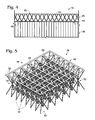
- Fig. 4 illustrates a portion of an illustrative, non-exclusive example of a ventilated aero-structure 16 that includes a skin 44 operatively coupled to the second side 42 of the micro-lattice structure 26 and a honeycomb core 28 operatively coupled to the first side 40 of the micro-lattice structure 26.
- the illustrated ventilated aero-structure 16 of Fig. 4 includes an adherence structure 46 on the first side 40 of the micro-lattice structure 26.
- Fig. 5 illustrates a portion of an illustrative, non-exclusive example of a micro-lattice structure 26 and an illustrative, non-exclusive example of an adherence structure 46 formed on the first side 40 of the micro-lattice structure 26.
- the illustrated example of micro-lattice structure 26 includes trusses 30 that intersect to define first-side nodes 50 and second-side nodes 52.
- the illustrated example of adherence structure 46 includes an adherence surface 48 that defines a grid 56 interconnecting the first-side nodes 50.
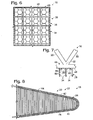
- Fig. 6 schematically illustrates in profile the interface between an adherence surface 48 in the form of a grid 56 and a honeycomb core 28 having hexagonal cells 36.
- a node 32 of a micro-lattice structure 26 coincides with each intersection of the grid 56
- a total of 65 points of contact between the adherence surface 48 and the walls 34 of the schematically represented honeycomb core 28 are present and may be utilized for adhering the adherence structure 46 to the honeycomb core 28.
- the adherence structure 46 were not present, only approximately 25 nodes 32 would coincide with and contact a wall 34 of the honeycomb structure 28.
- a resulting ventilated aero-structure 16 would include approximately 7200 points of contact per square foot (0.09 square meter) between the adherence surface 48 and the walls 34 of the honeycomb core 28.
- Fig. 7 illustrates in side profile the interface between an adherence structure 46 and honeycomb core 28. As illustrated, the adhesive 58 forms fillets 60 between the adherence surface 48 and the walls 34 of the honeycomb core 28.
- Fig. 8 illustrates an illustrative, non-exclusive example of a ventilated aero-structure 16 that defines a leading edge 20 of an airfoil 22.
- the example ventilated aero-structure 16 of Fig. 8 includes a honeycomb core 28 operatively coupled to the first side 40 of the micro-lattice structure 26 and a skin 44 operatively coupled to the second side 42 of the micro-lattice structure 26.
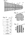
- Fig. 9 illustrates another illustrative, non-exclusive example of a ventilated aero-structure 16 that defines a leading edge 20 of an airfoil 22.
- the example ventilated aero-structure 16 of Fig. 9 includes a micro-lattice structure 26 that extends within a honeycomb core 28, with the honeycomb core 28 being operatively coupled to the first side 40 and the second side 42 of the micro-lattice structure 26.
- the skin 44 is operatively coupled to the honeycomb core 28 and is not coupled directly to the micro-lattice structure 26.
- Fig. 10 schematically provides a flowchart that represents illustrative, non-exclusive examples of methods according to the present disclosure.
- some steps are illustrated in dashed boxes indicating that such steps may be optional or may correspond to an optional version of a method according to the present disclosure. That said, not all methods according to the present disclosure are required to include the steps illustrated in solid boxes.
- the methods and steps illustrated in Fig. 10 are not limiting and other methods and steps are within the scope of the present disclosure, including methods having greater than or fewer than the number of steps illustrated, as understood from the discussions herein.
- Fig. 10 schematically represents illustrative, non-exclusive examples of methods 100 of constructing a ventilated aero-structure 16.
- a method 100 may include at least the step of operatively coupling a micro-lattice structure 26 to a honeycomb core 28, as indicated at 102.
- coupling 102 also may include operatively coupling a skin 44 to the second side 42 of the micro-lattice structure 26.
- an adherence structure 46 may be bonded to the micro-lattice structure 26, as indicated at 104.
- the micro-lattice structure 26 and the adherence structure 46 may be formed into a predetermined shape, as indicated at 106.
- the micro-lattice structure 26 and the adherence structure 46 may be formed into a shape that corresponds to a section of an airframe 12 of an aircraft 10.
- the micro-lattice structure 26 and adherence structure 46 may be formed into a shape corresponding to a leading edge 20 of an airfoil 22.
- Shapes corresponding to other portions or sections of an aircraft 10 also are within the scope of the present disclosure, including (but not limited to) trailing edges 21 of airfoils 22, other portions of airfoils 22, the nose 24, portions of the fuselage of the aircraft 10, portions of vertical stabilizers 23, etc.
- the micro-lattice structure 26 and the adherence structure 46 may be described as being net-shaped to conform to the curvature of a mating part, by thermal post-curing while in contact with a mold in a predetermined shape.
- the bonding 104 may include a step of placing the micro-lattice structure 26 into a volume, or bath, of UV-curable monomer and adjacent to a mask that is configured to define a predetermined configuration of the adherence structure 46, as indicated at 108. After the placing 108, the UV-curable monomer may be cured to form the adherence structure 46 on the micro-lattice structure 26, as indicated at 110.
- the UV light may be emitted from a 2,000 Watt mercury arc lamp for 1-10 seconds.
- Figs. 11-12 schematically represent illustrative, non-exclusive examples of suitable masks 112 that may be used during the bonding 104 of an adherence structure 46 to a micro-lattice structure 26.
- the regular two-dimensional pattern of squares 114 represent portions of a mask 112, through which ultraviolet (UV) light will not penetrate.
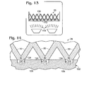
- UV light 118 when the UV-curable monomer 116 is exposed to UV light 118, as schematically illustrated in Fig. 13 , the UV light 118 will cure the portions of the UV-curable monomer 116 that are not blocked by the squares, resulting in an adherence structure 46 and adherence surface 48 that defines a grid 56.
- a solvent such as in a toluene bath. Any residual solvent may be removed with heat, such as in an 85 degree Celsius oven for approximately two hours.
- the regular two-dimensional pattern of elongate strips 120 represent portions of a mask 112, through which UV light will not penetrate. Accordingly, when the UV-curable monomer 116 is exposed to UV light 118, the UV light 118 will cure the portions of the UV-curable monomer 116 that are not blocked by the strips, resulting in an adherence structure 46 and an adherence surface 48 that defines a plurality of spaced-apart elongate strips. The UV-curable monomer 116 that was not exposed to the UV light 118 and thus that was not cured, then may be rinsed away as discussed above.
- micro-lattice structure 26 When utilizing an embodiment of micro-lattice structure 26 that includes first-side nodes 50 and/or second-side nodes 52 and when utilizing the mask 112 of Fig. 11 to create a grid 56, during the placing 108, the first-nodes 50 or the second-side nodes 52 may be aligned between four adjacent corners of the squares 114, so that the adherence structure 46 will interconnect the first-side nodes 50 or second-side nodes 52. Similarly, when utilizing an embodiment of micro-lattice structure 26 that includes first-side nodes 50 and/or second-side nodes 52 and when utilizing the mask 112 of Fig.
- the first-nodes 50 or the second-side nodes 52 may be aligned to coincide between the elongate strips 120 of the mask 112, so that the adherence structure 46 will interconnect linear series of first-side nodes 50 or second-side nodes 52.
- masks 112 are within the scope of the present disclosure and may be used in connection with an optional bonding step 104 of a method 100.
- the bonding 104 may additionally or alternatively include a step of placing the micro-lattice structure 26 on top of a mold 122, with the mold 122 defining a series of channels 124.
- the series of channels 124 may define a grid, a series of spaced-apart elongate channels, or any other suitable configuration corresponding to a desired configuration of adherence structure 46. Accordingly, the first-side nodes 50 of the micro-lattice structure 26 may be appropriately aligned with the channels 124 during the bonding 104.
- the series of channels 124 may be filed with a volume of UV-curable monomer 116, which may be cured during the curing step 110, such as by utilizing UV light.
- one or more channels 124 may include one or more bores 126 extending from the channels 124, with the bores 126 being configured to form optional spaced-apart projections 54.
- Fig. 10 also schematically represents illustrative, non-exclusive examples of methods 200 of assembling an aircraft 10.
- Methods 200 may include a method 100, and after a method 100, a method 200 may further include assembling the aircraft 10 utilizing a ventilated aero-structure 16, as indicated at 202.
- the apparatuses and methods disclosed herein may find application outside of aircraft, including (but not limited to) boat hulls, antennas, spacecraft, satellites, and any other apparatuses that include energy absorbing structures, such as that typically include honeycomb core structures. Accordingly, where applicable, the term “structure 16" may be used in place of the term “ventilated aero-structure 16" herein.
- the term “configured” means that the element, component, or other subject matter is designed and/or intended to perform a given function. Thus, the use of the term “configured” should not be construed to mean that a given element, component, or other subject matter is simply “capable of” performing a given function but that the element, component, and/or other subject matter is specifically selected, created, implemented, utilized, programmed, and/or designed for the purpose of performing the function. It is also within the scope of the present disclosure that elements, components, and/or other recited subject matter that is recited as being configured to perform a particular function may additionally or alternatively be described as being adapted to perform that function.
Landscapes
- Engineering & Computer Science (AREA)
- Mechanical Engineering (AREA)
- Aviation & Aerospace Engineering (AREA)
- Laminated Bodies (AREA)
- Motor Or Generator Cooling System (AREA)
- Linear Motors (AREA)
- Iron Core Of Rotating Electric Machines (AREA)
Claims (15)
- Aérostructure ventilée, comprenant :une structure en micro-treillis comportant un premier côté et un deuxième côté, dans laquelle la structure en micro-treillis comprend une pluralité d'éléments de treillis, et dans laquelle la pluralité d'éléments de treillis définissent une pluralité de noeuds aux intersections de deux éléments de treillis ou plus ; etun coeur en nid d'abeilles accouplé fonctionnellement au premier côté de la structure en micro-treillis, dans laquelle le coeur en nid d'abeilles comprend une pluralité de parois qui définissent une pluralité de cellules allongées ;dans laquelle une interface entre le coeur en nid d'abeilles et la structure en micro-treillis est configurée pour permettre la circulation d'air vers et à partir du coeur en nid d'abeilles par l'intermédiaire de la structure en micro-treillis.
- Aérostructure ventilée selon la revendication 1, comprenant en outre :une structure d'adhérence formée sur le premier côté de la structure en micro-treillis, dans laquelle la structure d'adhérence définit une surface d'adhérence qui adhère au coeur en nid d'abeilles.
- Aérostructure ventilée selon la revendication 2,
dans laquelle un sous-ensemble de la pluralité de noeuds coïncident avec le premier côté de la structure en micro-treillis et définissent une pluralité de noeuds de premier côté ; et
dans laquelle la structure d'adhérence relie entre eux au moins un sous-ensemble de la pluralité de noeuds de premier côté. - Aérostructure ventilée selon la revendication 3,
dans laquelle la surface d'adhérence définit l'une d'une grille, ou d'une pluralité de bandes allongées espacées. - Aérostructure ventilée selon la revendication 3,
dans laquelle la surface d'adhérence est définie par une pluralité de surfaces espacées, dans laquelle chacune de la pluralité de surfaces espacées relie entre eux un sous-ensemble de la pluralité de noeuds de premier côté. - Aérostructure ventilée selon la revendication 2,
dans laquelle la structure d'adhérence est composée d'un polymère formé à partir d'un monomère durcissable sous UV. - Aérostructure ventilée selon la revendication 2, comprenant en outre :une peau accouplée fonctionnellement au deuxième côté de la structure en micro-treillis.
- Aérostructure ventilée selon la revendication 2,
dans laquelle le coeur en nid d'abeilles est en outre accouplé fonctionnellement au deuxième côté de la structure en micro-treillis ;
dans laquelle la structure d'adhérence est une première structure d'adhérence et la surface d'adhérence est une première surface d'adhérence ; et
dans laquelle l'aérostructure ventilée comprend en outre :une deuxième structure d'adhérence formée sur le deuxième côté de la structure en micro-treillis, dans laquelle la deuxième structure d'adhérence définit une deuxième surface d'adhérence sur le deuxième côté qui adhère au coeur en nid d'abeilles. - Aérostructure ventilée selon la revendication 8,
dans laquelle un deuxième sous-ensemble de la pluralité de noeuds coïncident avec le deuxième côté de la structure en micro-treillis et définissent une pluralité de noeuds de deuxième côté ;
dans laquelle la deuxième structure d'adhérence relie entre eux au moins un sous-ensemble de la pluralité de noeuds de deuxième côté ; et
dans laquelle la deuxième surface d'adhérence définit l'une d'une grille, ou d'une pluralité de bandes allongées espacées. - Aérostructure ventilée selon la revendication 9,
dans laquelle la deuxième surface d'adhérence est définie par une pluralité de surfaces de deuxième côté espacées, dans laquelle chacune de la pluralité de surfaces de deuxième côté espacée relie entre eux un sous-ensemble de la pluralité de noeuds de deuxième côté. - Aérostructure ventilée selon la revendication 8,
dans laquelle la deuxième structure d'adhérence est composée d'un polymère formé à partir d'un monomère durcissable sous UV. - Aérostructure ventilée selon l'une quelconque des revendications précédentes, comprenant en outre :une pluralité de protubérances espacées s'étendant de la structure en micro-treillis dans au moins un sous-ensemble de cellules allongées du coeur en nid d'abeilles.
- Procédé de construction d'une aérostructure ventilée, le procédé comprenant :l'accouplement d'une structure en micro-treillis à un coeur en nid d'abeilles pour définir une partie d'une cellule d'un avion.
- Procédé selon la revendication 13, comprenant en outre :avant l'accouplement, la liaison d'une structure d'adhérence à un premier côté d'une structure en micro-treillis;dans lequel l'accouplement comprend l'adhérence de la structure d'adhérence au coeur en nid d'abeilles.
- Procédé selon la revendication 13, comprenant en outre :après la liaison et avant l'accouplement, la formation de la structure en micro-treillis et de la structure d'adhérence en une forme prédéterminée correspondant à une section d'une cellule.
Applications Claiming Priority (1)
| Application Number | Priority Date | Filing Date | Title |
|---|---|---|---|
| US13/469,913 US9321241B2 (en) | 2012-05-11 | 2012-05-11 | Ventilated aero-structures, aircraft and associated methods |
Publications (2)
| Publication Number | Publication Date |
|---|---|
| EP2662207A1 EP2662207A1 (fr) | 2013-11-13 |
| EP2662207B1 true EP2662207B1 (fr) | 2015-01-28 |
Family
ID=48482904
Family Applications (1)
| Application Number | Title | Priority Date | Filing Date |
|---|---|---|---|
| EP13167336.0A Active EP2662207B1 (fr) | 2012-05-11 | 2013-05-10 | Aéro-structures ventilées, aéronef et procédés associés |
Country Status (3)
| Country | Link |
|---|---|
| US (2) | US9321241B2 (fr) |
| EP (1) | EP2662207B1 (fr) |
| ES (1) | ES2531154T3 (fr) |
Families Citing this family (18)
| Publication number | Priority date | Publication date | Assignee | Title |
|---|---|---|---|---|
| US10556670B2 (en) * | 2010-08-15 | 2020-02-11 | The Boeing Company | Laminar flow panel |
| US9771998B1 (en) | 2014-02-13 | 2017-09-26 | Hrl Laboratories, Llc | Hierarchical branched micro-truss structure and methods of manufacturing the same |
| CN103887605B (zh) * | 2014-04-04 | 2016-08-24 | 西安电子科技大学 | 结构功能一体化机翼天线 |
| US9733429B2 (en) | 2014-08-18 | 2017-08-15 | Hrl Laboratories, Llc | Stacked microlattice materials and fabrication processes |
| US9162416B1 (en) * | 2014-08-18 | 2015-10-20 | Hrl Laboratories, Llc | Basal plane reinforced microlattice |
| US9783324B2 (en) * | 2014-08-26 | 2017-10-10 | The Boeing Company | Vessel insulation assembly |
| US10427336B2 (en) | 2014-11-20 | 2019-10-01 | Baker Hughes, A Ge Company, Llc | Periodic structured composite and articles therefrom |
| US10358821B2 (en) * | 2015-03-02 | 2019-07-23 | The Boeing Company | Thermoplastic truss structure for use in wing and rotor blade structures and methods for manufacture |
| CA2949257C (fr) * | 2016-02-12 | 2020-12-22 | The Boeing Company | Panneau d'ecoulement laminaire |
| US10179428B2 (en) * | 2016-11-17 | 2019-01-15 | The Boeing Company | Mechanically reinforced foam insulation panel and methods of making the same |
| US10479520B2 (en) * | 2017-05-25 | 2019-11-19 | The Boeing Company | Composite structure assembly having an interconnected layered core |
| US10203169B2 (en) * | 2017-06-12 | 2019-02-12 | Microsoft Technology Licensing, Llc | Thermal management devices, systems and methods |
| DE102017128497A1 (de) * | 2017-11-30 | 2019-06-06 | Airbus Operations Gmbh | Vorderkantenanordnung für einen Strömungskörper eines Fahrzeugs |
| US11034460B2 (en) * | 2017-12-08 | 2021-06-15 | The Boeing Company | Additively manufactured septa for acoustic panels |
| EP3539865A1 (fr) | 2018-03-12 | 2019-09-18 | Ge Avio S.r.l. | Ensemble de support de pale de rotor ou d'helice |
| US11577815B2 (en) * | 2020-01-30 | 2023-02-14 | Textron Innovations Inc. | Isogrid patterns for structural aircraft panels |
| US12172415B2 (en) | 2023-01-12 | 2024-12-24 | The Boeing Company | Sandwich panels and methods of manufacturing sandwich panels |
| EP4724340A1 (fr) * | 2023-06-12 | 2026-04-15 | EnerKite GmbH | Structures de chambres creuses aérodynamiques |
Family Cites Families (18)
| Publication number | Priority date | Publication date | Assignee | Title |
|---|---|---|---|---|
| US3261576A (en) * | 1962-06-14 | 1966-07-19 | Olin Mathieson | Aircraft structure |
| US4749150A (en) * | 1985-12-24 | 1988-06-07 | Rohr Industries, Inc. | Turbofan duct with noise suppression and boundary layer control |
| US4671841A (en) * | 1986-01-06 | 1987-06-09 | Rohr Industries, Inc. | Method of making an acoustic panel with a triaxial open-weave face sheet |
| DE3720371A1 (de) * | 1987-06-19 | 1989-01-05 | Messerschmitt Boelkow Blohm | Leichtbauverbundplatte und verfahren zu deren herstellung |
| US4990391A (en) * | 1989-02-03 | 1991-02-05 | Rohr Industries, Inc. | Reticulated core to perforate sheet bonding and galvanic barrier |
| US5721402A (en) * | 1996-09-09 | 1998-02-24 | Northrop Grumman Corporation | Noise suppression system for a jet engine |
| DE19804718C2 (de) * | 1998-02-06 | 2001-09-13 | Eurocopter Deutschland | Schall absorbierende Sandwichwand |
| DE10154063B4 (de) * | 2001-11-02 | 2013-11-28 | Airbus Operations Gmbh | Doppelwandiger Kernverbund, vorzugsweise Faserverbund |
| US20060080835A1 (en) * | 2003-02-14 | 2006-04-20 | Kooistra Gregory W | Methods for manufacture of multilayered multifunctional truss structures and related structures there from |
| US7382959B1 (en) | 2006-10-13 | 2008-06-03 | Hrl Laboratories, Llc | Optically oriented three-dimensional polymer microstructures |
| US8191616B2 (en) * | 2006-11-02 | 2012-06-05 | The Boeing Company | Combined thermal protection and surface temperature control system |
| US8096508B2 (en) * | 2007-08-10 | 2012-01-17 | 3M Innovative Properties Company | Erosion resistant films for use on heated aerodynamic surfaces |
| US8079443B2 (en) * | 2008-01-07 | 2011-12-20 | Pelzer Acoustic Products Gmbh | Aircraft trim panel with integrated adjustable acoustic properties |
| US8052089B2 (en) | 2008-11-03 | 2011-11-08 | The Boeing Company | Anti-icing apparatus for honeycomb structures |
| DE102008062701A1 (de) * | 2008-12-17 | 2010-07-01 | Airbus Deutschland Gmbh | Flugzeugkabinenpaneel mit Kerntaschen zur Schallabsorption |
| US8092957B2 (en) | 2009-05-15 | 2012-01-10 | GM Global Technology Operations LLC | Diffusion media formed by photopolymer based processes |
| US8800641B2 (en) | 2009-06-01 | 2014-08-12 | The Boeing Company | Methods and apparatus for a micro-truss based structural insulation layer |
| DE102010015638B4 (de) | 2010-04-20 | 2015-02-12 | Airbus Operations Gmbh | Luftfahrzeugkabinen-Plattenabsorber |
-
2012
- 2012-05-11 US US13/469,913 patent/US9321241B2/en active Active
-
2013
- 2013-05-10 ES ES13167336T patent/ES2531154T3/es active Active
- 2013-05-10 EP EP13167336.0A patent/EP2662207B1/fr active Active
-
2016
- 2016-03-16 US US15/072,088 patent/US10183736B2/en active Active
Also Published As
| Publication number | Publication date |
|---|---|
| US20160194070A1 (en) | 2016-07-07 |
| EP2662207A1 (fr) | 2013-11-13 |
| US20130303067A1 (en) | 2013-11-14 |
| US9321241B2 (en) | 2016-04-26 |
| ES2531154T3 (es) | 2015-03-11 |
| US10183736B2 (en) | 2019-01-22 |
Similar Documents
| Publication | Publication Date | Title |
|---|---|---|
| EP2662207B1 (fr) | Aéro-structures ventilées, aéronef et procédés associés | |
| JP7086574B2 (ja) | ハニカム状構造を備えた部品を含む構成要素 | |
| CN104669728B (zh) | 具有加强芯部的复合结构及其制造方法 | |
| US9638048B2 (en) | Systems and methods of constructing composite assemblies | |
| EP2130762B1 (fr) | Aile et structure de surface portante d'empennage fabriquées en matériau thermoplastique doté d'une configuration à double enveloppe durcie | |
| JP7144174B2 (ja) | 高度に積載された一次および二次構造部品の修理のための構造的な予備硬化修理パッチ | |
| AU2016266006A1 (en) | Stacked noodle for high capacity pull-off for a composite stringer | |
| US9469390B2 (en) | Monolithic acoustically-treated composite structures and methods for fabricating the same | |
| CA2207403A1 (fr) | Longeron en forme de feuilles ondulees a amplitude reduite | |
| US11541982B2 (en) | Stiffened structural component for an aircraft | |
| CA3077836C (fr) | Panneaux de fuselage en sandwich sans tamis | |
| US20210237846A1 (en) | Wing structure | |
| US11511847B2 (en) | Skin panel of composite material having an internal grid | |
| ES2415773B1 (es) | Método de fabricación de piezas de material compuesto con cambios de espesor | |
| KR102745301B1 (ko) | 심재 및 구조체 | |
| CA3011019A1 (fr) | Outil de moule ayant des proprietes thermiques anisotropes | |
| US10220593B2 (en) | Composite material incorporating water ingress barrier | |
| US10654208B2 (en) | Assembly fixture with anisotropic thermal properties | |
| US10550499B2 (en) | Fabricating composite core with woven composite fibers | |
| Gramüller et al. | Design process and manufacturing of an unmanned blended wing-body aircraft | |
| US12384511B2 (en) | Composite core structures for aircraft | |
| US12275525B2 (en) | Net edge composite core splices for aircraft wing | |
| US10442520B1 (en) | Enhanced wing efficiency via differential thermal coefficient of expansion spar caps | |
| WO2018055647A1 (fr) | Procédé de fabrication de structures de matériau composite intégré à l'aide d'un appareil modulaire | |
| Petrova et al. | Properties of joints based on honeycomb structures made using adhesive prepregs |
Legal Events
| Date | Code | Title | Description |
|---|---|---|---|
| PUAI | Public reference made under article 153(3) epc to a published international application that has entered the european phase |
Free format text: ORIGINAL CODE: 0009012 |
|
| 17P | Request for examination filed |
Effective date: 20130510 |
|
| AK | Designated contracting states |
Kind code of ref document: A1 Designated state(s): AL AT BE BG CH CY CZ DE DK EE ES FI FR GB GR HR HU IE IS IT LI LT LU LV MC MK MT NL NO PL PT RO RS SE SI SK SM TR |
|
| AX | Request for extension of the european patent |
Extension state: BA ME |
|
| GRAP | Despatch of communication of intention to grant a patent |
Free format text: ORIGINAL CODE: EPIDOSNIGR1 |
|
| INTG | Intention to grant announced |
Effective date: 20140808 |
|
| GRAS | Grant fee paid |
Free format text: ORIGINAL CODE: EPIDOSNIGR3 |
|
| GRAA | (expected) grant |
Free format text: ORIGINAL CODE: 0009210 |
|
| AK | Designated contracting states |
Kind code of ref document: B1 Designated state(s): AL AT BE BG CH CY CZ DE DK EE ES FI FR GB GR HR HU IE IS IT LI LT LU LV MC MK MT NL NO PL PT RO RS SE SI SK SM TR |
|
| REG | Reference to a national code |
Ref country code: GB Ref legal event code: FG4D |
|
| REG | Reference to a national code |
Ref country code: CH Ref legal event code: EP |
|
| REG | Reference to a national code |
Ref country code: IE Ref legal event code: FG4D |
|
| REG | Reference to a national code |
Ref country code: ES Ref legal event code: FG2A Ref document number: 2531154 Country of ref document: ES Kind code of ref document: T3 Effective date: 20150311 |
|
| REG | Reference to a national code |
Ref country code: AT Ref legal event code: REF Ref document number: 708051 Country of ref document: AT Kind code of ref document: T Effective date: 20150315 |
|
| REG | Reference to a national code |
Ref country code: DE Ref legal event code: R096 Ref document number: 602013000917 Country of ref document: DE Effective date: 20150319 |
|
| REG | Reference to a national code |
Ref country code: AT Ref legal event code: MK05 Ref document number: 708051 Country of ref document: AT Kind code of ref document: T Effective date: 20150128 |
|
| REG | Reference to a national code |
Ref country code: NL Ref legal event code: VDEP Effective date: 20150128 |
|
| REG | Reference to a national code |
Ref country code: LT Ref legal event code: MG4D |
|
| PG25 | Lapsed in a contracting state [announced via postgrant information from national office to epo] |
Ref country code: LT Free format text: LAPSE BECAUSE OF FAILURE TO SUBMIT A TRANSLATION OF THE DESCRIPTION OR TO PAY THE FEE WITHIN THE PRESCRIBED TIME-LIMIT Effective date: 20150128 Ref country code: HR Free format text: LAPSE BECAUSE OF FAILURE TO SUBMIT A TRANSLATION OF THE DESCRIPTION OR TO PAY THE FEE WITHIN THE PRESCRIBED TIME-LIMIT Effective date: 20150128 Ref country code: SE Free format text: LAPSE BECAUSE OF FAILURE TO SUBMIT A TRANSLATION OF THE DESCRIPTION OR TO PAY THE FEE WITHIN THE PRESCRIBED TIME-LIMIT Effective date: 20150128 Ref country code: FI Free format text: LAPSE BECAUSE OF FAILURE TO SUBMIT A TRANSLATION OF THE DESCRIPTION OR TO PAY THE FEE WITHIN THE PRESCRIBED TIME-LIMIT Effective date: 20150128 Ref country code: NO Free format text: LAPSE BECAUSE OF FAILURE TO SUBMIT A TRANSLATION OF THE DESCRIPTION OR TO PAY THE FEE WITHIN THE PRESCRIBED TIME-LIMIT Effective date: 20150428 Ref country code: BG Free format text: LAPSE BECAUSE OF FAILURE TO SUBMIT A TRANSLATION OF THE DESCRIPTION OR TO PAY THE FEE WITHIN THE PRESCRIBED TIME-LIMIT Effective date: 20150428 |
|
| PG25 | Lapsed in a contracting state [announced via postgrant information from national office to epo] |
Ref country code: AT Free format text: LAPSE BECAUSE OF FAILURE TO SUBMIT A TRANSLATION OF THE DESCRIPTION OR TO PAY THE FEE WITHIN THE PRESCRIBED TIME-LIMIT Effective date: 20150128 Ref country code: LV Free format text: LAPSE BECAUSE OF FAILURE TO SUBMIT A TRANSLATION OF THE DESCRIPTION OR TO PAY THE FEE WITHIN THE PRESCRIBED TIME-LIMIT Effective date: 20150128 Ref country code: RS Free format text: LAPSE BECAUSE OF FAILURE TO SUBMIT A TRANSLATION OF THE DESCRIPTION OR TO PAY THE FEE WITHIN THE PRESCRIBED TIME-LIMIT Effective date: 20150128 Ref country code: NL Free format text: LAPSE BECAUSE OF FAILURE TO SUBMIT A TRANSLATION OF THE DESCRIPTION OR TO PAY THE FEE WITHIN THE PRESCRIBED TIME-LIMIT Effective date: 20150128 Ref country code: IS Free format text: LAPSE BECAUSE OF FAILURE TO SUBMIT A TRANSLATION OF THE DESCRIPTION OR TO PAY THE FEE WITHIN THE PRESCRIBED TIME-LIMIT Effective date: 20150528 Ref country code: PL Free format text: LAPSE BECAUSE OF FAILURE TO SUBMIT A TRANSLATION OF THE DESCRIPTION OR TO PAY THE FEE WITHIN THE PRESCRIBED TIME-LIMIT Effective date: 20150128 Ref country code: GR Free format text: LAPSE BECAUSE OF FAILURE TO SUBMIT A TRANSLATION OF THE DESCRIPTION OR TO PAY THE FEE WITHIN THE PRESCRIBED TIME-LIMIT Effective date: 20150429 |
|
| REG | Reference to a national code |
Ref country code: DE Ref legal event code: R097 Ref document number: 602013000917 Country of ref document: DE |
|
| PG25 | Lapsed in a contracting state [announced via postgrant information from national office to epo] |
Ref country code: SK Free format text: LAPSE BECAUSE OF FAILURE TO SUBMIT A TRANSLATION OF THE DESCRIPTION OR TO PAY THE FEE WITHIN THE PRESCRIBED TIME-LIMIT Effective date: 20150128 Ref country code: DK Free format text: LAPSE BECAUSE OF FAILURE TO SUBMIT A TRANSLATION OF THE DESCRIPTION OR TO PAY THE FEE WITHIN THE PRESCRIBED TIME-LIMIT Effective date: 20150128 Ref country code: EE Free format text: LAPSE BECAUSE OF FAILURE TO SUBMIT A TRANSLATION OF THE DESCRIPTION OR TO PAY THE FEE WITHIN THE PRESCRIBED TIME-LIMIT Effective date: 20150128 Ref country code: RO Free format text: LAPSE BECAUSE OF FAILURE TO SUBMIT A TRANSLATION OF THE DESCRIPTION OR TO PAY THE FEE WITHIN THE PRESCRIBED TIME-LIMIT Effective date: 20150128 Ref country code: CZ Free format text: LAPSE BECAUSE OF FAILURE TO SUBMIT A TRANSLATION OF THE DESCRIPTION OR TO PAY THE FEE WITHIN THE PRESCRIBED TIME-LIMIT Effective date: 20150128 |
|
| PLBE | No opposition filed within time limit |
Free format text: ORIGINAL CODE: 0009261 |
|
| STAA | Information on the status of an ep patent application or granted ep patent |
Free format text: STATUS: NO OPPOSITION FILED WITHIN TIME LIMIT |
|
| PG25 | Lapsed in a contracting state [announced via postgrant information from national office to epo] |
Ref country code: IT Free format text: LAPSE BECAUSE OF FAILURE TO SUBMIT A TRANSLATION OF THE DESCRIPTION OR TO PAY THE FEE WITHIN THE PRESCRIBED TIME-LIMIT Effective date: 20150128 |
|
| 26N | No opposition filed |
Effective date: 20151029 |
|
| PG25 | Lapsed in a contracting state [announced via postgrant information from national office to epo] |
Ref country code: LU Free format text: LAPSE BECAUSE OF FAILURE TO SUBMIT A TRANSLATION OF THE DESCRIPTION OR TO PAY THE FEE WITHIN THE PRESCRIBED TIME-LIMIT Effective date: 20150510 Ref country code: MC Free format text: LAPSE BECAUSE OF FAILURE TO SUBMIT A TRANSLATION OF THE DESCRIPTION OR TO PAY THE FEE WITHIN THE PRESCRIBED TIME-LIMIT Effective date: 20150128 |
|
| REG | Reference to a national code |
Ref country code: IE Ref legal event code: MM4A |
|
| PG25 | Lapsed in a contracting state [announced via postgrant information from national office to epo] |
Ref country code: SI Free format text: LAPSE BECAUSE OF FAILURE TO SUBMIT A TRANSLATION OF THE DESCRIPTION OR TO PAY THE FEE WITHIN THE PRESCRIBED TIME-LIMIT Effective date: 20150128 |
|
| PG25 | Lapsed in a contracting state [announced via postgrant information from national office to epo] |
Ref country code: IE Free format text: LAPSE BECAUSE OF NON-PAYMENT OF DUE FEES Effective date: 20150510 |
|
| REG | Reference to a national code |
Ref country code: FR Ref legal event code: PLFP Year of fee payment: 4 |
|
| PG25 | Lapsed in a contracting state [announced via postgrant information from national office to epo] |
Ref country code: BE Free format text: LAPSE BECAUSE OF FAILURE TO SUBMIT A TRANSLATION OF THE DESCRIPTION OR TO PAY THE FEE WITHIN THE PRESCRIBED TIME-LIMIT Effective date: 20150128 |
|
| PG25 | Lapsed in a contracting state [announced via postgrant information from national office to epo] |
Ref country code: MT Free format text: LAPSE BECAUSE OF FAILURE TO SUBMIT A TRANSLATION OF THE DESCRIPTION OR TO PAY THE FEE WITHIN THE PRESCRIBED TIME-LIMIT Effective date: 20150128 |
|
| REG | Reference to a national code |
Ref country code: CH Ref legal event code: PL |
|
| PG25 | Lapsed in a contracting state [announced via postgrant information from national office to epo] |
Ref country code: CH Free format text: LAPSE BECAUSE OF NON-PAYMENT OF DUE FEES Effective date: 20160531 Ref country code: LI Free format text: LAPSE BECAUSE OF NON-PAYMENT OF DUE FEES Effective date: 20160531 |
|
| REG | Reference to a national code |
Ref country code: FR Ref legal event code: PLFP Year of fee payment: 5 |
|
| PG25 | Lapsed in a contracting state [announced via postgrant information from national office to epo] |
Ref country code: HU Free format text: LAPSE BECAUSE OF FAILURE TO SUBMIT A TRANSLATION OF THE DESCRIPTION OR TO PAY THE FEE WITHIN THE PRESCRIBED TIME-LIMIT; INVALID AB INITIO Effective date: 20130510 |
|
| PG25 | Lapsed in a contracting state [announced via postgrant information from national office to epo] |
Ref country code: CY Free format text: LAPSE BECAUSE OF FAILURE TO SUBMIT A TRANSLATION OF THE DESCRIPTION OR TO PAY THE FEE WITHIN THE PRESCRIBED TIME-LIMIT Effective date: 20150128 |
|
| PG25 | Lapsed in a contracting state [announced via postgrant information from national office to epo] |
Ref country code: TR Free format text: LAPSE BECAUSE OF FAILURE TO SUBMIT A TRANSLATION OF THE DESCRIPTION OR TO PAY THE FEE WITHIN THE PRESCRIBED TIME-LIMIT Effective date: 20150128 |
|
| REG | Reference to a national code |
Ref country code: FR Ref legal event code: PLFP Year of fee payment: 6 |
|
| PG25 | Lapsed in a contracting state [announced via postgrant information from national office to epo] |
Ref country code: SM Free format text: LAPSE BECAUSE OF FAILURE TO SUBMIT A TRANSLATION OF THE DESCRIPTION OR TO PAY THE FEE WITHIN THE PRESCRIBED TIME-LIMIT Effective date: 20150128 |
|
| PG25 | Lapsed in a contracting state [announced via postgrant information from national office to epo] |
Ref country code: PT Free format text: LAPSE BECAUSE OF FAILURE TO SUBMIT A TRANSLATION OF THE DESCRIPTION OR TO PAY THE FEE WITHIN THE PRESCRIBED TIME-LIMIT Effective date: 20150128 Ref country code: MK Free format text: LAPSE BECAUSE OF FAILURE TO SUBMIT A TRANSLATION OF THE DESCRIPTION OR TO PAY THE FEE WITHIN THE PRESCRIBED TIME-LIMIT Effective date: 20150128 |
|
| PG25 | Lapsed in a contracting state [announced via postgrant information from national office to epo] |
Ref country code: AL Free format text: LAPSE BECAUSE OF FAILURE TO SUBMIT A TRANSLATION OF THE DESCRIPTION OR TO PAY THE FEE WITHIN THE PRESCRIBED TIME-LIMIT Effective date: 20150128 |
|
| P01 | Opt-out of the competence of the unified patent court (upc) registered |
Effective date: 20230516 |
|
| PGFP | Annual fee paid to national office [announced via postgrant information from national office to epo] |
Ref country code: DE Payment date: 20250529 Year of fee payment: 13 |
|
| PGFP | Annual fee paid to national office [announced via postgrant information from national office to epo] |
Ref country code: GB Payment date: 20250527 Year of fee payment: 13 Ref country code: ES Payment date: 20250602 Year of fee payment: 13 |
|
| PGFP | Annual fee paid to national office [announced via postgrant information from national office to epo] |
Ref country code: FR Payment date: 20250526 Year of fee payment: 13 |