EP2662338A2 - Système d'épuration d'eaux contaminées et procédé d'épuration - Google Patents
Système d'épuration d'eaux contaminées et procédé d'épuration Download PDFInfo
- Publication number
- EP2662338A2 EP2662338A2 EP12738147.3A EP12738147A EP2662338A2 EP 2662338 A2 EP2662338 A2 EP 2662338A2 EP 12738147 A EP12738147 A EP 12738147A EP 2662338 A2 EP2662338 A2 EP 2662338A2
- Authority
- EP
- European Patent Office
- Prior art keywords
- water
- main
- deposit
- polluted water
- deposits
- Prior art date
- Legal status (The legal status is an assumption and is not a legal conclusion. Google has not performed a legal analysis and makes no representation as to the accuracy of the status listed.)
- Granted
Links
Images




Classifications
-
- C—CHEMISTRY; METALLURGY
- C02—TREATMENT OF WATER, WASTE WATER, SEWAGE, OR SLUDGE
- C02F—TREATMENT OF WATER, WASTE WATER, SEWAGE, OR SLUDGE
- C02F1/00—Treatment of water, waste water, or sewage
- C02F1/52—Treatment of water, waste water, or sewage by flocculation or precipitation of suspended impurities
-
- B—PERFORMING OPERATIONS; TRANSPORTING
- B01—PHYSICAL OR CHEMICAL PROCESSES OR APPARATUS IN GENERAL
- B01D—SEPARATION
- B01D21/00—Separation of suspended solid particles from liquids by sedimentation
- B01D21/0012—Settling tanks making use of filters, e.g. by floating layers of particulate material
-
- B—PERFORMING OPERATIONS; TRANSPORTING
- B01—PHYSICAL OR CHEMICAL PROCESSES OR APPARATUS IN GENERAL
- B01D—SEPARATION
- B01D21/00—Separation of suspended solid particles from liquids by sedimentation
- B01D21/0018—Separation of suspended solid particles from liquids by sedimentation provided with a pump mounted in or on a settling tank
-
- B—PERFORMING OPERATIONS; TRANSPORTING
- B01—PHYSICAL OR CHEMICAL PROCESSES OR APPARATUS IN GENERAL
- B01D—SEPARATION
- B01D21/00—Separation of suspended solid particles from liquids by sedimentation
- B01D21/003—Sedimentation tanks provided with a plurality of compartments separated by a partition wall
-
- B—PERFORMING OPERATIONS; TRANSPORTING
- B01—PHYSICAL OR CHEMICAL PROCESSES OR APPARATUS IN GENERAL
- B01D—SEPARATION
- B01D21/00—Separation of suspended solid particles from liquids by sedimentation
- B01D21/24—Feed or discharge mechanisms for settling tanks
- B01D21/2488—Feed or discharge mechanisms for settling tanks bringing about a partial recirculation of the liquid, e.g. for introducing chemical aids
-
- C—CHEMISTRY; METALLURGY
- C02—TREATMENT OF WATER, WASTE WATER, SEWAGE, OR SLUDGE
- C02F—TREATMENT OF WATER, WASTE WATER, SEWAGE, OR SLUDGE
- C02F1/00—Treatment of water, waste water, or sewage
- C02F1/66—Treatment of water, waste water, or sewage by neutralisation; pH adjustment
-
- C—CHEMISTRY; METALLURGY
- C02—TREATMENT OF WATER, WASTE WATER, SEWAGE, OR SLUDGE
- C02F—TREATMENT OF WATER, WASTE WATER, SEWAGE, OR SLUDGE
- C02F1/00—Treatment of water, waste water, or sewage
- C02F1/72—Treatment of water, waste water, or sewage by oxidation
-
- C—CHEMISTRY; METALLURGY
- C02—TREATMENT OF WATER, WASTE WATER, SEWAGE, OR SLUDGE
- C02F—TREATMENT OF WATER, WASTE WATER, SEWAGE, OR SLUDGE
- C02F3/00—Biological treatment of water, waste water, or sewage
- C02F3/02—Aerobic processes
- C02F3/12—Activated sludge processes
- C02F3/24—Activated sludge processes using free-fall aeration or spraying
-
- F—MECHANICAL ENGINEERING; LIGHTING; HEATING; WEAPONS; BLASTING
- F03—MACHINES OR ENGINES FOR LIQUIDS; WIND, SPRING, OR WEIGHT MOTORS; PRODUCING MECHANICAL POWER OR A REACTIVE PROPULSIVE THRUST, NOT OTHERWISE PROVIDED FOR
- F03B—MACHINES OR ENGINES FOR LIQUIDS
- F03B13/00—Adaptations of machines or engines for special use; Combinations of machines or engines with driving or driven apparatus; Power stations or aggregates
-
- F—MECHANICAL ENGINEERING; LIGHTING; HEATING; WEAPONS; BLASTING
- F03—MACHINES OR ENGINES FOR LIQUIDS; WIND, SPRING, OR WEIGHT MOTORS; PRODUCING MECHANICAL POWER OR A REACTIVE PROPULSIVE THRUST, NOT OTHERWISE PROVIDED FOR
- F03B—MACHINES OR ENGINES FOR LIQUIDS
- F03B13/00—Adaptations of machines or engines for special use; Combinations of machines or engines with driving or driven apparatus; Power stations or aggregates
- F03B13/08—Machine or engine aggregates in dams or the like; Conduits therefor, e.g. diffusors
-
- H—ELECTRICITY
- H02—GENERATION; CONVERSION OR DISTRIBUTION OF ELECTRIC POWER
- H02K—DYNAMO-ELECTRIC MACHINES
- H02K7/00—Arrangements for handling mechanical energy structurally associated with dynamo-electric machines, e.g. structural association with mechanical driving motors or auxiliary dynamo-electric machines
- H02K7/18—Structural association of electric generators with mechanical driving motors, e.g. with turbines
- H02K7/1807—Rotary generators
- H02K7/1823—Rotary generators structurally associated with turbines or similar engines
-
- C—CHEMISTRY; METALLURGY
- C02—TREATMENT OF WATER, WASTE WATER, SEWAGE, OR SLUDGE
- C02F—TREATMENT OF WATER, WASTE WATER, SEWAGE, OR SLUDGE
- C02F1/00—Treatment of water, waste water, or sewage
- C02F2001/007—Processes including a sedimentation step
-
- C—CHEMISTRY; METALLURGY
- C02—TREATMENT OF WATER, WASTE WATER, SEWAGE, OR SLUDGE
- C02F—TREATMENT OF WATER, WASTE WATER, SEWAGE, OR SLUDGE
- C02F2103/00—Nature of the water, waste water, sewage or sludge to be treated
- C02F2103/10—Nature of the water, waste water, sewage or sludge to be treated from quarries or from mining activities
-
- C—CHEMISTRY; METALLURGY
- C02—TREATMENT OF WATER, WASTE WATER, SEWAGE, OR SLUDGE
- C02F—TREATMENT OF WATER, WASTE WATER, SEWAGE, OR SLUDGE
- C02F2201/00—Apparatus for treatment of water, waste water or sewage
- C02F2201/002—Construction details of the apparatus
-
- C—CHEMISTRY; METALLURGY
- C02—TREATMENT OF WATER, WASTE WATER, SEWAGE, OR SLUDGE
- C02F—TREATMENT OF WATER, WASTE WATER, SEWAGE, OR SLUDGE
- C02F2301/00—General aspects of water treatment
- C02F2301/02—Fluid flow conditions
- C02F2301/024—Turbulent
-
- C—CHEMISTRY; METALLURGY
- C02—TREATMENT OF WATER, WASTE WATER, SEWAGE, OR SLUDGE
- C02F—TREATMENT OF WATER, WASTE WATER, SEWAGE, OR SLUDGE
- C02F2301/00—General aspects of water treatment
- C02F2301/04—Flow arrangements
- C02F2301/046—Recirculation with an external loop
-
- C—CHEMISTRY; METALLURGY
- C02—TREATMENT OF WATER, WASTE WATER, SEWAGE, OR SLUDGE
- C02F—TREATMENT OF WATER, WASTE WATER, SEWAGE, OR SLUDGE
- C02F2303/00—Specific treatment goals
- C02F2303/10—Energy recovery
-
- E—FIXED CONSTRUCTIONS
- E02—HYDRAULIC ENGINEERING; FOUNDATIONS; SOIL SHIFTING
- E02B—HYDRAULIC ENGINEERING
- E02B9/00—Water-power plants; Layout, construction or equipment, methods of, or apparatus for, making same
- E02B9/02—Water-ways
- E02B9/06—Pressure galleries or pressure conduits; Galleries specially adapted to house pressure conduits; Means specially adapted for use therewith, e.g. housings, valves, gates
-
- Y—GENERAL TAGGING OF NEW TECHNOLOGICAL DEVELOPMENTS; GENERAL TAGGING OF CROSS-SECTIONAL TECHNOLOGIES SPANNING OVER SEVERAL SECTIONS OF THE IPC; TECHNICAL SUBJECTS COVERED BY FORMER USPC CROSS-REFERENCE ART COLLECTIONS [XRACs] AND DIGESTS
- Y02—TECHNOLOGIES OR APPLICATIONS FOR MITIGATION OR ADAPTATION AGAINST CLIMATE CHANGE
- Y02W—CLIMATE CHANGE MITIGATION TECHNOLOGIES RELATED TO WASTEWATER TREATMENT OR WASTE MANAGEMENT
- Y02W10/00—Technologies for wastewater treatment
- Y02W10/10—Biological treatment of water, waste water, or sewage
-
- Y—GENERAL TAGGING OF NEW TECHNOLOGICAL DEVELOPMENTS; GENERAL TAGGING OF CROSS-SECTIONAL TECHNOLOGIES SPANNING OVER SEVERAL SECTIONS OF THE IPC; TECHNICAL SUBJECTS COVERED BY FORMER USPC CROSS-REFERENCE ART COLLECTIONS [XRACs] AND DIGESTS
- Y02—TECHNOLOGIES OR APPLICATIONS FOR MITIGATION OR ADAPTATION AGAINST CLIMATE CHANGE
- Y02W—CLIMATE CHANGE MITIGATION TECHNOLOGIES RELATED TO WASTEWATER TREATMENT OR WASTE MANAGEMENT
- Y02W10/00—Technologies for wastewater treatment
- Y02W10/30—Wastewater or sewage treatment systems using renewable energies
Definitions
- the present invention relates to a system for purifying polluted water, urban or industrial, in particular, directed to mine drainage water, as well as the purification method of that polluted water.
- the system and method of the invention are applicable to all kinds of polluted water of both urban and industrial origin or from rain run-off, whether of acidic or basic nature, both with the presence of suspended solids and in colloidal or dissolved state, with the presence of heavy metals, dangerous substances and dissolved salts.
- This purification system is of special application for mine drainage wastewater, such that an objective of the invention is to achieve during the purification method the decantation of pollutants in suspension, also favoring the precipitation of pollutants through the oxygenation of the water, as well as the elimination or reduction of volatile compounds in the polluted water.
- the system and method are therefore applicable to all kinds of polluted water of both urban and industrial origin or from rain run-off, whether of acidic or basic nature, both with the presence of suspended solids and in colloidal or dissolved state, with the presence of heavy metals, dangerous substances and dissolved salts.
- This purification system is of special application for the mine drainage wastewater as referred above, such that during the purification method the object is to achieve the decantation of contaminants in suspension, also favoring the precipitation of pollutants through the oxygenation of the water, as well as the elimination or reduction of volatile compounds in the polluted water.
- a device is used to divert or transfer the polluted water successively and alternatively among main deposits with suitable capacity, located at different height.
- the purification of polluted water consists of a series of chain unit processes (physical, chemical and biological) that reproduce in an enclosure the natural self-purification and they are intended to successively separate the pollutants from the polluted water containing them.
- the separation technique of particles in suspension is based mainly on the physical phenomenon of decantation, with different variants and configurations.
- the separation of dissolved and colloidal pollutants is more problematic, requiring physical-chemical treatments and others more advanced.
- the different purification systems are highly conditioned primarily by three factors, such as the flow rate to be treated, the nature of water (acidic or basic), the polluting substances that it has and the concentration of said pollutants.
- the system for purifying polluted water comprises in principle at least one first lower main deposit arranged at a lower level and at least one second upper main deposit arranged at an upper level, both containing polluted water to be purified, while at the same time the bottom of the aforementioned main deposits are communicated with each other through at least one intermediate pipe through which the polluted water is circulated through such intermediate pipe in both directions successively and alternatively under turbulent regime.
- the polluted water once captured, can be directed either to any of the deposits, lower or upper, even to both of them if there are several sources of polluted water located at different heights.
- the agitation promotes the transport of the colloidal particles to cause collisions among them favoring their agglomeration, since the particles must collide to agglomerate, and the mixing promotes the collision.
- the oxygenation oxidizes the organic matter and breaks bonds in the natural colloids, helping to a better subsequent flocculation.
- this process of agitation and oxygenation will improve the elimination of certain volatile pollutants that may be present in the polluted water.
- a set of pumps and turbines capable of pumping the polluted water from the lower to the upper deposits and activating the turbines, likewise said polluted water from the upper to the lower deposits, achieving through these transferring the oxygenation of the water.
- the variables that determine the sizing of the purification system are the retention time, the frequency of transferring of the polluted water between deposits and the amount of oxygen needed to be provided to the system.
- the system can only use the flow rate of polluted water to replenish the losses by evaporation, or capture, at all times, the totality of the polluted water, and it may, in the latter case, exist a surplus flow rate of water, which will be returned to the water bodies, already purified.
- the polluting substances decanted and precipitated at the bottom of the deposits in the form of sludge can be removed by traditional methods and directed to other treatment facilities or sludge tank complying with the implementing legislation, or else, be collected in a special cavity attached to the deposits from which depart perimeter pipelines arranged around the nozzle of each of the main deposits, divided into two equal circuits that can operate simultaneously or independently, allowing its cleaning without stopping the purification, while at the same time said special cavity has a design suitable to achieve through the addition or not of suitable reagents, the continuation of the precipitation of pollutants and the concentration of the precipitated and decanted pollutants through the overflow and filtering of the purges and sludge extracted from the main deposits.
- the water treated in these perimeter cavities can be partially or totally recirculated to the respective main deposits through recirculation pipes and suitable valves, while at the same time the water treated in these perimeter cavities can be partially or totally drained to an additional purification system through a drainage pipe, if this additional purification was necessary, draining the water treated in the station of additional purification in a flow of water through a terminal pipe.
- system of the invention comprises an initial deposit that receives the polluted water previously before pouring it in one of the main deposits, initial deposit where the polluted water receives known treatments to suit the pH, eliminate possible solids in suspension and other actions with the purpose of enabling the precipitation of pollutants in subsequent phases and protecting the ducts and mechanical elements of the facilities. It will also carry out regulation and lamination functions of flow rate tips.
- the water contained in the aforementioned initial deposit is discharged in the respective main deposit through an initial pipe.
- the pollutants precipitated and decanted in this initial deposit will be removed or purged to the perimeter cavity bordering the respective main deposit.
- Another feature of the invention is that in a first actuation the water passes from the lower main deposit to the upper main deposit through a main pump, while in a second actuation the water circulates by gravity from the upper main deposit to a lower main deposit, passing through one or more turbines, generating energy.
- the pumps and the turbines are integrated in a reversible hydroelectric plant sandwiched in the intermediate pipe which connects both main deposits, upper and lower.
- Another feature of the invention is that the purge or extraction of sludge from the main deposits is effective because it can be carried out when the deposits are empty and it only remains a small amount of water at the bottom of the deposit and the decanted and precipitates that are not transferrable by height between the main deposits.
- the extraction and/or purge of sludge may also be carried out continuously without the need of the deposits being empty.
- the purification method is characterized in that the polluted water to be purified is transferred successively and alternately in both directions between at least one lower main deposit arranged at a lower level and at least one upper main deposit arranged at an upper level, upstream through pumping and downstream by gravity, the flow rate of water passing through one or more turbines, the rotation of which provides energy, being accumulated at the bottom of the main deposits by precipitation and decanting a mass of water with pollutants which is diverted to a cavity (perimeter channel) where they are treated in a known manner.
- the partially purified water can be recirculated to the main deposits, or diverted outside the circuit.
- the water is diverted from the aforementioned cavity to a station of additional purification and from here to a water stream.
- said water can be extracted from the deposits and be provided with an additional purification treatment, before being discharged into the bodies of water in a direct or indirect way through the subsoil, into the perimeter channels through existing additional purification treatments, either filtration, chlorination, ozonation, UV rays, advanced lagooning or biological treatments such as nitrification - denitrification, biological removal of phosphorus or sulphates and/or chlorides.
- the already decanted and precipitated water is likely to be subjected to supplementary process of microfiltration, ultrafiltration, nanofiltration, reverse osmosis or capacitive deionization, both using any of them as supplementary treatments at the exit of the purification circuit, or placing the filters or necessary membranes at the appropriate height and using as the column pressure the water present between the upper and lower deposits.
- said water will be circulated, through the pipes that interconnect said main deposits and providing it with a branch at its bottom where there will be housed the filtration or reverse osmosis device needed, or else through a pipe independent of the main pipe.
- the capacitive deionization device given that for its operation it does not need pressure, such device shall be placed generally at the exit of the circuit.
- the polluted water disposed into the main deposits previously passes through an initial deposit where the acidity of the water is treated and are also eliminated the solids in suspension.
- the transferring between the main deposits is carried out through at least one intermediate pipe that connects the areas of greater depth of the bottom of the main deposits.
- Another feature of the invention is that the main deposits are placed outside the course of the river and other water streams, as well as outside lakes or other natural depressions where there is a body of water in movement or statically, looking for sites with the most appropriate or convenient surfaces.
- the described system can be complemented with other deposits connected to the previous ones through new hydraulic ducts. With this solution it is formed a chain of decanting of polluted water between deposits, obtaining greater capacity of purification by increasing the surface of polluted water in contact with the atmosphere, and its oxygenation, improving the precipitation and decanting of pollutants.
- open or closed hydraulic circuits may be established.
- the system of the invention consists of purifying polluted water through its introduction in a circuit of a reversible hydroelectric plant, which consists of at least two main deposits artificially manufactured, joined together through the intermediate pipe, specially designed according to the quantity and quality of the water to be treated, to promote the processes of purification, as well as for the elimination of the pollutants precipitated and decanted during the process.
- the precipitated and decanted pollutants are extracted periodically through known systems from the bottom of the deposits to perimeter cavities where they are suitably treated. Likewise, the solids precipitated and decanted in these cavities are removed periodically and managed in the most convenient way for the environment, and they can even be recovered.
- the implementation of the system and method of the invention are applicable to all kinds of polluted water, previously used water and waste water or discharges.
- this process is used exclusively, or it is complemented with other existing purification processes, both prior and subsequent to the system of the invention.
- These supplementary processes are one of the following: homogenization, correction of pH, coagulation/flocculation, neutralization, lagooning treatments, wetlands or any other of the currently existing.
- the purification process using a reversible hydroelectric plant is suitable for all kinds of polluted water, because it allows reducing large part of the water to be treated by evaporation, as well as favoring the precipitation of large part of metals and toxic compounds, and it may be completed with other processes that favor the elimination of the rest of pollutants present in the water.
- the filtering media of the polluted water comprise filtration device that connects with the intermediate pipe through a bypass that integrates an opening and closing valve to lock or release fluid passage.
- the filtering media of polluted water comprise in another embodiment, a filtration device that connects to an additional pipe independent of the intermediate pipe for interconnection between the two main deposits.
- Said additional pipe is communicated by one of its ends with at least the upper deposit.
- the filtering media of polluted water comprise a device of reverse osmosis that connects with the intermediate pipe by at least one bypass pipe that also integrates a bypass and stop valve to allow the blocking or unblocking of the passage of the fluid.
- the filtering media of the polluted water comprise in another embodiment a device of reverse osmosis that connects to an additional pipe independent of the intermediate pipe, communicating said additional pipe by its ends with the two main deposits, upper and lower.
- the bypass pipe comprises an upper bypass connected to the intermediate pipe in proximity to the upper deposit, while at the same time such upper bypass pours the water by its not submerged exit in the upper deposit obtaining thereby a better oxygenation and agitation of the water.
- the bypass pipe comprises a lower bypass connected to the intermediate pipe in proximity to the lower deposit, such lower bypass integrating an impulse turbine, with no submerged exit through which the water is poured in the lower deposit, thus also achieving improving the oxygenation and agitation of said water.
- the interconnection between the lower bypass and the intermediate pipe integrates an opening and closing valve.
- the system forms part of an Urban Waste Water Purification Station (WWPS) and the primary and secondary treatments typical of this type of facility are developed in it.
- WWPS Urban Waste Water Purification Station
- the output of the pretreatment process (roughing, de-sanding and de-greasing) of the WWPS is connected to the initial deposit of the system and the effluents leaving the system undergo tertiary treatment if necessary.
- the system forms part of an Urban Waste Water Purification Station (WWPS) where the water enters the system after having carried out the primary and secondary conventional treatments, typical of this type of facilities.
- WWPS Urban Waste Water Purification Station
- the output of the secondary treatment process of the WWPS is connected to the initial deposit of the system to complete the purification process.
- the additional conventional purification process cited comprises purification techniques selected from chlorination, ozonation, UVA rays, lime addition, nitrification/denitrification and a biological process that includes the elimination or reduction of phosphorus and sulphates. These processes may be carried out using the perimeter channels or in supplementary facilities.
- the conventional purification process uses media selected from the perimeter channels and supplementary facilities.
- the method is also characterized in that all or part of the polluted water is subjected to a process of filtration selected from microfiltration, ultrafiltration, nanofiltration and reverse osmosis, arranging the filtering element at the necessary height and connected with an element selected from:
- the system for purifying polluted water envisages the following nomenclature used in the description:
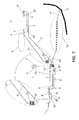
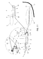
- It comprises at least one first lower main deposit 1 arranged at a lower level and at least one second upper main deposit 2 arranged at an upper level, both containing polluted water to be purified that has been previously diverted to one of the main deposits, while at the same time the bottom of both main deposits 1-2 are communicated with each other through at least one intermediate pipe 3 through which the polluted water is successively and alternatively circulated through the same in both directions, thereby obtaining a high oxygenation and a high agitation of the water under turbulent regime, while at the same time the main deposits 1-2 are out of the reach of a natural water stream, such as a river, and out of natural depressions, such as for example a lake, further highlighting that such deposits may have a great capacity.
- a natural water stream such as a river
- natural depressions such as for example a lake
- the transfer of water from the lower main deposit 1 to the upper main deposit 2 is carried out through a main pump 4, while the transfer of water from the upper main deposit 2 to the lower main deposit 1 is carried out by gravity, in this case the water passing through a turbine 5 through which energy is generated.
- the main pump 4 and the turbine 5 will be connected to the lower main deposit 1 through independent piping that will be joined to the intermediate pipe 3.
- the communication between the main deposits 1-2 is carried out through an intermediate pipe 3, wherein is sandwiched a reversible turbine that will alternately perform the functions of pumping when going up or turbine when going down.
- the main pump 4 and the turbine 5 are incorporated into a reversible hydroelectric plant 10, such that when the water circulates through the intermediate pipe 3 in one direction the water is pumped, while when it circulates in the opposite direction the water is turbined generating energy.
- an area of greater depth will be built which will act as suction vessel 6, allowing the priming of turbines and pumps. It is in these areas of greater depth where the ends of the intermediate pipe 3 are connected. In turn, these areas of greater depth are surrounded by a small curb 7 which will favor the retention of the decanted sludge at the bottom of the deposits in the alternative emptying processes of the same.
- aspiration 8 and purge 8' devices are installed for extracting the sludge, acting mainly in those areas of the bottom of the main deposits 1-2 where the pollutants accumulate in higher concentration by precipitation and decanting.
- These suction devices 8 are mobile.
- the suction devices 8 and the purge devices 8' for sludge extraction have the corresponding suction 22 and purge 22' pumps and flow into a cavity 9, where part of the water is discharged along with the concentration of the precipitated and decanted pollutants at the bottom of the main deposits 1-2.
- This cavity 9 comprises a ring structure by way of perimeter channeling that borders all the nozzle of each one of the main deposits 1-2. This low volume of water with concentration of pollutants contained in said cavity 9 is treated conventionally.
- the water treated in the cavity 9 once the pollutants have been separated by overflow or filtering can be recirculated, partially or in its entirety, through recirculation pipes 13 to the main deposits 1-2.
- the water flow rate treated in the aforementioned cavity 9 can be bypassed, through a drainage pipe 14, to an additional wastewater treatment station 15 that performs a natural and/or artificial purification through various conventional purification systems.
- the water flow rate from the cavity 9 and that has traveled through the additional wastewater treatment station 15, can be transferred at the end directly to a water stream 17, such as a river, canal, etc.; through a terminal pipe 16, since that water flow rate has a degree of purity according to current regulations.
- the polluted water into the main deposits 1-2 is poured first into an initial deposit 11, where the water receives a known prior treatment for treating the acidity and removing the suspended solids. Once said pre-treatment has been carried out, the water is transferred to one of the main deposits by means of an initial pipe 12.
- the bottom of this initial deposit also has a suction device 8 and other purge device 8', for the extraction of sludge, both devices 8-8' having in turn the corresponding suction 22 and purge 22' pumps and are connected to the cavity 9 leading to the same.
- the bottom of the main deposits 1-2, as well as the cavities 9 comprise a waterproof surface made of polyethylene and other materials, such as for example polyurethanes or asphalt. While at the same time said materials should enable all the deposits to be watertight in order to prevent leakage to the location environment.
- the perimeter channeling which constitutes the cavity 9 comprises two similar circuits that converge at a common cabin 20, each of such circuits having at least one overflow dam 18 and one terminal filter 19 allowing to separate the pollutants by decanting and filtering, the overflow dam 18 including emptying valves 21 arranged at different heights.
- the terminal filter 19 is made of gravel.
- the system of the invention provides a further treatment through a filtration device 23 placed at the suitable height in a bypass 24 that starts from the intermediate pipe 3 and integrates an opening and closing valve 25.
- an additional treatment through a filtration device 23 placed at the suitable height in an additional pipe 27 independent of the intermediate pipe 3 is provided, so that such additional pipe 27 communicates with at least the upper main deposit 2.
- system of the invention provides an additional treatment through a reverse osmosis device 26 placed at the suitable height on the additional pipe 27 independent of the intermediate pipe 3 ( Figure 8 ).
- the reverse osmosis device 26 is placed on the bypass 24 that starts from the intermediate pipe 3.
- an additional treatment is envisaged wherein the water contained in the main deposits 1 and 2, once most of the pollutants have been precipitated and led to a second cavity or perimeter channeling (28) where they are subjected to additional purification methods such as treatments of lagooning, nitrification/de-nitrification, sulfate-reducing bacteria cultures, or biological removal of phosphorus.
- This upper bypass 29 is a bypass that starts from the intermediate pipe 3 in proximity to the upper deposit 2.
- the upper bypass 29 can substitute and function as a surge tank.
- an opening and closing valve 30 In the interconnection of the upper bypass 29 with the intermediate pipe 3 is integrated an opening and closing valve 30.
- the transferring of water between the upper 2 and the lower 1 deposit is carried out through an impulse turbine 31 placed in a lower bypass 32 which starts from the intermediate pipe 3 and has a not submerged exit with drainage in the lower deposit 1, such lower bypass 32 integrating an opening and closing valve 33.
- the water flow rate that is decanted through the upper 29 and lower 32 bypass falls freely on the corresponding main deposits 1-2, thus improving the oxygenation and agitation of said water.
Landscapes
- Chemical & Material Sciences (AREA)
- Engineering & Computer Science (AREA)
- Life Sciences & Earth Sciences (AREA)
- Organic Chemistry (AREA)
- Environmental & Geological Engineering (AREA)
- Water Supply & Treatment (AREA)
- Hydrology & Water Resources (AREA)
- Chemical Kinetics & Catalysis (AREA)
- Mechanical Engineering (AREA)
- General Engineering & Computer Science (AREA)
- Combustion & Propulsion (AREA)
- Microbiology (AREA)
- Biodiversity & Conservation Biology (AREA)
- Power Engineering (AREA)
- Separation Using Semi-Permeable Membranes (AREA)
- Physical Water Treatments (AREA)
- Separation Of Suspended Particles By Flocculating Agents (AREA)
- Water Treatment By Sorption (AREA)
Priority Applications (1)
| Application Number | Priority Date | Filing Date | Title |
|---|---|---|---|
| PL12738147T PL2662338T4 (pl) | 2011-06-10 | 2012-06-08 | Układ do oczyszczania zanieczyszczonej wody i sposób oczyszczania |
Applications Claiming Priority (3)
| Application Number | Priority Date | Filing Date | Title |
|---|---|---|---|
| ES201130973A ES2397742B1 (es) | 2011-06-10 | 2011-06-10 | Sistema para depurar aguas contaminadas y procedimiento de depuración. |
| ES201230041A ES2424777B1 (es) | 2012-01-13 | 2012-01-13 | Sistema para depurar aguas contaminadas y procedimiento de depuracion, mejorado. |
| PCT/ES2012/070430 WO2012168531A2 (fr) | 2011-06-10 | 2012-06-08 | Système d'épuration d'eaux contaminées et procédé d'épuration |
Publications (2)
| Publication Number | Publication Date |
|---|---|
| EP2662338A2 true EP2662338A2 (fr) | 2013-11-13 |
| EP2662338B1 EP2662338B1 (fr) | 2019-01-16 |
Family
ID=46551580
Family Applications (1)
| Application Number | Title | Priority Date | Filing Date |
|---|---|---|---|
| EP12738147.3A Active EP2662338B1 (fr) | 2011-06-10 | 2012-06-08 | Système d'épuration d'eaux contaminées et procédé d'épuration |
Country Status (10)
| Country | Link |
|---|---|
| US (1) | US9260327B2 (fr) |
| EP (1) | EP2662338B1 (fr) |
| BR (1) | BR112013018132B1 (fr) |
| CA (1) | CA2838892C (fr) |
| ES (1) | ES2728275T3 (fr) |
| MX (1) | MX365217B (fr) |
| PE (1) | PE20141963A1 (fr) |
| PL (1) | PL2662338T4 (fr) |
| WO (1) | WO2012168531A2 (fr) |
| ZA (1) | ZA201309389B (fr) |
Families Citing this family (10)
| Publication number | Priority date | Publication date | Assignee | Title |
|---|---|---|---|---|
| CA2856196C (fr) | 2011-12-06 | 2020-09-01 | Masco Corporation Of Indiana | Distribution d'ozone dans un robinet |
| CN103496798B (zh) * | 2013-09-16 | 2015-03-25 | 戴杰康 | 循环呼吸滤清式河道永久清洁系统及其使用方法 |
| CN104671459B (zh) * | 2015-01-26 | 2016-05-04 | 常州大学 | 一种处理河道污染物的生物滤床 |
| CN115093008B (zh) | 2015-12-21 | 2024-05-14 | 德尔塔阀门公司 | 包括消毒装置的流体输送系统 |
| RS20160265A1 (sr) | 2016-04-21 | 2017-11-30 | Tomislav Tesla | Usisavanje nanosa iz akumulacija |
| CN107381980B (zh) * | 2017-09-07 | 2023-07-04 | 天津市水利科学研究院 | 一种农村小流域污水净化系统 |
| CN109020059A (zh) * | 2018-08-06 | 2018-12-18 | 钟秀国 | 一种新式的河道用水电及水质净化一体装置 |
| EP3837035B1 (fr) | 2018-08-16 | 2026-05-20 | Emd Millipore Corp | Dispositif de biotraitement fermé |
| CN112811705B (zh) * | 2020-12-31 | 2022-06-14 | 宁夏师范学院 | 一种环境工程用化学污水处理装置 |
| CA3234998C (fr) * | 2021-10-12 | 2025-02-11 | Glen D. Lindbo | Ensemble décanteur autonome extractible compact |
Family Cites Families (10)
| Publication number | Priority date | Publication date | Assignee | Title |
|---|---|---|---|---|
| US5297895A (en) * | 1991-09-16 | 1994-03-29 | Ron Johnson | Method and apparatus for controlling silt erosion |
| US6000880A (en) * | 1997-12-23 | 1999-12-14 | Halus; William J. | Sewage water purification/reuse/redistribution, flood control, and power generating system |
| US6068773A (en) * | 1998-05-01 | 2000-05-30 | Sheaffer International Ltd. | Single-cell wastewater reclamation and reuse system |
| JP3484079B2 (ja) * | 1998-07-29 | 2004-01-06 | 敏男 酒井 | クリーンウォータシステム及びその構造 |
| US20030082004A1 (en) * | 2001-10-31 | 2003-05-01 | Dennis Wilkerson | Bunker drain system |
| DE20306503U1 (de) | 2003-04-26 | 2003-07-17 | eta AG, 03042 Cottbus | Anordnung für die Behandlung von sauren Bergbauwässern |
| DE102004006084B4 (de) | 2004-02-07 | 2010-01-21 | Brandenburgische Technische Universität Cottbus | Verfahren und Anordnung zur Behandlung saurer und sulfathaltiger Abwässer des Bergbaus |
| US20080023963A1 (en) * | 2006-07-26 | 2008-01-31 | Stephen Perich | Hydroelectric power and desalination |
| US7866919B2 (en) * | 2007-04-12 | 2011-01-11 | Natural Energy Resources Company | System and method for controlling water flow between multiple reservoirs of a renewable water and energy system |
| FI119148B (fi) | 2007-07-05 | 2008-08-15 | Biolan Oy | Laitteisto ja sen käyttö fosforin saostamiseksi jätevedestä |
-
2012
- 2012-06-08 WO PCT/ES2012/070430 patent/WO2012168531A2/fr not_active Ceased
- 2012-06-08 EP EP12738147.3A patent/EP2662338B1/fr active Active
- 2012-06-08 BR BR112013018132A patent/BR112013018132B1/pt active IP Right Grant
- 2012-06-08 US US13/884,724 patent/US9260327B2/en active Active
- 2012-06-08 PL PL12738147T patent/PL2662338T4/pl unknown
- 2012-06-08 PE PE2014001476A patent/PE20141963A1/es active IP Right Grant
- 2012-06-08 ES ES12738147T patent/ES2728275T3/es active Active
- 2012-06-08 CA CA2838892A patent/CA2838892C/fr active Active
- 2012-06-08 MX MX2013014590A patent/MX365217B/es active IP Right Grant
-
2013
- 2013-12-12 ZA ZA2013/09389A patent/ZA201309389B/en unknown
Non-Patent Citations (1)
| Title |
|---|
| See references of WO2012168531A2 * |
Also Published As
| Publication number | Publication date |
|---|---|
| PL2662338T3 (pl) | 2019-09-30 |
| US20150151989A1 (en) | 2015-06-04 |
| ES2728275T3 (es) | 2019-10-23 |
| BR112013018132A2 (pt) | 2016-11-08 |
| CA2838892C (fr) | 2020-03-10 |
| CA2838892A1 (fr) | 2012-12-13 |
| WO2012168531A2 (fr) | 2012-12-13 |
| PL2662338T4 (pl) | 2019-10-31 |
| EP2662338B1 (fr) | 2019-01-16 |
| US9260327B2 (en) | 2016-02-16 |
| MX2013014590A (es) | 2014-02-27 |
| MX365217B (es) | 2019-05-27 |
| BR112013018132B1 (pt) | 2020-04-14 |
| ZA201309389B (en) | 2014-08-27 |
| PE20141963A1 (es) | 2014-11-28 |
| WO2012168531A3 (fr) | 2013-01-31 |
Similar Documents
| Publication | Publication Date | Title |
|---|---|---|
| EP2662338B1 (fr) | Système d'épuration d'eaux contaminées et procédé d'épuration | |
| US20080142438A1 (en) | Wetland water treatment system | |
| KR100944122B1 (ko) | 강우유출수 및 평상시 기저유량을 동시에 처리할 수 있는 인공습지 | |
| CN104944631A (zh) | 高浓度切削液污水的预处理方法 | |
| GB2272171A (en) | Treatment of effluents | |
| Schulz et al. | Treating surface waters for communities in developing countries | |
| US20090230054A1 (en) | Contaminant Removal System And Method For A Body Of Water | |
| KR100968272B1 (ko) | 광산폐수 처리장치 | |
| CN105899464A (zh) | 用于处理水或废水的系统和方法 | |
| CN108046476A (zh) | 一种涉及切削/研磨/抛光工艺废水处理的装置及工艺 | |
| CN105129969A (zh) | 周边过滤出水生化沉淀池 | |
| US7014776B1 (en) | Contaminant removal method for a body of water | |
| CN105502748B (zh) | 污水一体化处理方法 | |
| CN104986922A (zh) | 一种污水回用系统和污水处理方法 | |
| CN111392964B (zh) | 一种雨污合流泵站污水的处理方法及其装置 | |
| Skolubovich et al. | Cleaning and reusing backwash water of water treatment plants | |
| KR101445209B1 (ko) | 이동형 음용수 공급장치 | |
| KR101507020B1 (ko) | 복수의 취수처리부를 포함하는 해수 담수화 장치 및 이의 제어방법 | |
| KR20100034087A (ko) | 다수의 공급라인이 구비된 패키지형 정수처리 시스템 | |
| KR200331355Y1 (ko) | 우수 및 하천수 정화구조 | |
| RU2151748C1 (ru) | Станция очистки сточных вод и технологических растворов | |
| US7510660B1 (en) | Contaminant removal method for a body of water | |
| KR101991868B1 (ko) | 지표수와 해수를 처리하는 수처리 장치를 이용한 수처리 방법 | |
| ES2424777A2 (es) | Sistema para depurar aguas contaminadas y procedimiento de depuración, mejorado. | |
| CN220999340U (zh) | 一种用于多级沉淀池的油水分离结构 |
Legal Events
| Date | Code | Title | Description |
|---|---|---|---|
| PUAI | Public reference made under article 153(3) epc to a published international application that has entered the european phase |
Free format text: ORIGINAL CODE: 0009012 |
|
| 17P | Request for examination filed |
Effective date: 20121228 |
|
| AK | Designated contracting states |
Kind code of ref document: A2 Designated state(s): AL AT BE BG CH CY CZ DE DK EE ES FI FR GB GR HR HU IE IS IT LI LT LU LV MC MK MT NL NO PL PT RO RS SE SI SK SM TR |
|
| AX | Request for extension of the european patent |
Extension state: BA ME |
|
| 17Q | First examination report despatched |
Effective date: 20140805 |
|
| STAA | Information on the status of an ep patent application or granted ep patent |
Free format text: STATUS: EXAMINATION IS IN PROGRESS |
|
| GRAP | Despatch of communication of intention to grant a patent |
Free format text: ORIGINAL CODE: EPIDOSNIGR1 |
|
| STAA | Information on the status of an ep patent application or granted ep patent |
Free format text: STATUS: GRANT OF PATENT IS INTENDED |
|
| INTG | Intention to grant announced |
Effective date: 20180817 |
|
| GRAS | Grant fee paid |
Free format text: ORIGINAL CODE: EPIDOSNIGR3 |
|
| GRAJ | Information related to disapproval of communication of intention to grant by the applicant or resumption of examination proceedings by the epo deleted |
Free format text: ORIGINAL CODE: EPIDOSDIGR1 |
|
| GRAL | Information related to payment of fee for publishing/printing deleted |
Free format text: ORIGINAL CODE: EPIDOSDIGR3 |
|
| STAA | Information on the status of an ep patent application or granted ep patent |
Free format text: STATUS: EXAMINATION IS IN PROGRESS |
|
| GRAR | Information related to intention to grant a patent recorded |
Free format text: ORIGINAL CODE: EPIDOSNIGR71 |
|
| STAA | Information on the status of an ep patent application or granted ep patent |
Free format text: STATUS: GRANT OF PATENT IS INTENDED |
|
| GRAA | (expected) grant |
Free format text: ORIGINAL CODE: 0009210 |
|
| STAA | Information on the status of an ep patent application or granted ep patent |
Free format text: STATUS: THE PATENT HAS BEEN GRANTED |
|
| INTC | Intention to grant announced (deleted) | ||
| AK | Designated contracting states |
Kind code of ref document: B1 Designated state(s): AL AT BE BG CH CY CZ DE DK EE ES FI FR GB GR HR HU IE IS IT LI LT LU LV MC MK MT NL NO PL PT RO RS SE SI SK SM TR |
|
| AX | Request for extension of the european patent |
Extension state: BA ME |
|
| INTG | Intention to grant announced |
Effective date: 20181210 |
|
| REG | Reference to a national code |
Ref country code: GB Ref legal event code: FG4D |
|
| REG | Reference to a national code |
Ref country code: CH Ref legal event code: EP |
|
| REG | Reference to a national code |
Ref country code: IE Ref legal event code: FG4D |
|
| REG | Reference to a national code |
Ref country code: DE Ref legal event code: R096 Ref document number: 602012055991 Country of ref document: DE |
|
| REG | Reference to a national code |
Ref country code: AT Ref legal event code: REF Ref document number: 1089572 Country of ref document: AT Kind code of ref document: T Effective date: 20190215 |
|
| REG | Reference to a national code |
Ref country code: NL Ref legal event code: MP Effective date: 20190116 |
|
| REG | Reference to a national code |
Ref country code: LT Ref legal event code: MG4D |
|
| PG25 | Lapsed in a contracting state [announced via postgrant information from national office to epo] |
Ref country code: NL Free format text: LAPSE BECAUSE OF FAILURE TO SUBMIT A TRANSLATION OF THE DESCRIPTION OR TO PAY THE FEE WITHIN THE PRESCRIBED TIME-LIMIT Effective date: 20190116 |
|
| REG | Reference to a national code |
Ref country code: AT Ref legal event code: MK05 Ref document number: 1089572 Country of ref document: AT Kind code of ref document: T Effective date: 20190116 |
|
| PG25 | Lapsed in a contracting state [announced via postgrant information from national office to epo] |
Ref country code: LT Free format text: LAPSE BECAUSE OF FAILURE TO SUBMIT A TRANSLATION OF THE DESCRIPTION OR TO PAY THE FEE WITHIN THE PRESCRIBED TIME-LIMIT Effective date: 20190116 Ref country code: FI Free format text: LAPSE BECAUSE OF FAILURE TO SUBMIT A TRANSLATION OF THE DESCRIPTION OR TO PAY THE FEE WITHIN THE PRESCRIBED TIME-LIMIT Effective date: 20190116 Ref country code: SE Free format text: LAPSE BECAUSE OF FAILURE TO SUBMIT A TRANSLATION OF THE DESCRIPTION OR TO PAY THE FEE WITHIN THE PRESCRIBED TIME-LIMIT Effective date: 20190116 Ref country code: NO Free format text: LAPSE BECAUSE OF FAILURE TO SUBMIT A TRANSLATION OF THE DESCRIPTION OR TO PAY THE FEE WITHIN THE PRESCRIBED TIME-LIMIT Effective date: 20190416 Ref country code: PT Free format text: LAPSE BECAUSE OF FAILURE TO SUBMIT A TRANSLATION OF THE DESCRIPTION OR TO PAY THE FEE WITHIN THE PRESCRIBED TIME-LIMIT Effective date: 20190516 |
|
| PG25 | Lapsed in a contracting state [announced via postgrant information from national office to epo] |
Ref country code: GR Free format text: LAPSE BECAUSE OF FAILURE TO SUBMIT A TRANSLATION OF THE DESCRIPTION OR TO PAY THE FEE WITHIN THE PRESCRIBED TIME-LIMIT Effective date: 20190417 Ref country code: BG Free format text: LAPSE BECAUSE OF FAILURE TO SUBMIT A TRANSLATION OF THE DESCRIPTION OR TO PAY THE FEE WITHIN THE PRESCRIBED TIME-LIMIT Effective date: 20190416 Ref country code: RS Free format text: LAPSE BECAUSE OF FAILURE TO SUBMIT A TRANSLATION OF THE DESCRIPTION OR TO PAY THE FEE WITHIN THE PRESCRIBED TIME-LIMIT Effective date: 20190116 Ref country code: IS Free format text: LAPSE BECAUSE OF FAILURE TO SUBMIT A TRANSLATION OF THE DESCRIPTION OR TO PAY THE FEE WITHIN THE PRESCRIBED TIME-LIMIT Effective date: 20190516 Ref country code: HR Free format text: LAPSE BECAUSE OF FAILURE TO SUBMIT A TRANSLATION OF THE DESCRIPTION OR TO PAY THE FEE WITHIN THE PRESCRIBED TIME-LIMIT Effective date: 20190116 Ref country code: LV Free format text: LAPSE BECAUSE OF FAILURE TO SUBMIT A TRANSLATION OF THE DESCRIPTION OR TO PAY THE FEE WITHIN THE PRESCRIBED TIME-LIMIT Effective date: 20190116 |
|
| REG | Reference to a national code |
Ref country code: DE Ref legal event code: R097 Ref document number: 602012055991 Country of ref document: DE |
|
| REG | Reference to a national code |
Ref country code: ES Ref legal event code: FG2A Ref document number: 2728275 Country of ref document: ES Kind code of ref document: T3 Effective date: 20191023 |
|
| PG25 | Lapsed in a contracting state [announced via postgrant information from national office to epo] |
Ref country code: AT Free format text: LAPSE BECAUSE OF FAILURE TO SUBMIT A TRANSLATION OF THE DESCRIPTION OR TO PAY THE FEE WITHIN THE PRESCRIBED TIME-LIMIT Effective date: 20190116 Ref country code: EE Free format text: LAPSE BECAUSE OF FAILURE TO SUBMIT A TRANSLATION OF THE DESCRIPTION OR TO PAY THE FEE WITHIN THE PRESCRIBED TIME-LIMIT Effective date: 20190116 Ref country code: AL Free format text: LAPSE BECAUSE OF FAILURE TO SUBMIT A TRANSLATION OF THE DESCRIPTION OR TO PAY THE FEE WITHIN THE PRESCRIBED TIME-LIMIT Effective date: 20190116 Ref country code: DK Free format text: LAPSE BECAUSE OF FAILURE TO SUBMIT A TRANSLATION OF THE DESCRIPTION OR TO PAY THE FEE WITHIN THE PRESCRIBED TIME-LIMIT Effective date: 20190116 Ref country code: SK Free format text: LAPSE BECAUSE OF FAILURE TO SUBMIT A TRANSLATION OF THE DESCRIPTION OR TO PAY THE FEE WITHIN THE PRESCRIBED TIME-LIMIT Effective date: 20190116 Ref country code: IT Free format text: LAPSE BECAUSE OF FAILURE TO SUBMIT A TRANSLATION OF THE DESCRIPTION OR TO PAY THE FEE WITHIN THE PRESCRIBED TIME-LIMIT Effective date: 20190116 Ref country code: RO Free format text: LAPSE BECAUSE OF FAILURE TO SUBMIT A TRANSLATION OF THE DESCRIPTION OR TO PAY THE FEE WITHIN THE PRESCRIBED TIME-LIMIT Effective date: 20190116 Ref country code: CZ Free format text: LAPSE BECAUSE OF FAILURE TO SUBMIT A TRANSLATION OF THE DESCRIPTION OR TO PAY THE FEE WITHIN THE PRESCRIBED TIME-LIMIT Effective date: 20190116 |
|
| PLBE | No opposition filed within time limit |
Free format text: ORIGINAL CODE: 0009261 |
|
| STAA | Information on the status of an ep patent application or granted ep patent |
Free format text: STATUS: NO OPPOSITION FILED WITHIN TIME LIMIT |
|
| PG25 | Lapsed in a contracting state [announced via postgrant information from national office to epo] |
Ref country code: SM Free format text: LAPSE BECAUSE OF FAILURE TO SUBMIT A TRANSLATION OF THE DESCRIPTION OR TO PAY THE FEE WITHIN THE PRESCRIBED TIME-LIMIT Effective date: 20190116 |
|
| 26N | No opposition filed |
Effective date: 20191017 |
|
| REG | Reference to a national code |
Ref country code: DE Ref legal event code: R119 Ref document number: 602012055991 Country of ref document: DE |
|
| PG25 | Lapsed in a contracting state [announced via postgrant information from national office to epo] |
Ref country code: MC Free format text: LAPSE BECAUSE OF FAILURE TO SUBMIT A TRANSLATION OF THE DESCRIPTION OR TO PAY THE FEE WITHIN THE PRESCRIBED TIME-LIMIT Effective date: 20190116 |
|
| REG | Reference to a national code |
Ref country code: CH Ref legal event code: PL |
|
| PG25 | Lapsed in a contracting state [announced via postgrant information from national office to epo] |
Ref country code: SI Free format text: LAPSE BECAUSE OF FAILURE TO SUBMIT A TRANSLATION OF THE DESCRIPTION OR TO PAY THE FEE WITHIN THE PRESCRIBED TIME-LIMIT Effective date: 20190116 |
|
| REG | Reference to a national code |
Ref country code: BE Ref legal event code: MM Effective date: 20190630 |
|
| PG25 | Lapsed in a contracting state [announced via postgrant information from national office to epo] |
Ref country code: TR Free format text: LAPSE BECAUSE OF FAILURE TO SUBMIT A TRANSLATION OF THE DESCRIPTION OR TO PAY THE FEE WITHIN THE PRESCRIBED TIME-LIMIT Effective date: 20190116 |
|
| PG25 | Lapsed in a contracting state [announced via postgrant information from national office to epo] |
Ref country code: IE Free format text: LAPSE BECAUSE OF NON-PAYMENT OF DUE FEES Effective date: 20190608 Ref country code: DE Free format text: LAPSE BECAUSE OF NON-PAYMENT OF DUE FEES Effective date: 20200101 |
|
| PG25 | Lapsed in a contracting state [announced via postgrant information from national office to epo] |
Ref country code: CH Free format text: LAPSE BECAUSE OF NON-PAYMENT OF DUE FEES Effective date: 20190630 Ref country code: BE Free format text: LAPSE BECAUSE OF NON-PAYMENT OF DUE FEES Effective date: 20190630 Ref country code: LU Free format text: LAPSE BECAUSE OF NON-PAYMENT OF DUE FEES Effective date: 20190608 Ref country code: LI Free format text: LAPSE BECAUSE OF NON-PAYMENT OF DUE FEES Effective date: 20190630 |
|
| PG25 | Lapsed in a contracting state [announced via postgrant information from national office to epo] |
Ref country code: FR Free format text: LAPSE BECAUSE OF NON-PAYMENT OF DUE FEES Effective date: 20190630 |
|
| PG25 | Lapsed in a contracting state [announced via postgrant information from national office to epo] |
Ref country code: CY Free format text: LAPSE BECAUSE OF FAILURE TO SUBMIT A TRANSLATION OF THE DESCRIPTION OR TO PAY THE FEE WITHIN THE PRESCRIBED TIME-LIMIT Effective date: 20190116 |
|
| PG25 | Lapsed in a contracting state [announced via postgrant information from national office to epo] |
Ref country code: MT Free format text: LAPSE BECAUSE OF FAILURE TO SUBMIT A TRANSLATION OF THE DESCRIPTION OR TO PAY THE FEE WITHIN THE PRESCRIBED TIME-LIMIT Effective date: 20190116 Ref country code: HU Free format text: LAPSE BECAUSE OF FAILURE TO SUBMIT A TRANSLATION OF THE DESCRIPTION OR TO PAY THE FEE WITHIN THE PRESCRIBED TIME-LIMIT; INVALID AB INITIO Effective date: 20120608 |
|
| PG25 | Lapsed in a contracting state [announced via postgrant information from national office to epo] |
Ref country code: MK Free format text: LAPSE BECAUSE OF FAILURE TO SUBMIT A TRANSLATION OF THE DESCRIPTION OR TO PAY THE FEE WITHIN THE PRESCRIBED TIME-LIMIT Effective date: 20190116 |
|
| PGFP | Annual fee paid to national office [announced via postgrant information from national office to epo] |
Ref country code: PL Payment date: 20250520 Year of fee payment: 14 |
|
| PGFP | Annual fee paid to national office [announced via postgrant information from national office to epo] |
Ref country code: GB Payment date: 20250627 Year of fee payment: 14 |
|
| PGFP | Annual fee paid to national office [announced via postgrant information from national office to epo] |
Ref country code: ES Payment date: 20250702 Year of fee payment: 14 |