EP2662507B1 - Procédé de pose d'un revêtement et élément de panneau pour un revêtement - Google Patents
Procédé de pose d'un revêtement et élément de panneau pour un revêtement Download PDFInfo
- Publication number
- EP2662507B1 EP2662507B1 EP13002305.4A EP13002305A EP2662507B1 EP 2662507 B1 EP2662507 B1 EP 2662507B1 EP 13002305 A EP13002305 A EP 13002305A EP 2662507 B1 EP2662507 B1 EP 2662507B1
- Authority
- EP
- European Patent Office
- Prior art keywords
- groove
- longitudinal edge
- panel element
- edge
- spring
- Prior art date
- Legal status (The legal status is an assumption and is not a legal conclusion. Google has not performed a legal analysis and makes no representation as to the accuracy of the status listed.)
- Active
Links
Images




Classifications
-
- E—FIXED CONSTRUCTIONS
- E04—BUILDING
- E04F—FINISHING WORK ON BUILDINGS, e.g. STAIRS, FLOORS
- E04F15/00—Flooring
- E04F15/02—Flooring or floor layers composed of a number of similar elements
-
- E—FIXED CONSTRUCTIONS
- E04—BUILDING
- E04F—FINISHING WORK ON BUILDINGS, e.g. STAIRS, FLOORS
- E04F15/00—Flooring
- E04F15/02—Flooring or floor layers composed of a number of similar elements
- E04F15/02005—Construction of joints, e.g. dividing strips
- E04F15/02033—Joints with beveled or recessed upper edges
-
- E—FIXED CONSTRUCTIONS
- E04—BUILDING
- E04F—FINISHING WORK ON BUILDINGS, e.g. STAIRS, FLOORS
- E04F2201/00—Joining sheets or plates or panels
- E04F2201/01—Joining sheets, plates or panels with edges in abutting relationship
- E04F2201/0138—Joining sheets, plates or panels with edges in abutting relationship by moving the sheets, plates or panels perpendicular to the main plane
-
- E—FIXED CONSTRUCTIONS
- E04—BUILDING
- E04F—FINISHING WORK ON BUILDINGS, e.g. STAIRS, FLOORS
- E04F2201/00—Joining sheets or plates or panels
- E04F2201/01—Joining sheets, plates or panels with edges in abutting relationship
- E04F2201/0153—Joining sheets, plates or panels with edges in abutting relationship by rotating the sheets, plates or panels around an axis which is parallel to the abutting edges, possibly combined with a sliding movement
-
- E—FIXED CONSTRUCTIONS
- E04—BUILDING
- E04F—FINISHING WORK ON BUILDINGS, e.g. STAIRS, FLOORS
- E04F2201/00—Joining sheets or plates or panels
- E04F2201/02—Non-undercut connections, e.g. tongue and groove connections
- E04F2201/025—Non-undercut connections, e.g. tongue and groove connections with tongue and grooves alternating transversally in the direction of the thickness of the panel, e.g. multiple tongue and grooves oriented parallel to each other
-
- E—FIXED CONSTRUCTIONS
- E04—BUILDING
- E04F—FINISHING WORK ON BUILDINGS, e.g. STAIRS, FLOORS
- E04F2201/00—Joining sheets or plates or panels
- E04F2201/04—Other details of tongues or grooves
- E04F2201/041—Tongues or grooves with slits or cuts for expansion or flexibility
Definitions
- the invention relates to a method for laying a covering, in particular a floor, wall or ceiling covering, wherein the covering has a plurality of similar, interconnected panel elements, wherein the panel element has a base body with mutually opposite longitudinal edges and opposite transverse edges, wherein on one longitudinal edge a L Lucasskantennutkontur and on the other longitudinal edge a corresponding Lekskantenfederkontur is provided, wherein on one transverse edge a Querkantennutkontur and at the other transverse edge a corresponding transverse edge spring contour is provided and adjacent panel elements are connected to each other at their adjacent longitudinal edges and their adjacent transverse edges , Furthermore, the present invention relates to a panel element for a covering, in particular a floor, wall or ceiling covering, wherein the covering comprises a plurality of similar, interconnected panel elements, preferably provided for laying according to the aforementioned method, wherein the panel element having a base body having opposite longitudinal edges and opposing transverse edges, wherein on one longitudinal edge a Lssenskantennutkontur and
- planks which is based on a locking of the transverse edge by push button systems.
- a pressure point must be overcome, which naturally opposes only low holding forces against loosening of the connection.
- connection is the lateral pivoting / connecting a complete series of interconnected at the transverse edges planks, which - after joining all planks in the transverse edges - is supported as an entire row by wedges and then pivoted into the longitudinal edge of already laid planks .
- the support of a tool is required for longitudinal edge joining in order to overcome corresponding pressure points and to insert the row of planks as a whole into the longitudinal edge of the already laid planks.
- Newer systems which are known from practice, have in the region of a transverse edge of an additional component in the manner of a spring bolt, which allows joining of the planks.
- the laying takes place in such a way that the plank to be laid is inserted with its one longitudinal edge in the longitudinal edge of the already laid row of planks.
- the interlocking of adjacent planks of a series takes place by the accurately fitting lowering of the plank to be laid on the already laid plank.
- pivoting down the board to be laid it comes to a locking of the adjacent transverse edges due to the spring bolt.
- Problems can arise in this system, in particular, when an already laid plank is taken up again. This can lead to damage of the spring bolt with the result that the next joining process is not readily possible.
- Another disadvantage of this known system is the reduced fit due to the added tolerances of the various components. This can ultimately lead to no smooth transition between adjacent planks in the area of the top edges.
- this known system is complicated and expensive due to the need for additional spring bolt
- Object of the present invention is therefore to provide a method for laying a covering of the type mentioned above and related panel elements for a covering available, the installation easily possible and the related panels or the flooring produced therefrom should be inexpensive to produce.
- the attachment of the panel element to be laid to the already laid panel element for transverse edge joining with an attachment angle ⁇ of at least 3 ° and a maximum of 50 °.
- any intermediate interval within the aforementioned range limits is possible, such as 4 ° to 45 °.
- the transverse edge formation is such that a transverse edge insertion in the aforementioned interval of the attachment angle is possible. In detail, this will be discussed below.
- the panel element to be laid is to be brought as close as possible to the longitudinal edge of the last laid row of panel elements after the transverse edge joining.
- this can take place in that the transverse edge joining takes place already during the oblique application so that the longitudinal edges to be provided are as close as possible to one another. In this way, then only a small and, in the best case, no displacement in the horizontal direction is required for the longitudinal edge joining.
- Even if the already transversely mounted, to be laid panel element has not been transversely exactly in the aforementioned manner, so that the long edges to be equipped abut very close to each other, only a short shift to L josskanten colgung must be done.
- the spring of the longitudinal edge rests after lowering the panel member on a designated contact surface of the lower groove cheek of the longitudinal edge. This not only results in a good and secure support of the spring for subsequent insertion into the groove, it is also provided a place for the pivot point in the subsequent pivoting up of the panel element to be laid available.
- the panel element mentioned at the beginning has a special structural design.
- the panel element according to the invention may not necessarily be used only for laying according to the aforementioned method.
- the ratio of the projection of the lower groove cheek to the upper groove cheek of the longitudinal edge to the projection of the spring of the longitudinal edge is between 1.5 and 3.1, preferably between 1.95 and 2.7 between 2.1 and 2.5 and in particular at least 2.3.
- the ratio of the projection of the lower groove cheek to the upper groove cheek of the transverse edge to the projection of the spring of the transverse edge between 0.4 and 1.85, preferably between 0.6 and 1.5, more preferably between 0 , 7 and 1.1 and in particular at least 0.9.
- a comparatively short spring with a comparatively long lower groove cheek is used as a result in the longitudinal edge contour to allow a safe swinging in at a small joint angle.
- the transverse edge contouring is carried out completely differently.
- the spring is longer and the lower groove cheek of the transverse edge has a comparatively short length, which favors the displacement necessary for the longitudinal edge joining in the method according to the invention.
- the longitudinal and transverse edge contour is different, it is basically also possible to approximate the abovementioned contours to one another, to the extent that insertion of a longitudinal edge into a transverse edge and vice versa is possible.
- the ratio of the projection of the spring of the longitudinal edge to the distance between the end face of the upper groove cheek of the longitudinal edge and the detent groove of the longitudinal edge is between 2.6 and 0.6, preferably between 1.7 and 0.8, more preferably between 1.25 and 1, 0 and in particular at least 1.09.
- the ratio of the projection of the spring of the transverse edge to the distance of the end face of the upper groove cheek of the transverse edge to the locking groove of the transverse edge between 15 and 25, preferably between 18 and 22, more preferably between 19 and 21 and especially at least 20.3.
- the ratio values indicated above make it clear that the lower groove cheek is relatively short and the detent point is close to the displacement area. In this way, on the one hand, the frictional resistance in the necessary horizontal sliding movement for longitudinal edge joining is reduced, on the other hand results from the immediate vicinity of the locking groove to the end face of the upper groove no torque at uneven or oblique application of force during horizontal displacement of the panel element to be laid for Lssensskanten Stahl.
- the coating which may include one or more layers, may be a plastic coating, such as plastic.
- plastic coating such as plastic.
- PVC polyvinyl urethane
- PUR a textile coating
- cork and / or linoleum coating or a so-called Woodpowder coating act. It is understood that several different coatings, in particular of the aforementioned type, can be provided on a wood-based or plastic plate.
- the panel element 2 or the base body 3 has a L Lucasskantennutkonturen on one longitudinal edge 4, while at the other longitudinal edge 5 a corresponding longitudinal edge spring contour is provided.
- "Corresponding” in this context means that the dimensions of the longitudinal edge contours of the two longitudinal edges 4, 5 are such that an insertion of the one contour into the other contour is possible.
- a transverse edge groove contour is provided on one transverse edge 6, while a corresponding transverse edge spring contour is provided on the other transverse edge 7.
- the transverse edges 6, 7 are formed "corresponding" so that they can be joined together. Incidentally, this is the case, for example Fig. 1 , adjacent panel elements 2 at their adjacent longitudinal edges 4, 5 and their adjacent transverse edges 6, 7 connected to each other.
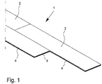
- Fig. 1 a possible initial situation is shown, in which a row is already laid with panel elements 2 and in the next row at least one already laid panel element 2 is located.
- a plurality of already laid rows of panels 2 can be provided, It is understood that, of course, first a row is laid during installation and then started laying the next row. When laying the first row, adjacent panel elements 2 are connected to one another only at their transverse edges 6, 7. Subsequently, the first panel element 2 is then applied in the next row, wherein the adjacent longitudinal edges 4, 5 are joined together become.
- the in Fig. 1 already lying panel element 2 pivoted longitudinal edge and lowered so that it - like the already laid panel elements 2 - rests on the substrate, not shown.
- the laying is from left to right.
- the invention is not limited thereto.
- FIG. 2 shows the longitudinal edge 4 with the L Lucasskantennutkontur.
- This contour has an upper groove cheek 8 and a lower groove cheek 9.
- the groove cheek 9 is longer than the groove cheek 8, is about this so over to the outside.
- the groove 10 is located between the groove cheeks 8, 9.
- the lower free end of the groove cheek 8 has a chamfer 11, so that the groove 10 widens outwards.
- the lower groove leg 9 has in the region of its free end a latching groove 12, which is provided to the outside with an inlet curvature 13.
- the lower groove cheek 9 has over the outer end face 14 of the upper groove cheek 8 on a supernatant a.
- the longitudinal edge spring contour has a spring 15 which protrudes from the upper end face 16 with a projection c.
- the supernatant c is 2.55 mm, where it can be basically between 2 and 3 mm.
- a locking cam 18 In extension of the bottom 17 of the spring 15 is a locking cam 18 which is provided for engagement in the locking groove 12. In the joined state, the end faces 14 and 16 abut each other.
- the transverse edge groove contour has an upper groove cheek 19 and a lower groove cheek 20. At the outer free end of the upper groove cheek 19, this is bevelled, wherein in the illustrated embodiment, two bevels 22, 23 are provided with different pitches between the two groove cheeks 19, 20. At the Abschrägunen 22, 23, the outer end surface 24 connects.
- the lower groove cheek 20 has a latching groove 25, which is provided with an inlet curvature 26.
- the lower groove cheek 20 projects with a projection d over the outer end face 24 of the upper groove cheek 19.
- the supernatant is d 3.31 mm, wherein the supernatant may be in an interval between 2.5 and 4.5 mm, each individual value is possible.
- the clear distance e of the outer end face 24 to the locking groove 25 is extremely low and is present only 0.18 mm. Basically, the distance e can be between 0.10 and 0.30 mm, whereby each individual value is possible.
- the longitudinal edge contour corresponding to FIGS. 2 and 3 from the transverse edge contour according to the 4 and 5 different.
- the spring 15 of the longitudinal edge 5 protrudes less than the spring 27 of the transverse edge 7.
- the lower groove cheek 9 of the longitudinal edge 4 is significantly longer than the lower groove cheek 20 of the transverse edge. 6
- the key difference is that the distances b and e are significantly different.
- the distance b of the longitudinal edge 4 is significantly greater than the distance e of the transverse edge. 6
- the longitudinal edge contour uses a rather short spring 15 with a rather long lower groove cheek 9
- the transverse edge contour uses a spring 27 which is relatively longer with a rather shorter lower groove cheek 20.
- Fig. 6 It is shown that the panel element 2 to be laid is supplied with its transverse edge 7, which has the transverse edge spring contour, obliquely in the direction of the transverse edge 6 of the already laid, already longitudinally edged panel element 2. Subsequently, the transverse edge 7 of the obliquely supplied, to be laid panel element 2 is inserted into the transverse edge 6 of the already laid panel element 2, as shown in Fig. 7 is shown. This results in a joining of the transverse edge, with no tool for Querenkanten Stahl required. A wedging o. The like. Is not required. Finally, the process of cross-over can be done relatively easily and easily by a two handed feeder by the publisher. Since the adjacent panel elements 2 are joined only in the region of their narrow transverse edges 6, 7, the result is a narrow joining area. By the transverse edge geometry, which will be discussed in more detail later, results in the rest of a defined Einschwenkvorgang.
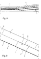
- FIG. 9 shows the state in which the panel element 2 to be laid has been lowered.
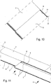
- the transverse edges 6, 7 are then inserted into one another, while a gap 31 results between the marginal edge of the longitudinal edge 4 of the already laid panel elements 2 and the marginal edge of the longitudinal edge 5 of the panel element 2 to be laid
- Fig. 10 is shown a little clearer.
- the panel element 2 to be laid can be displaced with little effort in the direction of arrow x with simultaneous transverse edge joining. Moreover, it is due to the small length of the distance e and thus the proximity of the locking groove 25 to the outer end face 24 so that a comparatively low frictional resistance and otherwise no or at most a low torque in the horizontal displacement in the direction of the transverse contour, ie in the direction of arrow X results.
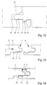
- FIGS. 13 and 14 is shown in side view moving in the direction of arrow X.
- the panel element 2 is already transversely placed in this state.
- the horizontal displacement of the panel 2 to be laid in the direction of arrow X takes place until the locking cam 18 of the longitudinal edge 5 abuts against the front end face 35 of the lower groove cheek 9.
- the bottom 17 of the spring 15 on the support surface 36 which results from the comparatively large distance b, with some coverage of the bottom 17 and the support surface 16 safely.
- the latching area is slightly lowered relative to the support surface 36, so that there is no contact of the underside 17 in this area. The support thus takes place only in the region of the support surface 36.
- this panel element 2 After lifting the panel element 2 to be laid, for example, at a joining angle of 10 °, this panel element 2 is inserted with its longitudinal edge 5 in the longitudinal edge 4 of the already laid row of panel elements 2, so that then gives the Lekssskanten colgung. This joining condition is in Fig. 16 shown.
- FIGS. 18 to 22 the Lekskanten colgung is again schematically shown as a section.
- the panel element 2 to be laid is shown on the left, while on the right a panel element 2 of the previous laying row is shown.
- Fig. 18 illustrates the inclination of the panel element to be laid 2 at the angle of attachment ⁇ to the transverse edge joining.
- the panel element 2 is as close as possible to the in Fig. 18 On the right panel element 2 has been moved.
- the panel element 2 to be laid is lowered and, if necessary, pushed up against the panel element 2.
- the locking cam 18 on the end face 35 of the lower groove cheek 9.
- the spring 15 rests on the lower groove cheek 9, so that at this point a guide or pad into the groove 10 results.
- Fig. 19 are the two panel elements 2 in a common plane, the laying plane, and lie on the substrate, not shown.
- Fig. 20 the lifting of the panel element 2 to be laid is shown below the joining angle ⁇ .
- the spring 15 is pressed in the direction of arrow Y into the groove 10, while the locking cam 18 is moved over the inlet arch 13 in the direction of the latching groove 12.
- Fig. 21 shown.
- the panel element 2 to be laid is lowered, so that the in Fig. 22 shown state results.
- the locking cam 18 is in the locking groove 12, while the spring 15 is in the groove 10. Since no clearances are provided in the area of the longitudinal edge contouring as in the case of the transverse edge contouring, a flat upper side results between the panel elements 2, in the installed state.
- the dismantling of already laid panel elements 2 takes place by lifting the last laid panel element or the last laid row of panel elements 2 and levering the longitudinal edge connection. Subsequently, the pivoting out of adjacent panel elements 2 can take place from the respective transverse edge connection.
Landscapes
- Engineering & Computer Science (AREA)
- Architecture (AREA)
- Civil Engineering (AREA)
- Structural Engineering (AREA)
- Floor Finish (AREA)
- Roof Covering Using Slabs Or Stiff Sheets (AREA)
- Road Paving Structures (AREA)
Claims (15)
- Élément de panneau (2) pour un revêtement (1), en particulier un revêtement de sol, de mur ou de plafond, dans lequel le revêtement (1) présente une pluralité d'éléments de panneau (2) reliés les uns aux autres, l'élément de panneau (2) présentant un corps de base (3) avec des bords longitudinaux (4, 5) opposés les uns aux autres et des bords transversaux (6, 7) opposés les uns aux autres, sur un bord longitudinal (4), un profilé d'encoche de bord longitudinal avec une encoche (10) étant prévu et, sur l'autre bord longitudinal (5), un profilé de languette de bord longitudinal correspondant, avec une languette (15) étant prévu, sur un bord transversal (6), un profilé d'encoche de bord transversal étant prévu avec une encoche (21) et, sur l'autre bord transversal (7), un profilé de languette de bord transversal correspondant avec une languette (27) étant prévu, le profilé d'encoche de bord longitudinal présentant une joue d'encoche (8) supérieure courte et une joue d'encoche (9) inférieure longue, entre lesquelles l'encoche (10) du bord longitudinal (4) se trouve et le profilé d'encoche de bord transversal présentant une joue d'encoche (19) supérieure courte et une joue d'encoche (20) inférieure longue, entre lesquelles l'encoche (21) du bord transversal (6) se trouve,
caractérisé en ce
que le rapport (a:c) du surplomb (a) de la joue d'encoche inférieure (9) par rapport à la joue d'encoche supérieure (8) du bord longitudinal (4) au surplomb (c) de la languette (15) du bord longitudinal (5) est compris entre 1,5 et 3,1, de préférence entre 1,95 et 2,7, plus préférablement entre 2,1 et 2,5, et en particulier au moins 2,3, de sorte que l'élément de panneau (2) puisse être inséré, avec son bord longitudinal (5) présentant le profilé de languette de bord longitudinal dans le bord longitudinal (4) présentant le profilé d'encoche de bord longitudinal d'un autre élément de panneau (2) selon un angle compris entre minimum 3° et maximum 25° et/ou en ce que le rapport (d:f) du surplomb (d) de l'encoche inférieure (20) par rapport à l'encoche supérieure (19) du bord transversal (6) au surplomb (f) de la languette (27) du bord transversal est compris entre 0,4 et 1,85, de préférence entre 0,6 et 1,5, plus préférablement entre 0,7 et 1,1 et en particulier au moins 0,9, sur le côté supérieur de la joue d'encoche inférieure (20) du bord transversal (6) se trouve une encoche d'encliquetage (25), sur le côté inférieur (29) de la languette (27) se trouve un organe d'encliquetage (30) pour mise en prise dans l'encoche d'encliquetage (25) et, sur les surfaces opposées de la languette (27) et de l'encoche (21) dans la zone des bords transversaux (6, 7) et sur les surfaces opposées de l'encoche d'encliquetage (25) et de l'organe d'encliquetage (30) en remplacement des surfaces de contact, des espaces libres sans contact (32, 33, 34) sont prévus avec une largeur de fente comprise entre 0,005 et 0,02 mm, de sorte que l'encoche et la languette, ainsi que l'organe d'encliquetage et l'encoche d'encliquetage ne reposent pas directement l'un sur l'autre sur toute la longueur. - Élément de panneau selon la revendication 1, caractérisé en ce que, sur le côté supérieur de la joue d'encoche inférieure (9) du bord longitudinal (4) une encoche d'encliquetage (12) est prévue, en ce que, sur le côté inférieur (17) de la languette (15) du bord longitudinal (5), un organe d'encliquetage (18) pour venir en prise dans l'encoche d'encliquetage (12) est prévu et en ce que le rapport (c:b) du surplomb de la languette (15) du bord longitudinal (5) à la distance de la surface avant (14) de la joue d'encoche supérieure (8) du bord longitudinal (6) à l'encoche d'encliquetage (12) du bord longitudinal (6) est compris entre 2,5 et 0,6, de préférence entre 1,7 et 0,8, plus préférablement entre 1,25 et 1,0 et en particulier est d'au moins 1,09.
- Élément de panneau selon une des revendications 1 ou 2, caractérisé en ce que, sur le côté supérieur de la joue d'encoche inférieure (20) du bord transversal (6) une encoche d'encliquetage (25) est prévue, en ce que, sur le côté inférieur (29) de la languette (27), un organe d'encliquetage (30) pour venir en prise dans l'encoche d'encliquetage (25) est prévu et en ce que le rapport (f:e) du surplomb (f) de la languette (27) du bord transversal (7) à la distance (e) de la surface avant (24) de la joue d'encoche supérieure (19) du bord transversal (6) à l'encoche d'encliquetage (25) du bord transversal (6) est compris entre 15 et 25, de préférence entre 18 et 22, plus préférablement entre 19 et 21 et en particulier est d'au moins 20,3.
- Élément de panneau selon une des revendications précédentes, caractérisé en ce que le surplomb (a) de la joue d'encoche inférieure (9) par rapport à la joue d'encoche supérieure (8) du bord longitudinal (4) est compris entre 4 et 8 mm, de préférence entre 5 et 7 mm, plus préférablement entre 5,2 et 6,4 mm et en particulier est de 5,83 mm.
- Élément de panneau selon une des revendications précédentes, caractérisé en ce que la distance (b) de la surface avant (14) par de la joue d'encoche supérieure (8) du bord longitudinal (4) et l'encoche d'encliquetage (12) est comprise entre 1,3 et 3,4 mm, de préférence entre 1,8 et 2,9 mm, plus préférablement entre 2,0 et 2,7 mm et en particulier est de 2,35 mm.
- Élément de panneau selon une des revendications précédentes, caractérisé en ce que le surplomb (c) de la languette (15) du bord longitudinal (5) est compris entre 1,5 et 4 mm, de préférence entre 1,9 et 3,2 mm, plus préférablement entre 2,2 et 2,9 mm et en particulier est de 2,55 mm.
- Élément de panneau selon une des revendications précédentes, caractérisé en ce que le surplomb (d) de la joue d'encoche inférieure (20) par rapport à la joue d'encoche supérieure (19) du bord transversal (6) est compris entre 2,0 et 4,6 mm, de préférence entre 2,5 et 4,1 mm, plus préférablement entre 2,9 et 3,9 mm et en particulier est de 3,31 mm.
- Élément de panneau selon une des revendications précédentes, caractérisé en ce que la distance (e) entre la surface avant (24) de la joue d'encoche supérieure (19) du bord transversal (6) et l'encoche d'encliquetage (25) est comprise entre 0,08 et 0,28 mm, de préférence entre 0,1 et 0,26 mm, plus préférablement entre 0,15 et 0,21 mm et en particulier est de 0,18 mm.
- Élément de panneau selon une des revendications précédentes, caractérisé en ce que le surplomb (f) de la languette (27) du bord transversal (7) est compris entre 2,5 et 4,8 mm, de préférence entre 2,9 et 4,3 mm, plus préférablement entre 3,3 et 4,0 mm et en particulier est de 3,65 mm.
- Élément de panneau selon une des revendications précédentes, caractérisé en ce que, sur les surfaces opposées de la languette (27) et de l'encoche (21) dans la zone du bord transversal (6, 7) et/ou l'encoche d'encliquetage (25) et l'organe d'encliquetage (30) en remplacement des surfaces de contact, des espaces libres sans contact (32, 33, 34) sont prévus, avec une largeur de fente dans la plage comprise entre 0,007 et 0,013 mm, en particulier entre 0,008 et 0,012 mm et de préférence de 0,01 mm.
- Procédé de pose d'un revêtement (1) constitué d'éléments de panneau selon une des revendications précédentes, dans lequel des éléments de panneau (2) adjacents sont reliés entre eux au niveau de leurs bords longitudinaux (4, 5) adjacents et de leurs bords transversaux (6, 7) adjacents,
dans lequel les étapes de pose se suivant les unes les autres sont prévues:a. l'élément de panneau (2) à poser est présenté de manière oblique, en particulier introduit sans outil, avec le bord transversal (7) présentant le profilé de languette de bord transversal au niveau du bord transversal (6) présentant le profilé d'encoche de bord transversal, par rapport à l'élément de panneau (2) posé en dernier déjà assemblé au bord longitudinal et abaissé, dans l'état assemblé du bord transversal dans le plan de l'élément de panneau (2) posé en dernier et/ou est introduit avec le bord transversal (7) présentant le profil de languette de bord transversal dans le bord transversal (6) présentant le profilé d'encoche de bord transversal de l'élément de panneau (2) posé en dernier, dans le plan de l'élément de panneau (2) posé en dernier et déjà assemblé au bord longitudinal,b. l'élément de panneau (2) à poser est relevé avec le bord transversal (7) assemblé pour l'assemblage de bord longitudinal au niveau du bord longitudinal (4) présentant le profilé d'encoche de bord longitudinal de la rangée posée en dernier d'éléments de panneau (2) selon un angle compris entre minimum 3° et maximum 25°, l'élément de panneau (2) adjacent déjà assemblé au bord transversal et longitudinal de la même rangée étant élevé avec lui au moins par sections,c. l'élément de panneau (2) à poser est introduit de préférence sans outil avec son bord longitudinal (5) présentant le profilé de languette de bord longitudinal dans le bord longitudinal (4) présentant le profilé d'encoche de bord longitudinal de la rangée d'éléments de panneau posée en dernier puis abaissé. - Procédé selon la revendication 11, caractérisé en ce que l'application de l'élément de panneau (2) à poser sur l'élément de panneau (2) déjà posé s'effectue pour l'assemblage de bord transversal avec un angle d'application (α) de minimum 3° et maximum 50°.
- Procédé selon la revendication 11 ou 12, caractérisé en ce que l'élément de panneau (2) à poser est appliqué pour l'assemblage de bord transversal de sorte qu'une fente (31) comprise entre 2 et 10 mm soit formée entre les bords périphériques supérieurs des bords longitudinaux (4, 5) à assembler ou en ce que l'élément de panneau (2) à poser avec un bord transversal (7) assemblé est déplacé avec son bord longitudinal (5) présentant le profilé de languette de bord longitudinal sur le bord longitudinal (4) présentant le profilé d'encoche de bord longitudinal de la rangée d'éléments de panneau déjà posée, jusqu'à ce qu'une fente (31) de 2 à 10 mm se forme entre les bords périphériques supérieurs des bords longitudinaux (4, 5).
- Procédé selon une des revendications précédentes, caractérisé en ce que l'agencement ou le déplacement de l'élément de panneau à poser (2) en cas de réussite de l'assemblage de bord transversal dans la direction du bord longitudinal (4) de l'élément de panneau (2) déjà posé s'effectue de sorte qu'une saillie d'encliquetage (18) de côté inférieur, prévue sur la languette (15) vienne buter contre la joue d'encoche inférieure (9) du bord longitudinal (4).
- Procédé selon une des revendications précédentes, caractérisé en ce que la languette (15) du bord longitudinal (5) repose, après abaissement de l'élément de panneau (2), sur la joue d'encoche inférieure (9) du bord longitudinal (4).
Applications Claiming Priority (2)
| Application Number | Priority Date | Filing Date | Title |
|---|---|---|---|
| DE102012009274 | 2012-05-11 | ||
| DE201210010758 DE102012010758A1 (de) | 2012-05-11 | 2012-05-31 | Verfahren zum Verlegen eines Belages sowie Paneelelement für einen Belag |
Publications (3)
| Publication Number | Publication Date |
|---|---|
| EP2662507A2 EP2662507A2 (fr) | 2013-11-13 |
| EP2662507A3 EP2662507A3 (fr) | 2014-09-10 |
| EP2662507B1 true EP2662507B1 (fr) | 2018-01-31 |
Family
ID=48190075
Family Applications (1)
| Application Number | Title | Priority Date | Filing Date |
|---|---|---|---|
| EP13002305.4A Active EP2662507B1 (fr) | 2012-05-11 | 2013-04-30 | Procédé de pose d'un revêtement et élément de panneau pour un revêtement |
Country Status (2)
| Country | Link |
|---|---|
| EP (1) | EP2662507B1 (fr) |
| DE (1) | DE102012010758A1 (fr) |
Families Citing this family (4)
| Publication number | Priority date | Publication date | Assignee | Title |
|---|---|---|---|---|
| DE202014105020U1 (de) | 2014-10-21 | 2014-12-01 | Christian Mayer | Dielen mit Ausnutzung und Bodenbelag |
| DE102018119056A1 (de) * | 2018-08-06 | 2020-02-06 | Falquon Gmbh | Verfahren zum Verlegen und Verbinden von Bodenpaneelen und Bodenpaneel zum Verlegen mit dem Verfahren |
| US10677275B1 (en) | 2019-02-18 | 2020-06-09 | Daltile Corporation | Floor element for forming a floor covering, a floor covering and a method for manufacturing a floor element |
| AT18230U1 (de) * | 2022-09-02 | 2024-06-15 | Reiter Klaus | Diele |
Citations (2)
| Publication number | Priority date | Publication date | Assignee | Title |
|---|---|---|---|---|
| DE202007013059U1 (de) * | 2006-12-21 | 2007-11-15 | Flooring Industries Ltd. | Fußbodenelement und aus solchen Fußbodenelementen bestehender Fußbodenbelag |
| US20090133353A1 (en) * | 2007-11-07 | 2009-05-28 | Valinge Innovation Ab | Mechanical Locking of Floor Panels with Vertical Snap Folding |
Family Cites Families (7)
| Publication number | Priority date | Publication date | Assignee | Title |
|---|---|---|---|---|
| DE29921814U1 (de) * | 1998-11-06 | 2000-03-30 | KRONOTEX GmbH Holz- und Kunstharzwerkstoffe Export Import, 16909 Heiligengrabe | Fußbodenpaneele |
| DE29911462U1 (de) * | 1999-07-02 | 1999-11-18 | Akzenta Paneele & Profile Gmbh | Befestigungssystem für Paneele |
| DE10001076C1 (de) * | 2000-01-13 | 2001-10-04 | Huelsta Werke Huels Kg | Paneelelement |
| DE10101912C1 (de) * | 2001-01-16 | 2002-03-14 | Johannes Schulte | Verfahren zum Verlegen von in der Konfiguration rechteckigen Bodenpaneelen |
| DE10343025A1 (de) * | 2003-09-16 | 2005-04-07 | Hamberger Industriewerke Gmbh | Verbindung für Fußbodenelemente |
| DE102005024366A1 (de) * | 2005-05-27 | 2006-11-30 | Kaindl Flooring Gmbh | Verfahren zum Verlegen und mechanischen Verbinden von Paneelen |
| ATE423879T1 (de) * | 2005-11-30 | 2009-03-15 | Fritz Egger Gmbh & Co | Verfahren zum verlegen von paneelen durch mechanisches verbinden entlang angrenzender seitenkanten |
-
2012
- 2012-05-31 DE DE201210010758 patent/DE102012010758A1/de not_active Withdrawn
-
2013
- 2013-04-30 EP EP13002305.4A patent/EP2662507B1/fr active Active
Patent Citations (2)
| Publication number | Priority date | Publication date | Assignee | Title |
|---|---|---|---|---|
| DE202007013059U1 (de) * | 2006-12-21 | 2007-11-15 | Flooring Industries Ltd. | Fußbodenelement und aus solchen Fußbodenelementen bestehender Fußbodenbelag |
| US20090133353A1 (en) * | 2007-11-07 | 2009-05-28 | Valinge Innovation Ab | Mechanical Locking of Floor Panels with Vertical Snap Folding |
Also Published As
| Publication number | Publication date |
|---|---|
| DE102012010758A1 (de) | 2013-11-14 |
| EP2662507A2 (fr) | 2013-11-13 |
| EP2662507A3 (fr) | 2014-09-10 |
Similar Documents
| Publication | Publication Date | Title |
|---|---|---|
| EP1242701B1 (fr) | Assemblage | |
| EP2226447B1 (fr) | Panneau, en particulier panneau de sol | |
| EP2057327B1 (fr) | Panneau, notamment panneau de sol | |
| EP2078801B1 (fr) | Dispositif de verrouillage de deux panneaux de construction | |
| EP2213812B1 (fr) | Panneau, en particulier panneau de sol | |
| EP1415056B1 (fr) | Panneau et système de fixation pour panneaux | |
| DE102009034903B3 (de) | Belag aus mechanisch miteinander verbindbaren Paneelen | |
| DE202015101572U1 (de) | Belag von im Verbund verlegten rechteckigen oder quadratischen Paneelen | |
| EP1165906A1 (fr) | Panneau ainsi que systeme de fixation pour panneaux | |
| DE20002413U1 (de) | Verbindung | |
| DE102007015048A1 (de) | Paneel, insbesondere Bodenpaneel | |
| DE20203311U1 (de) | Paneelelement | |
| EP2000610A1 (fr) | Ensemble composé de panneaux en forme tabulaire doté d'un élément de verrouillage mobile | |
| EP3374579B1 (fr) | Liaison mécanique pour panneaux | |
| EP2662507B1 (fr) | Procédé de pose d'un revêtement et élément de panneau pour un revêtement | |
| DE10305695B4 (de) | Verkleidungsplatte, insbesondere Fussbodenplatte | |
| DE10008166C2 (de) | Fussbodenpaneel | |
| DE10064587C2 (de) | Einrichtung zum Verbinden von Bauplatten, insbesondere Bodenpaneelen | |
| DE102011110071B4 (de) | Verriegelungseinrichtung für Gebäudeplatten | |
| DE202012005363U1 (de) | Paneelelement für einen Belag | |
| EP2112297A2 (fr) | Système d'assemblage pour panneaux de plancher | |
| WO2016066549A1 (fr) | Système de liaison entre des éléments plats, en particulier en forme de plaque, adjacents les uns aux autres côté frontal, élément plat et revêtement de sol | |
| DE10118256B4 (de) | Fussbodenpaneel | |
| EP3080365B1 (fr) | Panneau pourvu d'un élément de verrouillage | |
| DE102007063837B3 (de) | Set aus tafelförmigen Paneelen mit bewegbarem Verriegelungselement |
Legal Events
| Date | Code | Title | Description |
|---|---|---|---|
| PUAI | Public reference made under article 153(3) epc to a published international application that has entered the european phase |
Free format text: ORIGINAL CODE: 0009012 |
|
| AK | Designated contracting states |
Kind code of ref document: A2 Designated state(s): AL AT BE BG CH CY CZ DE DK EE ES FI FR GB GR HR HU IE IS IT LI LT LU LV MC MK MT NL NO PL PT RO RS SE SI SK SM TR |
|
| AX | Request for extension of the european patent |
Extension state: BA ME |
|
| PUAL | Search report despatched |
Free format text: ORIGINAL CODE: 0009013 |
|
| AK | Designated contracting states |
Kind code of ref document: A3 Designated state(s): AL AT BE BG CH CY CZ DE DK EE ES FI FR GB GR HR HU IE IS IT LI LT LU LV MC MK MT NL NO PL PT RO RS SE SI SK SM TR |
|
| AX | Request for extension of the european patent |
Extension state: BA ME |
|
| RIC1 | Information provided on ipc code assigned before grant |
Ipc: E04F 15/02 20060101AFI20140801BHEP |
|
| 17P | Request for examination filed |
Effective date: 20150303 |
|
| RBV | Designated contracting states (corrected) |
Designated state(s): AL AT BE BG CH CY CZ DE DK EE ES FI FR GB GR HR HU IE IS IT LI LT LU LV MC MK MT NL NO PL PT RO RS SE SI SK SM TR |
|
| 17Q | First examination report despatched |
Effective date: 20160531 |
|
| RAP1 | Party data changed (applicant data changed or rights of an application transferred) |
Owner name: PARADOR GMBH |
|
| GRAP | Despatch of communication of intention to grant a patent |
Free format text: ORIGINAL CODE: EPIDOSNIGR1 |
|
| INTG | Intention to grant announced |
Effective date: 20171013 |
|
| GRAS | Grant fee paid |
Free format text: ORIGINAL CODE: EPIDOSNIGR3 |
|
| GRAA | (expected) grant |
Free format text: ORIGINAL CODE: 0009210 |
|
| AK | Designated contracting states |
Kind code of ref document: B1 Designated state(s): AL AT BE BG CH CY CZ DE DK EE ES FI FR GB GR HR HU IE IS IT LI LT LU LV MC MK MT NL NO PL PT RO RS SE SI SK SM TR |
|
| REG | Reference to a national code |
Ref country code: GB Ref legal event code: FG4D Free format text: NOT ENGLISH Ref country code: CH Ref legal event code: EP |
|
| REG | Reference to a national code |
Ref country code: AT Ref legal event code: REF Ref document number: 967534 Country of ref document: AT Kind code of ref document: T Effective date: 20180215 |
|
| REG | Reference to a national code |
Ref country code: IE Ref legal event code: FG4D Free format text: LANGUAGE OF EP DOCUMENT: GERMAN |
|
| REG | Reference to a national code |
Ref country code: DE Ref legal event code: R096 Ref document number: 502013009307 Country of ref document: DE |
|
| REG | Reference to a national code |
Ref country code: NL Ref legal event code: MP Effective date: 20180131 |
|
| REG | Reference to a national code |
Ref country code: LT Ref legal event code: MG4D |
|
| PG25 | Lapsed in a contracting state [announced via postgrant information from national office to epo] |
Ref country code: FI Free format text: LAPSE BECAUSE OF FAILURE TO SUBMIT A TRANSLATION OF THE DESCRIPTION OR TO PAY THE FEE WITHIN THE PRESCRIBED TIME-LIMIT Effective date: 20180131 Ref country code: LT Free format text: LAPSE BECAUSE OF FAILURE TO SUBMIT A TRANSLATION OF THE DESCRIPTION OR TO PAY THE FEE WITHIN THE PRESCRIBED TIME-LIMIT Effective date: 20180131 Ref country code: NL Free format text: LAPSE BECAUSE OF FAILURE TO SUBMIT A TRANSLATION OF THE DESCRIPTION OR TO PAY THE FEE WITHIN THE PRESCRIBED TIME-LIMIT Effective date: 20180131 Ref country code: ES Free format text: LAPSE BECAUSE OF FAILURE TO SUBMIT A TRANSLATION OF THE DESCRIPTION OR TO PAY THE FEE WITHIN THE PRESCRIBED TIME-LIMIT Effective date: 20180131 Ref country code: NO Free format text: LAPSE BECAUSE OF FAILURE TO SUBMIT A TRANSLATION OF THE DESCRIPTION OR TO PAY THE FEE WITHIN THE PRESCRIBED TIME-LIMIT Effective date: 20180430 Ref country code: HR Free format text: LAPSE BECAUSE OF FAILURE TO SUBMIT A TRANSLATION OF THE DESCRIPTION OR TO PAY THE FEE WITHIN THE PRESCRIBED TIME-LIMIT Effective date: 20180131 |
|
| PG25 | Lapsed in a contracting state [announced via postgrant information from national office to epo] |
Ref country code: PL Free format text: LAPSE BECAUSE OF FAILURE TO SUBMIT A TRANSLATION OF THE DESCRIPTION OR TO PAY THE FEE WITHIN THE PRESCRIBED TIME-LIMIT Effective date: 20180131 Ref country code: RS Free format text: LAPSE BECAUSE OF FAILURE TO SUBMIT A TRANSLATION OF THE DESCRIPTION OR TO PAY THE FEE WITHIN THE PRESCRIBED TIME-LIMIT Effective date: 20180131 Ref country code: GR Free format text: LAPSE BECAUSE OF FAILURE TO SUBMIT A TRANSLATION OF THE DESCRIPTION OR TO PAY THE FEE WITHIN THE PRESCRIBED TIME-LIMIT Effective date: 20180501 Ref country code: IS Free format text: LAPSE BECAUSE OF FAILURE TO SUBMIT A TRANSLATION OF THE DESCRIPTION OR TO PAY THE FEE WITHIN THE PRESCRIBED TIME-LIMIT Effective date: 20180531 Ref country code: SE Free format text: LAPSE BECAUSE OF FAILURE TO SUBMIT A TRANSLATION OF THE DESCRIPTION OR TO PAY THE FEE WITHIN THE PRESCRIBED TIME-LIMIT Effective date: 20180131 Ref country code: LV Free format text: LAPSE BECAUSE OF FAILURE TO SUBMIT A TRANSLATION OF THE DESCRIPTION OR TO PAY THE FEE WITHIN THE PRESCRIBED TIME-LIMIT Effective date: 20180131 Ref country code: BG Free format text: LAPSE BECAUSE OF FAILURE TO SUBMIT A TRANSLATION OF THE DESCRIPTION OR TO PAY THE FEE WITHIN THE PRESCRIBED TIME-LIMIT Effective date: 20180430 |
|
| PG25 | Lapsed in a contracting state [announced via postgrant information from national office to epo] |
Ref country code: MT Free format text: LAPSE BECAUSE OF FAILURE TO SUBMIT A TRANSLATION OF THE DESCRIPTION OR TO PAY THE FEE WITHIN THE PRESCRIBED TIME-LIMIT Effective date: 20180131 |
|
| PG25 | Lapsed in a contracting state [announced via postgrant information from national office to epo] |
Ref country code: AL Free format text: LAPSE BECAUSE OF FAILURE TO SUBMIT A TRANSLATION OF THE DESCRIPTION OR TO PAY THE FEE WITHIN THE PRESCRIBED TIME-LIMIT Effective date: 20180131 Ref country code: RO Free format text: LAPSE BECAUSE OF FAILURE TO SUBMIT A TRANSLATION OF THE DESCRIPTION OR TO PAY THE FEE WITHIN THE PRESCRIBED TIME-LIMIT Effective date: 20180131 Ref country code: EE Free format text: LAPSE BECAUSE OF FAILURE TO SUBMIT A TRANSLATION OF THE DESCRIPTION OR TO PAY THE FEE WITHIN THE PRESCRIBED TIME-LIMIT Effective date: 20180131 Ref country code: IT Free format text: LAPSE BECAUSE OF FAILURE TO SUBMIT A TRANSLATION OF THE DESCRIPTION OR TO PAY THE FEE WITHIN THE PRESCRIBED TIME-LIMIT Effective date: 20180131 |
|
| REG | Reference to a national code |
Ref country code: DE Ref legal event code: R097 Ref document number: 502013009307 Country of ref document: DE |
|
| PG25 | Lapsed in a contracting state [announced via postgrant information from national office to epo] |
Ref country code: CZ Free format text: LAPSE BECAUSE OF FAILURE TO SUBMIT A TRANSLATION OF THE DESCRIPTION OR TO PAY THE FEE WITHIN THE PRESCRIBED TIME-LIMIT Effective date: 20180131 Ref country code: SK Free format text: LAPSE BECAUSE OF FAILURE TO SUBMIT A TRANSLATION OF THE DESCRIPTION OR TO PAY THE FEE WITHIN THE PRESCRIBED TIME-LIMIT Effective date: 20180131 Ref country code: SM Free format text: LAPSE BECAUSE OF FAILURE TO SUBMIT A TRANSLATION OF THE DESCRIPTION OR TO PAY THE FEE WITHIN THE PRESCRIBED TIME-LIMIT Effective date: 20180131 Ref country code: DK Free format text: LAPSE BECAUSE OF FAILURE TO SUBMIT A TRANSLATION OF THE DESCRIPTION OR TO PAY THE FEE WITHIN THE PRESCRIBED TIME-LIMIT Effective date: 20180131 Ref country code: MC Free format text: LAPSE BECAUSE OF FAILURE TO SUBMIT A TRANSLATION OF THE DESCRIPTION OR TO PAY THE FEE WITHIN THE PRESCRIBED TIME-LIMIT Effective date: 20180131 |
|
| REG | Reference to a national code |
Ref country code: CH Ref legal event code: PL |
|
| PLBE | No opposition filed within time limit |
Free format text: ORIGINAL CODE: 0009261 |
|
| STAA | Information on the status of an ep patent application or granted ep patent |
Free format text: STATUS: NO OPPOSITION FILED WITHIN TIME LIMIT |
|
| GBPC | Gb: european patent ceased through non-payment of renewal fee |
Effective date: 20180430 |
|
| 26N | No opposition filed |
Effective date: 20181102 |
|
| REG | Reference to a national code |
Ref country code: IE Ref legal event code: MM4A |
|
| PG25 | Lapsed in a contracting state [announced via postgrant information from national office to epo] |
Ref country code: LU Free format text: LAPSE BECAUSE OF NON-PAYMENT OF DUE FEES Effective date: 20180430 |
|
| PG25 | Lapsed in a contracting state [announced via postgrant information from national office to epo] |
Ref country code: GB Free format text: LAPSE BECAUSE OF NON-PAYMENT OF DUE FEES Effective date: 20180430 Ref country code: CH Free format text: LAPSE BECAUSE OF NON-PAYMENT OF DUE FEES Effective date: 20180430 Ref country code: SI Free format text: LAPSE BECAUSE OF FAILURE TO SUBMIT A TRANSLATION OF THE DESCRIPTION OR TO PAY THE FEE WITHIN THE PRESCRIBED TIME-LIMIT Effective date: 20180131 Ref country code: LI Free format text: LAPSE BECAUSE OF NON-PAYMENT OF DUE FEES Effective date: 20180430 |
|
| PG25 | Lapsed in a contracting state [announced via postgrant information from national office to epo] |
Ref country code: FR Free format text: LAPSE BECAUSE OF NON-PAYMENT OF DUE FEES Effective date: 20180430 Ref country code: IE Free format text: LAPSE BECAUSE OF NON-PAYMENT OF DUE FEES Effective date: 20180430 |
|
| REG | Reference to a national code |
Ref country code: AT Ref legal event code: MM01 Ref document number: 967534 Country of ref document: AT Kind code of ref document: T Effective date: 20180430 |
|
| PG25 | Lapsed in a contracting state [announced via postgrant information from national office to epo] |
Ref country code: AT Free format text: LAPSE BECAUSE OF NON-PAYMENT OF DUE FEES Effective date: 20180430 |
|
| PG25 | Lapsed in a contracting state [announced via postgrant information from national office to epo] |
Ref country code: TR Free format text: LAPSE BECAUSE OF FAILURE TO SUBMIT A TRANSLATION OF THE DESCRIPTION OR TO PAY THE FEE WITHIN THE PRESCRIBED TIME-LIMIT Effective date: 20180131 |
|
| PG25 | Lapsed in a contracting state [announced via postgrant information from national office to epo] |
Ref country code: HU Free format text: LAPSE BECAUSE OF FAILURE TO SUBMIT A TRANSLATION OF THE DESCRIPTION OR TO PAY THE FEE WITHIN THE PRESCRIBED TIME-LIMIT; INVALID AB INITIO Effective date: 20130430 Ref country code: PT Free format text: LAPSE BECAUSE OF FAILURE TO SUBMIT A TRANSLATION OF THE DESCRIPTION OR TO PAY THE FEE WITHIN THE PRESCRIBED TIME-LIMIT Effective date: 20180131 |
|
| PG25 | Lapsed in a contracting state [announced via postgrant information from national office to epo] |
Ref country code: CY Free format text: LAPSE BECAUSE OF FAILURE TO SUBMIT A TRANSLATION OF THE DESCRIPTION OR TO PAY THE FEE WITHIN THE PRESCRIBED TIME-LIMIT Effective date: 20180131 Ref country code: MK Free format text: LAPSE BECAUSE OF NON-PAYMENT OF DUE FEES Effective date: 20180131 |
|
| PGFP | Annual fee paid to national office [announced via postgrant information from national office to epo] |
Ref country code: DE Payment date: 20250424 Year of fee payment: 13 |
|
| PGFP | Annual fee paid to national office [announced via postgrant information from national office to epo] |
Ref country code: BE Payment date: 20250418 Year of fee payment: 13 |