EP2663432B1 - Rückschlagreduzierendes kettenglied und ketten - Google Patents
Rückschlagreduzierendes kettenglied und ketten Download PDFInfo
- Publication number
- EP2663432B1 EP2663432B1 EP11701044.7A EP11701044A EP2663432B1 EP 2663432 B1 EP2663432 B1 EP 2663432B1 EP 11701044 A EP11701044 A EP 11701044A EP 2663432 B1 EP2663432 B1 EP 2663432B1
- Authority
- EP
- European Patent Office
- Prior art keywords
- cutting
- link
- bent portion
- drive link
- chain
- Prior art date
- Legal status (The legal status is an assumption and is not a legal conclusion. Google has not performed a legal analysis and makes no representation as to the accuracy of the status listed.)
- Active
Links
Images


Classifications
-
- B—PERFORMING OPERATIONS; TRANSPORTING
- B27—WORKING OR PRESERVING WOOD OR SIMILAR MATERIAL; NAILING OR STAPLING MACHINES IN GENERAL
- B27B—SAWS FOR WOOD OR SIMILAR MATERIAL; COMPONENTS OR ACCESSORIES THEREFOR
- B27B33/00—Sawing tools for saw mills, sawing machines, or sawing devices
- B27B33/14—Saw chains
- B27B33/141—Saw chains with means to control the depth of cut
-
- B—PERFORMING OPERATIONS; TRANSPORTING
- B27—WORKING OR PRESERVING WOOD OR SIMILAR MATERIAL; NAILING OR STAPLING MACHINES IN GENERAL
- B27B—SAWS FOR WOOD OR SIMILAR MATERIAL; COMPONENTS OR ACCESSORIES THEREFOR
- B27B33/00—Sawing tools for saw mills, sawing machines, or sawing devices
- B27B33/14—Saw chains
-
- B—PERFORMING OPERATIONS; TRANSPORTING
- B27—WORKING OR PRESERVING WOOD OR SIMILAR MATERIAL; NAILING OR STAPLING MACHINES IN GENERAL
- B27B—SAWS FOR WOOD OR SIMILAR MATERIAL; COMPONENTS OR ACCESSORIES THEREFOR
- B27B33/00—Sawing tools for saw mills, sawing machines, or sawing devices
- B27B33/14—Saw chains
- B27B33/147—Saw chains with incorporated lubricating means
-
- Y—GENERAL TAGGING OF NEW TECHNOLOGICAL DEVELOPMENTS; GENERAL TAGGING OF CROSS-SECTIONAL TECHNOLOGIES SPANNING OVER SEVERAL SECTIONS OF THE IPC; TECHNICAL SUBJECTS COVERED BY FORMER USPC CROSS-REFERENCE ART COLLECTIONS [XRACs] AND DIGESTS
- Y10—TECHNICAL SUBJECTS COVERED BY FORMER USPC
- Y10T—TECHNICAL SUBJECTS COVERED BY FORMER US CLASSIFICATION
- Y10T83/00—Cutting
- Y10T83/909—Cutter assemblage or cutter element therefor [e.g., chain saw chain]
- Y10T83/925—Having noncutting depth gauge
Definitions
- the present invention relates to a cutting chain according to the preamble of claim 1, as is known from US7637192 , suitable for a chainsaw.
- the present invention relates to a chain link according to the preamble of claim 10, as is known from US4590836 , which is used in the cutting chain.
- Chainsaws are well known in the art, which typically include a cutting chain that rides over a guide bar, a drive sprocket and a nose sprocket, the sprockets being located at two ends of the guide bar.
- the drive sprocket is driven by a drive shaft whereas the nose sprocket rotates idly.
- the cutting chain has multiple drive links that have tangs for engaging with the drive sprocket, thereby imparting a motion to the cutting chain.
- the tangs also extend into a peripheral channel of the guide bar, thereby securing the cutting chain in place during the motion.
- the drive links also include one or more rivet holes for connection with other components of the cutting chain, such as, cutting links and tie straps.
- a cutting link may include a cutting portion and an integrally formed depth gauge such that, during operation, the depth gauge leads the cutting portion and controls a depth of cut into a wood portion.
- the objective is to provide a novel design for a drive link used in a cutting chain of a chainsaw.
- the cutting chain which traverses in a cutting direction, includes at least one cutting link and at least one bumper drive link.
- the cutting link includes a cutting portion, a depth gauge, and a space in between the cutting portion and the depth gauge.
- the bumper drive link includes a body and a tail. Further, the bumper drive link is pivotally connected to and precedes the cutting link, in the cutting direction.
- the tail of the bumper drive link may include a straight portion and a bent portion; and the bent portion is oriented substantially perpendicular relative to a plane of the body of the bumper drive link. The bent portion extends into the space between the cutting portion and the depth gauge. This arrangement reduces kickback occurring during operation of the cutting chain.
- the height of the bent portion is lower then the height of the straight portion.
- the bent portion of the bumper drive link remains below the depth gauge of the cutting link while traversing a straight portion of a guide bar. Due to such an arrangement, the bent portion does not affect a cutting operation of the cutting chain, while the cutting chain is traversing along a straight path on the guide bar.
- the bent portion of the bumper drive link aligns with the depth gauge to form a substantially continuous edge while traversing a nose portion of the guide bar. Further, according to claim 5, the straight portion aligns with the depth gauge of the cutting link. This changes an effective area of the depth gauge, resulting in an improved control of the depth of cut, and reducing kickback effects.
- a free space is provided between the bent portion and the straight portion of the tail. This free space facilitates the elimination of chips from the cut portion, reducing maintenance needs. Further, according to claim 7, the free space between the bent portion and the straight portion of the tail is covered by the depth gauge of the cutter link while traversing a nose portion of a guide bar. This may reduce the occurrence of kickbacks.
- the cutting chain further includes at least one drive link.
- This drive link does not have the modified bent portion and does not precede any cutting link.
- the cutting chain is adapted to be used in a chainsaw for performing the cutting/sawing operation.
- FIG. 1 illustrates an exploded perspective view of a cutting chain 100 , according to an embodiment of the present invention.
- the cutting chain 100 may be mounted on a chainsaw (not shown) for performing a cutting/sawing operation.
- the chainsaw may be of any type, such as, but not limited to, gas powered chainsaw, electric chainsaw, battery driven chainsaw, or the like.
- the cutting chain 100 includes multiple components such as, but not limited to, bumper drive links 104 , cutting links 106 , drive links 108 , side links 110 and bumper side links 112 .
- the plurality of links used in the cutting chain 100 may be manufactured from any material, such as, but not limited to, metals, metallic alloys, composites, or the like.
- each of the links has apertures 114 , which are adapted to pivotally connect the links to each other using fastening members 116 (E.g., rivets).
- a cutting link 106 includes a depth gauge 118 , a cutting portion 120 , and a space 122 which is provided between the depth gauge 118 and the cutting portion 120 .
- the space 122 between the depth gauge 118 and the cutting portion 120 is henceforth referred to as the gullet 122.
- the gullet 122 may facilitate a flow chips, produced from a cut portion, out of the cutting chain 100 .
- the cutting portion 120 of the cutting link 106 may be of different shapes such as, but not limited to, chipper, semi-chisel, chisel and the like.
- the cutting portion 120 may also include cutting inserts made of suitable material, such as, composites, carbide, diamond, or the like.
- the bumper side link 112 following the cutting links 106 in a cutting direction 124 , may have a structure with an elevated tail portion 126 . This provides stability to the cutting chain 100 and also reduces the kickback effects occurring in the cutting chain 100 .
- the other side links 110 may have a rectangular shape and connect the different components of the cutting chain 100 .
- the bumper drive link 104 precedes the cutting link 106 in the cutting direction 124 .
- the bumper drive link 104 is hereinafter explained in detail in conjunction with FIGS. 2A to 2E .
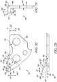
- FIGS. 2A to 2E illustrate various views of the bumper drive link 104 , according to an embodiment of the present invention.
- FIGS. 2A and 2B illustrate perspective views of the bumper drive link 104 .
- the bumper drive link 104 includes a body 202 and a tail 204 such that the tail 204 is located at the top end of the bumper drive link 104 .
- the tail 204 includes a bent portion 206 and a straight portion 208 .
- a free space 210 is present between the bent portion 206 and the straight portion 208 .
- the free space 210 may enable to produce the bent portion 206 without affecting the straight portion 208 , thereby simplifying a manufacturing process of the bumper drive link 106 .
- the free space 210 may be made as small as possible.
- the bumper drive link 104 also includes a tang 212 which may engage with a peripheral groove of the guide bar, a drive sprocket (not shown) and a nose sprocket (as illustrated in FIG. 3 ).
- the tang 212 includes a curved section 214 for one or more purposes, such as, but not limited to, distribution of lubricant, providing an exit for the dust/chips reducing the maintenance needs, and the like.
- the bumper drive link 104 also includes an additional aperture 216 in addition to the apertures 114 for the fasteners. The additional aperture 216 may facilitate distribution of lubricant. Additionally, a notch 218 is also provided to facilitate expulsion of dust/chips and/or distribution of lubricant.
- the bent portion 206 is substantially perpendicular to a plane of the body 202 of the bumper drive link 104 .
- the bent portion 206 includes a top surface 220 which have a quadrilateral shape, as illustrated in FIG. 2A .
- the top surface 220 may have any shape, for example, but not limited to, triangular, pentagonal, or the like within the scope of the present invention.
- the top surface 220 may also be curvilinear.
- a front surface 222 of the bent portion 206 has a substantially parallelogram shape.
- the front surface 222 may be of any shape, for example, but not limited to, rectangular, oval, or the like.
- a height 224 of the bent portion 206 may be lower than a maximum height 226 of the straight portion 208. All the heights are measured with respect to a baseline 228 which is a horizontal line passing through the centres of the apertures 114 .
- the height 224 of the bent portion 206 is about 4.4 mm.
- the maximum height 226 of the straight portion 208 is about 4.7 mm.
- the maximum height 226 of the straight portion 208 may be substantially equal to a height of the depth gauge 118 of the cutting link 106 when the chain 100 is traversing a nose portion of the guide bar (illustrated in FIGS. 3A and 3B ).
- the straight portion 208 also extends over a length 230 such that the straight portion 208 is inclined at an angle 232 with respect to the baseline 224.
- a minimum height 234 of the straight portion 208 is about 3.6 mm while the length 230 of the straight portion 208 is about 4.9 mm.
- the angle 232 is about 13°.
- a length 236 of the free space 210 is about 1.2 mm.
- An angle 238 between the straight portion 208 and an intermediate portion 240 is about 46°.
- An angle 241 between edges 242 and 244 of the bent portion 206 , and the baseline 228 is about 121 °.
- a length 246 of a first side 247 of the top surface 220 is about 2.4 mm.
- the front surface 222 is inclined at an angle 248 with respect to the plane P of the body 202 such that a length 249 of the second side 250 of the top surface 220 is lower than the length 246 of the first side 247 .
- the angle 248 is about 155°.
- the length 249 of the second side 250 is about 1.4 mm.
- a width 251 of the top surface 220 parallel to the plane P lies between is about 2.2 mm.
- a thickness 252 of the bent portion 206 is about 1.3 mm.
- a side length 254 of a bottom surface 256 of the bent portion 206 is about 2.1 mm.
- the side length 254 may be such that the bent portion 206 is at a maximum covering the width of the cutting portion 120 of the trailing cutting link 106 .
- the length 254 is less (most preferably just slightly less) than the width of the cutting portion 120 thus allowing the cutting portion 120 still to cut into wood even when being partially covered by the bent portion 206 .
- a juncture section 260 connects the bent portion 206 of the bumper drive link 104 to the body 202 of the bumper drive link 104 .
- the juncture section 260 is shown to be substantially straight. However, in an alternative embodiment of the present, the juncture section 260 may be inclined at an angle with respect to the plane P of the body 202 , such that the juncture section 260 is bent away from the bent portion 206 . This may reduce the tension applied at a juncture bend 262 , where the bent portion 206 is mounted on the juncture section 260 of the bumper drive link 104. This may safeguard the bent portion 206 against breakage due to stress encountered while performing a cutting operation.
- a thickness of the juncture bend 262 may be more then a thickness 264 of the body 202 . This may further improve the mounting strength of the bent portion 206 on the body 202 .
- a convex projecting member may bulge in the direction of the bent portion 206 . This may shift the tension point from the farther end of the bent portion 206 towards the body 202 of the bumper drive link 104. This may further increase the resistance of the bent portion 206 against breakage.
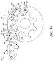
- FIGS. 3A and 3B illustrate a portion of the cutting chain 100 traversing over a nose portion from a straight portion of the guide bar.
- the cutting chain 100 travels over a nose sprocket 302 .
- the tang 212 of the bumper drive link 104 engages with the nose sprocket 302 .
- the bent portion 206 of the bumper drive link 104 extends into the gullet 122 on the cutting link 106 .
- the bent portion 206 is located below the depth gauge 118 of the cutting link 106 while the cutting chain 100 is traversing along the straight portion of the guide bar.
- This arrangement may be such that it may not affect the operation of the chainsaw, while the cutting chain 100 is traversing along the straight portion of the guide bar. Moreover, an additional space 304 is present between the bent portion 206 and the depth gauge 118 facilitates ejection of chips and debris generated during the cutting operation.
- relative spacing between the bumper drive link 104 and the cutting link 106 is such that the bent portion 206 of the bumper drive link 104 aligns with the depth gauge 118 of the cutting link 106 while traversing the nose sprocket 302. Further, the bent portion 206 may form a continuous edge with the depth gauge 118 of the cutting link 106 . Thus, an effective area of the depth gauge 118 increases and this may provide improved depth of cut control, thereby reducing kickback. Further, the bent portion 206 extends above the depth gauge 118 when the bent portion 206 of the bumper drive link 104 aligns with the depth gauge 118 of the cutting link 106 . Moreover, the free space 210 between the bent portion 206 and the straight portion 208 is covered by the depth gauge 118 .
- the height of the straight portion 208 also becomes substantially to the height of the depth gauge 118 such that the straight portion 208 laterally aligns with the depth gauge 118 while traversing the nose sprocket 302 .
- the effective area of the depth gauge 118 further increases, thereby reducing the occurrence of kickbacks. It may also be apparent from FIGS. 3A and 3B that the bent portion 206 extends above the cutting portion 120 of the cutting link 106 while traversing the nose sprocket 302 .
Landscapes
- Life Sciences & Earth Sciences (AREA)
- Engineering & Computer Science (AREA)
- Mechanical Engineering (AREA)
- Wood Science & Technology (AREA)
- Forests & Forestry (AREA)
- Sawing (AREA)
Claims (12)
- Schneidkette (100), die in eine Schnittrichtung (124) beweglich ist, wobei die Schneidkette (100) umfasst,
zumindest ein Schneidglied (106) umfassend einen Schneidabschnitt (120), eine Tiefenlehre (118) und einen Zwischenraum (122) zwischen dem Schneidabschnitt (120) und der Tiefenlehre (118); und
zumindest ein Dämpfungs-Antriebsglied (104), das dem Schneidglied (106) in der Schneidrichtung (124) unmittelbar vorangeht und schwenkbar mit dem Schneidglied (106) verbunden ist, wobei das Dämpfungs-Antriebsglied (104) einen Schwanz (204) und einen Körper (201) umfasst;
dadurch gekennzeichnet, dass
der Schwanz (204) des Dämpfungs-Antriebsgliedes (104) einen gebogenen Abschnitt (206) und einen geraden Abschnitt (208) umfasst, wobei der gebogene Abschnitt (206) im Wesentlichen senkrecht auf eine Ebene (P) des Körpers (202) des Dämpfungs-Antriebsgliedes (104) orientiert ist; und
der gebogene Abschnitt (206) sich in den Zwischenraum (122) zwischen dem Schneidabschnitt (120) und der Tiefenlehre (118) des Schneidgliedes (106) erstreckt. - Schneidkette (100) nach Anspruch 1, wobei eine Höhe (224) des gebogenen Abschnitts (206) geringer als eine Höhe (226) des geraden Abschnitts (208) ist.
- Schneidkette (100) nach Anspruch 1, wobei der gebogene Abschnitt (206) des Dämpfungs-Antriebsgliedes (104) unter der Tiefenlehre (118) des Schneidgliedes (106) bleibt, während er über einen geraden Abschnitt einer Führungsschiene läuft.
- Schneidkette (100) nach Anspruch 1, wobei der gebogene Abschnitt (206) des Dämpfungs-Antriebsgliedes (104) sich mit der Tiefenlehre (118) ausrichtet, um eine im Wesentlichen durchgehende Kante zu bilden, während er über einen Nasenabschnitt der Führungsschiene läuft.
- Schneidkette (100) nach Anspruch 1, wobei der gerade Abschnitt (208) sich mit der Tiefenlehre (118) des Schneidgliedes (106) ausrichtet, während er über einen Nasenabschnitt der Führungsschiene läuft.
- Schneidkette (100) nach Anspruch 1, wobei ein freier Zwischenraum (210) zwischen dem gebogenen Abschnitt (206) und dem geraden Abschnitt (208) des Schwanzes (204) vorgesehen ist.
- Schneidkette (100) nach Anspruch 6, wobei der freie Zwischenraum (210) von der Tiefenlehre (118) des Schneidgliedes (106) abgedeckt wird, während er über einen Nasenabschnitt einer Führungsschiene läuft.
- Schneidkette (100) nach Anspruch 1, wobei der gebogene Abschnitt (206) sich über den Schneidabschnitt (120) des Schneidgliedes (106) erstreckt, während er über einen Nasenabschnitt der Führungsschiene läuft.
- Schneidkette (100) nach Anspruch 1, wobei die Schneidkette (100) des Weiteren zumindest ein Antriebsglied (108) umfasst.
- Dämpfungs-Antriebsglied (104) für eine Schneidkette (100), wobei das Dämpfungs-Antriebsglied (104) umfasst:einen Körper (202) mit einer Ebene (P); undeinen Schwanz (204), der einen gebogenen Abschnitt (206) und einen geraden Abschnitt (208) umfasst;wobei der gebogene Abschnitt (206) im Wesentlichen senkrecht auf die Ebene (P) des Körpers (202) des Dämpfungs-Antriebsgliedes ausgerichtet ist, dadurch gekennzeichnet, dass die Höhe (224) des gebogenen Abschnitts (206) geringer als eine Höhe (226) des geraden Abschnitts (208) ist.
- Dämpfungs-Antriebsglied (104) nach Anspruch 10, wobei ein freier Zwischenraum (210) zwischen dem gebogenen Abschnitt (206) und dem geraden Abschnitt (208) des Schwanzes (204) vorgesehen ist.
- Schneidkette (106) nach einem der Ansprüche 1 bis 9, wobei die Schneidkette (106) dazu geeignet ist, mit einer Kettensäge verwendet zu werden.
Applications Claiming Priority (1)
| Application Number | Priority Date | Filing Date | Title |
|---|---|---|---|
| PCT/EP2011/050398 WO2012095177A1 (en) | 2011-01-13 | 2011-01-13 | Kickback reducing chain link |
Publications (2)
| Publication Number | Publication Date |
|---|---|
| EP2663432A1 EP2663432A1 (de) | 2013-11-20 |
| EP2663432B1 true EP2663432B1 (de) | 2017-08-16 |
Family
ID=44483872
Family Applications (1)
| Application Number | Title | Priority Date | Filing Date |
|---|---|---|---|
| EP11701044.7A Active EP2663432B1 (de) | 2011-01-13 | 2011-01-13 | Rückschlagreduzierendes kettenglied und ketten |
Country Status (4)
| Country | Link |
|---|---|
| US (1) | US9561600B2 (de) |
| EP (1) | EP2663432B1 (de) |
| RU (1) | RU2562952C2 (de) |
| WO (1) | WO2012095177A1 (de) |
Cited By (2)
| Publication number | Priority date | Publication date | Assignee | Title |
|---|---|---|---|---|
| US20160221209A1 (en) * | 2015-01-30 | 2016-08-04 | Blount, Inc. | Tie rivet for saw chain |
| US11247363B2 (en) | 2018-01-23 | 2022-02-15 | Oregon Tool, Inc. | Saw chain presets |
Families Citing this family (8)
| Publication number | Priority date | Publication date | Assignee | Title |
|---|---|---|---|---|
| DE102012215460A1 (de) * | 2012-08-31 | 2014-03-06 | Robert Bosch Gmbh | Schneidstrangsegment |
| US9027451B2 (en) | 2012-10-02 | 2015-05-12 | Blount, Inc. | Dresser drive link for saw chain |
| US9757808B2 (en) * | 2013-03-14 | 2017-09-12 | Blount, Inc. | Formed wire tie strap with integrated rivet for a saw chain |
| AT515667B1 (de) * | 2014-05-26 | 2015-11-15 | Prinz Gmbh & Co Kg | Sägekette und Verfahren zur Herstellung eines Verbindungsgliedes für eine Sägekette |
| EP3397434B1 (de) | 2016-01-13 | 2022-09-28 | Oregon Tool, Inc. | Sägekette mit einem treibglied mit zwei überdimensionierten nietlöchern |
| USD1012649S1 (en) * | 2022-05-18 | 2024-01-30 | Zhejiang Trilink Huihuang Co., Ltd | Saw chain |
| USD1026596S1 (en) * | 2022-06-02 | 2024-05-14 | Zhuji Bolin Tools Co., Ltd. | Saw chain |
| USD1116690S1 (en) * | 2024-10-03 | 2026-03-10 | Oregon Tool, Inc. | Cutting elements for chainsaw chain |
Family Cites Families (25)
| Publication number | Priority date | Publication date | Assignee | Title |
|---|---|---|---|---|
| US3545508A (en) * | 1968-02-05 | 1970-12-08 | Omark Industries Inc | Dual element top sharpening saw chains |
| CA1109370A (en) * | 1978-11-30 | 1981-09-22 | Windsor Machine Company Limited | Saw chain |
| DE3002115C2 (de) * | 1980-01-22 | 1982-12-02 | Fa. Andreas Stihl, 7050 Waiblingen | Sägekette für Motorsägen |
| DE3326643A1 (de) * | 1983-07-23 | 1985-01-31 | Fa. Andreas Stihl, 7050 Waiblingen | Saegekette fuer eine kettensaege |
| US4604932A (en) * | 1983-10-24 | 1986-08-12 | Omark Industries, Inc. | Safety chain for chain saws |
| US4590836A (en) * | 1983-11-17 | 1986-05-27 | Omark Industries, Inc. | Safety chain for chain saws |
| US4608901A (en) * | 1983-12-19 | 1986-09-02 | Omark Industries, Inc. | Safety chain for chain saws |
| US4581968A (en) * | 1984-04-13 | 1986-04-15 | Omark Industries, Inc. | Saw chain with improved cutting depth control |
| US4625610A (en) * | 1985-11-04 | 1986-12-02 | Omark Industries, Inc. | Cutting chain having automatic sharpening |
| US4813323A (en) * | 1987-08-18 | 1989-03-21 | Blount, Inc. | Chain link with folded over connecting portions |
| US4873903A (en) * | 1988-07-07 | 1989-10-17 | Blount, Inc. | Saw chain with wear link |
| US5666871A (en) * | 1994-11-14 | 1997-09-16 | Blount, Inc. | Saw chain cutter with bent over depth gauge |
| US5651938A (en) * | 1995-05-01 | 1997-07-29 | Blount, Inc. | High strength steel composition having enhanced low temperature toughness |
| US6058825A (en) * | 1997-03-06 | 2000-05-09 | Blout, Inc. | Depth gauge for cutter |
| DE10216529A1 (de) * | 2002-04-15 | 2003-10-30 | Stihl Maschf Andreas | Sägekette |
| DE10221944A1 (de) * | 2002-05-17 | 2003-11-27 | Stihl Maschf Andreas | Sägekette |
| US6748840B2 (en) * | 2002-08-07 | 2004-06-15 | Blount, Inc. | Saw chain having drive link with guard feature |
| US20080072733A1 (en) * | 2004-12-01 | 2008-03-27 | Matthias Schulz | Saw Chain for A Power Chain Saw |
| US7516688B2 (en) * | 2005-04-29 | 2009-04-14 | Unifire Power Blowers, Inc. | Saw chains having hardened cutting elements |
| US20080011144A1 (en) * | 2006-07-13 | 2008-01-17 | Blount, Inc., A Limited Liability Company Of Delaware | Saw chain having multiple drive link configurations |
| US7637192B2 (en) | 2006-10-26 | 2009-12-29 | Blount, Inc. | Saw chain drive link with tail |
| US8136436B2 (en) * | 2006-11-15 | 2012-03-20 | Blount, Inc. | Saw chain link with offset footprint |
| SE532991C2 (sv) * | 2008-09-17 | 2010-06-01 | Komatsu Forest Ab | Förfarande och anordning vid sågkedja |
| US8256335B1 (en) * | 2009-05-21 | 2012-09-04 | Wyatt Canon | Bi-directional chainsaw chain |
| DE102012010978A1 (de) * | 2012-05-31 | 2013-12-05 | Andreas Stihl Ag & Co. Kg | "Schneidkette zum Schneiden von mineralischen oder metallischen Werkstoffen" |
-
2011
- 2011-01-13 WO PCT/EP2011/050398 patent/WO2012095177A1/en not_active Ceased
- 2011-01-13 EP EP11701044.7A patent/EP2663432B1/de active Active
- 2011-01-13 RU RU2013137761/13A patent/RU2562952C2/ru not_active IP Right Cessation
- 2011-01-13 US US13/979,445 patent/US9561600B2/en active Active
Non-Patent Citations (1)
| Title |
|---|
| None * |
Cited By (3)
| Publication number | Priority date | Publication date | Assignee | Title |
|---|---|---|---|---|
| US20160221209A1 (en) * | 2015-01-30 | 2016-08-04 | Blount, Inc. | Tie rivet for saw chain |
| US10406715B2 (en) * | 2015-01-30 | 2019-09-10 | Blount, Inc. | Tie rivet for saw chain |
| US11247363B2 (en) | 2018-01-23 | 2022-02-15 | Oregon Tool, Inc. | Saw chain presets |
Also Published As
| Publication number | Publication date |
|---|---|
| US20130291702A1 (en) | 2013-11-07 |
| EP2663432A1 (de) | 2013-11-20 |
| US9561600B2 (en) | 2017-02-07 |
| RU2013137761A (ru) | 2015-02-20 |
| WO2012095177A1 (en) | 2012-07-19 |
| RU2562952C2 (ru) | 2015-09-10 |
Similar Documents
| Publication | Publication Date | Title |
|---|---|---|
| EP2663432B1 (de) | Rückschlagreduzierendes kettenglied und ketten | |
| CA2697300C (en) | Aggregate cutting saw chain | |
| FI73618C (fi) | Saekerhetssaogkedja. | |
| JPH0345761Y2 (de) | ||
| CN101588887B (zh) | 具有尾部的锯链传动链节 | |
| US8136436B2 (en) | Saw chain link with offset footprint | |
| CA1272664A (en) | Saw chain | |
| US12365109B2 (en) | Saw chain link with one or more oversized rivet holes | |
| EP1388399A1 (de) | Sägekette mit Sicherheitsmerkmal aufweisendem Treibglied | |
| EP0251493B1 (de) | Schwingungsgedämpfte Sägekette | |
| AU2008361775B2 (en) | Method and arrangement for a sawchain | |
| US20180326610A1 (en) | High efficiency saw chain | |
| CA2236346C (en) | Cutting member for the saw chain of a motor chainsaw | |
| US11090741B2 (en) | High efficiency saw chain | |
| US20240066744A1 (en) | Chainsaw chains | |
| US20080110316A1 (en) | Saw chain cutting link with taper | |
| US9718204B2 (en) | Chain-type cutting assembly | |
| RU49752U1 (ru) | Пильная цепь | |
| WO2016086987A1 (en) | Guiding device for a power driven saw |
Legal Events
| Date | Code | Title | Description |
|---|---|---|---|
| PUAI | Public reference made under article 153(3) epc to a published international application that has entered the european phase |
Free format text: ORIGINAL CODE: 0009012 |
|
| 17P | Request for examination filed |
Effective date: 20130705 |
|
| AK | Designated contracting states |
Kind code of ref document: A1 Designated state(s): AL AT BE BG CH CY CZ DE DK EE ES FI FR GB GR HR HU IE IS IT LI LT LU LV MC MK MT NL NO PL PT RO RS SE SI SK SM TR |
|
| DAX | Request for extension of the european patent (deleted) | ||
| GRAP | Despatch of communication of intention to grant a patent |
Free format text: ORIGINAL CODE: EPIDOSNIGR1 |
|
| INTG | Intention to grant announced |
Effective date: 20170518 |
|
| GRAS | Grant fee paid |
Free format text: ORIGINAL CODE: EPIDOSNIGR3 |
|
| GRAA | (expected) grant |
Free format text: ORIGINAL CODE: 0009210 |
|
| AK | Designated contracting states |
Kind code of ref document: B1 Designated state(s): AL AT BE BG CH CY CZ DE DK EE ES FI FR GB GR HR HU IE IS IT LI LT LU LV MC MK MT NL NO PL PT RO RS SE SI SK SM TR |
|
| REG | Reference to a national code |
Ref country code: GB Ref legal event code: FG4D |
|
| REG | Reference to a national code |
Ref country code: CH Ref legal event code: EP |
|
| REG | Reference to a national code |
Ref country code: IE Ref legal event code: FG4D |
|
| REG | Reference to a national code |
Ref country code: AT Ref legal event code: REF Ref document number: 918614 Country of ref document: AT Kind code of ref document: T Effective date: 20170915 |
|
| REG | Reference to a national code |
Ref country code: DE Ref legal event code: R096 Ref document number: 602011040579 Country of ref document: DE |
|
| REG | Reference to a national code |
Ref country code: NL Ref legal event code: MP Effective date: 20170816 |
|
| REG | Reference to a national code |
Ref country code: LT Ref legal event code: MG4D |
|
| REG | Reference to a national code |
Ref country code: AT Ref legal event code: MK05 Ref document number: 918614 Country of ref document: AT Kind code of ref document: T Effective date: 20170816 |
|
| PG25 | Lapsed in a contracting state [announced via postgrant information from national office to epo] |
Ref country code: SE Free format text: LAPSE BECAUSE OF FAILURE TO SUBMIT A TRANSLATION OF THE DESCRIPTION OR TO PAY THE FEE WITHIN THE PRESCRIBED TIME-LIMIT Effective date: 20170816 Ref country code: NL Free format text: LAPSE BECAUSE OF FAILURE TO SUBMIT A TRANSLATION OF THE DESCRIPTION OR TO PAY THE FEE WITHIN THE PRESCRIBED TIME-LIMIT Effective date: 20170816 Ref country code: LT Free format text: LAPSE BECAUSE OF FAILURE TO SUBMIT A TRANSLATION OF THE DESCRIPTION OR TO PAY THE FEE WITHIN THE PRESCRIBED TIME-LIMIT Effective date: 20170816 Ref country code: FI Free format text: LAPSE BECAUSE OF FAILURE TO SUBMIT A TRANSLATION OF THE DESCRIPTION OR TO PAY THE FEE WITHIN THE PRESCRIBED TIME-LIMIT Effective date: 20170816 Ref country code: AT Free format text: LAPSE BECAUSE OF FAILURE TO SUBMIT A TRANSLATION OF THE DESCRIPTION OR TO PAY THE FEE WITHIN THE PRESCRIBED TIME-LIMIT Effective date: 20170816 Ref country code: NO Free format text: LAPSE BECAUSE OF FAILURE TO SUBMIT A TRANSLATION OF THE DESCRIPTION OR TO PAY THE FEE WITHIN THE PRESCRIBED TIME-LIMIT Effective date: 20171116 |
|
| PG25 | Lapsed in a contracting state [announced via postgrant information from national office to epo] |
Ref country code: ES Free format text: LAPSE BECAUSE OF FAILURE TO SUBMIT A TRANSLATION OF THE DESCRIPTION OR TO PAY THE FEE WITHIN THE PRESCRIBED TIME-LIMIT Effective date: 20170816 Ref country code: LV Free format text: LAPSE BECAUSE OF FAILURE TO SUBMIT A TRANSLATION OF THE DESCRIPTION OR TO PAY THE FEE WITHIN THE PRESCRIBED TIME-LIMIT Effective date: 20170816 Ref country code: GR Free format text: LAPSE BECAUSE OF FAILURE TO SUBMIT A TRANSLATION OF THE DESCRIPTION OR TO PAY THE FEE WITHIN THE PRESCRIBED TIME-LIMIT Effective date: 20171117 Ref country code: BG Free format text: LAPSE BECAUSE OF FAILURE TO SUBMIT A TRANSLATION OF THE DESCRIPTION OR TO PAY THE FEE WITHIN THE PRESCRIBED TIME-LIMIT Effective date: 20171116 Ref country code: IS Free format text: LAPSE BECAUSE OF FAILURE TO SUBMIT A TRANSLATION OF THE DESCRIPTION OR TO PAY THE FEE WITHIN THE PRESCRIBED TIME-LIMIT Effective date: 20171216 Ref country code: RS Free format text: LAPSE BECAUSE OF FAILURE TO SUBMIT A TRANSLATION OF THE DESCRIPTION OR TO PAY THE FEE WITHIN THE PRESCRIBED TIME-LIMIT Effective date: 20170816 Ref country code: PL Free format text: LAPSE BECAUSE OF FAILURE TO SUBMIT A TRANSLATION OF THE DESCRIPTION OR TO PAY THE FEE WITHIN THE PRESCRIBED TIME-LIMIT Effective date: 20170816 |
|
| PG25 | Lapsed in a contracting state [announced via postgrant information from national office to epo] |
Ref country code: RO Free format text: LAPSE BECAUSE OF FAILURE TO SUBMIT A TRANSLATION OF THE DESCRIPTION OR TO PAY THE FEE WITHIN THE PRESCRIBED TIME-LIMIT Effective date: 20170816 Ref country code: CZ Free format text: LAPSE BECAUSE OF FAILURE TO SUBMIT A TRANSLATION OF THE DESCRIPTION OR TO PAY THE FEE WITHIN THE PRESCRIBED TIME-LIMIT Effective date: 20170816 Ref country code: DK Free format text: LAPSE BECAUSE OF FAILURE TO SUBMIT A TRANSLATION OF THE DESCRIPTION OR TO PAY THE FEE WITHIN THE PRESCRIBED TIME-LIMIT Effective date: 20170816 |
|
| REG | Reference to a national code |
Ref country code: DE Ref legal event code: R097 Ref document number: 602011040579 Country of ref document: DE |
|
| PG25 | Lapsed in a contracting state [announced via postgrant information from national office to epo] |
Ref country code: EE Free format text: LAPSE BECAUSE OF FAILURE TO SUBMIT A TRANSLATION OF THE DESCRIPTION OR TO PAY THE FEE WITHIN THE PRESCRIBED TIME-LIMIT Effective date: 20170816 Ref country code: SM Free format text: LAPSE BECAUSE OF FAILURE TO SUBMIT A TRANSLATION OF THE DESCRIPTION OR TO PAY THE FEE WITHIN THE PRESCRIBED TIME-LIMIT Effective date: 20170816 Ref country code: SK Free format text: LAPSE BECAUSE OF FAILURE TO SUBMIT A TRANSLATION OF THE DESCRIPTION OR TO PAY THE FEE WITHIN THE PRESCRIBED TIME-LIMIT Effective date: 20170816 Ref country code: IT Free format text: LAPSE BECAUSE OF FAILURE TO SUBMIT A TRANSLATION OF THE DESCRIPTION OR TO PAY THE FEE WITHIN THE PRESCRIBED TIME-LIMIT Effective date: 20170816 |
|
| PLBE | No opposition filed within time limit |
Free format text: ORIGINAL CODE: 0009261 |
|
| STAA | Information on the status of an ep patent application or granted ep patent |
Free format text: STATUS: NO OPPOSITION FILED WITHIN TIME LIMIT |
|
| 26N | No opposition filed |
Effective date: 20180517 |
|
| PG25 | Lapsed in a contracting state [announced via postgrant information from national office to epo] |
Ref country code: SI Free format text: LAPSE BECAUSE OF FAILURE TO SUBMIT A TRANSLATION OF THE DESCRIPTION OR TO PAY THE FEE WITHIN THE PRESCRIBED TIME-LIMIT Effective date: 20170816 |
|
| REG | Reference to a national code |
Ref country code: CH Ref legal event code: PL |
|
| GBPC | Gb: european patent ceased through non-payment of renewal fee |
Effective date: 20180113 |
|
| PG25 | Lapsed in a contracting state [announced via postgrant information from national office to epo] |
Ref country code: LU Free format text: LAPSE BECAUSE OF NON-PAYMENT OF DUE FEES Effective date: 20180113 Ref country code: FR Free format text: LAPSE BECAUSE OF NON-PAYMENT OF DUE FEES Effective date: 20180131 |
|
| REG | Reference to a national code |
Ref country code: IE Ref legal event code: MM4A |
|
| REG | Reference to a national code |
Ref country code: FR Ref legal event code: ST Effective date: 20180928 |
|
| REG | Reference to a national code |
Ref country code: BE Ref legal event code: MM Effective date: 20180131 |
|
| PG25 | Lapsed in a contracting state [announced via postgrant information from national office to epo] |
Ref country code: GB Free format text: LAPSE BECAUSE OF NON-PAYMENT OF DUE FEES Effective date: 20180113 Ref country code: CH Free format text: LAPSE BECAUSE OF NON-PAYMENT OF DUE FEES Effective date: 20180131 Ref country code: LI Free format text: LAPSE BECAUSE OF NON-PAYMENT OF DUE FEES Effective date: 20180131 Ref country code: BE Free format text: LAPSE BECAUSE OF NON-PAYMENT OF DUE FEES Effective date: 20180131 |
|
| PG25 | Lapsed in a contracting state [announced via postgrant information from national office to epo] |
Ref country code: IE Free format text: LAPSE BECAUSE OF NON-PAYMENT OF DUE FEES Effective date: 20180113 |
|
| PG25 | Lapsed in a contracting state [announced via postgrant information from national office to epo] |
Ref country code: MC Free format text: LAPSE BECAUSE OF FAILURE TO SUBMIT A TRANSLATION OF THE DESCRIPTION OR TO PAY THE FEE WITHIN THE PRESCRIBED TIME-LIMIT Effective date: 20170816 |
|
| PG25 | Lapsed in a contracting state [announced via postgrant information from national office to epo] |
Ref country code: MT Free format text: LAPSE BECAUSE OF NON-PAYMENT OF DUE FEES Effective date: 20180113 |
|
| PG25 | Lapsed in a contracting state [announced via postgrant information from national office to epo] |
Ref country code: TR Free format text: LAPSE BECAUSE OF FAILURE TO SUBMIT A TRANSLATION OF THE DESCRIPTION OR TO PAY THE FEE WITHIN THE PRESCRIBED TIME-LIMIT Effective date: 20170816 |
|
| PG25 | Lapsed in a contracting state [announced via postgrant information from national office to epo] |
Ref country code: HU Free format text: LAPSE BECAUSE OF FAILURE TO SUBMIT A TRANSLATION OF THE DESCRIPTION OR TO PAY THE FEE WITHIN THE PRESCRIBED TIME-LIMIT; INVALID AB INITIO Effective date: 20110113 Ref country code: PT Free format text: LAPSE BECAUSE OF FAILURE TO SUBMIT A TRANSLATION OF THE DESCRIPTION OR TO PAY THE FEE WITHIN THE PRESCRIBED TIME-LIMIT Effective date: 20170816 |
|
| PG25 | Lapsed in a contracting state [announced via postgrant information from national office to epo] |
Ref country code: CY Free format text: LAPSE BECAUSE OF FAILURE TO SUBMIT A TRANSLATION OF THE DESCRIPTION OR TO PAY THE FEE WITHIN THE PRESCRIBED TIME-LIMIT Effective date: 20170816 Ref country code: HR Free format text: LAPSE BECAUSE OF FAILURE TO SUBMIT A TRANSLATION OF THE DESCRIPTION OR TO PAY THE FEE WITHIN THE PRESCRIBED TIME-LIMIT Effective date: 20170816 Ref country code: MK Free format text: LAPSE BECAUSE OF NON-PAYMENT OF DUE FEES Effective date: 20170816 |
|
| PG25 | Lapsed in a contracting state [announced via postgrant information from national office to epo] |
Ref country code: AL Free format text: LAPSE BECAUSE OF FAILURE TO SUBMIT A TRANSLATION OF THE DESCRIPTION OR TO PAY THE FEE WITHIN THE PRESCRIBED TIME-LIMIT Effective date: 20170816 |
|
| P01 | Opt-out of the competence of the unified patent court (upc) registered |
Effective date: 20230419 |
|
| PGFP | Annual fee paid to national office [announced via postgrant information from national office to epo] |
Ref country code: DE Payment date: 20251209 Year of fee payment: 16 |