EP2663836B1 - Appareil de mesure ayant une fonctionnalité de ciblage dynamique et procédé associé - Google Patents
Appareil de mesure ayant une fonctionnalité de ciblage dynamique et procédé associé Download PDFInfo
- Publication number
- EP2663836B1 EP2663836B1 EP12701084.1A EP12701084A EP2663836B1 EP 2663836 B1 EP2663836 B1 EP 2663836B1 EP 12701084 A EP12701084 A EP 12701084A EP 2663836 B1 EP2663836 B1 EP 2663836B1
- Authority
- EP
- European Patent Office
- Prior art keywords
- display point
- display
- alignment
- anchor
- point
- Prior art date
- Legal status (The legal status is an assumption and is not a legal conclusion. Google has not performed a legal analysis and makes no representation as to the accuracy of the status listed.)
- Not-in-force
Links
- 238000000034 method Methods 0.000 title claims description 25
- 238000010276 construction Methods 0.000 claims description 20
- 238000011156 evaluation Methods 0.000 claims description 20
- 230000001419 dependent effect Effects 0.000 claims description 4
- 238000004590 computer program Methods 0.000 claims description 3
- 238000012545 processing Methods 0.000 claims description 3
- 230000008685 targeting Effects 0.000 description 54
- 238000005259 measurement Methods 0.000 description 7
- 238000003384 imaging method Methods 0.000 description 3
- 230000005693 optoelectronics Effects 0.000 description 3
- 238000012883 sequential measurement Methods 0.000 description 3
- 238000013461 design Methods 0.000 description 2
- 239000003550 marker Substances 0.000 description 2
- 230000003213 activating effect Effects 0.000 description 1
- 238000013459 approach Methods 0.000 description 1
- 238000004891 communication Methods 0.000 description 1
- 238000011161 development Methods 0.000 description 1
- 230000018109 developmental process Effects 0.000 description 1
- 230000005484 gravity Effects 0.000 description 1
- 238000009434 installation Methods 0.000 description 1
- 230000003287 optical effect Effects 0.000 description 1
- 239000007787 solid Substances 0.000 description 1
- 210000002023 somite Anatomy 0.000 description 1
- 238000004441 surface measurement Methods 0.000 description 1
- 238000012546 transfer Methods 0.000 description 1
Images

Classifications
-
- G—PHYSICS
- G01—MEASURING; TESTING
- G01C—MEASURING DISTANCES, LEVELS OR BEARINGS; SURVEYING; NAVIGATION; GYROSCOPIC INSTRUMENTS; PHOTOGRAMMETRY OR VIDEOGRAMMETRY
- G01C11/00—Photogrammetry or videogrammetry, e.g. stereogrammetry; Photographic surveying
-
- G—PHYSICS
- G01—MEASURING; TESTING
- G01C—MEASURING DISTANCES, LEVELS OR BEARINGS; SURVEYING; NAVIGATION; GYROSCOPIC INSTRUMENTS; PHOTOGRAMMETRY OR VIDEOGRAMMETRY
- G01C15/00—Surveying instruments or accessories not provided for in groups G01C1/00 - G01C13/00
-
- G—PHYSICS
- G01—MEASURING; TESTING
- G01C—MEASURING DISTANCES, LEVELS OR BEARINGS; SURVEYING; NAVIGATION; GYROSCOPIC INSTRUMENTS; PHOTOGRAMMETRY OR VIDEOGRAMMETRY
- G01C15/00—Surveying instruments or accessories not provided for in groups G01C1/00 - G01C13/00
- G01C15/002—Active optical surveying means
Definitions
- the invention relates to a construction measuring device for measuring and / or marking spatial points of surfaces of a construction - in particular interiors of buildings - according to the preamble of claim 1 and an associated method for manually controlled alignment of a target unit of a surveying device based on a marking of display points on a display the preamble of claim 10 and an associated computer program product according to the preamble of claim 15.
- the prior art discloses simple construction surveying apparatus with a targeting device by means of which a point of space, e.g. a vertex, is targeted, and then the targeting direction is then manually moved to a next spatial point to be measured, e.g. another corner, is changed.
- a point of space e.g. a vertex
- the DE 196 48 626 For example, a method and apparatus for surface measurement with a laser range finder with a laser transmitter and a laser receiver is disclosed.
- the laser rangefinder is mounted on a tripod.
- the device further comprises a tilting and rotating device for alignment and direction measurement, a riflescope and an electronic evaluation unit for angle data, distance data acquisition and data transfer to a computer.
- the device For the measurement of a room, the device is positioned at a central point of the room, from which all spatial and / or surface areas to be detected can be targeted and acted upon by the laser beam.
- the space points to be surveyed are each individually sighted, possibly at a greater distance with the support of observation by a telescopic sight.
- An automated sequential measurement of several points in space, to be compared, for example, with a scan, is described in DE 196 48 626 not revealed.
- a similar device and associated surveying method are described in the DE 44 43 413 , the supplementary disclosure DE 195 45 589 and the WO 96/18083 which is the priority of DE 44 43 413 claims disclosed.
- a method and a device for measuring and marking on distanced lines, surfaces or in at least partially closed spaces are described.
- One or more relevant spatial points are measured after every two solid angles and the distance from a reference location by means of a gimbal-mounted laser distance measuring device.
- the laser distance measuring device is pivotable about two mutually perpendicular axes, which are equipped with protractors.
- spatial points to be measured are controlled manually, marker values are calculated from the survey data, based on a predetermined relative relationship between measurement and marking, which are then approached independently by the measuring and marking device.
- EP 1 733 185 discloses a device and a method with which specifically measured edges on a polygonal, otherwise flat surface accurately should be. However, no automated sequential measurement of multiple space points is disclosed.
- Known construction surveying equipment typically includes a base, a base rotatably supported at the base about a rotation axis, and a targeting unit pivotally mounted with a laser beam for emitting a laser beam and an imaging detector equipped with an alignment display functionality for indicating alignment of the targeting unit, for example a point of space as a target point, and a distance determination detector for providing distance measurement functionality.
- the orientation display functionality may be, for example, a crosshair in the viewfinder of a camera as an imaging detector.
- Modern, automated construction surveying devices further include rotary actuators, which make the upper part or target unit driven by motor, protractor and, if necessary inclination sensors for determining the spatial orientation of the target unit, and an evaluation and control unit, which with the laser source, the distance determination detector and the protractors and optionally tilt sensors is connected.
- the evaluation and control unit is equipped, for example, with a display with input means for inputting control commands of a user on the display and for displaying an image of the imaging detector or the camera on the display, wherein the alignment of the targeting unit by means of Alignment display functionality can be displayed on the display eg by means of crossfading.
- Functionalities are known in which the input means are formed on the display as four large area arrows whose marking or touch allows a user to change the orientation of the targeting unit in the horizontal or vertical direction. A change in orientation in any direction, not only in the horizontal or vertical direction, however, based on such functionality can be time consuming and difficult to handle and not very intuitive to use.
- the object of the invention is to provide a surveying device and an associated method for measuring and / or marking spatial points on surfaces of a construction with improved functionality for changing the orientation of the targeting unit, which offers a user an increased ease of use and in particular based on which the user faster desired target point in space - at least roughly - can drive.
- the invention relates to a surveying device (in particular construction measuring device) for measuring and / or marking points in space on surfaces of a construction, in particular interior spaces of buildings.
- the device comprises a base and a targeting unit which can rotate and swivel relative to the base and provides a distance measuring functionality with a laser source designed to emit a laser beam in the direction of a target axis and a laser light detector and with an integrated digital camera aligned in the direction of the target axis.
- an upper part rotatably mounted on the base about an axis of rotation within an angular range of an azimuthal or horizontal angle is provided, and the targeting unit is pivotally mounted on the upper part about a pivot axis within an angular range of elevation and vertical angle.
- the inventive surveying device further comprises an evaluation and control unit, a display for displaying an image of the camera and input means for marking display points on the display (so that control commands can be entered by a user, for example).
- the input means are in particular designed such that - with a certain resolution - points on the entire display (ie on the entire display surface) are markable (eg analogous to the computer mouse, a touch screen, a track ball, etc.).
- the resolution of markable display points can in fact coincide with the screen resolution (screen pixel) in particular, but the resolution of markable display points can also be lower than the resolution of pixels that can actually be displayed on the screen.
- the particular point of interest currently targeted with the target axis can be seen in the operating state on the display in the picture be imaged (in a target pixel), in particular indexed using a crosshair.
- the device comprises a first and second rotary drive, which make the upper part or the targeting unit drivable or alignable in an azimuth and an elevation angle.
- a spatial orientation of the targeting unit relative to the base is via two protractors for determining the horizontal and vertical orientation, i. of the azimuth and elevation angles, detectable.
- the evaluation and control unit is connected to the laser source, the laser light detector and the protractors to assign a detected distance to a corresponding orientation (i.e., detected azimuth and elevation angles) and thus to determine coordinates for space points.
- the evaluation and control unit is also connected to the camera.
- the device - in particular integrated in the base of the device - optionally be equipped with inclination sensor means whose measurement data are then also transmitted to the evaluation and control unit.
- the current orientation of the device ie, a slope of the base
- the inclination sensor means may be configured to determine the inclination to the gravitational field (or to a horizontal plane perpendicular to the gravitational field) in two directions (ie about two axes).
- two single-axis tilt sensors or a two-axis tilt sensor such as opto-electronic level sensors, an optoelectronic oil pot or an optoelectronic circular level.
- An example of such an oil pan inclination sensor, with which the inclination can determine at least about two axes, is detailed in the European patent application with the application file number EP 10173726.0 described.
- that display point can be defined as the anchor display point, which represents the position of the target axis in the image and thus a target pixel, in particular where it is indexed on the display by a crosshairs displayed superimposed on the image.
- the user himself can define any desired display point as the anchor display point.
- the functionality can be configured such that it can be activated by marking the display pixel or the crosshairs representing the target pixel.
- the display is designed as a touch-sensitive touch screen, on which display dots can be marked on the entire surface of the display by touch, and thus the input means are provided.
- the change of the alignment of the targeting unit in the horizontal and vertical direction takes place in accordance with the direction from the defined central anchor display point to the respectively currently marked pixel. It is preferred that the orientation change occur at a maximum velocity at a maximum distance of the marked pixel from the anchor point and the rate of alignment change is zero, i. E. no change of direction occurs when the first and second marked pixels coincide, i. are identical.
- the display is divided into virtual sectors by concentric circular lines around the anchor display point (such as the crosshair center) and radial lines intersecting these circle lines originating from the anchor display point.
- the sectors correspond to digitized differences for a change in the orientation of the targeting unit from the first targeted spatial point to other spatial points in the horizontal and vertical directions, and the change in the orientation of the targeting unit is made as long as the other pixel in a sector is continuously marked.
- the concentric circle lines around the anchor display point correspond to different distances to the currently marked pixel, whereby speed levels are set for the direction change of the target unit, wherein outer circle lines correspond to maximum speed levels, so that the change in direction when marking outer pixels after activating the dynamic targeting functionality, with a fixed maximum speed, as long as that other pixel is marked.
- the distance measurement functionality includes an electronic distance meter.
- the virtual network for a user visible on the display can be displayed superimposed on a current camera image.
- display point be defined as the anchor display point, which represents the position of the target axis in the image and thus a target pixel, in particular where this is indicated on the display by a crosshairs representable crosshairs.
- the dependence of the orientation change speed on the respective current distance may be defined such that the method (ie, turning and / or pivoting) of the target unit is performed with maximum available speed if the current distance from the currently marked display point to the anchor display point is the maximum , and upon coincidence of the currently marked display point with the anchor display point, the alignment change velocity is zero, that is, then held in the current alignment of the targeting unit.
- Another object of the invention is a computer program product with program code, which is stored on a machine-readable carrier, for carrying out the inventive method for manually controlled alignment of a targeting unit of a surveying device based on a marking of display points on a display, according to one of the aforementioned embodiments, especially if Program is executed on an as an evaluation and control unit of the inventive, above-described surveying device trained electronic data processing unit.
- the present invention allows an operator to easily change the orientation of the targeting unit.
- a sequential input of commands for a change of orientation in the horizontal and vertical direction is not required, but the target unit can according to the invention by simple marking on the display in any, e.g.
- the selected direction and speed for the method can be dynamically adjusted and changed by moving the marker (i.e., marking another display point).
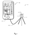
- FIG. 1 1 shows a possible embodiment of a construction measuring device 10 according to the invention.
- the system 10 comprises a control unit 20 with an integrated evaluation and control unit for processing the data and with a touch-sensitive touch display 21 for displaying data / camera images and for marking display points (and inputting Command).
- the control unit 20 (as a user-device interface) and a laser light detector or sensor communicate with each other.
- the control unit 20 and the laser light detector or sensor may be physically separated and interconnected by wireless or wired communications links 22 or provided as a unit.
- wireless or wired communications links 22 for aligning the laser beam 14 to be measured or to be projected points in space at least the laser beam 14 can serve as a measuring beam itself.
- the design survey device 10 may additionally include a direct optical aiming aid, eg a telescope, be equipped.
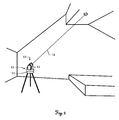
- FIG. 2 illustrates a surveying device 10 according to the invention for measuring and / or marking spatial points of surfaces of a construction, in particular of interior spaces of buildings.
- the construction surveying apparatus 10 comprises a base 11 which stands, for example, on a three-legged tripod with a top 12 rotatably mounted thereon.
- a targeting unit 13 pivotally mounted on the top 12 is provided with a laser source adapted to emit a laser beam 14 and a laser light detector as a rangefinding detector equipped and thus provides a distance measurement functionality.
- the targeting unit 13 further includes an integrated digital camera.
- the target unit 13 with respect to the base 11 is rotatable and pivotable (ie in particular so as to be rotatable about a vertical standing axis and pivotable about a horizontal pivot axis or tilted).
- the construction surveying apparatus 10 also includes an evaluation and control unit, not shown, wherein - also not shown - a first and a second rotary drive, the upper part 12 and the target unit 13 drivable or make in an azimuth and an elevation angle aligned.
- the spatial orientation of the targeting unit 13 relative to the base 11 can be detected by two protractors.
- tilt sensors can be used to determine the placement orientation of the base 11 with respect to the earth's gravity vector be provided.
- the evaluation and control unit is connected to the laser source, the laser light detector and the protractors - and possibly the inclination sensors - to assign a detected distance and detected azimuth and elevation angle of a corresponding orientation of the target unit 13 and thus to determine coordinates for space points.
- the evaluation and control unit is connected to the camera.
- the particular point of interest currently targeted with the target axis 13 can be imaged in the operating state on the display in the image (in a target pixel), in particular indexed using a displayable crosshair.
- the camera image in which the crosshairs can be superimposed on the image in the image corresponding to the target axis, thus serves, in particular, to target the desired target points in space and can be used, for example. be displayed on the display of a hand-held remote control unit for the design survey device (especially as a live video stream).
- the evaluation and control unit as well as the display and the input means can either be arranged directly at the base of the device and / or integrated into a handheld remote control unit.
- the surveying device can thus (either exclusively or in addition to a user interface with display and input means, which can be arranged directly on the base) have a remote control unit with input means and display.
- the surveying device 10 now has a dynamic targeting functionality in which the user can manually give control commands for changing the orientation of the targeting device relative to the base.
- the dynamic targeting functionality can be configured in such a way that it can be activated on the display by marking the target pixel or the crosshair.
- a user can mark a display point 4 on the display.
- a dynamic change in the orientation of the targeting unit 13 is caused by the azimuthal and / or elevative alignment being changed in a motor-driven manner in accordance with the currently determined direction and the currently determined distance from the defined central anchor display point to the currently marked display dot.
- the alignment change speed for changing the alignment of the targeting unit is set dynamically depending on the currently determined distance from the currently marked display point 4 to the crosshair center (which may be defined as a central anchor display point, for example), in particular with increasing distance of the currently marked Display point from the anchor display point respectively the method of the target unit with increasing alignment change speeds takes place.
- the crosshair center which may be defined as a central anchor display point, for example
- the speed of the change of orientation can be at maximum distance of the marked display point 4 from the target pixel 1 or crosshair center (as anchor display point) -. when marking external display points on the display - be maximum, and be selected equal to zero, when the currently selected display point 4 coincides with the target pixel 1 or reticle center as the anchor display point. This means that in the latter case, no change in the orientation of the target unit 13 (that is, no procedure of the target unit) takes place.
- the display is subdivided into a virtual line network 3, corresponding to digitized distances and directions from the target pixel 1 or the crosshair center to groups of display points.
- the virtual line network 3 is formed of concentric circular lines 5 around the crosshair center and radial lines intersecting these circle lines, starting from the crosshair center, so that the display is divided into sectors 7, each containing a group of display points.
- the sectors 7 respectively correspond to concrete values for the orientation change direction and orientation change speed when changing the orientation of the targeting unit 13 (ie, the same display value for the alignment change direction and the orientation change speed is assigned to the display dots located within a sector).
- the change in the orientation of the targeting unit 13, in the vertical and, in particular, simultaneously, horizontal direction, toward the other marked pixel 4 located in one sector in accordance with another spatial dot to be targeted is completed as long as that other pixel is continuously marked.
- the flag is canceled, for example, when the touch of the pixel 4 on a screen designed as a touch screen, the operation of the target unit 13 is stopped.
- a user may at any time mark or touch another display point in another sector 7 to cause a change in the orientation of the targeting unit 13 in accordance with the direction and velocity associated with that sector for changing the orientation.
- Outermost sectors (having a greater distance to the anchor display point) correspond to higher alignment rate velocities, and further inward sectors (which are closer to the anchor display point) correspond to lower alignment rate velocities.
- the orientation change speed associated with the sectors increases.
- the sectors defined by the outermost circle line can also be assigned the highest traversing speed (100%) and a marking of the anchor display point (ie the crosshair center point) can mean a traversing speed of 0%.
- Each sector 7 furthermore corresponds to a specific - ie associated with this - orientation change direction of the targeting unit 13 (azimuthal and elevative).
- the targeting device 13 When marking or touching a pixel eg right of the crosshair center, the targeting device 13 is moved to change the orientation in the horizontal direction to the right until the aforementioned other pixel is no longer marked or touched (for example, because now another other display point is marked - and then the targeting unit is retransmitted at the direction and speed associated with that display point - or no more dot is marked - and then the method of the targeting unit is stopped).
- the targeting unit 13 is moved to change the orientation in the horizontal direction to the right until the aforementioned other pixel is no longer marked or touched (for example, because now another other display point is marked - and then the targeting unit is retransmitted at the direction and speed associated with that display point - or no more dot is marked - and then the method of the targeting unit is stopped).
- 3 illustrated situation corresponds approximately to a change in the orientation of the target unit 13 with an obliquely right above Orientation change direction (ie, an upward pointing direction change component and a rightward direction change component, with the upward component selected slightly larger than the rightward pointing) and at a medium traveling speed.
- the rotary actuators can be controlled in such a way that the targeting unit pivots upward relative to the base at 60% of the maximum deployable pivoting speed and rotates to the right with 40% of the maximum rotary speed that can be provided about the vertical axis.
- the line network 3 is constructed such that it defines a plurality of sectors 7, in particular at least about 30 sectors, in particular at least about 50 sectors.
Landscapes
- Engineering & Computer Science (AREA)
- Physics & Mathematics (AREA)
- General Physics & Mathematics (AREA)
- Radar, Positioning & Navigation (AREA)
- Remote Sensing (AREA)
- Multimedia (AREA)
- Length Measuring Devices By Optical Means (AREA)
- User Interface Of Digital Computer (AREA)
- Aiming, Guidance, Guns With A Light Source, Armor, Camouflage, And Targets (AREA)
- Indication In Cameras, And Counting Of Exposures (AREA)
Claims (15)
- Appareil de mesure (10) pour mesurer des points dans l'espace de surfaces d'une construction - notamment des espaces intérieurs de bâtiments - comportant• une base (11),• une unité de pointage (13) pouvant tourner et pivoter par rapport à la base et fournissant une fonctionnalité de mesure de distance, comportant une source laser conçue pour émettre un faisceau laser (14) dans la direction d'un axe de pointage et un détecteur de lumière laser et comportant une caméra numérique intégrée orientée dans la direction de l'axe de pointage,• une unité d'évaluation et de commande,• un afficheur pour représenter une image de la caméra, et• des moyens d'entrée pour marquer des points d'affichage sur l'afficheur,dans lequel• des premier et deuxième entraînements en rotation permettent d'entraîner et d'orienter l'unité de pointage (13),• une orientation spatiale de l'unité de pointage (13) par rapport à la base (11) peut être détectée par l'intermédiaire de deux dispositifs de mesure angulaire et• l'unité d'évaluation et de commande est reliée à la source laser, au détecteur de lumière laser ainsi qu'aux dispositifs de mesure angulaire pour associer une distance détectée à une orientation correspondante et par conséquent, pour déterminer des coordonnées des points dans l'espace, et est reliée à la caméra,caractérisé en ce que l'appareil de mesure (10) est doté d'une fonctionnalité permettant de modifier manuellement l'orientation de l'unité de pointage (13) d'une manière pouvant être commandée, dans le cadre de laquelle l'orientation de l'unité de pointage (13) est modifiée dynamiquement par le premier ou le deuxième entraînement en rotation en fonction• d'une direction actuelle déterminée en continu et• d'une distance actuelle déterminée en continud'un point d'affichage d'ancrage central défini à un point d'affichage marqué actuel, dans lequel• la direction actuelle respective prédéfinit une direction de modification d'orientation et• la distance actuelle respective prédéfinit une vitesse de modification d'orientationpour la modification de l'orientation de l'unité de pointage (13).
- Appareil de mesure (10) selon la revendication 1,
caractérisé en ce que le point d'affichage qui représente la position de l'axe de pointage dans l'image et par conséquent, un pixel cible (1), est défini en tant que point d'affichage d'ancrage, notamment dans lequel celui-ci est indexé sur l'afficheur par un réticule (2) pouvant être représenté de manière superposée à l'image. - Appareil de mesure (10) selon la revendication 2, caractérisé en ce que la fonctionnalité peut être activée par marquage du point d'affichage ou du réticule (2) représentant le pixel cible (1).
- Appareil de mesure (10) selon l'une quelconque des revendications précédentes, caractérisé en ce que l'afficheur est réalisé sous la forme d'un écran tactile sensible au toucher sur lequel des points d'affichage peuvent être marqués par contact et sur lequel les moyens d'entrée sont par conséquent présents.
- Appareil de mesure (10) selon l'une quelconque des revendications précédentes,
caractérisé en ce que, dans le cadre de la fonctionnalité, la direction de modification d'orientation pour la modification de l'orientation de l'unité de pointage (13) est analogique par rapport à la direction actuelle respective du point d'affichage d'ancrage au point d'affichage marqué actuel, dans lequel la direction de modification d'orientation est par conséquent sélectionnée de manière à ce qu'elle• contienne une composante dirigée vers le haut - et par conséquent, qu'un pivotement de l'unité de pointage soit effectué vers le haut autour d'un axe de pivotement horizontal -, dans le cas où la direction actuelle du point d'affichage d'ancrage au point d'affichage marqué actuel contient une composante pointant vers le haut - et par conséquent, dans le cas où le point d'affichage marqué actuel sur l'afficheur se trouve au-dessus du point d'affichage d'ancrage -,• contienne une composante dirigée vers le bas - et par conséquent, qu'un pivotement de l'unité de pointage soit effectué vers le bas autour de l'axe de pivotement horizontal -, dans le cas où la direction actuelle du point d'affichage d'ancrage au point d'affichage marqué actuel contient une composante pointant vers le bas - et par conséquent, dans le cas où le point d'affichage marqué actuel sur l'afficheur se trouve en-dessous du point d'affichage d'ancrage -,• contienne une composante dirigée vers la gauche - et par conséquent, qu'une rotation de l'unité de pointage soit effectuée vers la gauche autour d'un axe de rotation vertical -, dans le cas où la direction actuelle du point d'affichage d'ancrage au point d'affichage marqué actuel contient une composante pointant vers la gauche - et par conséquent, dans le cas où le point d'affichage marqué actuel sur l'afficheur est situé à gauche du point d'affichage d'ancrage -,• contienne une composante dirigée vers la droite - et par conséquent, qu'une rotation de l'unité de pointage soit effectuée vers la droite autour de l'axe de rotation vertical -, dans le cas où la direction actuelle du point d'affichage d'ancrage au point d'affichage marqué actuel contient une composante pointant vers la droite - et par conséquent, dans le cas où le point d'affichage marqué actuel sur l'afficheur se situe à droite du point d'affichage d'ancrage. - Appareil de mesure (10) selon l'une quelconque des revendications précédentes, caractérisé en ce que, dans le cadre de la fonctionnalité,• la vitesse de modification d'orientation est maximale dans le cas où la distance actuelle du point d'affichage d'ancrage au point d'affichage marqué actuel est également maximale, et• lors d'une coïncidence entre le point d'affichage marqué actuel et le point d'affichage d'ancrage, la vitesse de modification d'orientation est égale à zéro, c'est-à-dire que l'unité de pointage est alors maintenue dans son orientation actuelle.
- Appareil de mesure (10) selon l'une quelconque des revendications précédentes, caractérisé en ce que l'afficheur est subdivisé en des secteurs virtuels (7) au moyen d'un réseau virtuel de lignes (3) appliqué autour du point d'affichage d'ancrage, lequel réseau virtuel de lignes est formé par des circonférences concentriques (5) autour du point d'affichage d'ancrage et par des lignes radiales (6) coupant lesdites circonférences (5) et partant du point d'affichage d'ancrage, dans lequel les secteurs (7) correspondent à des valeurs numérisées pour la direction de modification d'orientation et pour la vitesse de modification d'orientation, et la modification de l'orientation de l'unité de pointage (13) selon la direction de modification d'orientation et la vitesse de modification d'orientation associées au secteur respectif est effectuée tant que l'un des points d'affichage situés à l'intérieur dudit secteur est marqué, et la direction de modification d'orientation et la vitesse de modification d'orientation sont modifiées de manière correspondante dès qu'un point d'affichage se situant à l'intérieur d'un autre secteur est marqué, à savoir dans la direction de modification d'orientation ou à la vitesse de modification d'orientation correspondant à l'autre secteur.
- Appareil de mesure (10) selon la revendication 7, caractérisé en ce que les circonférences concentriques (5) autour du point d'affichage d'ancrage correspondent à des distances différentes du point d'affichage marqué actuel au point d'affichage d'ancrage, de telle sorte que des pas de vitesse de modification d'orientation sont établis, dans lequel les secteurs les plus extérieurs correspondent à la vitesse de modification d'orientation maximale.
- Appareil de mesure (10) selon la revendication 7 ou 8, caractérisé en ce que le réseau virtuel de lignes (3) est réalisé de manière à définir ainsi une pluralité de secteurs (7), notamment au moins environ 30-secteurs (7), en particulier, au moins environ 50 secteurs (7).
- Procédé pour l'orientation commandée manuellement d'une unité de pointage (13) d'un appareil de mesure (10) sur la base d'un marquage de points d'affichage sur un afficheur, dans lequel l'appareil de mesure (10) comporte• une base (11),• l'unité de pointage (13) pouvant tourner et pivoter par rapport à la base et fournissant une fonctionnalité de mesure de distance, comportant une source laser conçue pour émettre un faisceau laser (14) dans la direction d'un axe de pointage et un détecteur de lumière laser et comportant une caméra numérique intégrée orientée dans la direction de l'axe de pointage,• une unité d'évaluation et de commande,• l'afficheur pour représenter une image de la caméra, et• des moyens d'entrée pour marquer les points d'affichage,dans lequel• des premier et deuxième entraînements en rotation permettent d'entraîner et d'orienter l'unité de pointage (13),• une orientation spatiale de l'unité de pointage (13) par rapport à la base (11) peut être détectée par l'intermédiaire de deux dispositifs de mesure angulaire et• l'unité d'évaluation et de commande est reliée à la source laser, au détecteur de lumière laser ainsi qu'aux dispositifs de mesure angulaire pour associer une distance détectée à une orientation correspondante et par conséquent, pour déterminer des coordonnées des points dans l'espace, et est reliée à la caméra,caractérisé en ce que,
de manière continue,• une direction actuelle et• une distance actuelled'un point d'affichage d'ancrage central défini à un point d'affichage marqué actuel sont déterminées et une modification de l'orientation de l'unité de pointage (13) est effectuée dynamiquement en fonction de la direction actuelle respective et de la distance actuelle respective par le premier ou le deuxième entraînement en rotation, dans lequel• la direction actuelle respective prédéfinit une direction de modification d'orientation et• la distance actuelle respective prédéfinit une vitesse de modification d'orientationpour la modification de l'orientation de l'unité de pointage (13). - Procédé selon la revendication 10,
caractérisé en ce que le point d'affichage qui représente la position de l'axe de pointage dans l'image et par conséquent, un pixel cible (1), est défini en tant que point d'affichage d'ancrage, notamment dans lequel celui-ci est indexé sur l'afficheur par un réticule (2) pouvant être représenté de manière superposée à l'image. - Procédé selon l'une quelconque des revendications 10 à 11,
caractérisé en ce que la direction de modification d'orientation pour la modification de l'orientation de l'unité de pointage (13) est sélectionnée de manière analogique par rapport à la direction actuelle respective déterminée du point d'affichage d'ancrage au point d'affichage marqué actuel, dans lequel• la direction de modification d'orientation contient une composante dirigée vers le haut - et par conséquent, un pivotement de l'unité de pointage est effectué vers le haut autour d'un axe de pivotement horizontal -, dans le cas où la direction actuelle du point d'affichage d'ancrage au point d'affichage marqué actuel contient une composante pointant vers le haut - et par conséquent, dans le cas où le point d'affichage marqué actuel sur l'afficheur se trouve au-dessus du point d'affichage d'ancrage -,• la direction de modification d'orientation contient une composante dirigée vers le bas - et par conséquent, un pivotement de l'unité de pointage est effectué vers le bas autour de l'axe de pivotement horizontal -, dans le cas où la direction actuelle du point d'affichage d'ancrage au point d'affichage marqué actuel contient une composante pointant vers le bas - et par conséquent, dans le cas où le point d'affichage marqué actuel sur l'afficheur se trouve en-dessous du point d'affichage d'ancrage -,• la direction de modification d'orientation contient une composante dirigée vers la gauche - et par conséquent, une rotation de l'unité de pointage est effectuée vers la gauche autour d'un axe de rotation vertical -, dans le cas où la direction actuelle du point d'affichage d'ancrage au point d'affichage marqué actuel contient une composante pointant vers la gauche - et par conséquent, dans le cas où le point d'affichage marqué actuel sur l'afficheur est situé à gauche du point d'affichage d'ancrage -, et• la direction de modification d'orientation contient une composante dirigée vers la droite - et par conséquent, une rotation de l'unité de pointage est effectuée vers la droite autour d'un axe de rotation vertical -, dans le cas où la direction actuelle du point d'affichage d'ancrage au point d'affichage marqué actuel contient une composante pointant vers la droite - et par conséquent, dans le cas où le point d'affichage marqué actuel sur l'afficheur se situe à droite du point d'affichage d'ancrage. - Procédé selon l'une quelconque des revendications 10 à 12, caractérisé en ce que• la vitesse de modification d'orientation est maximale dans le cas où la distance actuelle du point d'affichage marqué actuel au point d'affichage d'ancrage est maximale, et• lors d'une coïncidence entre le point d'affichage marqué actuel et le point d'affichage d'ancrage, la vitesse de modification d'orientation est égale à zéro, c'est-à-dire que l'unité de pointage est alors maintenue dans son orientation actuelle.
- Procédé selon l'une quelconque des revendications 10 à 13,
caractérisé en ce que l'afficheur est subdivisé en des secteurs virtuels (7) au moyen d'un réseau virtuel de lignes (3) appliqué autour du point d'affichage d'ancrage, lequel réseau virtuel de lignes est formé par des circonférences concentriques (5) autour du point d'affichage d'ancrage et par des lignes radiales (6) coupant lesdites circonférences (5) et partant du point d'affichage d'ancrage, dans lequel les secteurs (7) correspondent à des valeurs numérisées pour la direction de modification d'orientation et pour la vitesse de modification d'orientation, et la modification de l'orientation de l'unité de pointage (13) selon la direction de modification d'orientation et la vitesse de modification d'orientation associées au secteur respectif est effectuée tant que l'un des points d'affichage situés à l'intérieur dudit secteur est marqué, et la direction de modification d'orientation et la vitesse de modification d'orientation sont modifiées de manière correspondante dès qu'un point d'affichage se situant à l'intérieur d'un autre secteur est marqué, à savoir dans la direction de modification d'orientation ou à la vitesse de modification d'orientation correspondant à l'autre secteur. - Produit de programme d'ordinateur comportant un code de programme qui est stocké sur un support lisible par machine, pour mettre en oeuvre le procédé d'orientation commandée manuellement d'une unité de pointage (13) d'un appareil de mesure (10) sur la base d'un marquage de points d'affichage sur un afficheur selon l'une quelconque des revendications 10 à 14, notamment lorsque le programme est exécuté sur une unité de traitement de données électronique réalisée sous la forme de l'unité d'évaluation et de commande de l'appareil de mesure (10) selon l'une quelconque des revendications 1 à 9.
Priority Applications (1)
| Application Number | Priority Date | Filing Date | Title |
|---|---|---|---|
| EP12701084.1A EP2663836B1 (fr) | 2011-01-11 | 2012-01-10 | Appareil de mesure ayant une fonctionnalité de ciblage dynamique et procédé associé |
Applications Claiming Priority (3)
| Application Number | Priority Date | Filing Date | Title |
|---|---|---|---|
| EP11150580A EP2474810A1 (fr) | 2011-01-11 | 2011-01-11 | Appareil de mesure doté d'une fonctionnalité de pointage dynamique |
| EP12701084.1A EP2663836B1 (fr) | 2011-01-11 | 2012-01-10 | Appareil de mesure ayant une fonctionnalité de ciblage dynamique et procédé associé |
| PCT/EP2012/050300 WO2012095415A1 (fr) | 2011-01-11 | 2012-01-10 | Appareil de mesure ayant une fonctionnalité de ciblage dynamique et procédé associé |
Publications (2)
| Publication Number | Publication Date |
|---|---|
| EP2663836A1 EP2663836A1 (fr) | 2013-11-20 |
| EP2663836B1 true EP2663836B1 (fr) | 2016-11-23 |
Family
ID=44065449
Family Applications (2)
| Application Number | Title | Priority Date | Filing Date |
|---|---|---|---|
| EP11150580A Withdrawn EP2474810A1 (fr) | 2011-01-11 | 2011-01-11 | Appareil de mesure doté d'une fonctionnalité de pointage dynamique |
| EP12701084.1A Not-in-force EP2663836B1 (fr) | 2011-01-11 | 2012-01-10 | Appareil de mesure ayant une fonctionnalité de ciblage dynamique et procédé associé |
Family Applications Before (1)
| Application Number | Title | Priority Date | Filing Date |
|---|---|---|---|
| EP11150580A Withdrawn EP2474810A1 (fr) | 2011-01-11 | 2011-01-11 | Appareil de mesure doté d'une fonctionnalité de pointage dynamique |
Country Status (8)
| Country | Link |
|---|---|
| US (1) | US9829314B2 (fr) |
| EP (2) | EP2474810A1 (fr) |
| KR (1) | KR101580871B1 (fr) |
| CN (1) | CN103328925B (fr) |
| AU (1) | AU2012206597B9 (fr) |
| BR (1) | BR112013017111A2 (fr) |
| CA (1) | CA2822180C (fr) |
| WO (1) | WO2012095415A1 (fr) |
Families Citing this family (9)
| Publication number | Priority date | Publication date | Assignee | Title |
|---|---|---|---|---|
| EP2551636A1 (fr) * | 2011-07-25 | 2013-01-30 | Leica Geosystems AG | Dispositif de mesure pouvant être commandé sans contact et son procédé de commande |
| EP2557392A1 (fr) * | 2011-08-11 | 2013-02-13 | Leica Geosystems AG | Dispositif de mesure et procédé doté d'une fonctionnalité de ciblage échelonnable et basée sur l'orientation d'une unité de télécommande |
| EP2998698B1 (fr) * | 2014-09-17 | 2017-02-01 | Leica Geosystems AG | Dispositif d'arpentage doté d'une fonction d'étalonnage des positions d'optique de focalisation réglables en fonction de la distance |
| CN104481125A (zh) * | 2014-12-11 | 2015-04-01 | 苏州金螳螂建筑装饰股份有限公司 | 一种光定位仪 |
| DE102015214148A1 (de) * | 2015-07-08 | 2017-01-12 | Robert Bosch Gmbh | System mit einem Laser-Messmodul |
| WO2017028203A1 (fr) * | 2015-08-18 | 2017-02-23 | 北京艾肯拓科技有限公司 | Procédé et dispositif pour générer des coordonnées géographiques |
| DE102016211742A1 (de) * | 2016-06-29 | 2018-01-04 | Robert Bosch Gmbh | Verfahren zum Betrieb eines Laserentfernungsmessgeräts |
| CN111970425A (zh) * | 2018-07-02 | 2020-11-20 | 深圳市深联创展科技开发有限公司 | 激光清障器的成像瞄准方法 |
| JP7587817B2 (ja) * | 2020-11-27 | 2024-11-21 | 株式会社イシダ | 物品処理装置及び下流側装置 |
Family Cites Families (17)
| Publication number | Priority date | Publication date | Assignee | Title |
|---|---|---|---|---|
| DE4032657A1 (de) * | 1990-10-15 | 1992-04-16 | Pietzsch Ibp Gmbh | Verfahren und messeinrichtung zur positionsbestimmung von raumpunkten |
| DE4443413C2 (de) | 1994-12-07 | 1996-09-19 | Schiele Josef | Verfahren und Vorrichtung zum Vermessen und Markieren |
| DE19648626A1 (de) | 1996-11-12 | 1998-05-14 | Flexicon Gmbh | Verfahren und Vorrichtung zur Flächen- und Raumvermessung |
| US7856750B2 (en) * | 1997-12-08 | 2010-12-28 | Horus Vision Llc | Apparatus and method for calculating aiming point information |
| US7342650B2 (en) * | 2002-10-12 | 2008-03-11 | Leica Geosystems Ag | Electronic display and control device for a measuring device |
| EP1460377A3 (fr) * | 2003-03-21 | 2004-09-29 | Leica Geosystems AG | Procédé et dispositif pour traitement d'image dans un appareil de mesure géodésique |
| KR100608892B1 (ko) * | 2004-01-06 | 2006-08-03 | 한국표준과학연구원 | 변위와 각도 변화를 동시에 측정하기 위한 방법과 장치 |
| FR2876446B1 (fr) | 2004-02-19 | 2007-04-20 | Measurix Sarl | Dispositif et procede de mesure de la superficie de surfaces planes polygonales dans l'espace. |
| US7933001B2 (en) * | 2005-07-11 | 2011-04-26 | Kabushiki Kaisha Topcon | Geographic data collecting system |
| DE602005012824D1 (de) * | 2005-08-22 | 2009-04-02 | Unisantis Fze | Vorrichtung und Verfahren zum Positionieren einer Röntgenlinse und Röntgengerät mit einer solchen Vorrichtung |
| US7301698B2 (en) * | 2005-11-23 | 2007-11-27 | Pacific Telescope Corp. | Method for automatically aligning telescope |
| US8229166B2 (en) * | 2009-07-07 | 2012-07-24 | Trimble Navigation, Ltd | Image-based tracking |
| DE112007003284T5 (de) * | 2007-01-26 | 2009-12-24 | Trimble Jena Gmbh | Optisches Instrument und Verfahren zum Erhalten von Abstands- und Bildinformation |
| US8031332B2 (en) * | 2008-11-20 | 2011-10-04 | Trimble Navigation Limited | Layout method |
| US8615376B2 (en) * | 2010-05-21 | 2013-12-24 | Sure-Shot Medical Device Inc. | Method and apparatus for dimensional measurement |
| EP2423640A1 (fr) | 2010-08-23 | 2012-02-29 | Hexagon Technology Center GmbH | Capteur d'inclinaison pour un appareil et procédé de détermination de l'inclinaison d'un appareil |
| EP2458328B1 (fr) * | 2010-11-24 | 2016-01-27 | Leica Geosystems AG | Dispositif de mesure et de construction doté d'une fonctionnalité de recherche de point d'aplomb automatique |
-
2011
- 2011-01-11 EP EP11150580A patent/EP2474810A1/fr not_active Withdrawn
-
2012
- 2012-01-10 EP EP12701084.1A patent/EP2663836B1/fr not_active Not-in-force
- 2012-01-10 WO PCT/EP2012/050300 patent/WO2012095415A1/fr not_active Ceased
- 2012-01-10 AU AU2012206597A patent/AU2012206597B9/en not_active Ceased
- 2012-01-10 CN CN201280005068.8A patent/CN103328925B/zh not_active Expired - Fee Related
- 2012-01-10 KR KR1020137021145A patent/KR101580871B1/ko not_active Expired - Fee Related
- 2012-01-10 CA CA2822180A patent/CA2822180C/fr not_active Expired - Fee Related
- 2012-01-10 BR BR112013017111-1A patent/BR112013017111A2/pt not_active Application Discontinuation
- 2012-01-10 US US13/993,014 patent/US9829314B2/en not_active Expired - Fee Related
Non-Patent Citations (1)
| Title |
|---|
| None * |
Also Published As
| Publication number | Publication date |
|---|---|
| WO2012095415A1 (fr) | 2012-07-19 |
| US20130278752A1 (en) | 2013-10-24 |
| BR112013017111A2 (pt) | 2020-10-27 |
| CA2822180C (fr) | 2016-11-15 |
| US9829314B2 (en) | 2017-11-28 |
| AU2012206597B2 (en) | 2014-07-31 |
| CN103328925A (zh) | 2013-09-25 |
| AU2012206597A1 (en) | 2013-06-20 |
| KR101580871B1 (ko) | 2015-12-29 |
| EP2474810A1 (fr) | 2012-07-11 |
| CA2822180A1 (fr) | 2012-07-19 |
| KR20130102123A (ko) | 2013-09-16 |
| EP2663836A1 (fr) | 2013-11-20 |
| CN103328925B (zh) | 2016-02-10 |
| AU2012206597B9 (en) | 2014-08-07 |
Similar Documents
| Publication | Publication Date | Title |
|---|---|---|
| EP2663836B1 (fr) | Appareil de mesure ayant une fonctionnalité de ciblage dynamique et procédé associé | |
| EP2742323B1 (fr) | Dispositif de mesure et procédé doté d'une fonctionnalité de ciblage échelonnable et basée sur l'orientation d'une unité de télécommande | |
| EP2663835B1 (fr) | Appareil de mesure à fonctionnalité de changement de représentation automatique | |
| EP2638358B1 (fr) | Dispositif pour mesurer et marquer des points le long de courbes de niveau horizontales | |
| EP2726816B1 (fr) | Dispositif de mesure de construction destiné à suivre, mesurer et marquer des surfaces contiguës au niveau des bords et des points de coin | |
| EP2458328B1 (fr) | Dispositif de mesure et de construction doté d'une fonctionnalité de recherche de point d'aplomb automatique | |
| EP2810019B2 (fr) | Système de mesure doté d'un appareil de mesure et d'un module de balayage | |
| EP1606581B1 (fr) | Procede et dispositif de traitement d'image d'un appareil de mesure geodesique | |
| EP2765388B1 (fr) | Contrôleur de terrain mobile destiné à arpentage et commande à distance | |
| EP2616770B1 (fr) | Système de mesure géodésique comportant un appareil de prise de vues intégré à une unité de télécommande | |
| DE102011077080B4 (de) | System für zweidimensionale Grundriss- und Punktübertragung | |
| EP3894785A1 (fr) | Dispositif de mesure, système de mesure et instruments d'aide à la mesure | |
| WO2006097408A1 (fr) | Procede et systeme pour determiner la position et l'orientation d'un objet | |
| WO2014027002A1 (fr) | Appareil de mesure de distance à main pourvu d'une unité de détermination d'angle | |
| EP2697606A1 (fr) | Système de marquage géodésique pour le marquage de points de mire | |
| WO2013037971A1 (fr) | Appareil de mesure et procédé destiné à la représentation filtrée d'informations d'objet |
Legal Events
| Date | Code | Title | Description |
|---|---|---|---|
| PUAI | Public reference made under article 153(3) epc to a published international application that has entered the european phase |
Free format text: ORIGINAL CODE: 0009012 |
|
| 17P | Request for examination filed |
Effective date: 20130524 |
|
| AK | Designated contracting states |
Kind code of ref document: A1 Designated state(s): AL AT BE BG CH CY CZ DE DK EE ES FI FR GB GR HR HU IE IS IT LI LT LU LV MC MK MT NL NO PL PT RO RS SE SI SK SM TR |
|
| DAX | Request for extension of the european patent (deleted) | ||
| REG | Reference to a national code |
Ref country code: DE Ref legal event code: R079 Ref document number: 502012008848 Country of ref document: DE Free format text: PREVIOUS MAIN CLASS: G01C0015000000 Ipc: G01C0011000000 |
|
| GRAP | Despatch of communication of intention to grant a patent |
Free format text: ORIGINAL CODE: EPIDOSNIGR1 |
|
| RIC1 | Information provided on ipc code assigned before grant |
Ipc: G01C 11/00 20060101AFI20160714BHEP Ipc: G01C 15/00 20060101ALI20160714BHEP |
|
| INTG | Intention to grant announced |
Effective date: 20160809 |
|
| GRAS | Grant fee paid |
Free format text: ORIGINAL CODE: EPIDOSNIGR3 |
|
| GRAA | (expected) grant |
Free format text: ORIGINAL CODE: 0009210 |
|
| AK | Designated contracting states |
Kind code of ref document: B1 Designated state(s): AL AT BE BG CH CY CZ DE DK EE ES FI FR GB GR HR HU IE IS IT LI LT LU LV MC MK MT NL NO PL PT RO RS SE SI SK SM TR |
|
| REG | Reference to a national code |
Ref country code: GB Ref legal event code: FG4D Free format text: NOT ENGLISH |
|
| REG | Reference to a national code |
Ref country code: CH Ref legal event code: NV Representative=s name: KAMINSKI HARMANN PATENTANWAELTE AG, LI Ref country code: CH Ref legal event code: EP |
|
| REG | Reference to a national code |
Ref country code: IE Ref legal event code: FG4D Free format text: LANGUAGE OF EP DOCUMENT: GERMAN |
|
| REG | Reference to a national code |
Ref country code: AT Ref legal event code: REF Ref document number: 848322 Country of ref document: AT Kind code of ref document: T Effective date: 20161215 |
|
| REG | Reference to a national code |
Ref country code: DE Ref legal event code: R096 Ref document number: 502012008848 Country of ref document: DE |
|
| REG | Reference to a national code |
Ref country code: FR Ref legal event code: PLFP Year of fee payment: 6 |
|
| PG25 | Lapsed in a contracting state [announced via postgrant information from national office to epo] |
Ref country code: LV Free format text: LAPSE BECAUSE OF FAILURE TO SUBMIT A TRANSLATION OF THE DESCRIPTION OR TO PAY THE FEE WITHIN THE PRESCRIBED TIME-LIMIT Effective date: 20161123 |
|
| REG | Reference to a national code |
Ref country code: NL Ref legal event code: FP |
|
| REG | Reference to a national code |
Ref country code: LT Ref legal event code: MG4D |
|
| PG25 | Lapsed in a contracting state [announced via postgrant information from national office to epo] |
Ref country code: GR Free format text: LAPSE BECAUSE OF FAILURE TO SUBMIT A TRANSLATION OF THE DESCRIPTION OR TO PAY THE FEE WITHIN THE PRESCRIBED TIME-LIMIT Effective date: 20170224 Ref country code: NO Free format text: LAPSE BECAUSE OF FAILURE TO SUBMIT A TRANSLATION OF THE DESCRIPTION OR TO PAY THE FEE WITHIN THE PRESCRIBED TIME-LIMIT Effective date: 20170223 Ref country code: LT Free format text: LAPSE BECAUSE OF FAILURE TO SUBMIT A TRANSLATION OF THE DESCRIPTION OR TO PAY THE FEE WITHIN THE PRESCRIBED TIME-LIMIT Effective date: 20161123 Ref country code: SE Free format text: LAPSE BECAUSE OF FAILURE TO SUBMIT A TRANSLATION OF THE DESCRIPTION OR TO PAY THE FEE WITHIN THE PRESCRIBED TIME-LIMIT Effective date: 20161123 |
|
| PG25 | Lapsed in a contracting state [announced via postgrant information from national office to epo] |
Ref country code: BE Free format text: LAPSE BECAUSE OF NON-PAYMENT OF DUE FEES Effective date: 20170131 Ref country code: PL Free format text: LAPSE BECAUSE OF FAILURE TO SUBMIT A TRANSLATION OF THE DESCRIPTION OR TO PAY THE FEE WITHIN THE PRESCRIBED TIME-LIMIT Effective date: 20161123 Ref country code: HR Free format text: LAPSE BECAUSE OF FAILURE TO SUBMIT A TRANSLATION OF THE DESCRIPTION OR TO PAY THE FEE WITHIN THE PRESCRIBED TIME-LIMIT Effective date: 20161123 Ref country code: ES Free format text: LAPSE BECAUSE OF FAILURE TO SUBMIT A TRANSLATION OF THE DESCRIPTION OR TO PAY THE FEE WITHIN THE PRESCRIBED TIME-LIMIT Effective date: 20161123 Ref country code: FI Free format text: LAPSE BECAUSE OF FAILURE TO SUBMIT A TRANSLATION OF THE DESCRIPTION OR TO PAY THE FEE WITHIN THE PRESCRIBED TIME-LIMIT Effective date: 20161123 Ref country code: RS Free format text: LAPSE BECAUSE OF FAILURE TO SUBMIT A TRANSLATION OF THE DESCRIPTION OR TO PAY THE FEE WITHIN THE PRESCRIBED TIME-LIMIT Effective date: 20161123 Ref country code: PT Free format text: LAPSE BECAUSE OF FAILURE TO SUBMIT A TRANSLATION OF THE DESCRIPTION OR TO PAY THE FEE WITHIN THE PRESCRIBED TIME-LIMIT Effective date: 20170323 |
|
| PG25 | Lapsed in a contracting state [announced via postgrant information from national office to epo] |
Ref country code: SK Free format text: LAPSE BECAUSE OF FAILURE TO SUBMIT A TRANSLATION OF THE DESCRIPTION OR TO PAY THE FEE WITHIN THE PRESCRIBED TIME-LIMIT Effective date: 20161123 Ref country code: EE Free format text: LAPSE BECAUSE OF FAILURE TO SUBMIT A TRANSLATION OF THE DESCRIPTION OR TO PAY THE FEE WITHIN THE PRESCRIBED TIME-LIMIT Effective date: 20161123 Ref country code: RO Free format text: LAPSE BECAUSE OF FAILURE TO SUBMIT A TRANSLATION OF THE DESCRIPTION OR TO PAY THE FEE WITHIN THE PRESCRIBED TIME-LIMIT Effective date: 20161123 Ref country code: CZ Free format text: LAPSE BECAUSE OF FAILURE TO SUBMIT A TRANSLATION OF THE DESCRIPTION OR TO PAY THE FEE WITHIN THE PRESCRIBED TIME-LIMIT Effective date: 20161123 Ref country code: DK Free format text: LAPSE BECAUSE OF FAILURE TO SUBMIT A TRANSLATION OF THE DESCRIPTION OR TO PAY THE FEE WITHIN THE PRESCRIBED TIME-LIMIT Effective date: 20161123 |
|
| REG | Reference to a national code |
Ref country code: DE Ref legal event code: R097 Ref document number: 502012008848 Country of ref document: DE |
|
| PG25 | Lapsed in a contracting state [announced via postgrant information from national office to epo] |
Ref country code: SM Free format text: LAPSE BECAUSE OF FAILURE TO SUBMIT A TRANSLATION OF THE DESCRIPTION OR TO PAY THE FEE WITHIN THE PRESCRIBED TIME-LIMIT Effective date: 20161123 Ref country code: BG Free format text: LAPSE BECAUSE OF FAILURE TO SUBMIT A TRANSLATION OF THE DESCRIPTION OR TO PAY THE FEE WITHIN THE PRESCRIBED TIME-LIMIT Effective date: 20170223 |
|
| PG25 | Lapsed in a contracting state [announced via postgrant information from national office to epo] |
Ref country code: MC Free format text: LAPSE BECAUSE OF FAILURE TO SUBMIT A TRANSLATION OF THE DESCRIPTION OR TO PAY THE FEE WITHIN THE PRESCRIBED TIME-LIMIT Effective date: 20161123 |
|
| PLBE | No opposition filed within time limit |
Free format text: ORIGINAL CODE: 0009261 |
|
| STAA | Information on the status of an ep patent application or granted ep patent |
Free format text: STATUS: NO OPPOSITION FILED WITHIN TIME LIMIT |
|
| 26N | No opposition filed |
Effective date: 20170824 |
|
| REG | Reference to a national code |
Ref country code: IE Ref legal event code: MM4A |
|
| PG25 | Lapsed in a contracting state [announced via postgrant information from national office to epo] |
Ref country code: LU Free format text: LAPSE BECAUSE OF NON-PAYMENT OF DUE FEES Effective date: 20170110 Ref country code: SI Free format text: LAPSE BECAUSE OF FAILURE TO SUBMIT A TRANSLATION OF THE DESCRIPTION OR TO PAY THE FEE WITHIN THE PRESCRIBED TIME-LIMIT Effective date: 20161123 |
|
| REG | Reference to a national code |
Ref country code: FR Ref legal event code: PLFP Year of fee payment: 7 |
|
| REG | Reference to a national code |
Ref country code: BE Ref legal event code: MM Effective date: 20170131 |
|
| PG25 | Lapsed in a contracting state [announced via postgrant information from national office to epo] |
Ref country code: IE Free format text: LAPSE BECAUSE OF NON-PAYMENT OF DUE FEES Effective date: 20170110 |
|
| REG | Reference to a national code |
Ref country code: AT Ref legal event code: MM01 Ref document number: 848322 Country of ref document: AT Kind code of ref document: T Effective date: 20170110 |
|
| PG25 | Lapsed in a contracting state [announced via postgrant information from national office to epo] |
Ref country code: AT Free format text: LAPSE BECAUSE OF NON-PAYMENT OF DUE FEES Effective date: 20170110 |
|
| PG25 | Lapsed in a contracting state [announced via postgrant information from national office to epo] |
Ref country code: MT Free format text: LAPSE BECAUSE OF FAILURE TO SUBMIT A TRANSLATION OF THE DESCRIPTION OR TO PAY THE FEE WITHIN THE PRESCRIBED TIME-LIMIT Effective date: 20161123 |
|
| PG25 | Lapsed in a contracting state [announced via postgrant information from national office to epo] |
Ref country code: HU Free format text: LAPSE BECAUSE OF FAILURE TO SUBMIT A TRANSLATION OF THE DESCRIPTION OR TO PAY THE FEE WITHIN THE PRESCRIBED TIME-LIMIT; INVALID AB INITIO Effective date: 20120110 |
|
| PG25 | Lapsed in a contracting state [announced via postgrant information from national office to epo] |
Ref country code: CY Free format text: LAPSE BECAUSE OF NON-PAYMENT OF DUE FEES Effective date: 20161123 |
|
| PG25 | Lapsed in a contracting state [announced via postgrant information from national office to epo] |
Ref country code: MK Free format text: LAPSE BECAUSE OF FAILURE TO SUBMIT A TRANSLATION OF THE DESCRIPTION OR TO PAY THE FEE WITHIN THE PRESCRIBED TIME-LIMIT Effective date: 20161123 |
|
| PG25 | Lapsed in a contracting state [announced via postgrant information from national office to epo] |
Ref country code: TR Free format text: LAPSE BECAUSE OF FAILURE TO SUBMIT A TRANSLATION OF THE DESCRIPTION OR TO PAY THE FEE WITHIN THE PRESCRIBED TIME-LIMIT Effective date: 20161123 |
|
| PGFP | Annual fee paid to national office [announced via postgrant information from national office to epo] |
Ref country code: DE Payment date: 20200121 Year of fee payment: 9 Ref country code: NL Payment date: 20200121 Year of fee payment: 9 Ref country code: IT Payment date: 20200131 Year of fee payment: 9 Ref country code: GB Payment date: 20200124 Year of fee payment: 9 |
|
| PGFP | Annual fee paid to national office [announced via postgrant information from national office to epo] |
Ref country code: CH Payment date: 20200121 Year of fee payment: 9 |
|
| PGFP | Annual fee paid to national office [announced via postgrant information from national office to epo] |
Ref country code: FR Payment date: 20200121 Year of fee payment: 9 |
|
| PG25 | Lapsed in a contracting state [announced via postgrant information from national office to epo] |
Ref country code: IS Free format text: LAPSE BECAUSE OF FAILURE TO SUBMIT A TRANSLATION OF THE DESCRIPTION OR TO PAY THE FEE WITHIN THE PRESCRIBED TIME-LIMIT Effective date: 20170323 Ref country code: AL Free format text: LAPSE BECAUSE OF FAILURE TO SUBMIT A TRANSLATION OF THE DESCRIPTION OR TO PAY THE FEE WITHIN THE PRESCRIBED TIME-LIMIT Effective date: 20161123 |
|
| REG | Reference to a national code |
Ref country code: DE Ref legal event code: R119 Ref document number: 502012008848 Country of ref document: DE |
|
| REG | Reference to a national code |
Ref country code: CH Ref legal event code: PL |
|
| REG | Reference to a national code |
Ref country code: NL Ref legal event code: MM Effective date: 20210201 |
|
| GBPC | Gb: european patent ceased through non-payment of renewal fee |
Effective date: 20210110 |
|
| PG25 | Lapsed in a contracting state [announced via postgrant information from national office to epo] |
Ref country code: NL Free format text: LAPSE BECAUSE OF NON-PAYMENT OF DUE FEES Effective date: 20210201 Ref country code: FR Free format text: LAPSE BECAUSE OF NON-PAYMENT OF DUE FEES Effective date: 20210131 |
|
| PG25 | Lapsed in a contracting state [announced via postgrant information from national office to epo] |
Ref country code: GB Free format text: LAPSE BECAUSE OF NON-PAYMENT OF DUE FEES Effective date: 20210110 Ref country code: DE Free format text: LAPSE BECAUSE OF NON-PAYMENT OF DUE FEES Effective date: 20210803 Ref country code: CH Free format text: LAPSE BECAUSE OF NON-PAYMENT OF DUE FEES Effective date: 20210131 Ref country code: LI Free format text: LAPSE BECAUSE OF NON-PAYMENT OF DUE FEES Effective date: 20210131 |
|
| PG25 | Lapsed in a contracting state [announced via postgrant information from national office to epo] |
Ref country code: IT Free format text: LAPSE BECAUSE OF NON-PAYMENT OF DUE FEES Effective date: 20210110 |