EP2664029B1 - Hornstrahler auf basis einer bestückten leiterplatte - Google Patents
Hornstrahler auf basis einer bestückten leiterplatte Download PDFInfo
- Publication number
- EP2664029B1 EP2664029B1 EP12734164.2A EP12734164A EP2664029B1 EP 2664029 B1 EP2664029 B1 EP 2664029B1 EP 12734164 A EP12734164 A EP 12734164A EP 2664029 B1 EP2664029 B1 EP 2664029B1
- Authority
- EP
- European Patent Office
- Prior art keywords
- feed horn
- layer
- printed circuit
- horn
- circuit board
- Prior art date
- Legal status (The legal status is an assumption and is not a legal conclusion. Google has not performed a legal analysis and makes no representation as to the accuracy of the status listed.)
- Active
Links
Images




Classifications
-
- H—ELECTRICITY
- H01—ELECTRIC ELEMENTS
- H01Q—ANTENNAS, i.e. RADIO AERIALS
- H01Q15/00—Devices for reflection, refraction, diffraction or polarisation of waves radiated from an antenna, e.g. quasi-optical devices
- H01Q15/0006—Devices acting selectively as reflecting surface, as diffracting or as refracting device, e.g. frequency filtering or angular spatial filtering devices
- H01Q15/0086—Devices acting selectively as reflecting surface, as diffracting or as refracting device, e.g. frequency filtering or angular spatial filtering devices said selective devices having materials with a synthesized negative refractive index, e.g. metamaterials or left-handed materials
-
- H—ELECTRICITY
- H01—ELECTRIC ELEMENTS
- H01Q—ANTENNAS, i.e. RADIO AERIALS
- H01Q1/00—Details of, or arrangements associated with, antennas
- H01Q1/36—Structural form of radiating elements, e.g. cone, spiral, umbrella; Particular materials used therewith
- H01Q1/38—Structural form of radiating elements, e.g. cone, spiral, umbrella; Particular materials used therewith formed by a conductive layer on an insulating support
-
- H—ELECTRICITY
- H01—ELECTRIC ELEMENTS
- H01Q—ANTENNAS, i.e. RADIO AERIALS
- H01Q13/00—Waveguide horns or mouths; Slot antennas; Leaky-waveguide antennas; Equivalent structures causing radiation along the transmission path of a guided wave
- H01Q13/02—Waveguide horns
Definitions
- the subject technology relates in general to feed horns, and more particularly to high performance, low mass, affordable printed circuit board based feed horns.
- High performance antenna systems such as those of the space communications industry (e.g., for ground terminal antennas or onboard a spacecraft) may require antenna feeds that are wide in bandwidth, exhibit low sidelobes, and exhibit low cross polarization.
- custom designed corrugated feed horns that are machined from solid blocks of metal may be utilized in such systems (e.g., to achieve required bandwidth and radio frequency performance). While corrugated feed horns solve the performance demands of these systems, the horns may be expensive and heavy.
- US 2009/0284429 A1 discloses a horn antenna including a conducting horn having an inner wall and a first dielectric layer lining the inner wall of the conductive horn.
- the first dielectric layer includes a metamaterial having a relative dielectric constant of greater than zero and less than one.
- the horn antenna may further include a dielectric core abutting at least a portion of the first dielectric layer.
- the dielectric layer includes a fluid.
- a waveguide including a metamaterial is also disclosed.
- aspects of the subject technology provide a new class of feed horns based on the use of metamaterial printed wiring board (PWB) or printed circuit board (PCB) liners on the walls of the feed horns.
- PWB metamaterial printed wiring board
- PCB printed circuit board
- These feed horns may be implemented to achieve low cost operation.
- PCBs making up the metamaterial liner may be assembled together in such a manner as to form a feed horn with a square or rectangular aperture shape, although other suitable shapes are possible.
- These PCBs may be fabricated from standard low cost, off-the-shelf dielectric material.
- a conductor artwork pattern on the PCB surface forming the interior surface of the feed horn can be designed such that the PCB feed horn yields radio frequency (RF) properties similar to that of a corrugated feed horn.
- RF radio frequency
- a simple flat plate ground plane bonded to the back side of the PCB can serve as the feed horn structure.
- a new class of feed horns based on the use of metamaterial printed circuit board (PCB) liners on the inner surface of the feed horns is provided.
- PCB printed circuit board
- the layer of printed circuit board lines substantially the entire inner surface of the outer layer.
- the layer of printed circuit board is flexible, rigid or semi rigid.
- the layer of printed circuit board comprises at least one of a dielectric and a metal.
- the layer of printed circuit board has metal traces printed thereon.
- the dielectric is further comprised of at least one of a ceramic, a glass or a polymer-based material.
- the feed horn is used to transmit and/or receive electromagnetic waves.
- the layer of printed circuit board is either a single layer of printed circuit board, a multi layer of printed circuit boards or a printed circuit board with multi layers.
- the feed horn may further comprise a dielectric layer with an effective index of refraction above 1.
- a cross section of the outer layer is either circular, elliptical, square, rectangular, hexagonal, octagonal or any shape with n-fold symmetry, wherein n is an integer.
- the feed horn is either directly radiating or serving as a feed to a reflector. Further, the feed horn's operating frequency range is from UHF (Ultra High Frequency) to THz (terahertz).
- the feed horn may be used for space, airborne or terrestrial applications.
- the layer of printed circuit board covers either all of the inner surface of the outer layer, or part of the inner surface of the outer layer. Further, the layer of printed circuit board has an effective index of refraction between 0 and 1 in all or part of an operating frequency range. Still further, the layer of printed circuit board is a low loss tangent material and not an absorber.
- the feed horn's outer layer may comprise four walls so that a cross section of the outer layer is rectangular. Further, the layer of printed circuit board only lines the inner surface of two of the four walls that are opposite to each other, and the layer of printed circuit board does not line the inner surface of the other two walls.
- a feed horn comprises one or more horn walls. At least one of the one or more horn walls comprises a layer of printed circuit board, wherein the layer of printed circuit board is a metamaterial for manipulating propagation of electromagnetic waves. In one embodiment, all the feed horn walls are made up entirely of printed circuit boards. In another embodiment, the one or more horn walls are all electrically connected together.
- a new class of power combiner assembly based on the use of metamaterial printed circuit board (PCB) liners on the inner surface of a feed horn.
- a power combiner assembly comprises a plurality of power amplifiers and a feed horn comprising an outer layer having an inner surface.
- the feed horn further comprises a layer of printed circuit board lining substantially the entire inner surface of the outer layer, wherein the layer of printed circuit board is a metamaterial for manipulating propagation of electromagnetic waves.
- the plurality of power amplifiers are configured to provide power to the feed horn and the feed horn is configured to combine the power from the plurality of power amplifiers into a single power transmission.
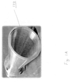
- FIG. 1A and 1B illustrate an example of a prior art feed horn.
- the example shown is a custom designed corrugated feed horn 100 that is machined from a solid block of metal.
- FIG. 1A provides a front view of the custom designed corrugated feed horn 100
- FIG. 1B provides a side view of the custom designed corrugated feed horn 100 that has been cross sectioned for inspection.
- This type of custom designed corrugated feed horn is typically used in high performance antenna systems such as those of the space communications industry (e.g., for ground terminal antennas or onboard a spacecraft), which demand antenna feeds that are wide in bandwidth, exhibit low sidelobes, and exhibit low cross polarization.
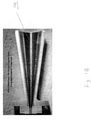
- FIG. 2A and 2B illustrate a first example of a PCB based feed horn 200, which achieves reduction in both cost and weight over prior art feed horn.
- FIG. 2A provides a front view of a PCB based feed horn 200
- FIG. 2B gives the side view of a PCB based feed horn 200.
- FIG. 2A and FIG. 2B show that PCB based feed horn 200 is comprised of an outer layer 210 and an inner PCB layer 220.
- feed horn 200 may be characterized as comprising of an outer layer 210 having an inner surface and a layer 220 of PCB lining substantially the entire inner surface of the outer layer 210.
- the outer layer 210 may be a metal ground plate that is conductive electrically.
- another embodiment may have a layer of PCB lining only a portion of the inner surface of the outer layer 210.
- a layer of PCB may only line the inner surface of two of the four walls that are opposite to each other. In that example, no PCB layer will be lining the inner surface of the other two remaining walls.
- the feed horn embodiment shown in FIG. 2 has a square-shaped aperture or cross section, so the feed horn has four walls.
- FIG. 3 illustrates how PCB based parts may be formed by lining the inner surface of an outer layer with a layer of PCB (printed circuit board).
- a PCB based feed horn is to be fabricated from PCB based parts 310, 320, 330, and 340.
- the feed horn embodiment shown in FIG. 3 will have a square-shaped aperture or cross section, there will be four walls to the feed horn, corresponding to the four PCB based parts 310, 320, 330, and 340.
- PCB based part 310 is blown up to show the details of outer layer 312 and PCB layer 314.
- FIG. 3 shows the outer layer 312 as a simple flat plate that is bonded to the back side of the PCB layer 314.
- Outer layer 312 serves as the feed horn structure support in this example.
- the feed horn shown is made up of a ground plane and a layer of PCB.
- This feed horn may use materials and fabrication techniques common in the PCB industry. Because the PCB and ground plane may be fabricated using common PCB processes, the cost of the horn as compared to that of a similar horn of corrugated construction is drastically reduced.
- the PCB conductive pattern may be designed using standard PCB design tools. In addition, the pattern for the entire horn may be photo etched in a single process step.
- the flat ground plane 312 may be optimally designed, meeting structural requirements with the lowest cost / mass solution.
- the flat plate ground plane 312 and PCB layer 314 may weigh much less than a machined corrugated horn.
- PCB based part 310 is further enlarged to show how an artwork pattern of metal traces printed on PCB based parts may form an interior 'metamaterial' feed horn surface.
- FIG. 4 shows PCB layer 314 sitting on top of conducting outer layer 312, which is a simple flat metal plate ground plane in this example.
- a unit metal trace figure 410 is repeated in a regular pattern over the surface of PCB layer 314.
- these unit metal trace figures are all connected to a copper backside plate of the PCB through individual metal vias for each unit metal trace figure.
- dielectric material Surrounding the metal vias is dielectric material.
- other artwork pattern of metal trace printed on PCB based parts may also form an interior 'metamaterial' feed horn surface.
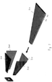
- FIG. 5 illustrates how PCB based parts may be assembled together to form a first example of a PCB based feed horn.
- PCB based parts 310, 320, 330, and 340 are assembled together to form PCB based feed horn 200.
- the low cost PCBs and ground planes can be laminated by PCB suppliers.
- the PCB walls i.e., PCB based parts 310, 320, 330, and 340
- the welded or bolted together PCB walls are able provide adequate structural support for the feed horn, it may be possible to construct the feed horn without the use of the metal plate ground plane from the outer layer 312.
- the copper backside plate of the PCB will serve as the ground plane.
- horns with square apertures may yield very similar performance as horns with circular apertures (i.e., conical horns).
- the conductor artwork pattern on the PCB surface forming the interior surface of the feed horn (as shown in FIG. 4 ) can be designed such that the PCB feed horn yields RF properties similar to that of a corrugated feed horn, with the potential for even larger bandwidth for multi-band operations (Ku and Ka-band).
- metamaterial horns may have intrinsically larger bandwidth than corrugated horns, thereby enabling applications with over an octave bandwidth.
- the example feed horn shown in FIG. 5 has an aperture that is square.
- horn aperture may be circular, elliptical, square, rectangular, hexagonal or octagonal.
- the horn aperture may be any shape with n-fold symmetry, where n is an integer.
- a feed horn with both a square or a rectangular aperture, having four horn walls may be utilized.
- a layer of PCB may only line the inner surface of two of the four walls that are opposite to each other.
- horn walls 320 and 340 may be lined with a layer of PCB, while horn walls 310 and 330 remain free of PCB.
- horn walls 310 and 330 may be lined with a layer of PCB, while horn walls 320 and 340 remain free of PCB.
- the subject technology may be used in various markets, including for example and without limitation, advanced sensors, data transmission and communications, and radar and active phased arrays markets.
- a phrase such as "an aspect” does not imply that such aspect is essential to the subject technology or that such aspect applies to all configurations of the subject technology.
- a disclosure relating to an aspect may apply to all configurations, or one or more configurations.
- An aspect may provide one or more examples of the disclosure.
- a phrase such as an "aspect” may refer to one or more aspects and vice versa.
- a phrase such as an "embodiment” does not imply that such embodiment is essential to the subject technology or that such embodiment applies to all configurations of the subject technology.
- a disclosure relating to an embodiment may apply to all embodiments, or one or more embodiments.
- An embodiment may provide one or more examples of the disclosure.
- a phrase such an "embodiment” may refer to one or more embodiments and vice versa.
Landscapes
- Waveguide Aerials (AREA)
Claims (16)
- Hornstrahler (200), umfassend:Hornwände (310, 320, 330, 340), die aus einer Außenlage (210, 312) gebildet sind, die eine Innenfläche aufweist; dadurch gekennzeichnet, dasseine Leiterplattenlage (220, 314) im Wesentlichen die gesamte Innenfläche der Außenlage (210, 312) auskleidet und Hornwände (310, 320, 330, 340) bildet, wobei ein Vorlagenmuster von Metallleiterbahnen, das auf die Leiterplattenlage (220, 314) gedruckt ist, eine innere Hornstrahlerfläche aus Metamaterial zum Beeinflussen der Ausbreitung elektromagnetischer Wellen bildet und wobei die von den Leiterplatten gebildeten Hornwände (310, 320, 330, 340) miteinander verschweißt oder verschraubt sind.
- Hornstrahler (200) nach Anspruch 1, wobei die Leiterplattenlage (220, 314) biegsam, starr oder halbstarr ist.
- Hornstrahler (200) nach Anspruch 2, wobei die Leiterplattenlage (220, 314) mindestens eines von einem Dielektrikum und einem Metall umfasst.
- Hornstrahler (200) nach Anspruch 3, wobei das Dielektrikum mindestens eines von einer Keramik, einem Glas oder einem polymerbasierten Material umfasst.
- Hornstrahler (200) nach Anspruch 1, wobei der Hornstrahler (200) zum Senden und/oder Empfangen von elektromagnetischen Wellen verwendet wird.
- Hornstrahler (200) nach Anspruch 1, wobei die Leiterplattenlage (220, 314) entweder eine Leiterplatteneinfachlage oder eine Leiterplattenmehrfachlage oder eine Leiterplatte mit mehreren Lagen ist.
- Hornstrahler (200) nach Anspruch 1, ferner umfassend eine Dielektrikumlage mit einem effektiven Brechungsindex über 1.
- Hornstrahler (200) nach Anspruch 1, wobei ein Querschnitt der Außenlage (210, 312) entweder kreisförmig, elliptisch, quadratisch, rechteckig, sechseckig oder achteckig ist oder eine beliebige Form mit n-zähliger Symmetrie aufweist, wobei n eine Ganzzahl ist.
- Hornstrahler (200) nach Anspruch 1, wobei der Hornstrahler (200) entweder direktstrahlend ist oder als Einspeisung für einen Reflektor dient.
- Hornstrahler (200) nach Anspruch 1, wobei ein Betriebsfrequenzbereich des Hornstrahlers (200) von UHF (Ultra High Frequenz) bis THz (Terahertz) reicht.
- Hornstrahler (200) nach Anspruch 1, wobei die Leiterplattenlage (220, 314) in einem gesamten Betriebsfrequenzbereich oder in einem Teil von diesem einen effektiven Brechungsindex zwischen 0 und 1 aufweist.
- Hornstrahler (200) nach Anspruch 1, wobei die Leiterplattenlage (220, 314) ein Material mit niedrigem Verlusttangens und kein Absorber ist.
- Hornstrahler (200) nach Anspruch 1, wobei die Außenlage (210, 312) vier Wände umfasst, sodass ein Querschnitt der Außenlage (210, 312) rechteckig ist, wobei die Leiterplattenlage (220, 314) die Innenfläche von zwei einander gegenüberliegenden Wänden der vier Wände auskleidet.
- Hornstrahler (200) nach Anspruch 1, wobei die Hornwände (310, 320, 330, 340) des Hornstrahlers (200) alle miteinander elektrisch verbunden sind.
- Hornstrahler nach Anspruch 1, wobei die Außenlage (312) leitend ist und eine Einheitsmetallleiterbahnenfigur (410) mit einem regelmäßigen Muster über der Leiterplattenlage (220, 314) wiederholt wird, wobei die Einheitsmetallleiterbahnenfiguren (410) alle mit der leitenden Außenlage (312) durch einzelne Metalldurchkontaktierungen für jede Einheitsmetallleiterbahnenfigur (410) verbunden sind.
- Leistungskombiniereranordnung, umfassend:eine Vielzahl von Leistungsverstärkern; undeinen Hornstrahler (200) nach einem der Ansprüche 1 bis 15;wobei die Vielzahl von Leistungsverstärkern dazu eingerichtet sind, dem Hornstrahler (200) Leistung zuzuführen, und wobei der Hornstrahler (200) dazu eingerichtet ist, die Leistung von der Vielzahl von Leistungsverstärkern in einer einzigen Leistungsübertragung zu vereinigen.
Applications Claiming Priority (2)
| Application Number | Priority Date | Filing Date | Title |
|---|---|---|---|
| US201161432136P | 2011-01-12 | 2011-01-12 | |
| PCT/US2012/021104 WO2012097169A1 (en) | 2011-01-12 | 2012-01-12 | Printed circuit board based feed horn |
Publications (3)
| Publication Number | Publication Date |
|---|---|
| EP2664029A1 EP2664029A1 (de) | 2013-11-20 |
| EP2664029A4 EP2664029A4 (de) | 2014-12-31 |
| EP2664029B1 true EP2664029B1 (de) | 2022-03-09 |
Family
ID=46454862
Family Applications (1)
| Application Number | Title | Priority Date | Filing Date |
|---|---|---|---|
| EP12734164.2A Active EP2664029B1 (de) | 2011-01-12 | 2012-01-12 | Hornstrahler auf basis einer bestückten leiterplatte |
Country Status (3)
| Country | Link |
|---|---|
| US (1) | US9300054B2 (de) |
| EP (1) | EP2664029B1 (de) |
| WO (1) | WO2012097169A1 (de) |
Families Citing this family (8)
| Publication number | Priority date | Publication date | Assignee | Title |
|---|---|---|---|---|
| CN103682648B (zh) * | 2012-08-31 | 2018-02-23 | 深圳光启创新技术有限公司 | 一种喇叭天线 |
| ES2546784B1 (es) * | 2014-03-28 | 2016-07-04 | Adartia Servicios, S.L. | Dispositivo amplificador para antenas de radar |
| US9698492B2 (en) * | 2015-01-28 | 2017-07-04 | Northrop Grumman Systems Corporation | Low-cost diplexed multiple beam integrated antenna system for LEO satellite constellation |
| CN105337043A (zh) * | 2015-10-13 | 2016-02-17 | 中国电子科技集团公司第五十四研究所 | 一种薄壁异形铜喇叭天线及其加工方法 |
| CN111168287B (zh) * | 2019-12-09 | 2021-09-14 | 常州工业职业技术学院 | 一种智能机器人数字化焊接系统及其工作方法 |
| CN111900550B (zh) * | 2020-08-31 | 2021-05-28 | 西安电子科技大学 | 一种融合阻抗与相位双重调制的双源超表面高定向性天线 |
| KR102864054B1 (ko) * | 2020-10-23 | 2025-09-24 | 삼성전자주식회사 | 인터포저를 포함하는 안테나 구조 및 이를 포함하는 전자 장치. |
| CN116062571A (zh) * | 2021-10-29 | 2023-05-05 | 霍尼韦尔国际公司 | 用于电梯定位的平截头体设计的雷达反射器 |
Family Cites Families (14)
| Publication number | Priority date | Publication date | Assignee | Title |
|---|---|---|---|---|
| JP2584168B2 (ja) * | 1992-04-28 | 1997-02-19 | ユピテル工業株式会社 | マイクロ波検出器 |
| JP3739637B2 (ja) * | 2000-07-27 | 2006-01-25 | アルプス電気株式会社 | 一次放射器 |
| JP4491189B2 (ja) | 2002-07-15 | 2010-06-30 | 大学共同利用機関法人自然科学研究機構 | コルゲートホーンの製造方法及びコルゲートホーン |
| US6950073B2 (en) * | 2002-08-20 | 2005-09-27 | Aerosat Corporation | Communication system with broadband antenna |
| US7816247B2 (en) * | 2003-02-25 | 2010-10-19 | Broadcom Corporation | Optimization of routing layers and board space requirements for ball grid array package implementations including array corner considerations |
| US6879298B1 (en) * | 2003-10-15 | 2005-04-12 | Harris Corporation | Multi-band horn antenna using corrugations having frequency selective surfaces |
| US7161550B2 (en) * | 2004-04-20 | 2007-01-09 | Tdk Corporation | Dual- and quad-ridged horn antenna with improved antenna pattern characteristics |
| DE102006019688B4 (de) * | 2006-04-27 | 2014-10-23 | Vega Grieshaber Kg | Patchantenne mit Keramikscheibe als Abdeckung |
| CN103441339B (zh) * | 2006-04-27 | 2016-01-13 | 泰科电子服务有限责任公司 | 异向材料天线设备 |
| US7629937B2 (en) * | 2008-02-25 | 2009-12-08 | Lockheed Martin Corporation | Horn antenna, waveguide or apparatus including low index dielectric material |
| US8072386B2 (en) * | 2008-02-25 | 2011-12-06 | Lockheed Martin Corporation | Horn antenna, waveguide or apparatus including low index dielectric material |
| US8164531B2 (en) * | 2008-05-20 | 2012-04-24 | Lockheed Martin Corporation | Antenna array with metamaterial lens |
| US8466370B2 (en) * | 2008-09-30 | 2013-06-18 | Lockheed Martin Corporation | Low index metamaterial |
| CN102422486B (zh) * | 2009-03-11 | 2014-04-09 | 泰科电子服务股份有限公司 | 高增益超材料天线设备 |
-
2012
- 2012-01-12 EP EP12734164.2A patent/EP2664029B1/de active Active
- 2012-01-12 US US13/349,504 patent/US9300054B2/en active Active
- 2012-01-12 WO PCT/US2012/021104 patent/WO2012097169A1/en not_active Ceased
Also Published As
| Publication number | Publication date |
|---|---|
| EP2664029A1 (de) | 2013-11-20 |
| EP2664029A4 (de) | 2014-12-31 |
| US9300054B2 (en) | 2016-03-29 |
| WO2012097169A1 (en) | 2012-07-19 |
| US20120176287A1 (en) | 2012-07-12 |
Similar Documents
| Publication | Publication Date | Title |
|---|---|---|
| EP2664029B1 (de) | Hornstrahler auf basis einer bestückten leiterplatte | |
| US10931020B2 (en) | Waveguide feed network architecture for wideband, low profile, dual polarized planar horn array antennas | |
| EP2551959B1 (de) | Breitbandantennenelement mit Verbindungsring für phasengesteuerte Arrays | |
| US9112262B2 (en) | Planar array feed for satellite communications | |
| CN104078768B (zh) | 宽带宽角圆极化堆叠微带天线 | |
| US10283876B1 (en) | Dual-polarized, planar slot-aperture antenna element | |
| US8773323B1 (en) | Multi-band antenna element with integral faraday cage for phased arrays | |
| US20180017664A1 (en) | Frequency selective surface, wireless communication device, and radar device | |
| US20150130673A1 (en) | Beam-Steered Wide Bandwidth Electromagnetic Band Gap Antenna | |
| CN105990681B (zh) | 一种天线及机载通信设备 | |
| US20120306698A1 (en) | Planar array feed for satellite communications | |
| US10897090B2 (en) | Electronics and filter-integrated, dual-polarized transition and radiator for phased array sensors | |
| KR20110023768A (ko) | 트리플레이트 선로 층간 접속기 및 평면 어레이 안테나 | |
| EP3410533B1 (de) | Breitbandantennensystem | |
| TW201902023A (zh) | 具夾持機構之天線孔徑 | |
| US9929470B2 (en) | Low profile wideband planar antenna element with integrated baluns | |
| US12525724B2 (en) | Ultra-wideband circular-polarized radiation element with integrated feeding | |
| CN112242612B (zh) | 贴片天线 | |
| US20170317421A1 (en) | Low Profile Wideband Planar Antenna Element | |
| Shelley et al. | X-and Ka-band low profile antennas for aeronautical and land mobile satcom | |
| CN111987446B (zh) | 应用在毫米波频段的双极化短背射天线 | |
| EP4064456B1 (de) | Antennenanordnung | |
| US10680340B2 (en) | Cone-based multi-layer wide band antenna | |
| US11038273B1 (en) | Electronically scanning antenna assembly | |
| CN105990647B (zh) | 通信天线、天线系统和通信设备 |
Legal Events
| Date | Code | Title | Description |
|---|---|---|---|
| PUAI | Public reference made under article 153(3) epc to a published international application that has entered the european phase |
Free format text: ORIGINAL CODE: 0009012 |
|
| 17P | Request for examination filed |
Effective date: 20130724 |
|
| AK | Designated contracting states |
Kind code of ref document: A1 Designated state(s): AL AT BE BG CH CY CZ DE DK EE ES FI FR GB GR HR HU IE IS IT LI LT LU LV MC MK MT NL NO PL PT RO RS SE SI SK SM TR |
|
| DAX | Request for extension of the european patent (deleted) | ||
| A4 | Supplementary search report drawn up and despatched |
Effective date: 20141202 |
|
| RIC1 | Information provided on ipc code assigned before grant |
Ipc: H01Q 13/02 20060101ALI20141126BHEP Ipc: H01Q 15/00 20060101ALI20141126BHEP Ipc: H01Q 1/38 20060101ALI20141126BHEP Ipc: H01Q 13/00 20060101AFI20141126BHEP |
|
| STAA | Information on the status of an ep patent application or granted ep patent |
Free format text: STATUS: EXAMINATION IS IN PROGRESS |
|
| 17Q | First examination report despatched |
Effective date: 20171026 |
|
| GRAP | Despatch of communication of intention to grant a patent |
Free format text: ORIGINAL CODE: EPIDOSNIGR1 |
|
| STAA | Information on the status of an ep patent application or granted ep patent |
Free format text: STATUS: GRANT OF PATENT IS INTENDED |
|
| INTG | Intention to grant announced |
Effective date: 20210824 |
|
| GRAS | Grant fee paid |
Free format text: ORIGINAL CODE: EPIDOSNIGR3 |
|
| GRAA | (expected) grant |
Free format text: ORIGINAL CODE: 0009210 |
|
| STAA | Information on the status of an ep patent application or granted ep patent |
Free format text: STATUS: THE PATENT HAS BEEN GRANTED |
|
| AK | Designated contracting states |
Kind code of ref document: B1 Designated state(s): AL AT BE BG CH CY CZ DE DK EE ES FI FR GB GR HR HU IE IS IT LI LT LU LV MC MK MT NL NO PL PT RO RS SE SI SK SM TR |
|
| REG | Reference to a national code |
Ref country code: GB Ref legal event code: FG4D |
|
| REG | Reference to a national code |
Ref country code: CH Ref legal event code: EP Ref country code: AT Ref legal event code: REF Ref document number: 1474914 Country of ref document: AT Kind code of ref document: T Effective date: 20220315 |
|
| REG | Reference to a national code |
Ref country code: DE Ref legal event code: R096 Ref document number: 602012077807 Country of ref document: DE |
|
| REG | Reference to a national code |
Ref country code: IE Ref legal event code: FG4D |
|
| REG | Reference to a national code |
Ref country code: LT Ref legal event code: MG9D |
|
| REG | Reference to a national code |
Ref country code: NL Ref legal event code: MP Effective date: 20220309 |
|
| PG25 | Lapsed in a contracting state [announced via postgrant information from national office to epo] |
Ref country code: SE Free format text: LAPSE BECAUSE OF FAILURE TO SUBMIT A TRANSLATION OF THE DESCRIPTION OR TO PAY THE FEE WITHIN THE PRESCRIBED TIME-LIMIT Effective date: 20220309 Ref country code: RS Free format text: LAPSE BECAUSE OF FAILURE TO SUBMIT A TRANSLATION OF THE DESCRIPTION OR TO PAY THE FEE WITHIN THE PRESCRIBED TIME-LIMIT Effective date: 20220309 Ref country code: NO Free format text: LAPSE BECAUSE OF FAILURE TO SUBMIT A TRANSLATION OF THE DESCRIPTION OR TO PAY THE FEE WITHIN THE PRESCRIBED TIME-LIMIT Effective date: 20220609 Ref country code: LT Free format text: LAPSE BECAUSE OF FAILURE TO SUBMIT A TRANSLATION OF THE DESCRIPTION OR TO PAY THE FEE WITHIN THE PRESCRIBED TIME-LIMIT Effective date: 20220309 Ref country code: HR Free format text: LAPSE BECAUSE OF FAILURE TO SUBMIT A TRANSLATION OF THE DESCRIPTION OR TO PAY THE FEE WITHIN THE PRESCRIBED TIME-LIMIT Effective date: 20220309 Ref country code: BG Free format text: LAPSE BECAUSE OF FAILURE TO SUBMIT A TRANSLATION OF THE DESCRIPTION OR TO PAY THE FEE WITHIN THE PRESCRIBED TIME-LIMIT Effective date: 20220609 |
|
| REG | Reference to a national code |
Ref country code: AT Ref legal event code: MK05 Ref document number: 1474914 Country of ref document: AT Kind code of ref document: T Effective date: 20220309 |
|
| PG25 | Lapsed in a contracting state [announced via postgrant information from national office to epo] |
Ref country code: LV Free format text: LAPSE BECAUSE OF FAILURE TO SUBMIT A TRANSLATION OF THE DESCRIPTION OR TO PAY THE FEE WITHIN THE PRESCRIBED TIME-LIMIT Effective date: 20220309 Ref country code: GR Free format text: LAPSE BECAUSE OF FAILURE TO SUBMIT A TRANSLATION OF THE DESCRIPTION OR TO PAY THE FEE WITHIN THE PRESCRIBED TIME-LIMIT Effective date: 20220610 Ref country code: FI Free format text: LAPSE BECAUSE OF FAILURE TO SUBMIT A TRANSLATION OF THE DESCRIPTION OR TO PAY THE FEE WITHIN THE PRESCRIBED TIME-LIMIT Effective date: 20220309 |
|
| PG25 | Lapsed in a contracting state [announced via postgrant information from national office to epo] |
Ref country code: NL Free format text: LAPSE BECAUSE OF FAILURE TO SUBMIT A TRANSLATION OF THE DESCRIPTION OR TO PAY THE FEE WITHIN THE PRESCRIBED TIME-LIMIT Effective date: 20220309 |
|
| PG25 | Lapsed in a contracting state [announced via postgrant information from national office to epo] |
Ref country code: SM Free format text: LAPSE BECAUSE OF FAILURE TO SUBMIT A TRANSLATION OF THE DESCRIPTION OR TO PAY THE FEE WITHIN THE PRESCRIBED TIME-LIMIT Effective date: 20220309 Ref country code: SK Free format text: LAPSE BECAUSE OF FAILURE TO SUBMIT A TRANSLATION OF THE DESCRIPTION OR TO PAY THE FEE WITHIN THE PRESCRIBED TIME-LIMIT Effective date: 20220309 Ref country code: RO Free format text: LAPSE BECAUSE OF FAILURE TO SUBMIT A TRANSLATION OF THE DESCRIPTION OR TO PAY THE FEE WITHIN THE PRESCRIBED TIME-LIMIT Effective date: 20220309 Ref country code: PT Free format text: LAPSE BECAUSE OF FAILURE TO SUBMIT A TRANSLATION OF THE DESCRIPTION OR TO PAY THE FEE WITHIN THE PRESCRIBED TIME-LIMIT Effective date: 20220711 Ref country code: ES Free format text: LAPSE BECAUSE OF FAILURE TO SUBMIT A TRANSLATION OF THE DESCRIPTION OR TO PAY THE FEE WITHIN THE PRESCRIBED TIME-LIMIT Effective date: 20220309 Ref country code: EE Free format text: LAPSE BECAUSE OF FAILURE TO SUBMIT A TRANSLATION OF THE DESCRIPTION OR TO PAY THE FEE WITHIN THE PRESCRIBED TIME-LIMIT Effective date: 20220309 Ref country code: CZ Free format text: LAPSE BECAUSE OF FAILURE TO SUBMIT A TRANSLATION OF THE DESCRIPTION OR TO PAY THE FEE WITHIN THE PRESCRIBED TIME-LIMIT Effective date: 20220309 Ref country code: AT Free format text: LAPSE BECAUSE OF FAILURE TO SUBMIT A TRANSLATION OF THE DESCRIPTION OR TO PAY THE FEE WITHIN THE PRESCRIBED TIME-LIMIT Effective date: 20220309 |
|
| PG25 | Lapsed in a contracting state [announced via postgrant information from national office to epo] |
Ref country code: PL Free format text: LAPSE BECAUSE OF FAILURE TO SUBMIT A TRANSLATION OF THE DESCRIPTION OR TO PAY THE FEE WITHIN THE PRESCRIBED TIME-LIMIT Effective date: 20220309 Ref country code: IS Free format text: LAPSE BECAUSE OF FAILURE TO SUBMIT A TRANSLATION OF THE DESCRIPTION OR TO PAY THE FEE WITHIN THE PRESCRIBED TIME-LIMIT Effective date: 20220709 Ref country code: AL Free format text: LAPSE BECAUSE OF FAILURE TO SUBMIT A TRANSLATION OF THE DESCRIPTION OR TO PAY THE FEE WITHIN THE PRESCRIBED TIME-LIMIT Effective date: 20220309 |
|
| REG | Reference to a national code |
Ref country code: DE Ref legal event code: R097 Ref document number: 602012077807 Country of ref document: DE |
|
| PLBE | No opposition filed within time limit |
Free format text: ORIGINAL CODE: 0009261 |
|
| STAA | Information on the status of an ep patent application or granted ep patent |
Free format text: STATUS: NO OPPOSITION FILED WITHIN TIME LIMIT |
|
| PG25 | Lapsed in a contracting state [announced via postgrant information from national office to epo] |
Ref country code: DK Free format text: LAPSE BECAUSE OF FAILURE TO SUBMIT A TRANSLATION OF THE DESCRIPTION OR TO PAY THE FEE WITHIN THE PRESCRIBED TIME-LIMIT Effective date: 20220309 |
|
| 26N | No opposition filed |
Effective date: 20221212 |
|
| PG25 | Lapsed in a contracting state [announced via postgrant information from national office to epo] |
Ref country code: SI Free format text: LAPSE BECAUSE OF FAILURE TO SUBMIT A TRANSLATION OF THE DESCRIPTION OR TO PAY THE FEE WITHIN THE PRESCRIBED TIME-LIMIT Effective date: 20220309 |
|
| PG25 | Lapsed in a contracting state [announced via postgrant information from national office to epo] |
Ref country code: IT Free format text: LAPSE BECAUSE OF FAILURE TO SUBMIT A TRANSLATION OF THE DESCRIPTION OR TO PAY THE FEE WITHIN THE PRESCRIBED TIME-LIMIT Effective date: 20220309 |
|
| REG | Reference to a national code |
Ref country code: CH Ref legal event code: PL |
|
| PG25 | Lapsed in a contracting state [announced via postgrant information from national office to epo] |
Ref country code: LU Free format text: LAPSE BECAUSE OF NON-PAYMENT OF DUE FEES Effective date: 20230112 |
|
| REG | Reference to a national code |
Ref country code: BE Ref legal event code: MM Effective date: 20230131 |
|
| PG25 | Lapsed in a contracting state [announced via postgrant information from national office to epo] |
Ref country code: LI Free format text: LAPSE BECAUSE OF NON-PAYMENT OF DUE FEES Effective date: 20230131 Ref country code: CH Free format text: LAPSE BECAUSE OF NON-PAYMENT OF DUE FEES Effective date: 20230131 |
|
| PG25 | Lapsed in a contracting state [announced via postgrant information from national office to epo] |
Ref country code: BE Free format text: LAPSE BECAUSE OF NON-PAYMENT OF DUE FEES Effective date: 20230131 |
|
| PG25 | Lapsed in a contracting state [announced via postgrant information from national office to epo] |
Ref country code: IE Free format text: LAPSE BECAUSE OF NON-PAYMENT OF DUE FEES Effective date: 20230112 |
|
| PG25 | Lapsed in a contracting state [announced via postgrant information from national office to epo] |
Ref country code: MC Free format text: LAPSE BECAUSE OF FAILURE TO SUBMIT A TRANSLATION OF THE DESCRIPTION OR TO PAY THE FEE WITHIN THE PRESCRIBED TIME-LIMIT Effective date: 20220309 |
|
| PG25 | Lapsed in a contracting state [announced via postgrant information from national office to epo] |
Ref country code: MC Free format text: LAPSE BECAUSE OF FAILURE TO SUBMIT A TRANSLATION OF THE DESCRIPTION OR TO PAY THE FEE WITHIN THE PRESCRIBED TIME-LIMIT Effective date: 20220309 |
|
| PGFP | Annual fee paid to national office [announced via postgrant information from national office to epo] |
Ref country code: DE Payment date: 20250129 Year of fee payment: 14 |
|
| PGFP | Annual fee paid to national office [announced via postgrant information from national office to epo] |
Ref country code: FR Payment date: 20250127 Year of fee payment: 14 |
|
| PGFP | Annual fee paid to national office [announced via postgrant information from national office to epo] |
Ref country code: GB Payment date: 20250127 Year of fee payment: 14 |
|
| PG25 | Lapsed in a contracting state [announced via postgrant information from national office to epo] |
Ref country code: CY Free format text: LAPSE BECAUSE OF FAILURE TO SUBMIT A TRANSLATION OF THE DESCRIPTION OR TO PAY THE FEE WITHIN THE PRESCRIBED TIME-LIMIT; INVALID AB INITIO Effective date: 20120112 |
|
| PG25 | Lapsed in a contracting state [announced via postgrant information from national office to epo] |
Ref country code: HU Free format text: LAPSE BECAUSE OF FAILURE TO SUBMIT A TRANSLATION OF THE DESCRIPTION OR TO PAY THE FEE WITHIN THE PRESCRIBED TIME-LIMIT; INVALID AB INITIO Effective date: 20120112 |
|
| PG25 | Lapsed in a contracting state [announced via postgrant information from national office to epo] |
Ref country code: TR Free format text: LAPSE BECAUSE OF FAILURE TO SUBMIT A TRANSLATION OF THE DESCRIPTION OR TO PAY THE FEE WITHIN THE PRESCRIBED TIME-LIMIT Effective date: 20220309 |