EP2664065B1 - Unité de commande pour un appareil de véhicule - Google Patents
Unité de commande pour un appareil de véhicule Download PDFInfo
- Publication number
- EP2664065B1 EP2664065B1 EP12700806.8A EP12700806A EP2664065B1 EP 2664065 B1 EP2664065 B1 EP 2664065B1 EP 12700806 A EP12700806 A EP 12700806A EP 2664065 B1 EP2664065 B1 EP 2664065B1
- Authority
- EP
- European Patent Office
- Prior art keywords
- sensor
- plate
- operating unit
- sensor plate
- electrode
- Prior art date
- Legal status (The legal status is an assumption and is not a legal conclusion. Google has not performed a legal analysis and makes no representation as to the accuracy of the status listed.)
- Active
Links
Images


Classifications
-
- H—ELECTRICITY
- H03—ELECTRONIC CIRCUITRY
- H03K—PULSE TECHNIQUE
- H03K17/00—Electronic switching or gating, i.e. not by contact-making and –breaking
- H03K17/94—Electronic switching or gating, i.e. not by contact-making and –breaking characterised by the way in which the control signals are generated
- H03K17/96—Touch switches
- H03K17/962—Capacitive touch switches
- H03K17/9622—Capacitive touch switches using a plurality of detectors, e.g. keyboard
-
- B—PERFORMING OPERATIONS; TRANSPORTING
- B60—VEHICLES IN GENERAL
- B60K—ARRANGEMENT OR MOUNTING OF PROPULSION UNITS OR OF TRANSMISSIONS IN VEHICLES; ARRANGEMENT OR MOUNTING OF PLURAL DIVERSE PRIME-MOVERS IN VEHICLES; AUXILIARY DRIVES FOR VEHICLES; INSTRUMENTATION OR DASHBOARDS FOR VEHICLES; ARRANGEMENTS IN CONNECTION WITH COOLING, AIR INTAKE, GAS EXHAUST OR FUEL SUPPLY OF PROPULSION UNITS IN VEHICLES
- B60K35/00—Instruments specially adapted for vehicles; Arrangement of instruments in or on vehicles
- B60K35/10—Input arrangements, i.e. from user to vehicle, associated with vehicle functions or specially adapted therefor
-
- B—PERFORMING OPERATIONS; TRANSPORTING
- B60—VEHICLES IN GENERAL
- B60K—ARRANGEMENT OR MOUNTING OF PROPULSION UNITS OR OF TRANSMISSIONS IN VEHICLES; ARRANGEMENT OR MOUNTING OF PLURAL DIVERSE PRIME-MOVERS IN VEHICLES; AUXILIARY DRIVES FOR VEHICLES; INSTRUMENTATION OR DASHBOARDS FOR VEHICLES; ARRANGEMENTS IN CONNECTION WITH COOLING, AIR INTAKE, GAS EXHAUST OR FUEL SUPPLY OF PROPULSION UNITS IN VEHICLES
- B60K35/00—Instruments specially adapted for vehicles; Arrangement of instruments in or on vehicles
- B60K35/80—Arrangements for controlling instruments
- B60K35/81—Arrangements for controlling instruments for controlling displays
-
- H—ELECTRICITY
- H03—ELECTRONIC CIRCUITRY
- H03K—PULSE TECHNIQUE
- H03K17/00—Electronic switching or gating, i.e. not by contact-making and –breaking
- H03K17/94—Electronic switching or gating, i.e. not by contact-making and –breaking characterised by the way in which the control signals are generated
- H03K17/965—Switches controlled by moving an element forming part of the switch
- H03K17/975—Switches controlled by moving an element forming part of the switch using a capacitive movable element
-
- B—PERFORMING OPERATIONS; TRANSPORTING
- B60—VEHICLES IN GENERAL
- B60K—ARRANGEMENT OR MOUNTING OF PROPULSION UNITS OR OF TRANSMISSIONS IN VEHICLES; ARRANGEMENT OR MOUNTING OF PLURAL DIVERSE PRIME-MOVERS IN VEHICLES; AUXILIARY DRIVES FOR VEHICLES; INSTRUMENTATION OR DASHBOARDS FOR VEHICLES; ARRANGEMENTS IN CONNECTION WITH COOLING, AIR INTAKE, GAS EXHAUST OR FUEL SUPPLY OF PROPULSION UNITS IN VEHICLES
- B60K2360/00—Indexing scheme associated with groups B60K35/00 or B60K37/00 relating to details of instruments or dashboards
- B60K2360/141—Activation of instrument input devices by approaching fingers or pens
Definitions
- the invention relates to an operating unit for a vehicle component, which may be, in particular, a radio, a CD and / or DVD player, a navigation device, an infotainment device, a heating or climate control device or a human-machine interface ,
- a vehicle component which may be, in particular, a radio, a CD and / or DVD player, a navigation device, an infotainment device, a heating or climate control device or a human-machine interface ,
- control units which are normally arranged in the vehicle interior and are provided with a vehicle interior facing front wall.
- symbol fields are arranged, which are located on pushbuttons, rotary knobs, toggle or rocker buttons or even on fixed surfaces.
- Control units for vehicle components that have capacitive proximity sensors usually have a housing that is closed to the operator side by a front wall or generally a cover (for example, front panel). At a certain distance behind the front panel is usually a carrier plate in the form of a printed circuit board, which in addition to tracks also has a variety of electrical, electronic and mechanical components.
- a carrier plate in the form of a printed circuit board, which in addition to tracks also has a variety of electrical, electronic and mechanical components.
- the capacitive sensor electrode of the proximity sensor is usually held by a sensor carrier body, which may have a wide variety of configurations. Examples of operating units of the aforementioned type can be found in WO-A-2008/015225 . EP-A-1 739 839 . DE-A-10 2007 025 564 . DE-A-10 2005 029 512 . DE-A-10 2005 029 503 and DE-A-10 2005 025 021 ,
- a capacitive proximity and / or touch sensor which has an electrically conductive plastic body as a sensor.
- the plastic body is attached to the edge of a carrier board and protrudes from this.
- the carrier board runs essentially at right angles to a contact surface (for example a cover element), on the underside of which the plastic body rests.
- the object of the invention is to improve an operating unit for a vehicle component with a capacitive proximity sensor to the effect that the sensor electrode carrier body has a simplified structure.
- the invention provides an operating unit for a vehicle component, in particular for a radio, a CD and / or DVD player, a navigation device, an infotainment device, a heating or air conditioning control unit or for a human-machine interface , proposed, wherein the operating unit is provided with the features of claim 1.
- a vehicle component in particular for a radio, a CD and / or DVD player, a navigation device, an infotainment device, a heating or air conditioning control unit or for a human-machine interface , proposed, wherein the operating unit is provided with the features of claim 1.
- Individual embodiments of the invention are subject of the dependent claims.
- the operating unit has a sensor carrier body, which is designed as a printed circuit board, which is arranged substantially transversely or in another (oblique) position at an angle to the operating unit front wall behind this.
- a sensor carrier body which is designed as a printed circuit board, which is arranged substantially transversely or in another (oblique) position at an angle to the operating unit front wall behind this.
- the sensor circuit board is located with one of its edge sections directly behind the front wall of the control unit.
- the edge region of the sensor circuit board nearest the front wall forms the 5-axis electrode edge section, which consists of the edge surface which connects the two main side surfaces of the sensor circuit board and the regions of the main side surfaces which are adjacent to the edge surface.
- the sensor electrode edge portion extends over three surfaces of the sensor circuit board.
- At least one electrically conductive surface namely the sensor electrode, is formed in the sensor electrode edge section.
- This surface is formed for example by applying electrically conductive material (copper, copper, solder), as it is known in the manufacture of printed circuit boards and in particular of printed conductors on printed circuit boards.
- a printed circuit board as a sensor electrode carrier body is very easy to implement and also advantageous insofar as usually behind the front wall of the control unit also consisting of printed circuit board carrier plate is arranged. So it takes for the sensor carrier body back to the same material as for the main circuit board.
- the processing of printed circuit boards is very simple and well-tried.
- the printed circuit board material is robust and works reliably even in the temperature ranges required especially in the automotive sector. So that a functional capacitive proximity sensor can be set up and created. Due to the height of the sensor circuit board whose sensor electrode edge portion can be positioned directly to the front wall. The height of the towering sensor circuit board is dependent on the distance of a support plate behind the front wall of the control unit, wherein the sensor circuit board is then arranged for example on this support plate and held by this.
- the sensor circuit board according to the invention can be integrated, for example, in a pushbutton body, which in particular has a plurality of symbol fields. But it is also possible that the symbol field or multiple symbol fields are arranged directly on the front wall of the control unit and thus on a rigid element of the control unit. The displayed by the symbol field control function is so then triggered only by hanging up or approaching, for example, a finger of a hand. Alternatively, it is possible that a plurality of juxtaposed symbol fields are formed on the front wall of a push button, which executes a stroke itself, which is affected by the capacitive detection of that symbol field, which is touched when depressing the push button, for example, the finger of a hand Operating unit operator selected operating function is determined.
- the sensor circuit board for example, even further, in particular electro-optical components, such as a backlighting light source for the symbol field, have.
- the sensor electrode edge portion of the sensor circuit board has an edge recess with a recessed relative to the sensor electrode edge portion and that on at least one of the two opposite main side surfaces of the sensor circuit board near the recessed edge portion a symbol field backlighting light source is arranged with a main light optical emission axis, which is substantially parallel extends to the extension of the sensor circuit board and beyond the recessed edge portion addition.
- the sensor printed circuit board After the backlighting light source is disposed on a major side surface of the sensor printed circuit board, not back at the sensor electrode edge portion but without action, the sensor printed circuit board would be shaded in its area between the light source and the sensor electrode edge portion with respect to the light propagation direction. Therefore, in this embodiment of the invention, an edge recess is provided in the sensor circuit board, so that the light emerging from the backlighting light source in the light propagation direction considered to propagate beyond both major side surfaces of the sensor PCB.
- this shielding electrode is connected to ground and, as it were, shields certain spatial areas with respect to the sensor electrode.
- this shielding electrode (or several of these shielding electrodes) is formed on the sensor circuit board and associated with one or more sensor electrodes.
- the sensor surfaces extending from the edge surface on the two main side surfaces of the sensor circuit board also have a capacitive effect. It is useful, however, if the narrow edge surface could be spread. This is achieved by attaching a U-shaped component with a broad base and upstanding, abutting the main side surfaces of the sensor circuit board legs. Such a component could project beyond the edge surface on both sides. Alternatively, it is also possible if this component is not by plugging but in other ways mechanically and electrically with the Sensor circuit board is connected.
- the sensor circuit board has connection pads for electrical connection of the sensor electrode and, if present, the shield electrode with a support plate.
- connection pads it is also expedient for the connection pads to be connectable in an electrically conductive manner to plug pin or plug socket elements of a cable connector or to edge projections of the sensor circuit board for immersion in contact receptacles or recesses of the carrier plate.
- FIGS. 1 and 2 a first exemplary embodiment of a capacitive proximity sensor in an operating unit 10 is shown.
- the operating unit 10 has an incompletely illustrated housing, which has a front wall 12 or the like front panel.
- an elongated pushbutton 14 in this exemplary embodiment, the elongate pushbutton body 16 of which has a convexly curved front wall 18 in this exemplary embodiment, with five symbol fields 20 in this case.
- Within the housing is located behind the push button 14, a main circuit board or the like support plate 22 with a silicone keypad 24.
- the silicone keypad 24 has in known manner a forming a switching contact flexible projection 26 on which the push-button body 16 with a certain Preload is applied.
- the projection 26 Upon depression of the push-button body 16, the projection 26 is then depressed until it contacts the main circuit board 22, whereby a switching contact is then made.
- the push button 14 may be associated with a plurality of such projections 26.
- the pushbutton body 16 is provided with an internal proximity sensor 28, which has a sensor carrier body 30, which is designed as a sensor board 32.
- the sensor board 32 stands upright in the pushbutton body 16 and has two main side surfaces 34, 36 and an edge surface 38 connecting them, which form a sensor electrode edge section 39 of the sensor board 32.
- two sensor electrodes 42 are each assigned to a symbol field 20.
- the contacting of the sensor electrodes 42 is in Fig. 1 shown, wherein the sensor board 32 is electrically connected via connectors 44,46 and a cable 48 to the main circuit board 22.
- the sensor board 32 has an edge recess 50, adjacent to the on one of the two main side surfaces 34,36 a with respect to the representations in the FIGS. 1 and 2 upwardly radiating LED is arranged as the backlighting light source 52.
- a shielding electrode 32 can be arranged on one of the two main side surfaces 34, 36 of the sensor board 32, which in the exemplary embodiment of FIGS. 1 and 2 not shown.
- the shielding electrode is connected to ground, for example, while the sensor electrodes 42 are connected to an evaluation circuit or electronics, also not shown.
- FIGS. 3 and 4 An exemplary embodiment of a proximity sensor 58 is in the FIGS. 3 and 4 shown. As far as the individual components of the proximity sensor 58 of Fign. 3 and 4 those of FIGS. 1 and 2 according to or, identical to these, they are in the FIGS. 3 and 4 with the same reference numerals as in the FIGS. 1 and 2 Mistake. This also applies to the other alternatives to be described below.
- the difference of the capacitive proximity sensor 58 of FIGS. 3 and 4 opposite to the proximity sensor 28 of the FIGS. 1 and 2 consists in the formation of the sensor electrodes 42 by additional electrically conductive and thus sensor surfaces forming lugs 60 which projects beyond at least one of the main sides 34,36 of the sensor board 32. Furthermore, the proximity sensor 58 according to the FIGS. 3 and 4 a shielding electrode 62, which is divided either on one of the two main side surfaces 34,36 continuously or according to the distribution of the sensor electrodes 60.
- the proximity sensor 68 has electrically conductive clips 70 plugged onto the sensor electrode edge section 39 to enlarge the sensor electrode surface.
- a shielding electrode 62 may be formed on one side of the sensor board 32.
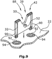
- Fig. 9 a possibility of electrical contacting (and mechanical support) of the sensor board 32 on the main circuit board 22.
- Die Sensorelektroden 42, oom der Fig. 9 such as in the FIGS. 1 and 2 are shown are connected via conductor tracks, which are formed on one of the two major side surfaces of the sensor board 32, with protruding Anchfussbeinchen 90 of the sensor board 32, which are immersed in recesses 92 of the main circuit board 22 and soldered to contact pads 94, for example, around the recesses 92 are arranged around.
Landscapes
- Engineering & Computer Science (AREA)
- Chemical & Material Sciences (AREA)
- Combustion & Propulsion (AREA)
- Transportation (AREA)
- Mechanical Engineering (AREA)
- Switches That Are Operated By Magnetic Or Electric Fields (AREA)
Claims (9)
- Unité de commande pour un appareil de véhicule, notamment pour une radio, un lecteur de CD et/ou de DVD, un appareil de navigation, un appareil d'information et de divertissement, un appareil de commande de chauffage ou de climatisation, ou pour une interface homme-machine, avec- une paroi avant (12) sur laquelle est disposé au moins un champ de symbole (20) et- un détecteur de proximité (28) disposé derrière la paroi avant (12) et associé au champ de symbole (20), pour la détection d'un contact avec le champ de symbole (20) par un objet, notamment par le doigt d'une main,- le détecteur de proximité (28) comprenant un corps de support de détecteur (30) avec une platine de détecteur (32) et au moins une électrode de détecteur (42),caractérisée en ce que- la platine de détecteur (32) comporte une zone de bord (39) pour électrode de détecteur qui est formée par une surface de bord (38) reliant entre elles les deux surfaces latérales principales opposées (34, 36) de la platine de détecteur (32) et par les zones attenantes à celles-ci des surfaces latérales principales (34, 36) et- en ce que ladite au moins une électrode de détecteur comporte une surface (40) électriquement conductrice qui s'étend sur la zone de bord (39) pour électrode de détecteur à l'extérieur sur les deux surfaces latérales principales opposées (34, 36) et à l'extérieur sur la surface de bord (38) reliant entre elles les deux surfaces latérales principales opposées (34, 36) de la platine de détecteur (32),- la platine de détecteur (32) s'étendant sensiblement perpendiculairement à l'étendue de la paroi avant (12) et une surface de bord (38) de la platine de détecteur (32) reliant entre elles les deux surfaces latérales principales opposées (34, 36) de la platine de détecteur (32) étant la zone la plus proche de la paroi avant (12) et étant orientée vers le champ de symbole.
- Unité de commande selon la revendication 1, caractérisée en ce que ledit au moins un champ de symbole (20) est formé sur un corps de bouton-poussoir (16) d'un bouton-poussoir (14) disposé sur la paroi avant (12) et en ce que la platine de détecteur (32) est disposée dans le corps de bouton-poussoir (16).
- Unité de commande selon la revendication 1 ou 2, caractérisée en ce que plusieurs champs de symbole (20) sont disposés sur la paroi avant (12) les uns à côté ou au-dessus des autres et en ce que la zone de bord (39) pour électrode de détecteur de la platine de détecteur (32) s'étend le long des champs de symbole (20) et comprend au moins une électrode de détecteur (42) pour chaque champ de symbole (20).
- Unité de commande selon la revendication 2 et 3, caractérisée en ce que les plusieurs champs de symbole (20) sont disposés sur le corps de bouton-poussoir (16).
- Unité de commande selon l'une des revendications 1 à 4, caractérisée en ce que la zone de bord (39) pour électrode de détecteur de la platine de détecteur (32) comprend un évidement de bord (50) avec une portion de bord en retrait par rapport à l'électrode de détecteur (42) et en ce qu'il est disposé sur au moins une des deux surfaces latérales principales opposées (34, 36) de la platine de détecteur (32) proche de la portion de bord en retrait, une source lumineuse de rétro-éclairage de champ de symbole (52) ayant un axe optique principal d'émission de lumière qui s'étend sensiblement parallèlement à l'étendue de la platine de détecteur (32) et au-delà de la portion de bord en retrait.
- Unité de commande selon l'une des revendications 1 à 5, caractérisée en ce qu'une électrode de blindage (62) est formée sur la platine de détecteur (32), qui est associée à une électrode de détecteur (42) ou à plusieurs électrodes de détecteur (42).
- Unité de commande selon l'une des revendications 1 à 6, caractérisée en ce que, sur la zone de bord (39) pour électrode de détecteur de la platine de détecteur (32), pour agrandir la surface de détecteur (40, 42) de l'électrode de détecteur (42), électriquement conductrice et orientée vers le champ de symbole (20), un composant (60, 70, 80) comportant un matériau électriquement conducteur est enfiché ou est relié d'une autre manière à la zone de bord (39) pour électrode de détecteur de la platine de détecteur (32) tout en s'étendant sensiblement transversalement aux surfaces principales (34, 36) de la platine de détecteur (32) et au-delà des deux surfaces principales (34, 36) opposées.
- Unité de commande selon l'une des revendications 1 à 7, caractérisée en ce que la platine de détecteur (32) comprend des champs de connexion pour une connexion électrique de l'électrode de détecteur (42) et, le cas échéant, de l'électrode de blindage (62), avec une plaque de support.
- Unité de commande selon la revendication 8, caractérisée en ce que les champs de connexion sont conformés pour être connectés de manière électriquement conductrice à des éléments formant broches d'enfichage ou douilles d'enfichage d'un connecteur de câble, ou sont disposés sur des saillies de bord de la platine de conducteur de détecteur pour plonger dans des prises de contact ou des évidements de contact (92) de la plaque de support (22).
Applications Claiming Priority (2)
| Application Number | Priority Date | Filing Date | Title |
|---|---|---|---|
| DE102011008509A DE102011008509A1 (de) | 2011-01-13 | 2011-01-13 | Bedieneinheit für eine Fahrzeugkomponente |
| PCT/EP2012/050452 WO2012095496A1 (fr) | 2011-01-13 | 2012-01-12 | Unité de commande pour un appareil de véhicule |
Publications (2)
| Publication Number | Publication Date |
|---|---|
| EP2664065A1 EP2664065A1 (fr) | 2013-11-20 |
| EP2664065B1 true EP2664065B1 (fr) | 2016-05-04 |
Family
ID=45524525
Family Applications (1)
| Application Number | Title | Priority Date | Filing Date |
|---|---|---|---|
| EP12700806.8A Active EP2664065B1 (fr) | 2011-01-13 | 2012-01-12 | Unité de commande pour un appareil de véhicule |
Country Status (3)
| Country | Link |
|---|---|
| EP (1) | EP2664065B1 (fr) |
| DE (1) | DE102011008509A1 (fr) |
| WO (1) | WO2012095496A1 (fr) |
Families Citing this family (1)
| Publication number | Priority date | Publication date | Assignee | Title |
|---|---|---|---|---|
| IT201800007044A1 (it) * | 2018-07-09 | 2020-01-09 | Tastiera capacitiva |
Family Cites Families (9)
| Publication number | Priority date | Publication date | Assignee | Title |
|---|---|---|---|---|
| DE4027761A1 (de) * | 1990-09-01 | 1992-03-12 | Steinmueller Kg Atlanta Kabel | Funkentstoerelement und tragplatte |
| DE10250395A1 (de) * | 2002-10-29 | 2004-05-13 | BSH Bosch und Siemens Hausgeräte GmbH | Kapazitiver Annäherungs- und/oder Berührungssensor sowie elektrisch leitfähiger Kunststoffkörper für einen solchen Sensor |
| DE102005025021A1 (de) * | 2005-05-30 | 2006-12-07 | Intedis Gmbh & Co. Kg | Schalterelement |
| DE102005029503A1 (de) | 2005-06-24 | 2006-12-28 | Siemens Ag | Bedienelement mit Näherungssensor und Abschirmung |
| DE102005029512A1 (de) | 2005-06-24 | 2006-12-28 | Siemens Ag | Bedienelement mit Näherungssensor |
| DE102007025564A1 (de) | 2006-06-07 | 2007-12-13 | Preh Gmbh | Bedienelement für ein Kraftfahrzeug |
| DE102006035837A1 (de) | 2006-08-01 | 2008-02-07 | Siemens Ag | Bedienelement |
| US20080053713A1 (en) * | 2006-08-30 | 2008-03-06 | High Tech Computer Corp. (A Legal Entity Of Taiwan) | Touch-sensitive input device and electronic device incorporating the touch-sensitive input device |
| US7772514B2 (en) * | 2007-12-20 | 2010-08-10 | Verifone, Inc. | Capacitive user-interface switches |
-
2011
- 2011-01-13 DE DE102011008509A patent/DE102011008509A1/de not_active Withdrawn
-
2012
- 2012-01-12 EP EP12700806.8A patent/EP2664065B1/fr active Active
- 2012-01-12 WO PCT/EP2012/050452 patent/WO2012095496A1/fr not_active Ceased
Also Published As
| Publication number | Publication date |
|---|---|
| DE102011008509A1 (de) | 2012-07-19 |
| WO2012095496A1 (fr) | 2012-07-19 |
| EP2664065A1 (fr) | 2013-11-20 |
Similar Documents
| Publication | Publication Date | Title |
|---|---|---|
| EP2853027B1 (fr) | Agencement avec dispositif a element capteur sur un support de composants pour un commutateur tactile capacitif d'un dispositif de commande, dispositif de commande et plaque de cuisson avec un tel agencement | |
| DE102006063082B3 (de) | Zweidimensionaler Positionssensor | |
| DE102010045194B4 (de) | Kapazitive Tastfeld-Eingabevorrichtung und damit ausgestattetes Gerät | |
| EP3028127B1 (fr) | Dispositif d'entrée sensible à la proximité et/ou au contact | |
| EP2355356B1 (fr) | Commutateur de contact et/ou de rapprochement capacitif | |
| EP2759060B1 (fr) | Dispositif de commande, par exemple interface homme-machine, en particulier pour un composant de véhicule | |
| DE102010047686B4 (de) | Elektrostatische kapazitive Tastfeld-Eingabevorrichtung | |
| DE202024105266U1 (de) | Kapazitive Bedieneinheit | |
| DE102017218243B3 (de) | Verfahren zum Herstellen zumindest eines Teils einer berührungssensitiven Bedieneinrichtung, berührungssensitive Bedieneinrichtung und Kraftfahrzeug | |
| DE102016112202A1 (de) | Anzeigefeld und Anzeigevorrichtung | |
| EP2207075A2 (fr) | Dispositif d'entrée sensible au contact | |
| DE102010033390B4 (de) | Kapazitiver Berührungs- und/oder Annäherungsschalter | |
| DE102011122110B4 (de) | Bedienvorrichtung mit Anzeigeeinrichtung und Tastfeldeinrichtung, sowie Mehrschichtkörper zur Bereitstellung einer Tastfeldfunktionalität | |
| DE202007018958U1 (de) | Berührungsbildschirm | |
| WO2018234362A1 (fr) | Dispositif de commande de véhicule à moteur | |
| EP2664065B1 (fr) | Unité de commande pour un appareil de véhicule | |
| WO2018172085A1 (fr) | Appareil électroménager comportant un écran tactile capacitif blindé contre les interférences électromagnétiques et procédé pour le réaliser | |
| DE102010005663A1 (de) | Kapazitiver Berührungs- und/oder Annäherungsschalter | |
| DE102010026181A1 (de) | Bedieneinheit für ein Fahrzeug | |
| DE102016124503B4 (de) | Bedienvorrichtung für ein Kraftfahrzeug mit einer konfigurierbaren Leiterplatte | |
| DE102008014463A1 (de) | Bedieneinheit für eine Fahrzeugkomponente, insbesondere für eine Belüftungs- und/oder Klimaanlage eines Fahrzeuges | |
| EP2645002B1 (fr) | Plaque de cuisson | |
| EP4734374A2 (fr) | Dispositif de commande pour un appareil électrique et appareil électrique doté d'un tel dispositif de commande | |
| EP2017692B1 (fr) | Boîtier d'ordinateur | |
| DE102011016504B4 (de) | Anzeigevorrichtung für eine Fahrzeugkomponente |
Legal Events
| Date | Code | Title | Description |
|---|---|---|---|
| PUAI | Public reference made under article 153(3) epc to a published international application that has entered the european phase |
Free format text: ORIGINAL CODE: 0009012 |
|
| 17P | Request for examination filed |
Effective date: 20130702 |
|
| AK | Designated contracting states |
Kind code of ref document: A1 Designated state(s): AL AT BE BG CH CY CZ DE DK EE ES FI FR GB GR HR HU IE IS IT LI LT LU LV MC MK MT NL NO PL PT RO RS SE SI SK SM TR |
|
| DAX | Request for extension of the european patent (deleted) | ||
| GRAP | Despatch of communication of intention to grant a patent |
Free format text: ORIGINAL CODE: EPIDOSNIGR1 |
|
| INTG | Intention to grant announced |
Effective date: 20151111 |
|
| GRAS | Grant fee paid |
Free format text: ORIGINAL CODE: EPIDOSNIGR3 |
|
| GRAA | (expected) grant |
Free format text: ORIGINAL CODE: 0009210 |
|
| AK | Designated contracting states |
Kind code of ref document: B1 Designated state(s): AL AT BE BG CH CY CZ DE DK EE ES FI FR GB GR HR HU IE IS IT LI LT LU LV MC MK MT NL NO PL PT RO RS SE SI SK SM TR |
|
| REG | Reference to a national code |
Ref country code: GB Ref legal event code: FG4D Free format text: NOT ENGLISH |
|
| REG | Reference to a national code |
Ref country code: CH Ref legal event code: EP |
|
| REG | Reference to a national code |
Ref country code: AT Ref legal event code: REF Ref document number: 797692 Country of ref document: AT Kind code of ref document: T Effective date: 20160515 |
|
| REG | Reference to a national code |
Ref country code: IE Ref legal event code: FG4D Free format text: LANGUAGE OF EP DOCUMENT: GERMAN |
|
| REG | Reference to a national code |
Ref country code: DE Ref legal event code: R096 Ref document number: 502012006993 Country of ref document: DE |
|
| REG | Reference to a national code |
Ref country code: NL Ref legal event code: MP Effective date: 20160504 |
|
| REG | Reference to a national code |
Ref country code: LT Ref legal event code: MG4D |
|
| PG25 | Lapsed in a contracting state [announced via postgrant information from national office to epo] |
Ref country code: NL Free format text: LAPSE BECAUSE OF FAILURE TO SUBMIT A TRANSLATION OF THE DESCRIPTION OR TO PAY THE FEE WITHIN THE PRESCRIBED TIME-LIMIT Effective date: 20160504 Ref country code: NO Free format text: LAPSE BECAUSE OF FAILURE TO SUBMIT A TRANSLATION OF THE DESCRIPTION OR TO PAY THE FEE WITHIN THE PRESCRIBED TIME-LIMIT Effective date: 20160804 Ref country code: LT Free format text: LAPSE BECAUSE OF FAILURE TO SUBMIT A TRANSLATION OF THE DESCRIPTION OR TO PAY THE FEE WITHIN THE PRESCRIBED TIME-LIMIT Effective date: 20160504 Ref country code: FI Free format text: LAPSE BECAUSE OF FAILURE TO SUBMIT A TRANSLATION OF THE DESCRIPTION OR TO PAY THE FEE WITHIN THE PRESCRIBED TIME-LIMIT Effective date: 20160504 |
|
| PG25 | Lapsed in a contracting state [announced via postgrant information from national office to epo] |
Ref country code: ES Free format text: LAPSE BECAUSE OF FAILURE TO SUBMIT A TRANSLATION OF THE DESCRIPTION OR TO PAY THE FEE WITHIN THE PRESCRIBED TIME-LIMIT Effective date: 20160504 Ref country code: RS Free format text: LAPSE BECAUSE OF FAILURE TO SUBMIT A TRANSLATION OF THE DESCRIPTION OR TO PAY THE FEE WITHIN THE PRESCRIBED TIME-LIMIT Effective date: 20160504 Ref country code: HR Free format text: LAPSE BECAUSE OF FAILURE TO SUBMIT A TRANSLATION OF THE DESCRIPTION OR TO PAY THE FEE WITHIN THE PRESCRIBED TIME-LIMIT Effective date: 20160504 Ref country code: PT Free format text: LAPSE BECAUSE OF FAILURE TO SUBMIT A TRANSLATION OF THE DESCRIPTION OR TO PAY THE FEE WITHIN THE PRESCRIBED TIME-LIMIT Effective date: 20160905 Ref country code: LV Free format text: LAPSE BECAUSE OF FAILURE TO SUBMIT A TRANSLATION OF THE DESCRIPTION OR TO PAY THE FEE WITHIN THE PRESCRIBED TIME-LIMIT Effective date: 20160504 Ref country code: GR Free format text: LAPSE BECAUSE OF FAILURE TO SUBMIT A TRANSLATION OF THE DESCRIPTION OR TO PAY THE FEE WITHIN THE PRESCRIBED TIME-LIMIT Effective date: 20160805 Ref country code: SE Free format text: LAPSE BECAUSE OF FAILURE TO SUBMIT A TRANSLATION OF THE DESCRIPTION OR TO PAY THE FEE WITHIN THE PRESCRIBED TIME-LIMIT Effective date: 20160504 |
|
| PG25 | Lapsed in a contracting state [announced via postgrant information from national office to epo] |
Ref country code: IT Free format text: LAPSE BECAUSE OF FAILURE TO SUBMIT A TRANSLATION OF THE DESCRIPTION OR TO PAY THE FEE WITHIN THE PRESCRIBED TIME-LIMIT Effective date: 20160504 |
|
| PG25 | Lapsed in a contracting state [announced via postgrant information from national office to epo] |
Ref country code: CZ Free format text: LAPSE BECAUSE OF FAILURE TO SUBMIT A TRANSLATION OF THE DESCRIPTION OR TO PAY THE FEE WITHIN THE PRESCRIBED TIME-LIMIT Effective date: 20160504 Ref country code: DK Free format text: LAPSE BECAUSE OF FAILURE TO SUBMIT A TRANSLATION OF THE DESCRIPTION OR TO PAY THE FEE WITHIN THE PRESCRIBED TIME-LIMIT Effective date: 20160504 Ref country code: RO Free format text: LAPSE BECAUSE OF FAILURE TO SUBMIT A TRANSLATION OF THE DESCRIPTION OR TO PAY THE FEE WITHIN THE PRESCRIBED TIME-LIMIT Effective date: 20160504 Ref country code: SK Free format text: LAPSE BECAUSE OF FAILURE TO SUBMIT A TRANSLATION OF THE DESCRIPTION OR TO PAY THE FEE WITHIN THE PRESCRIBED TIME-LIMIT Effective date: 20160504 Ref country code: EE Free format text: LAPSE BECAUSE OF FAILURE TO SUBMIT A TRANSLATION OF THE DESCRIPTION OR TO PAY THE FEE WITHIN THE PRESCRIBED TIME-LIMIT Effective date: 20160504 |
|
| REG | Reference to a national code |
Ref country code: DE Ref legal event code: R097 Ref document number: 502012006993 Country of ref document: DE |
|
| PG25 | Lapsed in a contracting state [announced via postgrant information from national office to epo] |
Ref country code: SM Free format text: LAPSE BECAUSE OF FAILURE TO SUBMIT A TRANSLATION OF THE DESCRIPTION OR TO PAY THE FEE WITHIN THE PRESCRIBED TIME-LIMIT Effective date: 20160504 Ref country code: PL Free format text: LAPSE BECAUSE OF FAILURE TO SUBMIT A TRANSLATION OF THE DESCRIPTION OR TO PAY THE FEE WITHIN THE PRESCRIBED TIME-LIMIT Effective date: 20160504 |
|
| PLBE | No opposition filed within time limit |
Free format text: ORIGINAL CODE: 0009261 |
|
| STAA | Information on the status of an ep patent application or granted ep patent |
Free format text: STATUS: NO OPPOSITION FILED WITHIN TIME LIMIT |
|
| 26N | No opposition filed |
Effective date: 20170207 |
|
| PG25 | Lapsed in a contracting state [announced via postgrant information from national office to epo] |
Ref country code: SI Free format text: LAPSE BECAUSE OF FAILURE TO SUBMIT A TRANSLATION OF THE DESCRIPTION OR TO PAY THE FEE WITHIN THE PRESCRIBED TIME-LIMIT Effective date: 20160504 Ref country code: BE Free format text: LAPSE BECAUSE OF NON-PAYMENT OF DUE FEES Effective date: 20170131 |
|
| REG | Reference to a national code |
Ref country code: CH Ref legal event code: PL |
|
| GBPC | Gb: european patent ceased through non-payment of renewal fee |
Effective date: 20170112 |
|
| PG25 | Lapsed in a contracting state [announced via postgrant information from national office to epo] |
Ref country code: MC Free format text: LAPSE BECAUSE OF FAILURE TO SUBMIT A TRANSLATION OF THE DESCRIPTION OR TO PAY THE FEE WITHIN THE PRESCRIBED TIME-LIMIT Effective date: 20160504 |
|
| REG | Reference to a national code |
Ref country code: FR Ref legal event code: ST Effective date: 20170929 |
|
| PG25 | Lapsed in a contracting state [announced via postgrant information from national office to epo] |
Ref country code: FR Free format text: LAPSE BECAUSE OF NON-PAYMENT OF DUE FEES Effective date: 20170131 Ref country code: CH Free format text: LAPSE BECAUSE OF NON-PAYMENT OF DUE FEES Effective date: 20170131 Ref country code: LI Free format text: LAPSE BECAUSE OF NON-PAYMENT OF DUE FEES Effective date: 20170131 |
|
| REG | Reference to a national code |
Ref country code: IE Ref legal event code: MM4A |
|
| PG25 | Lapsed in a contracting state [announced via postgrant information from national office to epo] |
Ref country code: LU Free format text: LAPSE BECAUSE OF NON-PAYMENT OF DUE FEES Effective date: 20170112 Ref country code: GB Free format text: LAPSE BECAUSE OF NON-PAYMENT OF DUE FEES Effective date: 20170112 |
|
| REG | Reference to a national code |
Ref country code: BE Ref legal event code: MM Effective date: 20170131 |
|
| PG25 | Lapsed in a contracting state [announced via postgrant information from national office to epo] |
Ref country code: IE Free format text: LAPSE BECAUSE OF NON-PAYMENT OF DUE FEES Effective date: 20170112 |
|
| REG | Reference to a national code |
Ref country code: AT Ref legal event code: MM01 Ref document number: 797692 Country of ref document: AT Kind code of ref document: T Effective date: 20170112 |
|
| PG25 | Lapsed in a contracting state [announced via postgrant information from national office to epo] |
Ref country code: AT Free format text: LAPSE BECAUSE OF NON-PAYMENT OF DUE FEES Effective date: 20170112 |
|
| PG25 | Lapsed in a contracting state [announced via postgrant information from national office to epo] |
Ref country code: MT Free format text: LAPSE BECAUSE OF FAILURE TO SUBMIT A TRANSLATION OF THE DESCRIPTION OR TO PAY THE FEE WITHIN THE PRESCRIBED TIME-LIMIT Effective date: 20160504 |
|
| PG25 | Lapsed in a contracting state [announced via postgrant information from national office to epo] |
Ref country code: AL Free format text: LAPSE BECAUSE OF FAILURE TO SUBMIT A TRANSLATION OF THE DESCRIPTION OR TO PAY THE FEE WITHIN THE PRESCRIBED TIME-LIMIT Effective date: 20160504 |
|
| PG25 | Lapsed in a contracting state [announced via postgrant information from national office to epo] |
Ref country code: HU Free format text: LAPSE BECAUSE OF FAILURE TO SUBMIT A TRANSLATION OF THE DESCRIPTION OR TO PAY THE FEE WITHIN THE PRESCRIBED TIME-LIMIT; INVALID AB INITIO Effective date: 20120112 |
|
| PG25 | Lapsed in a contracting state [announced via postgrant information from national office to epo] |
Ref country code: BG Free format text: LAPSE BECAUSE OF FAILURE TO SUBMIT A TRANSLATION OF THE DESCRIPTION OR TO PAY THE FEE WITHIN THE PRESCRIBED TIME-LIMIT Effective date: 20160504 |
|
| PG25 | Lapsed in a contracting state [announced via postgrant information from national office to epo] |
Ref country code: CY Free format text: LAPSE BECAUSE OF NON-PAYMENT OF DUE FEES Effective date: 20160504 |
|
| PG25 | Lapsed in a contracting state [announced via postgrant information from national office to epo] |
Ref country code: MK Free format text: LAPSE BECAUSE OF FAILURE TO SUBMIT A TRANSLATION OF THE DESCRIPTION OR TO PAY THE FEE WITHIN THE PRESCRIBED TIME-LIMIT Effective date: 20160504 |
|
| PG25 | Lapsed in a contracting state [announced via postgrant information from national office to epo] |
Ref country code: TR Free format text: LAPSE BECAUSE OF FAILURE TO SUBMIT A TRANSLATION OF THE DESCRIPTION OR TO PAY THE FEE WITHIN THE PRESCRIBED TIME-LIMIT Effective date: 20160504 |
|
| PG25 | Lapsed in a contracting state [announced via postgrant information from national office to epo] |
Ref country code: IS Free format text: LAPSE BECAUSE OF FAILURE TO SUBMIT A TRANSLATION OF THE DESCRIPTION OR TO PAY THE FEE WITHIN THE PRESCRIBED TIME-LIMIT Effective date: 20160904 |
|
| REG | Reference to a national code |
Ref country code: DE Ref legal event code: R081 Ref document number: 502012006993 Country of ref document: DE Owner name: BEHR-HELLA THERMOCONTROL GMBH, DE Free format text: FORMER OWNER: BEHR-HELLA THERMOCONTROL GMBH, 70190 STUTTGART, DE |
|
| P01 | Opt-out of the competence of the unified patent court (upc) registered |
Free format text: CASE NUMBER: UPC_APP_329736/2023 Effective date: 20230524 |
|
| PGFP | Annual fee paid to national office [announced via postgrant information from national office to epo] |
Ref country code: DE Payment date: 20260120 Year of fee payment: 15 |