EP2664302A2 - Prothèse ou revêtement de prothèse - Google Patents
Prothèse ou revêtement de prothèse Download PDFInfo
- Publication number
- EP2664302A2 EP2664302A2 EP13167766.8A EP13167766A EP2664302A2 EP 2664302 A2 EP2664302 A2 EP 2664302A2 EP 13167766 A EP13167766 A EP 13167766A EP 2664302 A2 EP2664302 A2 EP 2664302A2
- Authority
- EP
- European Patent Office
- Prior art keywords
- prosthesis
- cover according
- finger
- layer
- input device
- Prior art date
- Legal status (The legal status is an assumption and is not a legal conclusion. Google has not performed a legal analysis and makes no representation as to the accuracy of the status listed.)
- Granted
Links
Images




Classifications
-
- A—HUMAN NECESSITIES
- A61—MEDICAL OR VETERINARY SCIENCE; HYGIENE
- A61F—FILTERS IMPLANTABLE INTO BLOOD VESSELS; PROSTHESES; DEVICES PROVIDING PATENCY TO, OR PREVENTING COLLAPSING OF, TUBULAR STRUCTURES OF THE BODY, e.g. STENTS; ORTHOPAEDIC, NURSING OR CONTRACEPTIVE DEVICES; FOMENTATION; TREATMENT OR PROTECTION OF EYES OR EARS; BANDAGES, DRESSINGS OR ABSORBENT PADS; FIRST-AID KITS
- A61F2/00—Filters implantable into blood vessels; Prostheses, i.e. artificial substitutes or replacements for parts of the body; Appliances for connecting them with the body; Devices providing patency to, or preventing collapsing of, tubular structures of the body, e.g. stents
- A61F2/50—Prostheses not implantable in the body
- A61F2/54—Artificial arms or hands or parts thereof
- A61F2/58—Elbows; Wrists ; Other joints; Hands
- A61F2/583—Hands; Wrist joints
-
- A—HUMAN NECESSITIES
- A61—MEDICAL OR VETERINARY SCIENCE; HYGIENE
- A61F—FILTERS IMPLANTABLE INTO BLOOD VESSELS; PROSTHESES; DEVICES PROVIDING PATENCY TO, OR PREVENTING COLLAPSING OF, TUBULAR STRUCTURES OF THE BODY, e.g. STENTS; ORTHOPAEDIC, NURSING OR CONTRACEPTIVE DEVICES; FOMENTATION; TREATMENT OR PROTECTION OF EYES OR EARS; BANDAGES, DRESSINGS OR ABSORBENT PADS; FIRST-AID KITS
- A61F2/00—Filters implantable into blood vessels; Prostheses, i.e. artificial substitutes or replacements for parts of the body; Appliances for connecting them with the body; Devices providing patency to, or preventing collapsing of, tubular structures of the body, e.g. stents
- A61F2/50—Prostheses not implantable in the body
- A61F2/54—Artificial arms or hands or parts thereof
- A61F2/58—Elbows; Wrists ; Other joints; Hands
- A61F2/583—Hands; Wrist joints
- A61F2/586—Fingers
-
- A—HUMAN NECESSITIES
- A61—MEDICAL OR VETERINARY SCIENCE; HYGIENE
- A61F—FILTERS IMPLANTABLE INTO BLOOD VESSELS; PROSTHESES; DEVICES PROVIDING PATENCY TO, OR PREVENTING COLLAPSING OF, TUBULAR STRUCTURES OF THE BODY, e.g. STENTS; ORTHOPAEDIC, NURSING OR CONTRACEPTIVE DEVICES; FOMENTATION; TREATMENT OR PROTECTION OF EYES OR EARS; BANDAGES, DRESSINGS OR ABSORBENT PADS; FIRST-AID KITS
- A61F4/00—Methods or devices enabling patients or disabled persons to operate an apparatus or a device not forming part of the body
-
- A—HUMAN NECESSITIES
- A61—MEDICAL OR VETERINARY SCIENCE; HYGIENE
- A61F—FILTERS IMPLANTABLE INTO BLOOD VESSELS; PROSTHESES; DEVICES PROVIDING PATENCY TO, OR PREVENTING COLLAPSING OF, TUBULAR STRUCTURES OF THE BODY, e.g. STENTS; ORTHOPAEDIC, NURSING OR CONTRACEPTIVE DEVICES; FOMENTATION; TREATMENT OR PROTECTION OF EYES OR EARS; BANDAGES, DRESSINGS OR ABSORBENT PADS; FIRST-AID KITS
- A61F2/00—Filters implantable into blood vessels; Prostheses, i.e. artificial substitutes or replacements for parts of the body; Appliances for connecting them with the body; Devices providing patency to, or preventing collapsing of, tubular structures of the body, e.g. stents
- A61F2/50—Prostheses not implantable in the body
- A61F2/68—Operating or control means
- A61F2/70—Operating or control means electrical
-
- A—HUMAN NECESSITIES
- A61—MEDICAL OR VETERINARY SCIENCE; HYGIENE
- A61F—FILTERS IMPLANTABLE INTO BLOOD VESSELS; PROSTHESES; DEVICES PROVIDING PATENCY TO, OR PREVENTING COLLAPSING OF, TUBULAR STRUCTURES OF THE BODY, e.g. STENTS; ORTHOPAEDIC, NURSING OR CONTRACEPTIVE DEVICES; FOMENTATION; TREATMENT OR PROTECTION OF EYES OR EARS; BANDAGES, DRESSINGS OR ABSORBENT PADS; FIRST-AID KITS
- A61F2/00—Filters implantable into blood vessels; Prostheses, i.e. artificial substitutes or replacements for parts of the body; Appliances for connecting them with the body; Devices providing patency to, or preventing collapsing of, tubular structures of the body, e.g. stents
- A61F2/50—Prostheses not implantable in the body
- A61F2002/5001—Cosmetic coverings
-
- A—HUMAN NECESSITIES
- A61—MEDICAL OR VETERINARY SCIENCE; HYGIENE
- A61F—FILTERS IMPLANTABLE INTO BLOOD VESSELS; PROSTHESES; DEVICES PROVIDING PATENCY TO, OR PREVENTING COLLAPSING OF, TUBULAR STRUCTURES OF THE BODY, e.g. STENTS; ORTHOPAEDIC, NURSING OR CONTRACEPTIVE DEVICES; FOMENTATION; TREATMENT OR PROTECTION OF EYES OR EARS; BANDAGES, DRESSINGS OR ABSORBENT PADS; FIRST-AID KITS
- A61F2/00—Filters implantable into blood vessels; Prostheses, i.e. artificial substitutes or replacements for parts of the body; Appliances for connecting them with the body; Devices providing patency to, or preventing collapsing of, tubular structures of the body, e.g. stents
- A61F2/50—Prostheses not implantable in the body
- A61F2002/5058—Prostheses not implantable in the body having means for restoring the perception of senses
- A61F2002/5061—Prostheses not implantable in the body having means for restoring the perception of senses the sense of touch
Definitions
- the invention relates to a prosthesis or a denture cover.
- Capacitive touch-sensitive input devices such as touchscreens respond to changes in the capacitance of the touch-sensitive surface and are generally operated with the naked finger or sometimes with electrically conductive tools such as electrically conductive styli. Especially the operation of a touch screen with the bare finger allows a simple, direct and direct interaction of the user with the object shown on the touch screen.
- capacitive input devices has particular disadvantages for people with, for example, finger or hand prostheses, since on the one hand such prostheses are generally made of an insulating material, such as silicone, which resembles the nature of the body part to be replaced in consistency and color. Leave capacitive input devices Therefore, do not use directly with the prosthesis. Also, the use of an electrically conductive stylus is problematic with a prosthesis, since the necessary for positioning the stylus fine motor movements are usually not accurate enough with the prosthesis executable.
- the invention described below makes it possible for people with, for example, a hand or finger prosthesis, to use capacitive input devices with smart technologies, such as for example capacitive touch screens of mobile phones or interactive display panels, without additional aids.
- the prosthesis or the prosthesis coating according to the invention has at least one region which is suitable for operating a capacitive input device, in particular a capacitive touch-sensitive input device.
- a region is understood to mean a part of the prosthesis which is in electrical and / or mechanical contact with the outer surface of the prosthesis or is part of the outer surface and can be brought into electrical and / or mechanical contact with objects from the environment of the prosthesis wearer.
- the prosthesis or the prosthesis coating has at least one first layer, this layer again serving as a region for operating the capacitive input device, a first contact point and an electrically conductively connected to the first contact point having second contact point.
- the first contact point can be brought into contact with the input device.
- the second contact point is in turn connected to a body part electrically conductive.
- the first and the second contact point are alternatively referred to as the first and second contact surface.
- the second contact point generally has an area of 1 to 100 mm 2 , advantageously of 5 to 50 mm 2 , advantageously of 20 to 40 mm 2 , advantageously of 30 mm 2 .
- the maximum possible area of the second contact point is limited, for example, by the shape of the surface of the body part with which the second contact point is electrically conductively connected.
- the first and / or the second contact point preferably contain conductive silicone and / or a conductive foam or consist thereof.
- first and second pads may be electrically conductive via a conductive substrate including or consisting of silicone, polyurethane, metals, conductive yarn, a conductive cable, a conductive liquid, a conductive channel, or other conductive materials or combinations thereof be connected to each other.
- a conductive substrate including or consisting of silicone, polyurethane, metals, conductive yarn, a conductive cable, a conductive liquid, a conductive channel, or other conductive materials or combinations thereof be connected to each other.
- the conductive support e.g. a cable or conductive channel advantageously has an average of between 1mm and 4mm, more preferably between 2mm and 3mm.
- the conductive carrier is part of the first layer. This enables a particularly secure and sustainable positioning of the conductive support, wherein the mechanical loads, e.g. caused by bending moments occurring during use of the prosthesis or denture cover.
- the prosthesis or prosthesis coating may also be at least an inner layer as the first layer and at least one second, outer layer, wherein the second layer largely surrounds the first layer except for the contact points.
- the contact points are thus not covered by the second layer, so that electrically conductive contacts between the first contact point and a capacitive input device and between the second contact point and a body part can be produced.
- the outer layer thus delimits the inner, first layer except for the contact points substantially against the environment, ie, to the outside.
- the outer and inner layers are thus arranged such that the inner layer is adjacent to the prosthesis accommodated by the prosthesis coating, and the outer layer is arranged substantially on the side of the inner layer facing away from the prosthesis.
- the second, outer layer is alternatively referred to as a second layer or as an outer layer.
- a capacitive input device can be operated by a patient with the same quality as with a healthy body part.
- the inner layer can be vulcanized into the outer layer and / or glued.
- the second layer is advantageously electrically non-conductive. Further, the second layer may contain a material similar in texture and / or color to the skin. It is also conceivable that the outer layer contains silicone or consists of more than 90% thereof. The first layer may also contain silicone or over 90% of it.
- the elasticity of silicone allows an adaptive behavior of the prosthesis or prosthesis coating. Furthermore, a dimensionally stable design of the prosthesis or the prosthesis cover with free color design allows. Due to its high silicone content, the prosthesis or prosthesis cover is of a high mechanical quality and is very comfortable to wear.
- the prosthesis or the prosthesis coating as a region for operating a capacitive input device on a contact point which is alternatively referred to below as a contact surface, which is electrically connected to an input unit.
- the input unit is preferably attached to the prosthesis or prosthesis cover by means of an adhesive connection.
- the input unit can also be attached by means of a cuff to the prosthesis or to the prosthesis cover.
- the input unit may also be formed pin-shaped.
- the input unit and / or the pad contains or consists of conductive silicone and / or a conductive foam.
- the area for operating the capacitive input device preferably has an area of 1 to 100 mm 2 , advantageously of 5 to 50 mm 2 , advantageously of 20 to 30 mm 2 , advantageously of 25 mm 2 . In this case, a smaller area is particularly advantageous since this increases the positioning accuracy on a touch-sensitive input device.
- the prosthesis or denture cover contains or consists of high temperature crosslinked silicone as the base material. Furthermore, the area for operating the capacitive input device may be coated with a thin, optionally color-adapted, material for protecting the area.
- the above-described prosthesis according to the invention or the prosthesis cover according to the invention described above is suitable for operating a touchscreen, touch display, touchpad, touch mouse and / or multi-touch surface and can be used as finger, hand, partial hand, arm, foot , Leg or toe prosthesis or as a cover for a finger, fland, partial hand, Arm, foot, leg, toe prosthesis or a work prosthesis hand, such as a hook prosthesis, be formed, wherein the second contact point with a finger, hand, arm, leg, toe or toe stump is electrically connected ,
- the input units used here are capacitive input units. If the contact surface of the input unit is brought into contact with, for example, a capacitive touch display, the capacitance in the touch display changes at the contact position, that is to say the position of the touch display, which is in contact with the contact surface. The contact position at which the capacitance changes can then be determined via a current and / or voltage measurement.
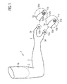
- FIG. 1 shows an inventive Elbow disarticulation and / or upper arm prosthesis 1 for operating a capacitive touch-sensitive input device according to a first embodiment.
- the prosthesis 1 has an upper arm part 2, a lower arm part 3 and a hand part 4.
- the upper arm part has a prosthesis shaft 7a with an approximately cylindrical cavity open towards the imaginary shoulder which, depending on the length of the amputation stump, reaches as far as the prosthetic elbow joint.
- the prosthesis stem 7a is suitable for receiving a human upper arm stump largely in a form-fitting manner.
- the handpiece 4 of the prosthesis 1 has an artificial thumb 5a and artificial fingers 5b, only an index finger being shown here for the sake of simplicity.
- the thumb 5a and the fingers 5b are provided at their tips facing away from the hand part 4 in the region of the thumb or finger pressure surfaces 54a and 54b with contact surfaces 11a and 11b.
- On a side facing away from the finger 5b or thumb 5a of the contact surface 11b and 11a are respectively input units 10b and 10a, which are in electrically conductive contact with the contact surfaces 11b and 11a.
- the input units 10b and 10a are preferably formed tapering away from the contact surfaces 11b and 11a, respectively.
- the input units 10a and 10b can be brought into electrically conductive contact with a surface of the input device. The smaller the contact surface of the input unit, the more precise the input device can be operated. It is also conceivable to equip only individual fingers 5b or only the thumb 5a with contact surfaces 11b and 11a.
- Various types of multi-touch commands are possible on multi-touch enabled input devices.
- FIG. 2 shows a Schulterexartikulations- and shoulder girdle prosthesis 1 according to the invention according to a first embodiment.
- the prosthesis 1 comprises a shoulder part 8, an upper arm part 2, a lower arm part 3 and a hand part 4.
- the shoulder part 8 is largely formed as a prosthesis shaft 7b, which is suitable for receiving a human shoulder stump.
- the design of the prosthesis stem 7b can be made flat or in frame construction.
- the shoulder portion 8 covers the human shoulder approximately to the neck.
- the shoulder part 8 is adjoined by the upper arm part 2 of the prosthesis 1.
- the forearm part 3 and the hand part 4 are as in FIG. 1 described constructed.
- the handpiece 4 has an artificial thumb 5a and artificial fingers 5b, wherein only an index finger is shown here for the sake of simplicity.
- the thumb 5a and the fingers 5b have at their ends facing away from the hand part 4 finger end members 53a and 53b. At these finger end links 53a and 53b, the thumb 5a and the fingers 5b in the area of the thumb or finger pressure surfaces 54a and 54b are provided with contact surfaces 11a and 11b, respectively, which have input units 10a and 10a on their sides facing away from the thumb 5a and the fingers 5b, respectively. 10b have.
- the input units 10a and 10b are electrically conductively connected to the contact surfaces 11a and 11b, respectively.
- the input units 10a and 10b are advantageously designed tapering away from the thumb 5a or away from the fingers 5b.
- the input units 10a and 10b are brought into electrically conductive contact with a surface of the input device.
- FIG. 1 It is also conceivable here to provide only the thumb 5a and / or individual fingers 5b with contact surfaces 11a and 11b.
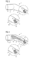
- FIG. 3 shows an inventive finger prosthesis 1 according to a first embodiment in the form of an artificial finger 5 with a first finger member 51, a second finger member 52 and a finger end member 53.
- the finger prosthesis has a prosthesis shank 7c, which has an approximately cylindrical cavity, the approach to the artificial finger 5 is open and extends along the first artificial finger member 51.
- the prosthesis shaft 7c is suitable for precisely fitting a human finger stump.
- a contact surface 11 which has an input unit 10 on its side facing away from the finger 5.
- the input unit 10 is electrically conductively connected to the contact surface 11.
- the input unit 10 can thus be used to operate a capacitive touch-sensitive input device, wherein between the input unit 10 and a surface of the input device, an electrically conductive contact is made.
- FIG. 4 shows a further variant of a finger prosthesis 1 according to the invention according to a first embodiment. This is largely like the finger prosthesis in FIG. 3 built up. In contrast to the finger prosthesis in FIG. 3 has the finger prosthesis 1 in FIG. 4 inside a cavity 6, which extends over the entire second finger member 52 of the artificial finger 5 and viewed from a second finger member 52 to approximately one third of the length of the first finger member 51 and the finger end member 53 respectively in the first finger member 51 and the finger end member 53 protrudes.
- FIG. 5 shows a partial hand prosthesis 1 according to the invention according to a first embodiment.
- the prosthesis 1 has a hand part 4, a thumb 5a and fingers 5b, wherein only an index finger is shown here for the sake of simplicity.
- the handpiece 4 as well as the form attachments of existing finger stumps, such as here the first finger members 51a and 51b of the thumb 5a and the fingers 5b, form a prosthesis shaft 7d, which is suitable for precisely fitting a hand with finger stumps or still existing individual fingers ,
- the finger end members 53a and 53b are provided with contact surfaces 11a and 11b, on whose sides facing away from the thumb 5a or the fingers 5b, input units 10a and 10b are arranged.
- the input units 10a and 10b can be brought into electrically conductive contact with a surface of the input device.
- the thumb 5a and / or individual fingers 5b with contact surfaces equip.
- FIG. 6 shows a hand prosthesis 1 according to the invention according to a first embodiment with a handle 4, an artificial thumb 5a and artificial fingers 5b.
- the handpiece 4 is formed as a prosthesis shaft 7e with an imaginary forearm towards open, approximately cylindrical cavity, which extends to the base of the artificial thumb 5a and the artificial finger 5b.
- the prosthesis stem 7e is different from the prosthetic stem 7d in FIG FIG. 5 suitable for accurate recording of a transcarpal and stump without finger stumps.
- the thumb 5a and the fingers 5b in the area of the finger pressure surfaces 54a and 54b of the finger end members 53a and 53b respectively are provided with contact surfaces, which in turn comprise the input units 10a and 10b.
- FIG. 7 shows a forearm prosthesis 1 according to the invention according to a first embodiment with a forearm part 3, a handpiece 4 and artificial fingers 5a and 5b, wherein here for simplicity only the thumb 5a and the index finger 5b are shown.
- the forearm part has a condyle-free or condyle-encompassing prosthesis stem 7f that extends from an imaginary elbow joint along about half of the forearm part.
- the prosthesis shaft 7f is suitable for precisely fitting a forearm stump.
- contact surfaces 11a and 11b with input units 10a and 10b are arranged on the thumb 5a and on the fingers 5b, with the input units 10a and 10b being in electrically conductive contact with the contact surfaces.
- the input units 10a and 10b can be brought into electrically conductive contact with a surface of the input device.
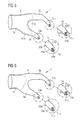
- FIG. 8 shows an elbow disarticulation and / or Upper arm prosthesis 1 as in FIG. 1 according to a second embodiment.
- the thumb 5a and the fingers 5b are provided at their tips facing away from the hand part 4 in the region of the thumb or finger pressure surfaces 54a and 54b with first contact surfaces 16a and 16b.
- the contact surfaces 16a and 16b are tapered or hemispherical on their side remote from the tip of the thumb or fingertip.
- the first contact surfaces 16a and 16b are each electrically conductively connected to electrically conductive channels 13a and 13b extending from the first contact surfaces 16a and 16b along the thumb 5a and the fingers 5b in the handpiece 4 and in the handpiece 4 in a Mouth 14 converge to an electrically conductive channel 13.
- the channel 13 extends from the mouth 14 along the forearm part 13 to a branch point 15 in the area of the prosthetic elbow joint.
- the channel 13 divides into three electrically conductive channels 13I, 13II, 13III which extend along the upper arm part 2 to the lower region of the prosthesis shaft 7a facing the prosthetic elbow joint.
- the second contact surfaces 12 are further arranged on the prosthesis shaft 7a such that they are in electrically conductive contact with an upper arm stump during the wearing of the prosthesis 1.
- FIG. 9 shows a shoulder disarticulation and shoulder girdle prosthesis 1 according to the invention as in FIG. 2 according to a second embodiment.
- the handpiece 4 and the forearm part 3 are as in FIG. 8 built up.
- the electrically conductive channel 13 extends further into the upper arm part 2, so that the branching point 15 is located in the region of the upper arm part 2 adjoining the shoulder.
- the channel 13 is divided into three channels 13I, 13 II and 13 III, which in turn extend to the prosthesis shaft 7b.
- three second contact surfaces 12 are arranged approximately maximally spaced from one another.
- Each of these three second contact surfaces 12 is in each case electrically conductively connected to one of the channels 13I, 13II and 13III.
- the second contact surfaces 12 are further arranged on the prosthesis shaft 7b such that they are in electrically conductive contact with a shoulder stump during the wearing of the prosthesis 1.
- an electrical contact during wearing of the prosthesis 1 between the first contact surfaces 16a and 16b and a shoulder stump via the channels 13a and 13b, 13 and 13I, 13II, 13III and the second contact surfaces 12, an electrical contact.
- FIG. 10 shows an inventive finger prosthesis 1 as in FIG. 3 according to a second embodiment.
- the finger prosthesis 1 in FIG. 10 in the region of the finger pressure surface 54, a first contact surface 16, which is electrically conductively connected to an electrically conductive channel 13.
- the contact surface 16 is tapered or hemispherical on its side facing away from the fingertip.
- the channel 13 extends from the first contact surface 16 along the finger end member 53 to a branch point 15 in the region between the second finger member 52 and the finger end member 53.
- the channel 13 is divided into three channels 13I, 13II and 13 III, extending from the branch point 15 along the second phalange 52 to the prosthesis stem 7c.
- three second contact surfaces 12 are arranged approximately at a maximum distance from one another and are each electrically conductively connected to one of the channels 13I, 13II and 13III.
- the second contact surfaces 12 are arranged on the prosthesis shaft 7c such that the second contact surfaces 12 are in electrically conductive contact with a finger stump when the prosthesis 1 is worn.
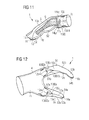
- FIG. 11 shows a further finger prosthesis 1 according to the invention as in FIG. 4 according to a second embodiment.
- the finger prosthesis in FIG. 11 in the area of the finger pressure surface 54 provided with a first contact surface 16.
- This is electrically conductively connected to an electrically conductive channel 13.
- On the side of the first contact surface 16 facing away from the fingertip there is a branching point 15 in which the channel 13 splits into two electrically conductive channels 13x and 13y.
- the channel 13x extends above the cavity 6, ie in the region of the finger back, along the finger end member 53 and the second finger member 52 to an opening 14xz approximately in the region of half of the first finger member 51.
- the channel 13y extends below the cavity 6, so in the region of the inner surface of the finger along the finger end member 53 and the second finger member 52 to an opening 14yz approximately in the region of half of the first finger member 51.
- the mouths 14xz and 14yz are on the prosthesis shaft 7c side facing by a channel 13z electrically connected to each other. From the mouth 14xz, a channel 13I extends to the prosthesis stem 7c, from the mouth 14yz a channel 13III extends to the prosthesis stem 7c and from a middle length of the channel 13z located mouth 14zz, the channel 13III extends to the prosthesis stem 7c , In the region of the prosthesis shaft 7c facing the cavity 6, three second contact surfaces 12 are arranged approximately at a maximum distance from one another.
- Each of the three second contact surfaces 12 is in each case electrically conductively connected to one of the channels 13I, 13II and 13III.
- the second contact surfaces 12 are arranged on the prosthesis shaft 7c in such a way that a finger stub is in electrical contact with the second contact surfaces 12 during the wearing of the prosthesis 1.
- FIG. 12 shows a Partialhandprothese 1 according to the invention as in FIG. 5 according to a second embodiment.
- the prosthesis 1 in FIG. 12 in the region of the thumb and finger pressure surfaces 54a and 54b first contact surfaces 16a and 16b.
- the first contact surfaces 16a and 16b are each electrically conductively connected to an electrically conductive channel 13a or 13b.
- the channels 13a and 13b respectively extend from the first contact surfaces 16a and 16b along the finger-end members 53a and 53b and along the second 52a and 52b and the first Finger members 51a and 51b, respectively, to branch points 15a and 15b in the central portions of the first finger members 51a and 51.
- the channels 13a and 13b are respectively divided into three channels 13Ia, 13IIa, 13IIIa and 13Ib, 13IIb, 13IIIb, which in turn extend to the respective fingers 5b and thumb 5a facing areas of the prosthesis stem 7d.
- On the fingers 5b and the thumb 5a facing areas of the prosthesis stem 7d each have three second contact surfaces 12a and 12b are arranged.
- the second contact surfaces 12a are electrically connected to a respective one of the channels 13Ia, 13IIa and 13IIIa.
- the second contact surfaces 12b are electrically conductively connected to a respective one of the channels 13Ib, 13IIb and 13IIIb.
- the second contact surfaces 12a and 12b are arranged on the prosthesis shaft 7d such that during wearing of the prosthesis 1, finger stumps are in electrical contact with the second contact surfaces 12a and 12b.
- an electrical contact during wearing of the prosthesis 1 between the first contact surface 16a and a thumb stump via the channels 13a, 13Ia, 13IIa and 13IIIa and the second contact surfaces 12a, an electrical contact.
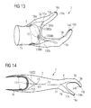
- FIG. 13 shows a hand prosthesis according to the invention as in FIG. 6 according to a second embodiment.
- the hand prosthesis 1 in FIG. 13 suitable for receiving a Mittelhandstumpfes.
- second contact surfaces 12 are arranged at a maximum distance from one another such that a center stump is in electrically conductive contact with the second contact surfaces 12 during the wearing of the prosthesis 1.
- the prosthesis in FIG. 12 has the prosthesis 1 in FIG. 13 In the region of the thumb or finger pressure surfaces 54a and 54b first contact surfaces 16a and 16b, which are each electrically conductively connected to an electrically conductive channel 13a and 13b.
- the channels 13a and 13b respectively extend along the finger end members 13a and 13b and along the second 52a, 52b and first finger members 51a and 51b to branching points 15a and 15b, respectively, in which the channels 13a and 13b respectively extend into two channels 13Ia, 13IIa and divide 13Ib and 13IIb.
- the channels 13Ia and 13IIa extend to the prosthesis socket 7e and are electrically conductively connected to one of the second contact surfaces 12.
- Another electrically conductive channel 13IIIa electrically connects the channels 13Ia and 13IIa to the third Contact surface 12, which is electrically connected to neither the channel 13Ia still with the channel 13IIa.
- the channels 13Ib and 13IIb also extend to the prosthesis shaft 7e and are also electrically connected to one of the second contact surfaces 12.
- Another electrically conductive channel 13IIIb electrically connects the channels 13Ib and 13IIb to the third contact surface 12, which is electrically connected neither to the channel 13Ib nor to the channel 13IIb.
- FIG. 14 shows a forearm prosthesis 1 according to the invention as in FIG. 7 according to a second embodiment.
- the prostheses in the FIGS. 8 and 9 has the prosthesis 1 in FIG. 14
- the channels 13a and 13b open into the electrically conductive channel 13, which is up to a branch point 15 in the region of the imaginary elbow joint ,
- the channel 13 divides into the electrically conductive channels 13I, 13II and 13III, which extend to the prosthesis shaft 7f.
- three second contact surfaces 12 are arranged approximately maximally spaced from one another.
- the second contact surfaces 12 are electrically conductively connected to one of the channels 13 I, 13 II and 13 III.
- the second contact surfaces 12 are further arranged on the prosthesis shaft 7 f such that they are in electrically conductive contact with an upper arm stump during the wearing of the prosthesis 1.
- an electrical contact during wearing of the prosthesis 1 between the first contact surfaces 16a and 16b and an upper arm stump via the channels 13a and 13b, 13 and 13I, 13II, 13III and the second contact surfaces 12, an electrical contact.
- FIG. 15 shows a prosthesis coating 100 according to the invention for a finger prosthesis according to a third embodiment.
- the prosthesis cover 100 is similar to a human finger 5.
- the interior of the prosthesis cover 100 extends along the first finger member 51, the second finger member 52 and to the central region of the finger end member 53, a cavity 17.
- the prosthesis cover facing in the imaginary hand Area of the first finger member 51, an opening 18 to the cavity 17, over which the prosthesis cover 100 can be pulled onto a finger prosthesis. While wearing the prosthesis cover, the cavity 17 receives the finger prosthesis in a form-fitting manner.
- An input unit for operating a capacitive touch-sensitive input device which has a contact surface 11 in the region of the finger pressure surface 54, is arranged on the finger end member 53 of the prosthesis coating 100.
- the contact surface 11 is tapered or semicircular on its side facing away from the finger 5.
Landscapes
- Health & Medical Sciences (AREA)
- Engineering & Computer Science (AREA)
- Transplantation (AREA)
- Orthopedic Medicine & Surgery (AREA)
- Heart & Thoracic Surgery (AREA)
- Biomedical Technology (AREA)
- Life Sciences & Earth Sciences (AREA)
- Animal Behavior & Ethology (AREA)
- General Health & Medical Sciences (AREA)
- Public Health (AREA)
- Veterinary Medicine (AREA)
- Vascular Medicine (AREA)
- Cardiology (AREA)
- Oral & Maxillofacial Surgery (AREA)
- Human Computer Interaction (AREA)
- Prostheses (AREA)
- Materials For Medical Uses (AREA)
- Position Input By Displaying (AREA)
Applications Claiming Priority (1)
| Application Number | Priority Date | Filing Date | Title |
|---|---|---|---|
| DE102012009699A DE102012009699A1 (de) | 2012-05-15 | 2012-05-15 | Prothese oder Prothesenüberzug |
Publications (3)
| Publication Number | Publication Date |
|---|---|
| EP2664302A2 true EP2664302A2 (fr) | 2013-11-20 |
| EP2664302A3 EP2664302A3 (fr) | 2014-12-17 |
| EP2664302B1 EP2664302B1 (fr) | 2018-07-11 |
Family
ID=48430529
Family Applications (1)
| Application Number | Title | Priority Date | Filing Date |
|---|---|---|---|
| EP13167766.8A Active EP2664302B1 (fr) | 2012-05-15 | 2013-05-15 | Prothèse ou revêtement de prothèse |
Country Status (2)
| Country | Link |
|---|---|
| EP (1) | EP2664302B1 (fr) |
| DE (1) | DE102012009699A1 (fr) |
Cited By (9)
| Publication number | Priority date | Publication date | Assignee | Title |
|---|---|---|---|---|
| WO2015149197A1 (fr) * | 2014-03-31 | 2015-10-08 | 北京大学 | Système de capteur de capacité sans contact pour prothèse intelligente |
| US10973660B2 (en) | 2017-12-15 | 2021-04-13 | Touch Bionics Limited | Powered prosthetic thumb |
| US20210196482A1 (en) * | 2017-10-13 | 2021-07-01 | The Board Of Regents Of The University Of Texas System | Digital extenders with haptic feedback |
| US11083600B2 (en) | 2014-02-25 | 2021-08-10 | Touch Bionics Limited | Prosthetic digit for use with touchscreen devices |
| WO2021239888A1 (fr) * | 2020-05-29 | 2021-12-02 | Otto Bock Healthcare Products Gmbh | Cosmèse, système constitué d'élément prothétique et de cosmèse, et partie de connexion |
| US11464654B2 (en) | 2014-02-04 | 2022-10-11 | Rehabilitation Institute Of Chicago | Modular and lightweight myoelectric prosthesis components and related methods |
| US11931270B2 (en) | 2019-11-15 | 2024-03-19 | Touch Bionics Limited | Prosthetic digit actuator |
| US12427040B2 (en) | 2019-04-10 | 2025-09-30 | Touch Bionics Limited | Prosthetic digit with articulating links |
| US12527672B2 (en) | 2019-09-18 | 2026-01-20 | Touch Bionics Limited | Prosthetic digits and actuators |
Families Citing this family (8)
| Publication number | Priority date | Publication date | Assignee | Title |
|---|---|---|---|---|
| GB201114264D0 (en) | 2011-08-18 | 2011-10-05 | Touch Emas Ltd | Improvements in or relating to prosthetics and orthotics |
| GB201302025D0 (en) | 2013-02-05 | 2013-03-20 | Touch Emas Ltd | Improvements in or relating to prosthetics |
| GB201408253D0 (en) | 2014-05-09 | 2014-06-25 | Touch Emas Ltd | Systems and methods for controlling a prosthetic hand |
| GB201417541D0 (en) | 2014-10-03 | 2014-11-19 | Touch Bionics Ltd | Wrist device for a prosthetic limb |
| US10369024B2 (en) | 2016-09-02 | 2019-08-06 | Touch Bionics Limited | Systems and methods for prosthetic wrist rotation |
| US11185426B2 (en) | 2016-09-02 | 2021-11-30 | Touch Bionics Limited | Systems and methods for prosthetic wrist rotation |
| RU205959U1 (ru) * | 2020-11-20 | 2021-08-12 | Общество с ограниченной ответственностью "МОТОРИКА" | Проводящий элемент для взаимодействия искусственного пальца с емкостным сенсорным экраном |
| RU2765089C1 (ru) * | 2020-11-20 | 2022-01-25 | Общество с ограниченной ответственностью "МОТОРИКА" | Протез кисти руки для взаимодействия с емкостным сенсорным экраном электронного устройства |
Family Cites Families (5)
| Publication number | Priority date | Publication date | Assignee | Title |
|---|---|---|---|---|
| US20090066658A1 (en) * | 2007-09-12 | 2009-03-12 | Earl Steven R | Glove attachment for touch sensitive data entry |
| US20100039392A1 (en) * | 2008-08-15 | 2010-02-18 | At&T Intellectual Property I, L.P. | Conductive fingernail |
| US8528117B2 (en) * | 2010-04-29 | 2013-09-10 | The Echo Design Group, Inc. | Gloves for touchscreen use |
| US20110278061A1 (en) * | 2010-05-13 | 2011-11-17 | Farnan Brian P | System to enable gloved hands to interact with electronic touchscreen devices |
| CA2754844C (fr) * | 2011-07-14 | 2018-06-12 | Charles Colin MacDuff | Prothese de doigt mecanique |
-
2012
- 2012-05-15 DE DE102012009699A patent/DE102012009699A1/de not_active Withdrawn
-
2013
- 2013-05-15 EP EP13167766.8A patent/EP2664302B1/fr active Active
Non-Patent Citations (1)
| Title |
|---|
| None |
Cited By (12)
| Publication number | Priority date | Publication date | Assignee | Title |
|---|---|---|---|---|
| US11464654B2 (en) | 2014-02-04 | 2022-10-11 | Rehabilitation Institute Of Chicago | Modular and lightweight myoelectric prosthesis components and related methods |
| US11083600B2 (en) | 2014-02-25 | 2021-08-10 | Touch Bionics Limited | Prosthetic digit for use with touchscreen devices |
| WO2015149197A1 (fr) * | 2014-03-31 | 2015-10-08 | 北京大学 | Système de capteur de capacité sans contact pour prothèse intelligente |
| US20210196482A1 (en) * | 2017-10-13 | 2021-07-01 | The Board Of Regents Of The University Of Texas System | Digital extenders with haptic feedback |
| US12290454B2 (en) * | 2017-10-13 | 2025-05-06 | Board Of Regents, The University Of Texas System | Digital extenders with haptic feedback |
| US10973660B2 (en) | 2017-12-15 | 2021-04-13 | Touch Bionics Limited | Powered prosthetic thumb |
| US11786381B2 (en) | 2017-12-15 | 2023-10-17 | Touch Bionics Limited | Powered prosthetic thumb |
| US12427040B2 (en) | 2019-04-10 | 2025-09-30 | Touch Bionics Limited | Prosthetic digit with articulating links |
| US12527672B2 (en) | 2019-09-18 | 2026-01-20 | Touch Bionics Limited | Prosthetic digits and actuators |
| US11931270B2 (en) | 2019-11-15 | 2024-03-19 | Touch Bionics Limited | Prosthetic digit actuator |
| WO2021239888A1 (fr) * | 2020-05-29 | 2021-12-02 | Otto Bock Healthcare Products Gmbh | Cosmèse, système constitué d'élément prothétique et de cosmèse, et partie de connexion |
| US20230201007A1 (en) * | 2020-05-29 | 2023-06-29 | Otto Bock Healthcare Products Gmbh | Cosmesis, system consisting of prosthetic component and cosmesis, and connection part |
Also Published As
| Publication number | Publication date |
|---|---|
| DE102012009699A1 (de) | 2013-11-21 |
| EP2664302B1 (fr) | 2018-07-11 |
| EP2664302A3 (fr) | 2014-12-17 |
Similar Documents
| Publication | Publication Date | Title |
|---|---|---|
| EP2664302B1 (fr) | Prothèse ou revêtement de prothèse | |
| DE102014019582A1 (de) | Haptik-Vorrichtungen und -Verfahren | |
| EP2688523B1 (fr) | Système de prothèse | |
| EP2525746A1 (fr) | Manchon à électrode intégrée | |
| Montagnani et al. | Independent long fingers are not essential for a grasping hand | |
| US20180116829A1 (en) | Myoelectric prosthesis and method | |
| EP2962726B1 (fr) | Systeme d'excitation de sensations fantomes | |
| DE102017119490B3 (de) | Prothesensystem und Verfahren zur Überprüfung der Funktionsfähigkeit eines Prothesensystems | |
| US20240390164A1 (en) | Biomedical finger assembly for use with capacitive panels and methods for manufacturing same | |
| DE102015006515A1 (de) | Kosmetischer Überzug für Prothesen | |
| Yang et al. | Experimental study of an EMG-controlled 5-DOF anthropomorphic prosthetic hand for motion restoration | |
| DE10305125B3 (de) | Neutralelektrode für die HF-Chirurgie | |
| Cheng et al. | Fascicle-specific targeting of longitudinal intrafascicular electrodes for motor and sensory restoration in upper-limb amputees | |
| CN105640677A (zh) | 一种用于假肢手感知反馈的电刺激感知反馈系统 | |
| DE102017126463A1 (de) | Orthopädietechnische Einrichtung | |
| DE102017005765A1 (de) | Fingerelement | |
| WO2006099886A1 (fr) | Ensemble de creation d'une articulation metatarsophalangienne | |
| DE102008036714B4 (de) | Verfahren zur Visualisierung mehrkanaliger Signale | |
| DE102007013660A1 (de) | Exoprothese | |
| DE102013111161A1 (de) | Handprothese | |
| EP3669380B1 (fr) | Gant de protection destiné à protéger contre les rayons pénétrants | |
| DE102015202179A1 (de) | Verfahren und Vorrichtung zur Bestimmung einer Handsteifigkeit | |
| EP4432986A1 (fr) | Protection pour une main prothétique et son procédé de fabrication | |
| DE202023107036U1 (de) | Bedienknopfvorrichtung für einen Touchscreen | |
| DE202015105668U1 (de) | Bandage für ein Gelenk des menschlichen Körpers und Pelottenelement |
Legal Events
| Date | Code | Title | Description |
|---|---|---|---|
| PUAI | Public reference made under article 153(3) epc to a published international application that has entered the european phase |
Free format text: ORIGINAL CODE: 0009012 |
|
| AK | Designated contracting states |
Kind code of ref document: A2 Designated state(s): AL AT BE BG CH CY CZ DE DK EE ES FI FR GB GR HR HU IE IS IT LI LT LU LV MC MK MT NL NO PL PT RO RS SE SI SK SM TR |
|
| AX | Request for extension of the european patent |
Extension state: BA ME |
|
| PUAL | Search report despatched |
Free format text: ORIGINAL CODE: 0009013 |
|
| AK | Designated contracting states |
Kind code of ref document: A3 Designated state(s): AL AT BE BG CH CY CZ DE DK EE ES FI FR GB GR HR HU IE IS IT LI LT LU LV MC MK MT NL NO PL PT RO RS SE SI SK SM TR |
|
| AX | Request for extension of the european patent |
Extension state: BA ME |
|
| RIC1 | Information provided on ipc code assigned before grant |
Ipc: A61F 2/58 20060101AFI20141107BHEP Ipc: A61F 2/70 20060101ALI20141107BHEP Ipc: A61F 2/50 20060101ALI20141107BHEP Ipc: A61F 4/00 20060101ALI20141107BHEP |
|
| 17P | Request for examination filed |
Effective date: 20150615 |
|
| RBV | Designated contracting states (corrected) |
Designated state(s): AL AT BE BG CH CY CZ DE DK EE ES FI FR GB GR HR HU IE IS IT LI LT LU LV MC MK MT NL NO PL PT RO RS SE SI SK SM TR |
|
| STAA | Information on the status of an ep patent application or granted ep patent |
Free format text: STATUS: EXAMINATION IS IN PROGRESS |
|
| 17Q | First examination report despatched |
Effective date: 20170207 |
|
| GRAP | Despatch of communication of intention to grant a patent |
Free format text: ORIGINAL CODE: EPIDOSNIGR1 |
|
| STAA | Information on the status of an ep patent application or granted ep patent |
Free format text: STATUS: GRANT OF PATENT IS INTENDED |
|
| INTG | Intention to grant announced |
Effective date: 20180105 |
|
| GRAS | Grant fee paid |
Free format text: ORIGINAL CODE: EPIDOSNIGR3 |
|
| GRAA | (expected) grant |
Free format text: ORIGINAL CODE: 0009210 |
|
| STAA | Information on the status of an ep patent application or granted ep patent |
Free format text: STATUS: THE PATENT HAS BEEN GRANTED |
|
| AK | Designated contracting states |
Kind code of ref document: B1 Designated state(s): AL AT BE BG CH CY CZ DE DK EE ES FI FR GB GR HR HU IE IS IT LI LT LU LV MC MK MT NL NO PL PT RO RS SE SI SK SM TR |
|
| REG | Reference to a national code |
Ref country code: GB Ref legal event code: FG4D Free format text: NOT ENGLISH |
|
| REG | Reference to a national code |
Ref country code: CH Ref legal event code: EP |
|
| REG | Reference to a national code |
Ref country code: AT Ref legal event code: REF Ref document number: 1016129 Country of ref document: AT Kind code of ref document: T Effective date: 20180715 |
|
| REG | Reference to a national code |
Ref country code: IE Ref legal event code: FG4D Free format text: LANGUAGE OF EP DOCUMENT: GERMAN |
|
| REG | Reference to a national code |
Ref country code: DE Ref legal event code: R096 Ref document number: 502013010571 Country of ref document: DE |
|
| REG | Reference to a national code |
Ref country code: NL Ref legal event code: MP Effective date: 20180711 |
|
| REG | Reference to a national code |
Ref country code: LT Ref legal event code: MG4D |
|
| PG25 | Lapsed in a contracting state [announced via postgrant information from national office to epo] |
Ref country code: NL Free format text: LAPSE BECAUSE OF FAILURE TO SUBMIT A TRANSLATION OF THE DESCRIPTION OR TO PAY THE FEE WITHIN THE PRESCRIBED TIME-LIMIT Effective date: 20180711 |
|
| PG25 | Lapsed in a contracting state [announced via postgrant information from national office to epo] |
Ref country code: PL Free format text: LAPSE BECAUSE OF FAILURE TO SUBMIT A TRANSLATION OF THE DESCRIPTION OR TO PAY THE FEE WITHIN THE PRESCRIBED TIME-LIMIT Effective date: 20180711 Ref country code: IS Free format text: LAPSE BECAUSE OF FAILURE TO SUBMIT A TRANSLATION OF THE DESCRIPTION OR TO PAY THE FEE WITHIN THE PRESCRIBED TIME-LIMIT Effective date: 20181111 Ref country code: RS Free format text: LAPSE BECAUSE OF FAILURE TO SUBMIT A TRANSLATION OF THE DESCRIPTION OR TO PAY THE FEE WITHIN THE PRESCRIBED TIME-LIMIT Effective date: 20180711 Ref country code: LT Free format text: LAPSE BECAUSE OF FAILURE TO SUBMIT A TRANSLATION OF THE DESCRIPTION OR TO PAY THE FEE WITHIN THE PRESCRIBED TIME-LIMIT Effective date: 20180711 Ref country code: BG Free format text: LAPSE BECAUSE OF FAILURE TO SUBMIT A TRANSLATION OF THE DESCRIPTION OR TO PAY THE FEE WITHIN THE PRESCRIBED TIME-LIMIT Effective date: 20181011 Ref country code: SE Free format text: LAPSE BECAUSE OF FAILURE TO SUBMIT A TRANSLATION OF THE DESCRIPTION OR TO PAY THE FEE WITHIN THE PRESCRIBED TIME-LIMIT Effective date: 20180711 Ref country code: FI Free format text: LAPSE BECAUSE OF FAILURE TO SUBMIT A TRANSLATION OF THE DESCRIPTION OR TO PAY THE FEE WITHIN THE PRESCRIBED TIME-LIMIT Effective date: 20180711 Ref country code: GR Free format text: LAPSE BECAUSE OF FAILURE TO SUBMIT A TRANSLATION OF THE DESCRIPTION OR TO PAY THE FEE WITHIN THE PRESCRIBED TIME-LIMIT Effective date: 20181012 Ref country code: NO Free format text: LAPSE BECAUSE OF FAILURE TO SUBMIT A TRANSLATION OF THE DESCRIPTION OR TO PAY THE FEE WITHIN THE PRESCRIBED TIME-LIMIT Effective date: 20181011 |
|
| PG25 | Lapsed in a contracting state [announced via postgrant information from national office to epo] |
Ref country code: ES Free format text: LAPSE BECAUSE OF FAILURE TO SUBMIT A TRANSLATION OF THE DESCRIPTION OR TO PAY THE FEE WITHIN THE PRESCRIBED TIME-LIMIT Effective date: 20180711 Ref country code: LV Free format text: LAPSE BECAUSE OF FAILURE TO SUBMIT A TRANSLATION OF THE DESCRIPTION OR TO PAY THE FEE WITHIN THE PRESCRIBED TIME-LIMIT Effective date: 20180711 Ref country code: HR Free format text: LAPSE BECAUSE OF FAILURE TO SUBMIT A TRANSLATION OF THE DESCRIPTION OR TO PAY THE FEE WITHIN THE PRESCRIBED TIME-LIMIT Effective date: 20180711 Ref country code: AL Free format text: LAPSE BECAUSE OF FAILURE TO SUBMIT A TRANSLATION OF THE DESCRIPTION OR TO PAY THE FEE WITHIN THE PRESCRIBED TIME-LIMIT Effective date: 20180711 |
|
| REG | Reference to a national code |
Ref country code: DE Ref legal event code: R097 Ref document number: 502013010571 Country of ref document: DE |
|
| PG25 | Lapsed in a contracting state [announced via postgrant information from national office to epo] |
Ref country code: EE Free format text: LAPSE BECAUSE OF FAILURE TO SUBMIT A TRANSLATION OF THE DESCRIPTION OR TO PAY THE FEE WITHIN THE PRESCRIBED TIME-LIMIT Effective date: 20180711 Ref country code: RO Free format text: LAPSE BECAUSE OF FAILURE TO SUBMIT A TRANSLATION OF THE DESCRIPTION OR TO PAY THE FEE WITHIN THE PRESCRIBED TIME-LIMIT Effective date: 20180711 Ref country code: IT Free format text: LAPSE BECAUSE OF FAILURE TO SUBMIT A TRANSLATION OF THE DESCRIPTION OR TO PAY THE FEE WITHIN THE PRESCRIBED TIME-LIMIT Effective date: 20180711 Ref country code: CZ Free format text: LAPSE BECAUSE OF FAILURE TO SUBMIT A TRANSLATION OF THE DESCRIPTION OR TO PAY THE FEE WITHIN THE PRESCRIBED TIME-LIMIT Effective date: 20180711 |
|
| PLBE | No opposition filed within time limit |
Free format text: ORIGINAL CODE: 0009261 |
|
| STAA | Information on the status of an ep patent application or granted ep patent |
Free format text: STATUS: NO OPPOSITION FILED WITHIN TIME LIMIT |
|
| PG25 | Lapsed in a contracting state [announced via postgrant information from national office to epo] |
Ref country code: SK Free format text: LAPSE BECAUSE OF FAILURE TO SUBMIT A TRANSLATION OF THE DESCRIPTION OR TO PAY THE FEE WITHIN THE PRESCRIBED TIME-LIMIT Effective date: 20180711 Ref country code: DK Free format text: LAPSE BECAUSE OF FAILURE TO SUBMIT A TRANSLATION OF THE DESCRIPTION OR TO PAY THE FEE WITHIN THE PRESCRIBED TIME-LIMIT Effective date: 20180711 Ref country code: SM Free format text: LAPSE BECAUSE OF FAILURE TO SUBMIT A TRANSLATION OF THE DESCRIPTION OR TO PAY THE FEE WITHIN THE PRESCRIBED TIME-LIMIT Effective date: 20180711 |
|
| 26N | No opposition filed |
Effective date: 20190412 |
|
| PG25 | Lapsed in a contracting state [announced via postgrant information from national office to epo] |
Ref country code: SI Free format text: LAPSE BECAUSE OF FAILURE TO SUBMIT A TRANSLATION OF THE DESCRIPTION OR TO PAY THE FEE WITHIN THE PRESCRIBED TIME-LIMIT Effective date: 20180711 |
|
| GBPC | Gb: european patent ceased through non-payment of renewal fee |
Effective date: 20190515 |
|
| PG25 | Lapsed in a contracting state [announced via postgrant information from national office to epo] |
Ref country code: MC Free format text: LAPSE BECAUSE OF FAILURE TO SUBMIT A TRANSLATION OF THE DESCRIPTION OR TO PAY THE FEE WITHIN THE PRESCRIBED TIME-LIMIT Effective date: 20180711 |
|
| REG | Reference to a national code |
Ref country code: BE Ref legal event code: MM Effective date: 20190531 |
|
| PG25 | Lapsed in a contracting state [announced via postgrant information from national office to epo] |
Ref country code: LU Free format text: LAPSE BECAUSE OF NON-PAYMENT OF DUE FEES Effective date: 20190515 |
|
| PG25 | Lapsed in a contracting state [announced via postgrant information from national office to epo] |
Ref country code: TR Free format text: LAPSE BECAUSE OF FAILURE TO SUBMIT A TRANSLATION OF THE DESCRIPTION OR TO PAY THE FEE WITHIN THE PRESCRIBED TIME-LIMIT Effective date: 20180711 |
|
| PG25 | Lapsed in a contracting state [announced via postgrant information from national office to epo] |
Ref country code: IE Free format text: LAPSE BECAUSE OF NON-PAYMENT OF DUE FEES Effective date: 20190515 Ref country code: GB Free format text: LAPSE BECAUSE OF NON-PAYMENT OF DUE FEES Effective date: 20190515 |
|
| PG25 | Lapsed in a contracting state [announced via postgrant information from national office to epo] |
Ref country code: BE Free format text: LAPSE BECAUSE OF NON-PAYMENT OF DUE FEES Effective date: 20190531 |
|
| PG25 | Lapsed in a contracting state [announced via postgrant information from national office to epo] |
Ref country code: PT Free format text: LAPSE BECAUSE OF FAILURE TO SUBMIT A TRANSLATION OF THE DESCRIPTION OR TO PAY THE FEE WITHIN THE PRESCRIBED TIME-LIMIT Effective date: 20181111 |
|
| PG25 | Lapsed in a contracting state [announced via postgrant information from national office to epo] |
Ref country code: CY Free format text: LAPSE BECAUSE OF FAILURE TO SUBMIT A TRANSLATION OF THE DESCRIPTION OR TO PAY THE FEE WITHIN THE PRESCRIBED TIME-LIMIT Effective date: 20180711 |
|
| PG25 | Lapsed in a contracting state [announced via postgrant information from national office to epo] |
Ref country code: HU Free format text: LAPSE BECAUSE OF FAILURE TO SUBMIT A TRANSLATION OF THE DESCRIPTION OR TO PAY THE FEE WITHIN THE PRESCRIBED TIME-LIMIT; INVALID AB INITIO Effective date: 20130515 Ref country code: MT Free format text: LAPSE BECAUSE OF FAILURE TO SUBMIT A TRANSLATION OF THE DESCRIPTION OR TO PAY THE FEE WITHIN THE PRESCRIBED TIME-LIMIT Effective date: 20180711 |
|
| PGFP | Annual fee paid to national office [announced via postgrant information from national office to epo] |
Ref country code: AT Payment date: 20210518 Year of fee payment: 9 |
|
| PG25 | Lapsed in a contracting state [announced via postgrant information from national office to epo] |
Ref country code: MK Free format text: LAPSE BECAUSE OF FAILURE TO SUBMIT A TRANSLATION OF THE DESCRIPTION OR TO PAY THE FEE WITHIN THE PRESCRIBED TIME-LIMIT Effective date: 20180711 |
|
| PGFP | Annual fee paid to national office [announced via postgrant information from national office to epo] |
Ref country code: CH Payment date: 20220523 Year of fee payment: 10 |
|
| REG | Reference to a national code |
Ref country code: AT Ref legal event code: MM01 Ref document number: 1016129 Country of ref document: AT Kind code of ref document: T Effective date: 20220515 |
|
| PG25 | Lapsed in a contracting state [announced via postgrant information from national office to epo] |
Ref country code: AT Free format text: LAPSE BECAUSE OF NON-PAYMENT OF DUE FEES Effective date: 20220515 |
|
| P01 | Opt-out of the competence of the unified patent court (upc) registered |
Effective date: 20230526 |
|
| REG | Reference to a national code |
Ref country code: CH Ref legal event code: PL |
|
| PG25 | Lapsed in a contracting state [announced via postgrant information from national office to epo] |
Ref country code: LI Free format text: LAPSE BECAUSE OF NON-PAYMENT OF DUE FEES Effective date: 20230531 Ref country code: CH Free format text: LAPSE BECAUSE OF NON-PAYMENT OF DUE FEES Effective date: 20230531 |
|
| PGFP | Annual fee paid to national office [announced via postgrant information from national office to epo] |
Ref country code: DE Payment date: 20250519 Year of fee payment: 13 |
|
| PGFP | Annual fee paid to national office [announced via postgrant information from national office to epo] |
Ref country code: FR Payment date: 20250521 Year of fee payment: 13 |