EP2664535A1 - Dispositif de contrôle d'un moteur - Google Patents
Dispositif de contrôle d'un moteur Download PDFInfo
- Publication number
- EP2664535A1 EP2664535A1 EP13002506.7A EP13002506A EP2664535A1 EP 2664535 A1 EP2664535 A1 EP 2664535A1 EP 13002506 A EP13002506 A EP 13002506A EP 2664535 A1 EP2664535 A1 EP 2664535A1
- Authority
- EP
- European Patent Office
- Prior art keywords
- ratio
- torque
- gear ratio
- gear
- assist
- Prior art date
- Legal status (The legal status is an assumption and is not a legal conclusion. Google has not performed a legal analysis and makes no representation as to the accuracy of the status listed.)
- Granted
Links
- 230000000694 effects Effects 0.000 claims description 15
- 230000002441 reversible effect Effects 0.000 claims description 10
- 230000000737 periodic effect Effects 0.000 claims description 4
- 230000006870 function Effects 0.000 description 40
- 238000004364 calculation method Methods 0.000 description 19
- 230000005540 biological transmission Effects 0.000 description 18
- 230000004913 activation Effects 0.000 description 16
- 230000001172 regenerating effect Effects 0.000 description 16
- 238000010586 diagram Methods 0.000 description 12
- 230000007423 decrease Effects 0.000 description 10
- 230000008929 regeneration Effects 0.000 description 10
- 238000011069 regeneration method Methods 0.000 description 10
- 238000009499 grossing Methods 0.000 description 8
- 230000009194 climbing Effects 0.000 description 7
- 238000000034 method Methods 0.000 description 7
- 238000009789 rate limiting process Methods 0.000 description 5
- 235000014676 Phragmites communis Nutrition 0.000 description 4
- 230000008901 benefit Effects 0.000 description 4
- 230000033228 biological regulation Effects 0.000 description 4
- 230000008569 process Effects 0.000 description 4
- 230000008859 change Effects 0.000 description 3
- 238000006243 chemical reaction Methods 0.000 description 3
- 230000004048 modification Effects 0.000 description 3
- 238000012986 modification Methods 0.000 description 3
- HBBGRARXTFLTSG-UHFFFAOYSA-N Lithium ion Chemical compound [Li+] HBBGRARXTFLTSG-UHFFFAOYSA-N 0.000 description 2
- 241000220317 Rosa Species 0.000 description 2
- 230000000295 complement effect Effects 0.000 description 2
- 238000007796 conventional method Methods 0.000 description 2
- 238000001514 detection method Methods 0.000 description 2
- 229910001416 lithium ion Inorganic materials 0.000 description 2
- 230000001052 transient effect Effects 0.000 description 2
- 230000001133 acceleration Effects 0.000 description 1
- 230000005669 field effect Effects 0.000 description 1
- 230000010354 integration Effects 0.000 description 1
- 229910052987 metal hydride Inorganic materials 0.000 description 1
- 230000003287 optical effect Effects 0.000 description 1
- 229920000642 polymer Polymers 0.000 description 1
- 239000004065 semiconductor Substances 0.000 description 1
Images


Classifications
-
- B—PERFORMING OPERATIONS; TRANSPORTING
- B62—LAND VEHICLES FOR TRAVELLING OTHERWISE THAN ON RAILS
- B62M—RIDER PROPULSION OF WHEELED VEHICLES OR SLEDGES; POWERED PROPULSION OF SLEDGES OR SINGLE-TRACK CYCLES; TRANSMISSIONS SPECIALLY ADAPTED FOR SUCH VEHICLES
- B62M6/00—Rider propulsion of wheeled vehicles with additional source of power, e.g. combustion engine or electric motor
- B62M6/40—Rider propelled cycles with auxiliary electric motor
- B62M6/45—Control or actuating devices therefor
-
- B—PERFORMING OPERATIONS; TRANSPORTING
- B60—VEHICLES IN GENERAL
- B60L—PROPULSION OF ELECTRICALLY-PROPELLED VEHICLES; SUPPLYING ELECTRIC POWER FOR AUXILIARY EQUIPMENT OF ELECTRICALLY-PROPELLED VEHICLES; ELECTRODYNAMIC BRAKE SYSTEMS FOR VEHICLES IN GENERAL; MAGNETIC SUSPENSION OR LEVITATION FOR VEHICLES; MONITORING OPERATING VARIABLES OF ELECTRICALLY-PROPELLED VEHICLES; ELECTRIC SAFETY DEVICES FOR ELECTRICALLY-PROPELLED VEHICLES
- B60L15/00—Methods, circuits, or devices for controlling the traction-motor speed of electrically-propelled vehicles
- B60L15/20—Methods, circuits, or devices for controlling the traction-motor speed of electrically-propelled vehicles for control of the vehicle or its driving motor to achieve a desired performance, e.g. speed, torque, programmed variation of speed
- B60L15/2054—Methods, circuits, or devices for controlling the traction-motor speed of electrically-propelled vehicles for control of the vehicle or its driving motor to achieve a desired performance, e.g. speed, torque, programmed variation of speed by controlling transmissions or clutches
-
- B—PERFORMING OPERATIONS; TRANSPORTING
- B60—VEHICLES IN GENERAL
- B60L—PROPULSION OF ELECTRICALLY-PROPELLED VEHICLES; SUPPLYING ELECTRIC POWER FOR AUXILIARY EQUIPMENT OF ELECTRICALLY-PROPELLED VEHICLES; ELECTRODYNAMIC BRAKE SYSTEMS FOR VEHICLES IN GENERAL; MAGNETIC SUSPENSION OR LEVITATION FOR VEHICLES; MONITORING OPERATING VARIABLES OF ELECTRICALLY-PROPELLED VEHICLES; ELECTRIC SAFETY DEVICES FOR ELECTRICALLY-PROPELLED VEHICLES
- B60L50/00—Electric propulsion with power supplied within the vehicle
- B60L50/20—Electric propulsion with power supplied within the vehicle using propulsion power generated by humans or animals
-
- B—PERFORMING OPERATIONS; TRANSPORTING
- B60—VEHICLES IN GENERAL
- B60L—PROPULSION OF ELECTRICALLY-PROPELLED VEHICLES; SUPPLYING ELECTRIC POWER FOR AUXILIARY EQUIPMENT OF ELECTRICALLY-PROPELLED VEHICLES; ELECTRODYNAMIC BRAKE SYSTEMS FOR VEHICLES IN GENERAL; MAGNETIC SUSPENSION OR LEVITATION FOR VEHICLES; MONITORING OPERATING VARIABLES OF ELECTRICALLY-PROPELLED VEHICLES; ELECTRIC SAFETY DEVICES FOR ELECTRICALLY-PROPELLED VEHICLES
- B60L2200/00—Type of vehicles
- B60L2200/12—Bikes
-
- Y—GENERAL TAGGING OF NEW TECHNOLOGICAL DEVELOPMENTS; GENERAL TAGGING OF CROSS-SECTIONAL TECHNOLOGIES SPANNING OVER SEVERAL SECTIONS OF THE IPC; TECHNICAL SUBJECTS COVERED BY FORMER USPC CROSS-REFERENCE ART COLLECTIONS [XRACs] AND DIGESTS
- Y02—TECHNOLOGIES OR APPLICATIONS FOR MITIGATION OR ADAPTATION AGAINST CLIMATE CHANGE
- Y02T—CLIMATE CHANGE MITIGATION TECHNOLOGIES RELATED TO TRANSPORTATION
- Y02T10/00—Road transport of goods or passengers
- Y02T10/60—Other road transportation technologies with climate change mitigation effect
- Y02T10/64—Electric machine technologies in electromobility
-
- Y—GENERAL TAGGING OF NEW TECHNOLOGICAL DEVELOPMENTS; GENERAL TAGGING OF CROSS-SECTIONAL TECHNOLOGIES SPANNING OVER SEVERAL SECTIONS OF THE IPC; TECHNICAL SUBJECTS COVERED BY FORMER USPC CROSS-REFERENCE ART COLLECTIONS [XRACs] AND DIGESTS
- Y02—TECHNOLOGIES OR APPLICATIONS FOR MITIGATION OR ADAPTATION AGAINST CLIMATE CHANGE
- Y02T—CLIMATE CHANGE MITIGATION TECHNOLOGIES RELATED TO TRANSPORTATION
- Y02T10/00—Road transport of goods or passengers
- Y02T10/60—Other road transportation technologies with climate change mitigation effect
- Y02T10/72—Electric energy management in electromobility
Definitions
- the present invention relates to a motor drive control device for a so-called electric power-assisted vehicle such as a bicycle with a motor.
- Power transmission systems of an electric power assist bicycle include several variations shown in FIGs. 1 to 5 .
- a one-way clutch is installed on the rear wheel gear (hereinafter referred to as an R gear).
- a decelerator may or may not be provided depending on the torque and speed characteristics of the motor.
- FIG. 1 shows a first configuration in which a transmission system that transmits torque from a motor to a rear wheel and a transmission system that transmits torque from a pedal to the rear wheel share a gear shifter.
- both the pedal and the motor drive the same front gear (hereinafter referred to as the F gear), and the front wheel is not driven.
- FIG. 2 shows a second configuration in which a transmission system that transmits torque from a motor to a rear wheel and a transmission system that transmits torque from a pedal to the rear wheel share a gear shifter.
- the middle gear of the chain driven by the pedal is also driven by the motor.
- the front wheel is not driven in this configuration either.
- FIG. 3 shows a third configuration in which a transmission system that transmits torque from a motor to a rear wheel and a transmission system that transmits torque from a pedal to the rear wheel share a gear shifter.
- the rear wheel is driven by pedal and motor via two chains, respectively.
- the front wheel is not driven in this configuration either.
- FIG. 4 shows a first configuration in which a gear shifter is installed only in the drive route from the pedal.
- a rear wheel motor drives a real wheel hub (corresponding to the black circle in FIG. 4 ) to the rear of the gear shifter.
- driving is conducted with the rear wheel motor further towards the rear wheel than a one way clutch installed in the R gear, and thus, it is possible to use an electromagnetic brake.
- the front wheel is not driven in this configuration either.
- FIG. 5 shows a second configuration in which a gear shifter is installed only in the drive route from the pedal.
- the motor drives the front wheel. Because there is no one way clutch on the front wheel side, it is possible to use an electromagnetic brake.
- pedal input torque and assist motor torque from the motor both drive the rear wheel through the gear shifter, and thus, even if the gear shift position, or in other words the gear ratio, changes, the ratio of the torque applied by the pedal to drive the drive wheel (in this case the rear wheel) to the torque applied by the motor to drive the drive wheel, or in other words the assist ratio, does not change.
- the pedal input torque and the assist motor torque work through the R gear, the torque is applied through the one way clutch provided in the R gear.
- torque from the electromagnetic brake which is in the opposite direction, is not transmitted.
- the gear shifter is a three-speed gear shifter, and that the H (high speed) position of the gear shifter has a gear ratio of 4/3, the M (mid speed) position has a gear ratio of 1, and the L (low speed) position has a gear ratio of 3/4.
- the assist ratio is 1 / (3/4) or 4/3 that of when the M position is used.
- the assist ratio is 1 / (4/3) or 3/4 that of when the M position is used.
- the assist ratio decreases, and when the H position is used, typically during low load situations, the assist ratio is increased.
- the maximum assist ratio be a function of the speed of the vehicle.
- the average assist ratio the average assist ratio during a ripple fluctuation cycle if the assist ratio has such a ripple fluctuation cycle
- the maximum average assist ratio needs to follow a curve in which the assist ratio is maintained at 2 up to 10km/h, and between 10km/h and 24km/h inclusive, the assist ratio decreases in a linear manner such that the maximum average assist ratio at 24km/h is 0.
- whether the system meets the requirements of the regulations is determined based on the H position in which the assist ratio is greater, and thus, in the M position or the L position, it is not possible to maximize the assist ratio to the fullest within the legal framework.
- the average assist ratio in the M position is 3/2
- the average assist ratio in the H position is 2
- the average assist ratio in the L position is 9/8.
- the average assist ratio in the M position is 1, then the average assist ratio in the H position is 4/3 and the average assist ratio in the L position is 3/4.
- a technique has been disclosed in which the ratio of the electric motor to human driving power is small at a high speed setting and large at a low speed setting in order to encourage the rider to shift to a gear appropriate to the running speed, with the view that there is a problem that the motor efficiency is low when a vehicle with a power transmission system of a configuration similar to that shown in FIG. 1 runs at low speeds even in high gear.
- the assist ratio by the motor becomes small, thus increasing the amount of human driving power required.
- the rider is encouraged to shift gears by the discomfort of having to provide more driving power, and when the gear is actually shifted, a large assist ratio is provided in low gear.
- the power transmission system of the configuration shown in FIG. 1 is used, and use of such a ratio setting for the power transmission system of the configurations shown in FIGs. 4 and 5 has not been considered.
- Patent Document 1 Japanese Patent No. 3190491
- an object of the present invention is to appropriately control the assist ratio of an electric power-assisted vehicle that has a gear shifter and a motor and in which the ratio of the number of rotations in the motor to the number of rotations of the pedal changes depending on changes in the gear ratio.
- a motor drive control device for an electric power-assisted vehicle having a gear shifter and a motor in which a first ratio of a number of drive rotations in the motor to a number of rotations of a pedal changes according to changes in a gear ratio of the gear shifter, the device including: a gear ratio obtaining part that obtains a gear ratio of the gear shifter; and a calculating part that calculates an assist torque, which is a target value for a drive torque of the motor, from a pedal input torque, based on the gear ratio obtained from the gear ratio obtaining part.
- the first ratio sometimes changes in the direction opposite to the control direction, and thus, when calculating the assist torque, characteristics of the electric power-assisted vehicle are taken into consideration.
- the calculating part may calculate the assist torque by factoring in an effect of the gear shifter on the drive torque of the motor driven based on the assist torque, in a reverse direction based on the gear ratio.
- the above-mentioned calculating part may set a second ratio of an average assist torque, which represents a one cycle average of the assist torque, to an average pedal input torque, which represents a one cycle average of the pedal input torque, so as to be lower when the gear ratio is set higher compared to when the gear ratio is set lower, and then calculate the assist torque based on the second ratio.
- the above-mentioned calculating part may set the second ratio so as to be proportional to a value resulting from raising the gear ratio by an exponent of -1 or less. By doing so, it is possible to provide an assist appropriate to a situation in which more assist is desired.
- the above-mentioned calculating part may limit the second ratio by a separately set upper limit value for the second ratio. This is in order to comply with regulations, legal or otherwise.
- the calculating part may set the second ratio so as to be proportional to a value resulting from raising the gear ratio by an exponent of -1 or less, and limit the second ratio by a product of a third ratio that is inversely proportional to the gear ratio and a limiting value based on the vehicle speed (in other words, the upper limit). By doing so, no matter what the gear ratio is, it is possible to calculate the assist torque using the second ratio up to the upper limit.
- the above-mentioned calculating part may change the amount of periodic fluctuation in the total drive power constituted of the wheel drive power by a pedal input torque, which includes periodic torque variation, and a wheel drive power by the assist torque, based on the gear ratio.
- An appropriate assist can be provided based on the load calculated by the gear ratio, for example.
- the calculating part may determine, based on the gear ratio, a coefficient by which to multiply a difference between a smoothed pedal input torque in which the pedal input torque is smoothed, and the pedal input torque, and calculate the assist torque by adding a product of the difference and the coefficient, to a product of the smoothed pedal input torque and the second ratio.
- the assist torque by adding a product of the difference and the coefficient, to a product of the smoothed pedal input torque and the second ratio.
- the above-mentioned coefficient may be set so as to be smaller when the gear ratio is set higher, compared to when the gear ratio is set lower. By doing so, in a situation in which assist is desired such as climbing hills, a coefficient can be set so as to correspond to the gear ratio.
- the upper limit value may be set based on a gear ratio at the highest speed, or the gear ratio when calculating a third ratio may be set based on a gear ratio at the highest speed. By doing so, it is possible to reliably fulfill legal requirements and the like.
- the above-mentioned calculating part may calculate the assist torque with a prescribed gear ratio at mid speed or a speed lower than mid speed in a situation in which the vehicle is at a standstill or the vehicle speed is lower than a prescribed value, and the pedal input torque is 0 or has started to rise from a small value. This is because in such a situation, a relatively large amount of assist is desired.
- the above-mentioned calculating part may use the gear ratio obtained immediately prior to that state. If the vehicle is running, for example, this allows assist to be provided without any unnatural feeling on the part of the rider.
- a motor drive control device for an electric power-assisted vehicle having a gear shifter and a motor in which a first ratio of a number of drive rotations in the motor to a number of rotations of a pedal changes according to changes in a gear ratio of the gear shifter, the device including: a controller that assumes a gear ratio lower than mid speed when conditions including that a prescribed amount of time has not passed since a pedal input torque has started increasing from 0 or a small value are satisfied, and assumes a gear ratio equal to or greater than mid speed when the conditions are no longer satisfied; and a calculating part that calculates an assist torque, which is a target value for a drive torque of the motor from the pedal input torque, based on the assumed gear ratio.
- the first ratio sometimes changes in the direction opposite to the control direction, and thus, when calculating the assist torque, characteristics of such a bicycle are taken into consideration when conducting control.
- the controller may output a correction coefficient, which is set factoring in an effect of the gear shifter on a drive torque of the motor driven based on the assist torque, in a reverse direction to the set gear ratio, and the calculating part may correct, based on the correction coefficient, a second ratio of an average assist torque, which represents a one cycle average of the assist torque, to an average pedal input torque, which represents a one cycle average of the pedal input torque.
- the above-mentioned calculating part may set a second ratio of an average assist torque, which represents a one cycle average of the assist torque, to an average pedal input torque, which represents a one cycle average of the pedal input torque, so as to be lower when the gear ratio is set higher compared to when the gear ratio is set lower, and calculate the assist torque based on the second ratio. By doing so, it is possible to calculate the assist torque such that more assist is given in a situation in which more assist is desired, such as when in low gear.
- the above-mentioned conditions sometimes further include a condition that a vehicle speed is less than a prescribed value. This is because the assist is desired even in such a case.
- the calculating part may limit the second ratio of an average assist torque, which represents a one cycle average of the assist torque, to an average pedal input torque, which represents a one cycle average of the pedal input torque, by an upper limit value set based on the highest speed gear ratio. This is because the gear ratio is an assumed gear ratio, and a limit needs to be set on the second ratio from a safety perspective.
- Such a process can be accomplished by writing a program to be executed by a microprocessor, and this program is stored in a storage medium or a storage device that is readable by a computer such as a floppy disk, an optical disc such as a CD-ROM, a magneto-optical disc, a semiconductor memory (such as ROM), a hard drive, or the like. Data to be processed is temporarily stored in a storage device such as a RAM (random access memory).
- the motor drive of a bicycle that has a gear shifter and a motor and in which the ratio of the pedal input torque to the motor drive torque changes based on changes in gear ratio in the gear shifter can be appropriately controlled.
- FIG. 8 is an external view that shows an example of a bicycle with a motor according to the present embodiment.
- This bicycle 1 with a motor has a power transmission system of a configuration shown in FIG. 5 , for example, and is a general rear wheel drive in which a crankshaft and a rear wheel are connected via chain.
- the bicycle 1 with a motor is an electric power-assisted vehicle that has a gear shifter and a motor and in which the ratio of the pedal input torque to the drive torque from the motor changes depending on changes in gear ratio in the gear shifter.
- the bicycle 1 is an electric power-assisted vehicle that has a gear shifter and a motor and in which a ratio of the motor drive rotations to the pedal drive rotations changes based on changes in the gear ratio in the gear shifter.
- the bicycle 1 with a motor has a motor drive device.
- the motor drive device has a secondary battery 101, a motor drive controller 102, a torque sensor 103, a brake sensor 104, a motor 105, a control panel 106, and a pedal rotation sensor 108.
- the secondary battery 101 is a lithium ion secondary battery in which the maximum supply voltage (voltage when fully charged) is 24V, for example, but the secondary battery 101 may be another type of battery such as a lithium ion polymer secondary battery or a nickel-metal hydride rechargeable battery.
- the torque sensor 103 is provided in a wheel installed on the crankshaft, detects force on the pedal by a rider, and outputs the result thereof to the motor drive controller 102.
- the pedal rotation sensor 108 is provided in a wheel installed on the crankshaft as in the torque sensor 103, and outputs a signal based on the rotations to the motor drive controller 102.
- the brake sensor 104 is constituted of a magnet and a known reed switch.
- the magnet is fixed to a brake wire connected to a brake lever in a case in which the brake lever is fixed and through which the brake wire passes.
- the brake lever is designed so as to switch the reed switch on when gripped by a hand.
- the reed switch is fixed inside the case. A conduction signal from the reed switch is transmitted to the motor drive controller 102.
- the motor 105 is a known three phase brushless motor, for example, and is installed on a front wheel of the bicycle 1 with a motor, for example.
- the motor 105 rotates the front wheel and a rotor is connected to the front wheel so as to rotate when the front wheel rotates.
- the motor 105 is provided with a rotation sensor such as a Hall element and outputs rotation information from the rotor (in other words a Hall signal) to the motor drive controller 102.
- the control panel 106 receives command input from the user on whether or not to provide assist, for example, and outputs the command input to the motor drive controller 102.
- the control panel 106 receives settings input on the assist ratio (the assist ratio at the M position; also referred to as a desired assist ratio) from the user and outputs the settings input to the motor drive controller 102.
- a signal representing the gear ratio is also outputted to the motor drive controller 102 from the gear shifter or the like.
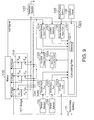
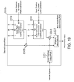
- the motor drive controller 102 has a controller 1020 and an FET (field effect transistor) bridge 1030.
- the FET bridge 1030 includes a high side FET (S uh ) and a low side FET (S ul ) that conduct U-phase switching for the motor 105, a high side FET (S vh ) and a low side FET (S vl ) that conduct V-phase switching for the motor 105, and a high side FET (S wh ) and a low side FET (S wl ) that conduct W-phase switching for the motor 105.
- the FET bridge 1030 constitutes a portion of the complementary switching amp.
- the controller 1020 has a calculating part 1021, a pedal rotation input part 1022, a current detector 1023, a vehicle speed input part 1024, a variable delay circuit 1025, a motor drive timing generator 1026, a torque input part 1027, a brake input part 1028, and an AD input part 1029.
- the calculating part 1021 conducts calculation to be mentioned below based on input from the control panel 106 (on/off and operating mode (such as the assist ratio), for example), input from the pedal rotation input part 1022, input from the current detector 1023, input from the vehicle speed input part 1024, input from the torque input part 1027, input from the brake input part 1028, and input from the AD input part 1029.
- the calculating part 1021 then outputs the calculation to the motor drive timing generator 1026 and the variable delay circuit 1025.
- the calculating part 1021 has a memory 10211, and the memory 10211 stores various types of data used for calculation, data during calculation, and the like.
- the calculating part 1021 is sometimes executed due to a program being executed by a processor, and in this case, the program is sometimes stored in the memory 10211.
- the pedal rotation input part 1022 digitizes input from the pedal rotation sensor 108 and outputs it to the calculating part 1021.
- the current detector 1023 digitizes a voltage value corresponding to a current using a detection resistor 107 that detects a current flowing to the FETs in the FET bridge 1030 and outputs the voltage value to the calculating part 1021.
- the vehicle speed input part 1024 calculates the current speed of the vehicle and the rotational cycle of the rear wheel from a Hall signal outputted from the motor 105, and outputs these data to the calculating part 1021.
- the torque input part 1027 digitizes a signal from the torque sensor 103 corresponding to a force applied to the pedal and outputs the signal to the calculating part 1021.
- the brake input part 1028 digitizes a signal from the brake sensor 104 corresponding to the brake force and outputs the signal to the calculating part 1021.
- the AD (analog-digital) input part 1029 digitizes output voltage from the secondary battery 101 and outputs it to the calculating part 1021.
- the memory 10211 is sometimes provided separately from the calculating part 1021.
- the calculating part 1021 outputs an advance angle value as the calculation result to the variable delay circuit 1025.
- the variable delay circuit 1025 adjusts the phase of the Hall signal based on the advance angle value received from the calculating part 1021 and outputs it to the motor drive timing generator 1026.
- the calculating part 1021 outputs a PWM (pulse width modulation) code, which corresponds to the duty cycle of the PWM, for example, as the calculation result to the motor drive timing generator 1026.
- the motor drive timing generator 1026 generates a switching signal to each FET included in the FET bridge 1030 based on the Hall signal after adjustment from the variable delay circuit 1025 and the PWM code from the calculating part 1021, and outputs the switching signal.
- FIGs. 10A to 10L show basic operations for driving the motor based on the configuration shown in FIG. 9 .
- FIG. 10A shows a U-phase Hall signal HU outputted from the motor 105
- FIG. 10B shows a V-phase Hall signal HV outputted from the motor 105
- FIG. 10C shows a W-phase Hall signal HW outputted from the motor 105.
- the Hall signal represents the rotational phase of the motor. Although the rotational phase is not obtained as a continuous value here, other sensors and the like may obtain a continuous value therefor.
- the Hall element of the motor 105 is provided so as to output the Hall signal at a somewhat advanced phase as shown in FIG.
- a U-phase Hall signal HU_In after adjustment as shown in FIG. 10D is outputted from the variable delay circuit 1025 to the motor drive timing generator 1026
- a V-phase Hall signal HV_In after adjustment as shown in FIG. 10E is outputted from the variable delay circuit 1025 to the motor drive timing generator 1026
- a W-phase Hall signal HW_In after adjustment as shown in FIG. 10F is outputted from the variable delay circuit 1025 to the motor drive timing generator 1026.
- One period of the Hall signal has 360° of electrical angle, which is divided into six phases.
- back electromotive force voltages include a Motor_U back electromotive force that is generated in a U-phase terminal, a Motor_V back electromotive force that is generated in a V-phase terminal, and a Motor_W back electromotive force that is generated in a W-phase terminal.
- a switching signal such as that shown in FIGs. 10J to 10L is outputted to a gate of each FET of the FET bridge 1030.
- 10J represents a U-phase high side FET (S uh ) gate signal
- U_LS represents a U-phase low side FET (S ul ) gate signal
- PWM and "/PWM” represent an on/off period in the duty cycle corresponding to the PWM code, which is the calculation result of the calculating part 1021, and because it is complementary, if PWM is on then /PWM is off, and if PWM is off, then /PWM is on.
- the low side FET (S ul ) stays on throughout the ON period.
- V_HS of FIG. 10K represents a V-phase high side FET (S vh ) gate signal
- V_LS represents a V-phase low side FET (S vl ) gate signal.
- W_HS in FIG. 10L represents a W-phase high side FET (S wh ) gate signal
- W_LS represents a W-phase low side FET (S wl ) gate signal.
- the reference characters are the same as those of FIG. 10J .
- the U-phase FETs (S uh and S ul ) conduct PWM switching at phases 1 and 2, and the U-phase low side FET (S ul ) is turned on in phases 4 and 5.
- the V-phase FETs (S vh and S vl ) conduct PWM switching at phases 3 and 4, and the V-phase low side FET (S vl ) is turned on in phases 6 and 1.
- the W-phase FETs (S wh and S wl ) conduct PWM switching in phases 5 and 6 and the W-phase low side FET (S wl ) is turned on in phases 2 and 3.
- the motor 105 can be driven with a desired torque.
- the calculating part 1021 has a regenerative brake target torque calculating part 1201, a regeneration activation part 1202, a drive torque target calculating part 1203, an assist activation part 1204, an adder 1206, a first duty cycle converter 1211, a torque slew rate limiter 1212, a second duty cycle converter 1213, a speed slew rate limiter 1215, an adder 1216, and a PWM code generator 1217.
- the vehicle speed value from the vehicle speed input part 1024 and the pedal torque value from the torque input part 1027 is inputted into the drive torque target calculating part 1203 and an assist torque value is calculated. Also, the pedal rotation period from the pedal rotation input part 1022 is also inputted into the drive torque target calculating part 1203 and is used when calculating the assist torque value. The calculations performed by the drive torque target calculating part 1203 will be described in detail below.
- the regenerative brake target torque calculating part 1201 calculates a regenerative brake target torque value according to a curve set in advance, for example, based on the vehicle speed value from the vehicle speed input part 1024.
- the curve represents a relation in which the curve has reversed polarity to the vehicle speed value and is half or less ("half or less” sometimes includes cases in which the curve exceeds "half" by a few percentage points, for example) of the absolute value of the vehicle speed. By doing so, no matter what the speed, regeneration can occur at a certain efficiency. This process is not the main point of the present embodiment and therefore will not be described any further.
- the regeneration activation part 1202 if an input signal that signifies that the brake is active is inputted from the brake input part 1028, the regeneration activation part 1202 outputs a regenerative brake target torque value from the regenerative brake target torque calculating part 1201 to the adder 1206. In other cases, the regeneration activation part 1202 outputs 0.
- the assist activation part 1204 if an input signal signifying that the brake is not active is inputted from the brake input part 1028, then the assist activation part 1204 outputs an assist torque value from the drive torque target calculating part 1203. In other cases, the assist activation part 1204 outputs 0.
- the adder 1206 reverses the polarity of the regenerative brake target torque value from the regeneration activation part 1202 and then outputs it, but outputs the assist torque value from the assist activation part 1204 as is.
- the assist torque value and the regenerative brake target torque value will be referred to as a target torque value below.
- the first duty cycle converter 1211 calculates the torque duty code by multiplying the target torque value from the adder 1206 by a conversion coefficient d t , and outputs the torque duty code to the torque slew rate limiter 1212.
- the torque slew rate limiter 1212 conducts a well-known slew rate limiting process on the output from the first duty cycle converter 1211, and outputs the result of the slew rate limiting process to the adder 1216.
- the second duty cycle converter 1213 calculates the vehicle speed duty code by multiplying the vehicle speed value by the conversion coefficient d s and outputs the vehicle speed duty code to the speed slew rate limiter 1215.
- the speed slew rate limiter 1215 conducts a well-known slew rate limiting process on the output from the second duty cycle converter 1213, and outputs the result of the slew rate limiting process to the adder 1216.
- the adder 1216 calculates a duty code by adding the torque duty code from the torque slew rate limiter 1212 and the vehicle speed duty code from the speed slew rate limiter 1215, and outputs the duty code to the PWM code generator 1217.
- the PWM code generator 1217 multiplies the duty code by a battery voltage/reference voltage (24V, for example) from the AD input part 1029 and generates a PWM code.
- the PWM code is outputted to the motor drive timing generator 1026.
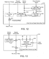
- the drive torque target calculating part 1203 has functions as shown in FIG. 12 , for example.
- the drive torque target calculating part 1203 has a multiplier 3002, a gear ratio obtaining part 3005, a real assist ratio determining part 3003, and a gear ratio controller 3004.
- the drive torque target calculating part 1203 may further have a smoothing part 3001 that smoothes the pedal input torque.
- the gear ratio obtaining part 3005 calculates the gear ratio by dividing the pedal rotation period by the rear wheel rotation period and outputs the gear ratio to the gear ratio controller 3004. If directly receiving a signal representing a gear ratio from a gear shifter or the like, the gear ratio is outputted to the gear ratio controller 3004.
- the gear ratio controller 3004 outputs the gear position (H, M, or L, for example) for assist ratio correction to the real assist ratio determining part 3003 based on the gear ratio from the gear ratio obtaining part 3005.
- the gear ratio controller 3004 may output the gear position using the vehicle speed.
- the gear ratio controller 3004 may also output the gear position for upper limit correction, separately from the gear position for assist ratio correction.
- the real assist ratio determining part 3003 determines the real assist ratio from the desired assist ratio set by the rider, the vehicle speed, and the gear position, and outputs it to the multiplier 3002.
- the multiplier 3002 calculates the assist torque value by multiplying the real assist ratio and either a smoothed pedal input torque if a smoothing part 3001 is provided or the pedal input torque itself if the smoothing part 3001 is not provided, and outputs the assist torque value.
- the real assist ratio determining part 3003 has functions as shown in FIG. 13 , for example.
- the gear shifter is a three-speed gear shifter, and that the H (high speed) position of the gear shifter has a gear ratio of 4/3, the M (mid speed) position has a gear ratio of 1, and the L (low speed) position has a gear ratio of 3/4.
- the real assist ratio determining part 3003 has a limit function output part 3301, multipliers 3302 and 3303, and an assist ratio correction coefficient selector 3304.
- the limit function output part 3301 outputs a derating function value corresponding to legal regulations shown in FIG. 14 , for example, based on the vehicle speed. In the example in FIG. 14 , a curve in which "1" is outputted up to a vehicle speed of 10km/h, and for speeds greater than that, the function value decreases linearly until it reaches 0 at 24km/h is used.
- the assist ratio correction coefficient selector 3304 outputs a correction coefficient according to a gear position when the gear position for assist ratio correction is inputted.
- a correction coefficient "d” is outputted when in the L position
- a correction coefficient "e” is outputted when in the M position
- a coefficient value is set in order to cancel the effects of the gear shifter on the assist motor torque and the assist ratio.
- the multiplier 3302 outputs the product of the desired assist ratio and the output of the limit function output part 3301 to the multiplier 3303.
- the multiplier 3303 outputs the product of the output from the multiplier 3302 and the assist ratio correction coefficient, and outputs it as the real assist ratio.
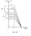
- average assist ratios such as those shown in FIG. 15 can be obtained.
- the desired assist ratio 1 where the vehicle speed is 10km/h
- the average assist ratio has a constant value of 1 regardless of the gear position.
- the average assist ratio can be made constant regardless of the gear position, and the load on the rider can be effectively reduced.
- a configuration of the present embodiment is basically similar to Embodiment 1. However, the values of the correction coefficients "d", “e”, and “f" inputted into the assist ratio correction coefficient selector 3304 of the real assist ratio determining part 3003 are different.
- the correction coefficient "d" for the L position is 8/5
- the correction coefficient "e” for the M position is 1
- the correction coefficient "f” for the H position is 5/8, for example.
- a value that is inversely proportional to the gear ratio was used, but in the present embodiment, an exponent of less than -1 is set, and a value that is proportional to a gear ratio raised to the power of this exponent is used as an example.
- the desired assist ratio 1 where the vehicle speed is 10km/h
- the gear is in the H position
- the L position is set so as to have a higher assist ratio than the H position.
- a real assist ratio determining part 3003b as shown in FIG. 17 is used instead of the real assist ratio determining part 3003 shown in FIG. 13 .
- the same reference characters are assigned for the same functions.
- the real assist ratio determining part 3003b has a limit function output part 3301, an assist ratio correction coefficient selector 3304, a multiplier 3305, an assist ratio upper limit correction coefficient selector 3306, a minimum value selector 3307, and a multiplier 3 3 09.
- correction coefficients "d", "e", and "f” inputted into the assist ratio correction coefficient selector 3304 are the same as those of Embodiment 2, and are 8/5, 1, and 5/8, respectively.
- the assist ratio upper limit correction coefficient selector 3306 selects an L position assist ratio upper limit correction coefficient "g", an M position correction coefficient "h”, or an H position correction coefficient "i” based on the upper limit correction gear position, and outputs it.
- the correction coefficient g 4/3
- the upper limit correction gear position and the assist ratio correction gear position are the same.
- the multiplier 3305 outputs the product of the desired assist ratio and the output from the assist ratio correction coefficient selector 3304.
- the minimum value selector 3307 outputs the smaller of the output from the multiplier 3305 and the output from the assist ratio upper limit correction coefficient selector 3306.
- the multiplier 3309 outputs the product of the output from the limit function output part 3301 and the output from the minimum value selector 3307, as the real assist ratio.
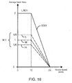
- the real assist ratio is set such that the upper limit value is reached at any gear position, as shown in FIG. 15 , based on the output from the assist ratio upper limit correction coefficient selector 3306.
- the desired assist ratio is restricted to a small value, then a real assist ratio is outputted such that the average assist ratio of the low speed L position becomes greater than that of the high speed H position as much as possible.
- the desired assist ratio is 2, then a curve 5001 is at the upper limit regardless of the gear position.
- the desired assist ratio is 1, then similar to Embodiment 2, a lower speed gear position has a higher average assist ratio than the higher speed side.
- a real assist ratio determining part 3003c as shown in FIG. 19 is used instead of the real assist ratio determining part 3003 shown in FIG. 13 .
- the same reference characters are assigned for the same functions.
- the real assist ratio determining part 3003c has a limit function output part 3301, an assist ratio correction coefficient selector 3304, an assist ratio upper limit correction coefficient selector 3306, a multiplier 3305, a multiplier 3308, and a minimum value selector 3307.
- Basic components are almost all the same as Embodiment 3, but the L position assist ratio upper limit correction coefficient "g" is 8/3, the M position assist ratio upper limit correction coefficient "h” is 2, and the H position assist ratio upper limit correction coefficient "i” is 3/2.
- the maximum allowable assist ratio is 2, and thus, values twice those of Embodiment 3 are used. This is due to the different method of connection, and as a result, the outputted real assist ratio and the resultant average assist ratio are also different.
- the output from the limit function output part 3301 is multiplied by the output of the assist ratio upper limit correction coefficient selector 3306, and thus, as long as an upper limit curve defined by the product thereof is not exceeded by the product of the desired assist ratio and the assist ratio correction coefficient, the product of the desired assist ratio and the assist ratio correction coefficient is maintained.
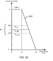
- the output of the limit function output part 3301 even after exceeding 10km/h, there are portions that are not affected by the output of the limit function output part 3301, and average assist ratios such as those shown in FIG. 20 can be attained.
- the average assist ratios change following the upper limit curve 5001 regardless of the gear position, but as in a case in which the average assist ratio in the M position is 1, for example, until the upper limit curve 5001 is reached, the average assist ratio is not affected by the limit function even if the vehicle reaches 10km/h, and the average assist ratio maintains a constant value. Also, the real assist ratio is calculated such that the average assist ratio for the L position is greater than the average assist ratio for the H position.
- a drive torque target calculating part 1203b that differs from the above-mentioned embodiments is used.
- the real assist ratio set based on a gear ratio not only is the real assist ratio set based on a gear ratio, but the smoothness of the pedal input torque is determined based on the gear ratio.
- the drive torque target calculating part 1203b has a gear ratio obtaining part 3005, a gear ratio controller 3004, a real assist ratio determining part 3003, and a smoothness controller 3006.
- the gear ratio obtaining part 3005 is similar to that of Embodiment 1.
- the gear ratio controller 3004 is also similar to that of Embodiment 1.
- the real assist ratio determining part 3003 is similar to any one of Embodiments 1 to 4.
- the smoothness controller 3006 introduced in the present embodiment calculates the assist torque from the pedal input torque, based on the gear position and the real assist ratio.
- the smoothness controller 3006 has a smoothness control coefficient selector 3601, a derating part 3602, a smoothing part 3603, an adder 3605, a multiplier 3606, a multiplier 3604, and an adder 3607.
- the smoothness control coefficient selector 3601 outputs a smoothness control coefficient "a” in the L position, a smoothness control coefficient "b” in the M position, and a smoothness control coefficient "c” in the H position, based on the gear position.
- the derating part 3602 outputs the total smoothness based on the output of the smoothness control coefficient selector 3601 and the vehicle speed.
- a total smoothness such as that shown in FIG. 23 is outputted.
- the total smoothness decreases linearly from 1 from a vehicle speed of 0 to a prescribed speed, and if the vehicle speed reaches or exceeds the prescribed vehicle speed, the total smoothness becomes 0.
- the total smoothness decreases linearly from 1/2 from a vehicle speed of 0 to a prescribed speed, and if the vehicle speed reaches or exceeds the prescribed vehicle speed, the total smoothness becomes 0.
- the total smoothness is 0 regardless of vehicle speed.
- the smoothness control coefficient "a" for the L position is 1, the smoothness control coefficient "b” for the M position is 0, and the smoothness control coefficient "c” for the H position is 0, then a total smoothness such as that shown in FIG. 24 , for example, is outputted.
- the total smoothness decreases linearly from 1 from a vehicle speed of 0 to a prescribed speed, and if the vehicle speed reaches or exceeds the prescribed vehicle speed, the total smoothness becomes 0.
- the total smoothness is 0 regardless of vehicle speed.
- the pedal input torque is smoothed in the smoothing part 3603, and a smoothed torque is thus generated.
- a reverse ripple torque is calculated by subtracting the pedal input torque from the smoothed torque.
- the multiplier 3606 generates a total ripple correction torque, which is the product of the reverse ripple torque and the total smoothness, which is the output of the derating part 3602. Meanwhile, the multiplier 3604 calculates the product of the real assist ratio and the smoothed torque.
- the adder 3607 adds the product of the real assist ratio and the smoothed torque to the total ripple correction torque to calculate the assist torque.
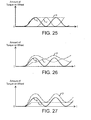
- FIG. 25 shows an example in which the average assist ratio is 1.
- the total smoothness is always set to zero, thereby flattening the assist torque "r." This makes it possible to minimize the amount of power consumption lost in the motor or the drive inverter.
- gear position output is outputted from the gear shifter itself or if the gear position output is directly outputted from a gear shift lever or a control panel, then it is always possible to obtain information on gear position.
- gear ratio obtaining part 3005 is made so as to obtain the gear ratio or gear position based on the ratio of the pedal rotation period and the wheel rotation period or the like, then if pedaling is stopped while running or the bike is stopped, then the gear position is temporarily unknown. After continuous pedaling is resumed, the gear ratio or the gear position is detected after a few pulses of the pedal rotation detection pulse (after the pedal has rotated 60°, for example).
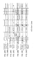
- FIG. 28 An example of a vehicle in motion is shown in FIG. 28 .
- the average pedal input torque shown in FIG. 28A and the number of pedal rotations shown in FIG. 28B there are three periods over which pedaling takes place.
- FIG. 28C shows an actual gear position.
- DC don't care
- DC represents a portion in which there is no assist and the gear ratio does not have much real effect no matter what the gear ratio is, due to the fact that there is no pedal input torque in this portion.
- the gear ratio controller 3004 when the gear ratio controller 3004 receives output from the gear ratio obtaining part 3005 representing that the gear ratio is unknown, the gear ratio controller 3004 outputs a gear position for assist ratio correction as shown in FIG. 28F , and outputs a gear position for assist ratio upper limit correction as shown in FIG. 28G .
- the real assist ratio is set lower for the H position than the L position, and thus, as shown in FIG. 28G , during the temporarily unknown period, the gear position for assist ratio upper limit correction that affects the upper limit of the real assist ratio is set to the H position.
- the gear ratio may be assumed to be the H position for other unknown periods.
- the gear position for assist ratio correction may be assumed to be at the L position, for example.
- the average assist ratio is set so as to be high, which allows a smooth start of pedaling. For example, during the tail end of the "unknown period 1", there is a period in which such settings are used.
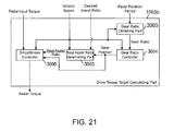
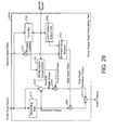
- the drive torque target calculating part 1203c has a smoothing part 3101, a multiplier 3102, an adder 3104, a multiplier 3105, an adder 3103, a vehicle speed derating part 3108, a multiplier 3107, a controller 3106, a limit function output part 3109, and a minimum value selector 3110.
- the smoothing part 3101 calculates the smoothed torque by smoothing the pedal input torque.
- the adder 3104 outputs the reverse ripple torque by making the calculation of: smoothed torque - pedal input torque.
- the multiplier 3105 calculates the product of the reverse ripple torque and the output from the vehicle speed derating part 3108 (total smoothness), and outputs the total ripple correction torque.
- the multiplier 3102 calculates the product of the smoothed torque and the real assist ratio, which is the output of the minimum value selector 3110, and outputs it.
- the adder 3103 outputs the assist torque, which is the sum of the product of the smoothed torque and the real assist ratio, and the total ripple correction torque. Such calculations are similar to those of the smoothness controller 3006 in Embodiment 5.
- the controller 3106 calculates the gear ratio based on the pedal input torque and the vehicle speed, and outputs the correction coefficient and the total smoothness corresponding to the calculated gear ratio. Specifically, if the vehicle speed is lower than a prescribed speed, it outputs values corresponding to the L position. Also, it outputs values corresponding to the L position from the start of pedaling (from when the pedal input torque is 0 or a small value) until a fixed time. The controller 3106 outputs values corresponding to the M position in other cases. However, if there is pedal input torque and the vehicle speed is above a threshold, then the controller 3106 may output values corresponding to the H position.
- a correction coefficient of 8/5 is outputted for the L position
- a correction coefficient of 1 is outputted for the M position
- a correction coefficient of 5/8 is outputted for the H position.
- the correction coefficient changes based on estimated position changes, the correction coefficient is changed gradually and outputted, such that the correction coefficient changes continuously.
- the coefficient for the total smoothness may be 1 in the L position and 0 in the M position or the H position, as in Embodiment 5.
- a coefficient of 1 may be outputted for the L position, 1/2 may be outputted for the M position, and 0 may be outputted for the H position.
- the vehicle speed derating part 3108 follows a curve shown in FIG. 23 or 24 and outputs the total smoothness corresponding to the coefficient based on the vehicle speed, similar to the derating part 3602 in Embodiment 5.
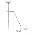
- the limit function output part 3109 of the present embodiment outputs an upper limit value for the real assist ratio according to vehicle speed. It outputs values as shown in FIG. 30 , for example. In the example in FIG. 30 , it outputs 3/2 up to vehicle speeds of 10km/h, and between 10km/h and 24km/h inclusive, the outputted value decreases linearly down to 0.
- the minimum value selector 3110 outputs the smaller of the output of the multiplier 3107 (product of desired assist ratio and correction coefficient) and the output of the limit function output part 3109 as the real assist ratio to the multiplier 3102.
- FIG. 31 A running example shown in FIG. 31 will be described, for example.
- pedaling begins from a standstill, pedaling is stopped momentarily without the bicycle stopping, and pedaling begins again. This is clear from the average pedal input torque of FIG. 31A , the number of pedal rotations in FIG. 31B , and the vehicle speed of FIG. 31C .
- the gear position for assist ratio correction assumed to be the L position.
- the gear position is assumed to be the M position for other portions.
- a correction coefficient is determined based on the assumed gear position.
- the limit function output part 3109 as shown in FIG. 31F , always assumes the H position and outputs the upper limit value of the real assist.
- the total smoothness outputted by the vehicle speed derating part 3108 becomes, as shown in the period T 1 in FIG. 31G , 1 when in the L position and the vehicle speed is 0 or a small value, and gradually decreases to 0 as the vehicle speed increases.
- the total smoothness remains 0. In the M position or the H position, the total smoothness remains 0.
- Embodiments 1 to 7 examples were shown in which the drive torque target calculating part 1203 is applied for feed forward control, but it is also possible to use this drive torque target calculating part 1203 for feedback control.
- a configuration of a calculating part 1021 shown in FIG. 32 is used.
- This calculating part 1021 has a regenerative brake target torque calculating part 11201, a regeneration activation part 11202, a drive torque target calculating part 11203, an assist activation part 11204, an adder 11206, a torque slew rate limiter 11255, a corresponding torque converter 11251, an adder 11252, a loop filter part 11253, and a PWM code generator 11254.
- the vehicle speed and the rotation period of the wheel from the vehicle speed input part 1024, the pedal torque value from the torque input part 1027, and the pedal rotation input from the pedal rotation input part 1022 are inputted into the drive torque target calculating part 11203, thus calculating the assist torque value.
- the calculation performed by the drive torque target calculating part 11203 is similar to that in the drive torque target calculating part 1203.
- the regenerative brake target torque calculating part 11201 calculates a regenerative brake target torque value according to a curve set in advance, for example, based on the vehicle speed value from the vehicle speed input part 1024.
- the curve represents a relation in which the curve has reversed polarity to the vehicle speed value and is half or less ("half or less” sometimes includes cases in which the curve exceeds "half" by a few percentage points, for example) of the absolute value of the vehicle speed. By doing so, no matter what the speed, regeneration can occur at a certain efficiency. This process is not the main point of the present embodiment and therefore will not be described any further.
- the regeneration activation part 11202 if an input signal representing the fact that the brake is active is inputted from the brake input part 1028, then the regeneration activation part 11202 outputs a regenerative brake target torque value from the regenerative brake target torque calculating part 11201 to the adder 11206. In other cases, the regeneration activation part 11202 outputs 0.
- the assist activation part 11204 if an input signal signifying that the brake is not active is inputted from the brake input part 1028, then the assist activation part 11204 outputs an assist torque value from the drive torque target calculating part 11203. In other cases, the assist activation part 11204 outputs 0.
- the adder 11206 reverses the polarity of the regenerative brake target torque value from the regeneration activation part 11202 and then outputs it, but outputs the assist torque value from the assist activation part 11204 as is.
- the assist torque value and the regenerative brake target torque value will be referred to as a target torque value below.
- the torque slew rate limiter 11255 conducts a well-known slew rate limiting process on the target torque value from the adder 11206, and outputs the result thereof to the adder 11252.
- the corresponding torque converter 11251 conducts a conversion process that converts a value corresponding to a motor current from the current detector 1023 to a corresponding torque value, and outputs the result thereof to the adder 11252.
- the adder 11252 subtracts an output from the corresponding torque converter 11251 from the output from the torque slew rate limiter 11255, and outputs the calculation result to the loop filter part 11253.
- the loop filter part 11253 conducts integration on the output from the adder 11252 and outputs the result thereof to the PWM code generator 11254.
- the PWM code generator 11254 multiplies the output from the loop filter part 11253 by a battery voltage/reference voltage (24V, for example) from the AD input part 1029 and generates a PWM code.
- the PWM code is outputted to the motor drive timing generator 1026.
- Embodiments of the present invention were described above, but the present invention is not limited thereto.
- the above-mentioned function block diagram divides functions into blocks for ease of description, but this sometimes differs from the actual circuit configuration.
- when using a program there are cases in which these functions do not correspond to program modules.
- there are a plurality of specific calculation methods for realizing the above-mentioned functions any of which may be used.
Landscapes
- Engineering & Computer Science (AREA)
- Transportation (AREA)
- Mechanical Engineering (AREA)
- Chemical & Material Sciences (AREA)
- Combustion & Propulsion (AREA)
- Power Engineering (AREA)
- Electric Propulsion And Braking For Vehicles (AREA)
Applications Claiming Priority (1)
| Application Number | Priority Date | Filing Date | Title |
|---|---|---|---|
| JP2012114264A JP5689849B2 (ja) | 2012-05-18 | 2012-05-18 | モータ駆動制御装置 |
Publications (2)
| Publication Number | Publication Date |
|---|---|
| EP2664535A1 true EP2664535A1 (fr) | 2013-11-20 |
| EP2664535B1 EP2664535B1 (fr) | 2017-12-27 |
Family
ID=48484973
Family Applications (1)
| Application Number | Title | Priority Date | Filing Date |
|---|---|---|---|
| EP13002506.7A Not-in-force EP2664535B1 (fr) | 2012-05-18 | 2013-05-13 | Dispositif de contrôle d'un moteur |
Country Status (5)
| Country | Link |
|---|---|
| US (1) | US9114850B2 (fr) |
| EP (1) | EP2664535B1 (fr) |
| JP (1) | JP5689849B2 (fr) |
| CN (1) | CN103466033B (fr) |
| TW (1) | TWI533590B (fr) |
Cited By (3)
| Publication number | Priority date | Publication date | Assignee | Title |
|---|---|---|---|---|
| EP3342697A1 (fr) * | 2016-12-28 | 2018-07-04 | Robert Bosch GmbH | Procédé de réduction de l'effet de retour dans des bicyclettes électriques et bicyclette électrique |
| WO2021023919A1 (fr) * | 2019-08-07 | 2021-02-11 | Mavic S.A.S | Procédé automatique de commande en courant d'un moteur d'assistance au pédalage sur un vélo à assistance électrique et vélo à assistance électrique prévu pour la mise en oeuvre d'un tel procédé |
| US11097806B2 (en) | 2016-05-30 | 2021-08-24 | Robert Bosch Gmbh | Control method and devices for controlling the electric motor of an electric bicycle |
Families Citing this family (34)
| Publication number | Priority date | Publication date | Assignee | Title |
|---|---|---|---|---|
| TW201315650A (zh) * | 2011-10-11 | 2013-04-16 | 久鼎金屬實業股份有限公司 | 具有順暢變速功能之助力自行車 |
| DE102013220541B4 (de) * | 2013-10-11 | 2015-05-21 | Continental Automotive Gmbh | Verfahren zur Erfassung eines Schaltvorgangs eines Schaltgetriebes eines Fahrrads und Verfahren zur Leistungssteuerung eines Hilfsantriebs eines Fahrrads |
| JP5869620B2 (ja) * | 2014-05-23 | 2016-02-24 | 株式会社シマノ | 自転車用電動構成部品 |
| JP6321558B2 (ja) * | 2015-01-15 | 2018-05-09 | 株式会社シマノ | 自転車用アシスト装置の制御装置、および、自転車用アシスト装置 |
| JP6427433B2 (ja) * | 2015-02-03 | 2018-11-21 | マイクロスペース株式会社 | モータ駆動装置 |
| WO2016125789A1 (fr) * | 2015-02-06 | 2016-08-11 | ヤマハ発動機株式会社 | Véhicule de promenade à selle |
| JP6460851B2 (ja) * | 2015-03-12 | 2019-01-30 | ブリヂストンサイクル株式会社 | 電動アシスト自転車 |
| US9573654B2 (en) * | 2015-04-28 | 2017-02-21 | Shimano Inc. | Bicycle controller |
| US9896152B2 (en) * | 2015-05-25 | 2018-02-20 | Shimano Inc. | Bicycle transmission system |
| DE102016209570B3 (de) * | 2016-06-01 | 2017-08-24 | Robert Bosch Gmbh | Steuerungsverfahren und Steuergerät zur Anpassung einer Geschwindigkeit der Schiebehilfe eines Elektrofahrrads |
| JP6933885B2 (ja) * | 2016-06-21 | 2021-09-08 | ヤマハ発動機株式会社 | 電動補助車両および補助出力制御システム |
| JP6670734B2 (ja) * | 2016-10-31 | 2020-03-25 | 株式会社シマノ | 自転車用制御装置およびこれを含む自転車用制御システム |
| JP6916047B2 (ja) * | 2017-06-16 | 2021-08-11 | 株式会社シマノ | 自転車用制御装置 |
| JPWO2019053889A1 (ja) | 2017-09-15 | 2020-09-17 | ヤマハ発動機株式会社 | 電動補助システムおよび電動補助車両 |
| JP7171953B2 (ja) * | 2017-09-15 | 2022-11-15 | ヤマハ発動機株式会社 | 電動補助システムおよび電動補助車両 |
| JP7343266B2 (ja) | 2017-10-27 | 2023-09-12 | 株式会社シマノ | 人力駆動車両用制御装置 |
| JP6941541B2 (ja) * | 2017-11-16 | 2021-09-29 | 株式会社シマノ | 人力駆動車両用制御装置 |
| JP7045238B2 (ja) * | 2018-03-29 | 2022-03-31 | 株式会社シマノ | 人力駆動車用制御装置 |
| JP7244737B2 (ja) * | 2018-09-27 | 2023-03-23 | ミツミ電機株式会社 | モータ制御回路及びモータ制御装置 |
| JP7277120B2 (ja) * | 2018-12-03 | 2023-05-18 | 株式会社シマノ | 人力駆動車用の制御装置 |
| US11518472B2 (en) | 2019-02-15 | 2022-12-06 | Sram, Llc | Bicycle control system |
| US11530015B2 (en) | 2019-02-15 | 2022-12-20 | Sram, Llc | Bicycle control system |
| US11738826B2 (en) | 2019-02-15 | 2023-08-29 | Sram, Llc | Bicycle control system |
| US12208858B2 (en) | 2019-02-15 | 2025-01-28 | Sram, Llc | Bicycle control system |
| CN109911097B (zh) * | 2019-04-04 | 2020-10-20 | 深圳市瑞源祥橡塑制品有限公司 | 一种控制自行车车轮转动的方法及自行车 |
| JP7514605B2 (ja) * | 2019-05-17 | 2024-07-11 | 株式会社シマノ | 人力駆動車用の制御装置 |
| CN112706871B (zh) * | 2019-10-24 | 2022-06-21 | 睿能创意公司 | 电动助力车、传动装置及控制方法 |
| JP7039545B2 (ja) * | 2019-12-27 | 2022-03-22 | ヤマハ発動機株式会社 | 電動補助自転車、その駆動システム、及び制御方法 |
| CN112550546B (zh) * | 2020-11-23 | 2022-04-15 | 江苏科技大学 | 一种电动车助力运行控制系统及其控制方法 |
| TWI790579B (zh) * | 2021-03-25 | 2023-01-21 | 宏碁股份有限公司 | 用於電動輔助腳踏車的驅動裝置以及驅動方法 |
| JP7769523B2 (ja) * | 2021-11-19 | 2025-11-13 | カワサキモータース株式会社 | 鞍乗車両、車両の制御方法及び制御プログラム |
| DE102023210333A1 (de) * | 2023-10-19 | 2025-04-24 | Robert Bosch Gesellschaft mit beschränkter Haftung | Verfahren zum Betreiben einer Antriebseinheit eines Elektrofahrrads |
| JP2025111336A (ja) * | 2024-01-17 | 2025-07-30 | ミネベアミツミ株式会社 | 電動アシスト自転車および電動アシスト自転車の変速比の判定方法 |
| CN119483371B (zh) * | 2025-01-16 | 2025-04-11 | 深圳市赢锋智能技术有限公司 | 一种电机控制方法、系统和电动助力车辆 |
Citations (8)
| Publication number | Priority date | Publication date | Assignee | Title |
|---|---|---|---|---|
| JPH0880891A (ja) * | 1994-09-13 | 1996-03-26 | Yamaha Motor Co Ltd | 補助動力付き人力車両 |
| JPH09286376A (ja) * | 1996-04-19 | 1997-11-04 | Yamaha Motor Co Ltd | 電動モータ付き乗り物およびその制御方法 |
| EP0825102A2 (fr) * | 1996-08-20 | 1998-02-25 | Sanyo Electric Co., Ltd. | Dispositif limiteur de couple pour moteurs dans des véhicules à propulsion électrique |
| JP3190491B2 (ja) | 1993-07-23 | 2001-07-23 | ヤマハ発動機株式会社 | 電動モータ付き乗り物 |
| EP1129934A2 (fr) * | 2000-03-01 | 2001-09-05 | Honda Giken Kogyo Kabushiki Kaisha | Bicyclette à moteur |
| EP1415904A2 (fr) * | 2002-10-30 | 2004-05-06 | Sanyo Electric Co., Ltd. | Bicyclette assistée par un moteur électrique |
| EP2394902A1 (fr) * | 2010-06-11 | 2011-12-14 | Shimano Inc. | Bicyclette avec moteur auxiliaire et dispositif de commande |
| EP2447108A1 (fr) * | 2010-10-29 | 2012-05-02 | Shimano, Inc. | Système de contrôle de moteur de bicyclette |
Family Cites Families (13)
| Publication number | Priority date | Publication date | Assignee | Title |
|---|---|---|---|---|
| DE69233024T2 (de) * | 1991-06-04 | 2003-10-16 | Yamaha Hatsudoki K.K., Iwata | Muskelgetriebenes Fahrzeug |
| JP3468843B2 (ja) * | 1994-05-13 | 2003-11-17 | ヤマハ発動機株式会社 | 電動モータ付き自転車およびその制御方法 |
| JP3306309B2 (ja) * | 1996-08-28 | 2002-07-24 | 三洋電機株式会社 | アシスト式電動車 |
| JP3424577B2 (ja) | 1998-09-01 | 2003-07-07 | トヨタ自動車株式会社 | 車両の駆動制御装置 |
| JP5025851B2 (ja) * | 2001-02-14 | 2012-09-12 | ヤマハ発動機株式会社 | 電動補助車両の補助動力制御装置 |
| US6516908B2 (en) * | 2001-05-10 | 2003-02-11 | Merida Industry Co., Ltd. | Transmission for an electric bicycle |
| JP2003104278A (ja) * | 2001-09-28 | 2003-04-09 | Honda Motor Co Ltd | 電動補助自転車 |
| JP4229718B2 (ja) * | 2003-02-14 | 2009-02-25 | ヤマハ発動機株式会社 | 電動補助車両の補助力制御装置 |
| US7706935B2 (en) * | 2004-09-14 | 2010-04-27 | Systemes D'energie Et Propulsion Eps Inc. | Energy management system for motor-assisted user-propelled vehicles |
| DE502006003191D1 (de) * | 2005-05-13 | 2009-04-30 | Spinwood Trading & Consulting | Fahrzeug |
| US7547021B2 (en) * | 2006-09-22 | 2009-06-16 | Nirve Sports, Ltd. | Propelled bicycle with automatic transmission |
| JP4344379B2 (ja) | 2006-12-06 | 2009-10-14 | ジヤトコ株式会社 | 無段変速機の制御装置 |
| JP5496158B2 (ja) * | 2011-08-29 | 2014-05-21 | 株式会社シマノ | 自転車用制御装置 |
-
2012
- 2012-05-18 JP JP2012114264A patent/JP5689849B2/ja active Active
-
2013
- 2013-03-27 US US13/851,308 patent/US9114850B2/en active Active
- 2013-04-11 TW TW102112916A patent/TWI533590B/zh active
- 2013-05-13 EP EP13002506.7A patent/EP2664535B1/fr not_active Not-in-force
- 2013-05-16 CN CN201310181970.1A patent/CN103466033B/zh active Active
Patent Citations (8)
| Publication number | Priority date | Publication date | Assignee | Title |
|---|---|---|---|---|
| JP3190491B2 (ja) | 1993-07-23 | 2001-07-23 | ヤマハ発動機株式会社 | 電動モータ付き乗り物 |
| JPH0880891A (ja) * | 1994-09-13 | 1996-03-26 | Yamaha Motor Co Ltd | 補助動力付き人力車両 |
| JPH09286376A (ja) * | 1996-04-19 | 1997-11-04 | Yamaha Motor Co Ltd | 電動モータ付き乗り物およびその制御方法 |
| EP0825102A2 (fr) * | 1996-08-20 | 1998-02-25 | Sanyo Electric Co., Ltd. | Dispositif limiteur de couple pour moteurs dans des véhicules à propulsion électrique |
| EP1129934A2 (fr) * | 2000-03-01 | 2001-09-05 | Honda Giken Kogyo Kabushiki Kaisha | Bicyclette à moteur |
| EP1415904A2 (fr) * | 2002-10-30 | 2004-05-06 | Sanyo Electric Co., Ltd. | Bicyclette assistée par un moteur électrique |
| EP2394902A1 (fr) * | 2010-06-11 | 2011-12-14 | Shimano Inc. | Bicyclette avec moteur auxiliaire et dispositif de commande |
| EP2447108A1 (fr) * | 2010-10-29 | 2012-05-02 | Shimano, Inc. | Système de contrôle de moteur de bicyclette |
Cited By (5)
| Publication number | Priority date | Publication date | Assignee | Title |
|---|---|---|---|---|
| US11097806B2 (en) | 2016-05-30 | 2021-08-24 | Robert Bosch Gmbh | Control method and devices for controlling the electric motor of an electric bicycle |
| EP3342697A1 (fr) * | 2016-12-28 | 2018-07-04 | Robert Bosch GmbH | Procédé de réduction de l'effet de retour dans des bicyclettes électriques et bicyclette électrique |
| WO2021023919A1 (fr) * | 2019-08-07 | 2021-02-11 | Mavic S.A.S | Procédé automatique de commande en courant d'un moteur d'assistance au pédalage sur un vélo à assistance électrique et vélo à assistance électrique prévu pour la mise en oeuvre d'un tel procédé |
| FR3099747A1 (fr) * | 2019-08-07 | 2021-02-12 | Mavic Sas | Procédé automatique de commande en courant d’un moteur d’assistance au pédalage sur un vélo à assistance électrique et vélo à assistance électrique prévu pour la mise en œuvre d’un tel procédé |
| US12275494B2 (en) | 2019-08-07 | 2025-04-15 | Mavic Group | Automatic method for controlling in current-mode a motor for assisting with pedalling on an electrically assisted pedal cycle and electrically assisted pedal cycle intended to implement such a method |
Also Published As
| Publication number | Publication date |
|---|---|
| TWI533590B (zh) | 2016-05-11 |
| US9114850B2 (en) | 2015-08-25 |
| JP2013241045A (ja) | 2013-12-05 |
| CN103466033A (zh) | 2013-12-25 |
| EP2664535B1 (fr) | 2017-12-27 |
| CN103466033B (zh) | 2017-05-31 |
| US20130311019A1 (en) | 2013-11-21 |
| JP5689849B2 (ja) | 2015-03-25 |
| TW201351873A (zh) | 2013-12-16 |
Similar Documents
| Publication | Publication Date | Title |
|---|---|---|
| US9114850B2 (en) | Motor drive control device | |
| EP2669168B1 (fr) | Dispositif de commande de direction de moteur | |
| US10040508B2 (en) | Motor driving control apparatus | |
| JP6178440B2 (ja) | モータ駆動制御装置 | |
| US9136780B2 (en) | Controller for driving a motor and electric power-assisted vehicle | |
| JP2017525615A (ja) | ペダル車両用パワートレイン | |
| US9902462B2 (en) | Controller for driving a motor, and electric power assisted vehicle | |
| TWI599497B (zh) | Motor drive control device |
Legal Events
| Date | Code | Title | Description |
|---|---|---|---|
| PUAI | Public reference made under article 153(3) epc to a published international application that has entered the european phase |
Free format text: ORIGINAL CODE: 0009012 |
|
| AK | Designated contracting states |
Kind code of ref document: A1 Designated state(s): AL AT BE BG CH CY CZ DE DK EE ES FI FR GB GR HR HU IE IS IT LI LT LU LV MC MK MT NL NO PL PT RO RS SE SI SK SM TR |
|
| AX | Request for extension of the european patent |
Extension state: BA ME |
|
| 17P | Request for examination filed |
Effective date: 20140516 |
|
| RBV | Designated contracting states (corrected) |
Designated state(s): AL AT BE BG CH CY CZ DE DK EE ES FI FR GB GR HR HU IE IS IT LI LT LU LV MC MK MT NL NO PL PT RO RS SE SI SK SM TR |
|
| 17Q | First examination report despatched |
Effective date: 20151217 |
|
| GRAP | Despatch of communication of intention to grant a patent |
Free format text: ORIGINAL CODE: EPIDOSNIGR1 |
|
| INTG | Intention to grant announced |
Effective date: 20170717 |
|
| GRAS | Grant fee paid |
Free format text: ORIGINAL CODE: EPIDOSNIGR3 |
|
| GRAA | (expected) grant |
Free format text: ORIGINAL CODE: 0009210 |
|
| AK | Designated contracting states |
Kind code of ref document: B1 Designated state(s): AL AT BE BG CH CY CZ DE DK EE ES FI FR GB GR HR HU IE IS IT LI LT LU LV MC MK MT NL NO PL PT RO RS SE SI SK SM TR |
|
| REG | Reference to a national code |
Ref country code: GB Ref legal event code: FG4D |
|
| REG | Reference to a national code |
Ref country code: CH Ref legal event code: EP |
|
| REG | Reference to a national code |
Ref country code: AT Ref legal event code: REF Ref document number: 958025 Country of ref document: AT Kind code of ref document: T Effective date: 20180115 |
|
| REG | Reference to a national code |
Ref country code: IE Ref legal event code: FG4D |
|
| REG | Reference to a national code |
Ref country code: DE Ref legal event code: R096 Ref document number: 602013031260 Country of ref document: DE |
|
| REG | Reference to a national code |
Ref country code: NL Ref legal event code: FP |
|
| PG25 | Lapsed in a contracting state [announced via postgrant information from national office to epo] |
Ref country code: LT Free format text: LAPSE BECAUSE OF FAILURE TO SUBMIT A TRANSLATION OF THE DESCRIPTION OR TO PAY THE FEE WITHIN THE PRESCRIBED TIME-LIMIT Effective date: 20171227 Ref country code: NO Free format text: LAPSE BECAUSE OF FAILURE TO SUBMIT A TRANSLATION OF THE DESCRIPTION OR TO PAY THE FEE WITHIN THE PRESCRIBED TIME-LIMIT Effective date: 20180327 Ref country code: FI Free format text: LAPSE BECAUSE OF FAILURE TO SUBMIT A TRANSLATION OF THE DESCRIPTION OR TO PAY THE FEE WITHIN THE PRESCRIBED TIME-LIMIT Effective date: 20171227 |
|
| REG | Reference to a national code |
Ref country code: LT Ref legal event code: MG4D |
|
| REG | Reference to a national code |
Ref country code: AT Ref legal event code: MK05 Ref document number: 958025 Country of ref document: AT Kind code of ref document: T Effective date: 20171227 |
|
| PG25 | Lapsed in a contracting state [announced via postgrant information from national office to epo] |
Ref country code: HR Free format text: LAPSE BECAUSE OF FAILURE TO SUBMIT A TRANSLATION OF THE DESCRIPTION OR TO PAY THE FEE WITHIN THE PRESCRIBED TIME-LIMIT Effective date: 20171227 Ref country code: BG Free format text: LAPSE BECAUSE OF FAILURE TO SUBMIT A TRANSLATION OF THE DESCRIPTION OR TO PAY THE FEE WITHIN THE PRESCRIBED TIME-LIMIT Effective date: 20180327 Ref country code: GR Free format text: LAPSE BECAUSE OF FAILURE TO SUBMIT A TRANSLATION OF THE DESCRIPTION OR TO PAY THE FEE WITHIN THE PRESCRIBED TIME-LIMIT Effective date: 20180328 Ref country code: LV Free format text: LAPSE BECAUSE OF FAILURE TO SUBMIT A TRANSLATION OF THE DESCRIPTION OR TO PAY THE FEE WITHIN THE PRESCRIBED TIME-LIMIT Effective date: 20171227 Ref country code: RS Free format text: LAPSE BECAUSE OF FAILURE TO SUBMIT A TRANSLATION OF THE DESCRIPTION OR TO PAY THE FEE WITHIN THE PRESCRIBED TIME-LIMIT Effective date: 20171227 |
|
| PG25 | Lapsed in a contracting state [announced via postgrant information from national office to epo] |
Ref country code: SK Free format text: LAPSE BECAUSE OF FAILURE TO SUBMIT A TRANSLATION OF THE DESCRIPTION OR TO PAY THE FEE WITHIN THE PRESCRIBED TIME-LIMIT Effective date: 20171227 Ref country code: EE Free format text: LAPSE BECAUSE OF FAILURE TO SUBMIT A TRANSLATION OF THE DESCRIPTION OR TO PAY THE FEE WITHIN THE PRESCRIBED TIME-LIMIT Effective date: 20171227 Ref country code: CY Free format text: LAPSE BECAUSE OF FAILURE TO SUBMIT A TRANSLATION OF THE DESCRIPTION OR TO PAY THE FEE WITHIN THE PRESCRIBED TIME-LIMIT Effective date: 20171227 Ref country code: CZ Free format text: LAPSE BECAUSE OF FAILURE TO SUBMIT A TRANSLATION OF THE DESCRIPTION OR TO PAY THE FEE WITHIN THE PRESCRIBED TIME-LIMIT Effective date: 20171227 Ref country code: ES Free format text: LAPSE BECAUSE OF FAILURE TO SUBMIT A TRANSLATION OF THE DESCRIPTION OR TO PAY THE FEE WITHIN THE PRESCRIBED TIME-LIMIT Effective date: 20171227 |
|
| PG25 | Lapsed in a contracting state [announced via postgrant information from national office to epo] |
Ref country code: IS Free format text: LAPSE BECAUSE OF FAILURE TO SUBMIT A TRANSLATION OF THE DESCRIPTION OR TO PAY THE FEE WITHIN THE PRESCRIBED TIME-LIMIT Effective date: 20180427 Ref country code: SM Free format text: LAPSE BECAUSE OF FAILURE TO SUBMIT A TRANSLATION OF THE DESCRIPTION OR TO PAY THE FEE WITHIN THE PRESCRIBED TIME-LIMIT Effective date: 20171227 Ref country code: IT Free format text: LAPSE BECAUSE OF FAILURE TO SUBMIT A TRANSLATION OF THE DESCRIPTION OR TO PAY THE FEE WITHIN THE PRESCRIBED TIME-LIMIT Effective date: 20171227 Ref country code: AT Free format text: LAPSE BECAUSE OF FAILURE TO SUBMIT A TRANSLATION OF THE DESCRIPTION OR TO PAY THE FEE WITHIN THE PRESCRIBED TIME-LIMIT Effective date: 20171227 Ref country code: RO Free format text: LAPSE BECAUSE OF FAILURE TO SUBMIT A TRANSLATION OF THE DESCRIPTION OR TO PAY THE FEE WITHIN THE PRESCRIBED TIME-LIMIT Effective date: 20171227 Ref country code: PL Free format text: LAPSE BECAUSE OF FAILURE TO SUBMIT A TRANSLATION OF THE DESCRIPTION OR TO PAY THE FEE WITHIN THE PRESCRIBED TIME-LIMIT Effective date: 20171227 |
|
| REG | Reference to a national code |
Ref country code: DE Ref legal event code: R097 Ref document number: 602013031260 Country of ref document: DE |
|
| PLBE | No opposition filed within time limit |
Free format text: ORIGINAL CODE: 0009261 |
|
| STAA | Information on the status of an ep patent application or granted ep patent |
Free format text: STATUS: NO OPPOSITION FILED WITHIN TIME LIMIT |
|
| PG25 | Lapsed in a contracting state [announced via postgrant information from national office to epo] |
Ref country code: DK Free format text: LAPSE BECAUSE OF FAILURE TO SUBMIT A TRANSLATION OF THE DESCRIPTION OR TO PAY THE FEE WITHIN THE PRESCRIBED TIME-LIMIT Effective date: 20171227 |
|
| 26N | No opposition filed |
Effective date: 20180928 |
|
| REG | Reference to a national code |
Ref country code: CH Ref legal event code: PL |
|
| GBPC | Gb: european patent ceased through non-payment of renewal fee |
Effective date: 20180513 |
|
| REG | Reference to a national code |
Ref country code: BE Ref legal event code: MM Effective date: 20180531 |
|
| PG25 | Lapsed in a contracting state [announced via postgrant information from national office to epo] |
Ref country code: MC Free format text: LAPSE BECAUSE OF FAILURE TO SUBMIT A TRANSLATION OF THE DESCRIPTION OR TO PAY THE FEE WITHIN THE PRESCRIBED TIME-LIMIT Effective date: 20171227 |
|
| REG | Reference to a national code |
Ref country code: IE Ref legal event code: MM4A |
|
| PG25 | Lapsed in a contracting state [announced via postgrant information from national office to epo] |
Ref country code: SI Free format text: LAPSE BECAUSE OF FAILURE TO SUBMIT A TRANSLATION OF THE DESCRIPTION OR TO PAY THE FEE WITHIN THE PRESCRIBED TIME-LIMIT Effective date: 20171227 Ref country code: LI Free format text: LAPSE BECAUSE OF NON-PAYMENT OF DUE FEES Effective date: 20180531 Ref country code: CH Free format text: LAPSE BECAUSE OF NON-PAYMENT OF DUE FEES Effective date: 20180531 |
|
| PG25 | Lapsed in a contracting state [announced via postgrant information from national office to epo] |
Ref country code: LU Free format text: LAPSE BECAUSE OF NON-PAYMENT OF DUE FEES Effective date: 20180513 |
|
| PG25 | Lapsed in a contracting state [announced via postgrant information from national office to epo] |
Ref country code: IE Free format text: LAPSE BECAUSE OF NON-PAYMENT OF DUE FEES Effective date: 20180513 Ref country code: GB Free format text: LAPSE BECAUSE OF NON-PAYMENT OF DUE FEES Effective date: 20180513 Ref country code: FR Free format text: LAPSE BECAUSE OF NON-PAYMENT OF DUE FEES Effective date: 20180531 |
|
| PG25 | Lapsed in a contracting state [announced via postgrant information from national office to epo] |
Ref country code: BE Free format text: LAPSE BECAUSE OF NON-PAYMENT OF DUE FEES Effective date: 20180531 |
|
| PG25 | Lapsed in a contracting state [announced via postgrant information from national office to epo] |
Ref country code: MT Free format text: LAPSE BECAUSE OF NON-PAYMENT OF DUE FEES Effective date: 20180513 |
|
| PG25 | Lapsed in a contracting state [announced via postgrant information from national office to epo] |
Ref country code: TR Free format text: LAPSE BECAUSE OF FAILURE TO SUBMIT A TRANSLATION OF THE DESCRIPTION OR TO PAY THE FEE WITHIN THE PRESCRIBED TIME-LIMIT Effective date: 20171227 |
|
| PG25 | Lapsed in a contracting state [announced via postgrant information from national office to epo] |
Ref country code: PT Free format text: LAPSE BECAUSE OF FAILURE TO SUBMIT A TRANSLATION OF THE DESCRIPTION OR TO PAY THE FEE WITHIN THE PRESCRIBED TIME-LIMIT Effective date: 20171227 Ref country code: HU Free format text: LAPSE BECAUSE OF FAILURE TO SUBMIT A TRANSLATION OF THE DESCRIPTION OR TO PAY THE FEE WITHIN THE PRESCRIBED TIME-LIMIT; INVALID AB INITIO Effective date: 20130513 |
|
| PG25 | Lapsed in a contracting state [announced via postgrant information from national office to epo] |
Ref country code: MK Free format text: LAPSE BECAUSE OF NON-PAYMENT OF DUE FEES Effective date: 20171227 Ref country code: SE Free format text: LAPSE BECAUSE OF FAILURE TO SUBMIT A TRANSLATION OF THE DESCRIPTION OR TO PAY THE FEE WITHIN THE PRESCRIBED TIME-LIMIT Effective date: 20171227 |
|
| PG25 | Lapsed in a contracting state [announced via postgrant information from national office to epo] |
Ref country code: AL Free format text: LAPSE BECAUSE OF FAILURE TO SUBMIT A TRANSLATION OF THE DESCRIPTION OR TO PAY THE FEE WITHIN THE PRESCRIBED TIME-LIMIT Effective date: 20171227 |
|
| PGFP | Annual fee paid to national office [announced via postgrant information from national office to epo] |
Ref country code: NL Payment date: 20220420 Year of fee payment: 10 |
|
| PGFP | Annual fee paid to national office [announced via postgrant information from national office to epo] |
Ref country code: DE Payment date: 20220329 Year of fee payment: 10 |
|
| REG | Reference to a national code |
Ref country code: DE Ref legal event code: R119 Ref document number: 602013031260 Country of ref document: DE |
|
| REG | Reference to a national code |
Ref country code: NL Ref legal event code: MM Effective date: 20230601 |
|
| PG25 | Lapsed in a contracting state [announced via postgrant information from national office to epo] |
Ref country code: NL Free format text: LAPSE BECAUSE OF NON-PAYMENT OF DUE FEES Effective date: 20230601 |
|
| PG25 | Lapsed in a contracting state [announced via postgrant information from national office to epo] |
Ref country code: DE Free format text: LAPSE BECAUSE OF NON-PAYMENT OF DUE FEES Effective date: 20231201 |