EP2664591A1 - Schneideverfahren für eine verstärkte glasplatte - Google Patents
Schneideverfahren für eine verstärkte glasplatte Download PDFInfo
- Publication number
- EP2664591A1 EP2664591A1 EP12733997.6A EP12733997A EP2664591A1 EP 2664591 A1 EP2664591 A1 EP 2664591A1 EP 12733997 A EP12733997 A EP 12733997A EP 2664591 A1 EP2664591 A1 EP 2664591A1
- Authority
- EP
- European Patent Office
- Prior art keywords
- strengthened glass
- glass plate
- laser beam
- front surface
- cut
- Prior art date
- Legal status (The legal status is an assumption and is not a legal conclusion. Google has not performed a legal analysis and makes no representation as to the accuracy of the status listed.)
- Withdrawn
Links
Images





Classifications
-
- C—CHEMISTRY; METALLURGY
- C03—GLASS; MINERAL OR SLAG WOOL
- C03B—MANUFACTURE, SHAPING, OR SUPPLEMENTARY PROCESSES
- C03B33/00—Severing cooled glass
- C03B33/09—Severing cooled glass by thermal shock
-
- C—CHEMISTRY; METALLURGY
- C03—GLASS; MINERAL OR SLAG WOOL
- C03B—MANUFACTURE, SHAPING, OR SUPPLEMENTARY PROCESSES
- C03B33/00—Severing cooled glass
- C03B33/09—Severing cooled glass by thermal shock
- C03B33/091—Severing cooled glass by thermal shock using at least one focussed radiation beam, e.g. laser beam
-
- B—PERFORMING OPERATIONS; TRANSPORTING
- B23—MACHINE TOOLS; METAL-WORKING NOT OTHERWISE PROVIDED FOR
- B23K—SOLDERING OR UNSOLDERING; WELDING; CLADDING OR PLATING BY SOLDERING OR WELDING; CUTTING BY APPLYING HEAT LOCALLY, e.g. FLAME CUTTING; WORKING BY LASER BEAM
- B23K26/00—Working by laser beam, e.g. welding, cutting or boring
- B23K26/02—Positioning or observing the workpiece, e.g. with respect to the point of impact; Aligning, aiming or focusing the laser beam
- B23K26/06—Shaping the laser beam, e.g. by masks or multi-focusing
- B23K26/073—Shaping the laser spot
- B23K26/0732—Shaping the laser spot into a rectangular shape
-
- B—PERFORMING OPERATIONS; TRANSPORTING
- B23—MACHINE TOOLS; METAL-WORKING NOT OTHERWISE PROVIDED FOR
- B23K—SOLDERING OR UNSOLDERING; WELDING; CLADDING OR PLATING BY SOLDERING OR WELDING; CUTTING BY APPLYING HEAT LOCALLY, e.g. FLAME CUTTING; WORKING BY LASER BEAM
- B23K26/00—Working by laser beam, e.g. welding, cutting or boring
- B23K26/02—Positioning or observing the workpiece, e.g. with respect to the point of impact; Aligning, aiming or focusing the laser beam
- B23K26/06—Shaping the laser beam, e.g. by masks or multi-focusing
- B23K26/073—Shaping the laser spot
- B23K26/0736—Shaping the laser spot into an oval shape, e.g. elliptic shape
-
- B—PERFORMING OPERATIONS; TRANSPORTING
- B23—MACHINE TOOLS; METAL-WORKING NOT OTHERWISE PROVIDED FOR
- B23K—SOLDERING OR UNSOLDERING; WELDING; CLADDING OR PLATING BY SOLDERING OR WELDING; CUTTING BY APPLYING HEAT LOCALLY, e.g. FLAME CUTTING; WORKING BY LASER BEAM
- B23K26/00—Working by laser beam, e.g. welding, cutting or boring
- B23K26/14—Working by laser beam, e.g. welding, cutting or boring using a fluid stream, e.g. a jet of gas, in conjunction with the laser beam; Nozzles therefor
-
- B—PERFORMING OPERATIONS; TRANSPORTING
- B23—MACHINE TOOLS; METAL-WORKING NOT OTHERWISE PROVIDED FOR
- B23K—SOLDERING OR UNSOLDERING; WELDING; CLADDING OR PLATING BY SOLDERING OR WELDING; CUTTING BY APPLYING HEAT LOCALLY, e.g. FLAME CUTTING; WORKING BY LASER BEAM
- B23K26/00—Working by laser beam, e.g. welding, cutting or boring
- B23K26/36—Removing material
- B23K26/38—Removing material by boring or cutting
-
- B—PERFORMING OPERATIONS; TRANSPORTING
- B23—MACHINE TOOLS; METAL-WORKING NOT OTHERWISE PROVIDED FOR
- B23K—SOLDERING OR UNSOLDERING; WELDING; CLADDING OR PLATING BY SOLDERING OR WELDING; CUTTING BY APPLYING HEAT LOCALLY, e.g. FLAME CUTTING; WORKING BY LASER BEAM
- B23K26/00—Working by laser beam, e.g. welding, cutting or boring
- B23K26/36—Removing material
- B23K26/40—Removing material taking account of the properties of the material involved
-
- B—PERFORMING OPERATIONS; TRANSPORTING
- B23—MACHINE TOOLS; METAL-WORKING NOT OTHERWISE PROVIDED FOR
- B23K—SOLDERING OR UNSOLDERING; WELDING; CLADDING OR PLATING BY SOLDERING OR WELDING; CUTTING BY APPLYING HEAT LOCALLY, e.g. FLAME CUTTING; WORKING BY LASER BEAM
- B23K26/00—Working by laser beam, e.g. welding, cutting or boring
- B23K26/50—Working by transmitting the laser beam through or within the workpiece
- B23K26/53—Working by transmitting the laser beam through or within the workpiece for modifying or reforming the material inside the workpiece, e.g. for producing break initiation cracks
-
- C—CHEMISTRY; METALLURGY
- C03—GLASS; MINERAL OR SLAG WOOL
- C03B—MANUFACTURE, SHAPING, OR SUPPLEMENTARY PROCESSES
- C03B33/00—Severing cooled glass
- C03B33/07—Cutting armoured, multi-layered, coated or laminated, glass products
-
- B—PERFORMING OPERATIONS; TRANSPORTING
- B23—MACHINE TOOLS; METAL-WORKING NOT OTHERWISE PROVIDED FOR
- B23K—SOLDERING OR UNSOLDERING; WELDING; CLADDING OR PLATING BY SOLDERING OR WELDING; CUTTING BY APPLYING HEAT LOCALLY, e.g. FLAME CUTTING; WORKING BY LASER BEAM
- B23K2101/00—Articles made by soldering, welding or cutting
- B23K2101/006—Vehicles
-
- B—PERFORMING OPERATIONS; TRANSPORTING
- B23—MACHINE TOOLS; METAL-WORKING NOT OTHERWISE PROVIDED FOR
- B23K—SOLDERING OR UNSOLDERING; WELDING; CLADDING OR PLATING BY SOLDERING OR WELDING; CUTTING BY APPLYING HEAT LOCALLY, e.g. FLAME CUTTING; WORKING BY LASER BEAM
- B23K2103/00—Materials to be soldered, welded or cut
- B23K2103/16—Composite materials
- B23K2103/166—Multilayered materials
- B23K2103/172—Multilayered materials wherein at least one of the layers is non-metallic
Definitions
- the present invention relates to a method of cutting a strengthened glass plate.
- cover glass protection glass
- displays including touch panels
- glass substrates are widely used as substrates for displays.
- a strengthened glass including a front surface layer and a back surface layer in which compression stresses remain, respectively, has been developed in order to increase the strength of a glass.
- the strengthened glass is also used for a vehicle window glass or a structural window glass.
- the strengthened glass is manufactured by, for example, a thermally strengthening method, a chemical strengthening method or the like.
- a thermally strengthening method a glass at a temperature near its softening point is quenched from a front surface and a back surface so that a temperature difference between the front surface and the back surface and the inside of the glass is generated to form the front surface layer and the back surface layer in which compression stresses remain, respectively.
- a front surface and a back surface of a glass are ion-exchanged to substitute ions (Li ions, Na ions, for example) each having a smaller ionic radius in the glass with ions (K ion, for example) each having a larger ionic radius to form the front surface layer and the back surface layer in which compression stresses remain, respectively.
- substitute ions Li ions, Na ions, for example
- K ion ions
- Patent Document 1 Japanese Laid-open Patent Publication No. 2008-247732
- the present invention is made in light of the above problems, and provides a method of cutting a strengthened glass plate in which accuracy in tracking of a cutting line is improved.
- a method of cutting a strengthened glass plate in which a strengthened glass plate is cut by irradiating a laser beam on a front surface of the strengthened glass plate and moving an irradiation area of the laser beam along a proposed line to be cut on the front surface, the strengthened glass plate including, a front surface layer and a back surface layer in each of which a compression stress remains, respectively, and an intermediate layer formed between the front surface layer and the back surface layer, in which a tensile stress remains.
- the method includes cutting the strengthened glass plate by heating the intermediate layer at the irradiation area of the laser beam at a temperature less than or equal to an annealing point while transmitting 70.0% to 99.8% of the laser beam having a wavelength between 800 to 1100 nm injected into the front surface and moving the irradiation area of the laser beam at a speed greater than or equal to 1.0 mm /sec, so that a crack, which penetrates the strengthened glass plate in a thickness direction of the strengthened glass plate, follows the irradiation area.
- a method of cutting a strengthened glass plate by which accuracy in tracking of a cutting line is improved is provided.
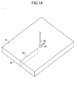
- Fig. 1A and Fig. 1B are views for explaining a method of cutting a strengthened glass plate of a first embodiment.
- Fig. 1B is a plan view of Fig. 1A .
- a strengthened glass plate 10 is cut by irradiating a laser beam 20 on a front surface (one of main surfaces) 12 of the strengthened glass plate 10 while moving an irradiation area 22 of the laser beam 20 on the front surface 12 of the strengthened glass plate 10 to apply stress on the strengthened glass plate 10.
- the strengthened glass plate 10 is manufactured by a thermally strengthening (or strengthening) method, a chemical strengthening (or strengthening) method or the like, for example.
- the kind of the strengthened glass is selected in accordance with its usage.
- a soda lime glass is used as the strengthened glass for a vehicle window glass, a structural window glass, a glass substrate for PDP or a cover glass.
- a non-alkali glass that does not substantially include alkali metal is used as the strengthened glass for a glass substrate for an LCD.
- a glass at a temperature near its softening point is quenched from a front surface and a back surface (both of main surfaces) so that a temperature difference between the front surface and the back surface (both of main surfaces) and the inside of the glass is generated to form the front surface layer and the back surface layer in which compression stresses remain, respectively.
- the thermally strengthening method is adaptable for strengthening a thick glass.
- a front surface and a back surface (both of main surfaces) of a glass are ion-exchanged to substitute ions (Li ions, Na ions, for example) each having a smaller ionic radius in the glass with ions (K ions, for example) each having a larger ionic radius to form the front surface layer and the back surface layer in which compression stresses remain, respectively.
- the chemical strengthening method is adaptable for strengthening a soda lime glass including alkali metal.
- an intermediate layer in which tensile stress is remained is formed between the front surface layer and the back surface layer as a counteraction of the formation of the front surface layer and the back surface layer in which compression stresses remain, respectively.
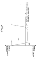
- Fig. 2A is a schematic view illustrating an example of distribution of a remaining stress in a chemically strengthened glass plate before irradiating a laser beam.
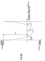
- Fig. 2B is a schematic view illustrating an example of a remaining stress in an thermally strengthened glass plate before irradiating a laser beam.
- Fig. 3 is a cross-sectional view illustrating an example of a strengthened glass plate before irradiating a laser beam.
- a direction of an arrow indicates an operation direction of stress, and the length of the arrow indicates the magnitude of the stress.
- the strengthened glass plate 10 includes a front surface layer 13 and a back surface layer 15, in which compression stresses remain, respectively, and an intermediate layer 17, in which a tensile stress remains, provided between the front surface layer 13 and the back surface layer 15.
- a surface layer of an end surface of the strengthened glass plate 10 may be composed only by a layer in which the compression stress remains, or may be composed by a layer in which the compression stress remains and a layer in which the tensile stress remains.
- the compression stresses (>0) remaining in the front surface layer 13 and the back surface layer 15 tend to gradually become smaller toward the inside from the front surface 12 and the back surface 14 of the strengthened glass plate 10, respectively.
- the tensile stress (>0) that remains in the intermediate layer 17 is almost constant.
- the thermally strengthened glass plate as shown in Fig. 2B , the tensile stress (>0) that remains in the intermediate layer 17 becomes gradually smaller from the inside of the glass toward the front surface 12 and the back surface 14 of the glass, respectively.
- CS indicates the maximum remaining compression stress (front surface compression stress) (>0) in the front surface layer 13 or the back surface layer 15
- CT indicates the internal remaining tensile stress (the average value of the remaining tensile stress of the intermediate layer 17) (>0) in the intermediate layer 17
- CM indicates the maximum remaining tensile stress in the intermediate layer 17
- DOL indicates the thickness of the front surface layer 13 or the back surface layer 15.
- CS indicates the maximum remaining compression stress (front surface compression stress) (>0) in the front surface layer 13 or the back surface layer 15
- CT indicates the internal remaining tensile stress (the average value of the remaining tensile stress of the intermediate layer 17) (>0) in the intermediate layer 17
- CM indicates the maximum remaining tensile stress in the intermediate layer 17
- DOL indicates the thickness of the front surface layer 13 or the back surface layer 15.
- CS indicates the maximum remaining compression stress (front surface compression stress) (>0) in the front surface layer 13 or the back surface layer 15
- CT indicates the internal remaining
- CS chemical strengthening method
- CT chemical strengthening method
- CM chemical strengthening method
- DOL chemical strengthening method
- concentration or temperature of process solution for example, KNO 3 fused-salt
- the front surface layer 13 and the back surface layer 15 of the embodiment have the same thickness and the same maximum remaining compression stress, they may have different thicknesses or different maximum remaining compression stresses.
- the front surface 12 of the strengthened glass plate 10 is not previously provided with scribe lines (groove lines) along proposed lines to be cut.
- the scribe lines may be previously formed, however, in such a case, the number of processes increases and operations become more complicated. Further, if the scribe lines are previously formed, the glass may be chipped.
- the strengthened glass plate 10 is previously provided with an initial crack at an end portion corresponding to a cut starting position.
- the initial crack may be formed by a general method such as using a cutter, a file or a laser.
- the initial crack may not be formed in order to reduce the number of process steps.
- the end portion of the strengthened glass plate 10 is previously grinded by a rotating grinder or the like before cutting, the initial crack may not be formed because a micro crack is formed when grinding the strengthened glass plate 10.
- the irradiation area 22 of the laser beam 20 (the center of the irradiation area 22 of the laser beam 20, for example) is moved on a straight line or a curved line along a proposed line to be cut from the end portion of the strengthened glass plate 10 toward the inside on the front surface 12 of the strengthened glass plate 10.
- a crack 30 (see Fig. 1A and Fig. 1B ) is formed from the end portion to the inside of the strengthened glass plate 10 and the strengthened glass plate 10 is cut.
- the irradiation area 22 of the laser beam 20 may be moved on a P-shaped line. In this case, a terminal end of the proposed line to be cut included in a moving path crosses the proposed line to be cut in the middle.
- a support member that supports the strengthened glass plate 10 may be moved or rotated or a light source of the laser beam 20 may be moved in order to move the irradiation area 22 of the laser beam 20 on the front surface 12 of the strengthened glass plate 10. Further, a mirror that is provided in the middle of a pathway of the laser beam 20 may be rotated.
- the irradiation area 22 of the laser beam 20 has a circular shape on the front surface 12 of the strengthened glass plate 10.
- the shape of the irradiation area 22 of the laser beam 20 is not particularly limited and alternatively, the irradiation area 22 of the laser beam 20 may have a rectangular shape, an elliptical shape or the like.
- the circularity of the irradiation area 22 may be less than or equal to 0.5R.
- the circularity is less than or equal to 0.5R, required accuracy in rotational control of the irradiation area 22 becomes lower when the center of the irradiation area 22 is moved along the proposed line to be cut having a curved shape on the front surface 12 of the strengthened glass plate 10. Further, when the accuracy in rotational control of the irradiation area 22 is almost the same, the cutting accuracy becomes higher as the variation in width of the irradiation area 22 in a direction of a normal line of the proposed line to be cut. For example, even when the radius of curvature of the proposed line to be cut is small, the glass can be accurately cut. More preferably, the circularity is less than or equal to 0.3R. Further more preferably, the circularity is less than or equal to 0.2R.
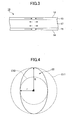
- the circularity is a difference between radiuses "R” and "r” of two concentric circles, which are a circumscribed circle C11 and an inscribed circle C12 of the irradiation area 22.
- R indicates the radius of the circumscribed circle C11 of the irradiation area 22
- r indicates the radius of the inscribed circle C12 of the irradiation area 22.
- the irradiation area 22 of the laser beam 20 is moved on the front surface 12 of the strengthened glass plate 10 at a speed in accordance with the thickness of the strengthened glass plate 10, the maximum remaining compression stress (CS), the internal remaining tensile stress (CT), the thickness of the front surface layer 13 or the back surface layer 15 (DOL), the power of the light source of the laser beam 20 or the like.
- CS maximum remaining compression stress
- CT internal remaining tensile stress
- DOL back surface layer 15
- the light source of the laser beam 20 is not specifically limited but may be, for example, an UV laser (wavelength: 355 nm), a green laser (wavelength: 532 nm), a diode laser (wavelength: 808 nm, 940 nm, 975 nm), a fiber-laser (wavelength: 1060 to 1100 nm), a YAG laser (wavelength: 1064 nm, 2080 nm, 2940 nm), a laser using a mid-infrared light parametric amplifier (wavelength: 2600 to 3450 nm) or the like.
- an UV laser wavelength: 355 nm
- a green laser wavelength: 532 nm
- a diode laser wavelength: 808 nm, 940 nm, 975 nm
- a fiber-laser wavelength: 1060 to 1100 nm
- a YAG laser wavelength: 1064 nm, 2080 nm, 2940
- the oscillating method of the laser beam 20 is not limited and both a CW laser which continuously oscillates the laser beam and a pulse laser which intermittently oscillates the laser beam may be used. Further, the intensity distribution of the laser beam 20 is not limited and may be a Gaussian shape or a top hat shape.
- the laser beam 20 irradiated from the light source is condensed by a condenser lens or the like and imaged onto the front surface 12 of the strengthened glass plate 10.
- a collection position of the laser beam 20 may be at a laser beam source side or a back surface 14 side when the front surface 12 of the strengthened glass plate 10 is taken as a reference. Further, as shown in Fig. 5 , the collection position of the laser beam 20 may be within the strengthened glass plate 10, specifically within the intermediate layer 17 as long as a condensing area does not become too high of a heating temperature, in other words, can be kept less than or equal to the annealing point.
- an area in which stress is generated by the laser beam 20 can be minimized so that cutting accuracy can be increased and the power of the light source of the laser beam 20 can be reduced as well.
- the laser beam 20 is absorbed as heat while passing through the strengthened glass plate 10 and the intensity is lowered.
- the difference between the heating temperature of the front surface 12 and the heating temperature of the back surface 14 becomes smaller as the intensity of the laser beam 20 per unit area (power density) in the back surface 14 becomes higher.
- the heating efficiency becomes better and the power of the light source of the laser beam 20 is reduced.
- An optical axis 21 of the laser beam 20 may be perpendicular to the front surface 12 as shown in Fig. 1A and Fig. 5 , for example (although the optical axis is not shown in Fig. 1A ) or may be oblique to the front surface 12 as shown in Fig. 6 , at the front surface 12 of the strengthened glass plate 10.
- the laser beam 20 that is reflected by the front surface 12 influences a laser oscillator
- the optical axis 21 of the laser beam 20 is oblique to the front surface 12, almost all of the reflected light does not return back to the laser oscillator and the influence can be reduced.
- the strengthened glass plate 10 cannot be cut as the laser beam 20 is absorbed by the film 18 and the front surface 12 is heated.
- the glass can be cut even when the proposed line to be cut overlaps an edge of the film 18.
- a ceramic film or a resin film may be used for improving the design and a transparent electrode film or the like may be used to improve the function.
- the glass is cut only by the function of the laser beam.
- a crack generated by the remaining tensile stress of the intermediate layer drastically propagates in an unintended direction so that the glass cannot be cut into a desired shape.
- the strengthened glass plate 10 is cut not only by the function of the laser beam 20 but also by using a propagation of a crack by the remaining tensile stress from the intermediate layer 17 when the strengthened glass plate 10 and the laser beam 20 satisfy an equation explained later. It means that, although the explanation is described later in detail, a propagation of the crack 30 generated in the strengthened glass plate 10 by the remaining tensile stress of the intermediate layer 17 is controlled by heating the intermediate layer 17 at the irradiation area 22 of the laser beam 20 at a temperature less than or equal to an annealing point by the above condition, so that the strengthened glass plate 10 can be cut by the crack 30 by the remaining tensile stress.
- the reason to heat the intermediate layer 17 at the temperature less than or equal to the annealing point is that, if the intermediate layer 17 is heated at a temperature higher than the annealing point, the glass becomes a higher temperature even within a short time in which the laser beam passes and a viscosity flow tends to be easily generated. Then, the compression stress generated by the laser beam is moderated by the viscosity flow.
- the strengthened glass plate 10 does not absorb too much of the laser beam by setting the moving speed of the irradiation area of the laser beam 20 as fast as possible.
- the moving speed of the irradiation area 22 of the laser beam 20 is set to be greater than or equal to 1.0 mm /sec to have 70.00% to 99.8% of the laser beam 20 injected into the front surface layer of the strengthened glass plate 10 transmitted.
- the amount of the laser beam 20 injected into the front surface 12 of the strengthened glass plate 10 is less than the amount of the laser beam 20 output from the light source for an amount reflected or diffused by the front surface 12 of the strengthened glass plate 10.
- the transmittance of the laser beam 20 with respect to the strengthened glass plate 10 can be measured by a method of measuring defined by JIS R3106 and is normalized after removing the reflected light. It means that, among the laser beam 20 output from the light source, a ratio of the transmitted light with respect to a total of the absorbed light absorbed by the strengthened glass plate 10 and the transmitted light transmitted the strengthened glass plate 10 is defined as a transmittance.
- the moving speed of the irradiation area 22 of the laser beam 20 may be different or the same in accordance with cutting positions of the strengthened glass plate 10.
- the strengthened glass plate 10 will have edge portions and corner portions of the rectangular.
- the irradiation area 22 may be moved at a lower speed at the corner portions and moved at a higher speed at the edge portions. Even when the irradiation area 22 is moved at the lower speed, the speed is greater than or equal to 1.0 mm / sec.
- the rectangular shape here is not necessarily a strict rectangular and may include a convex portion or a concave portion at a part of the rectangular, or the corner portion may have a predetermined curved shape.
- This equation is a so-called Lambert-Beer law.
- ⁇ expresses an absorption coefficient (cm -1 ) of the strengthened glass plate 10 with respect to the laser beam 20.
- the laser beam 20 When the laser beam 20 is perpendicularly injected into the front surface 12 of the strengthened glass plate 10, the laser beam 20 moves a distance that is the same as the thickness t (cm) of the strengthened glass plate 10 and is ejected from the back surface 14. At this time, the laser beam 20 can reach the inside without being absorbed at the front surface of the strengthened glass plate 10 when the strengthened glass plate 10 and the laser beam 20 satisfy an equation 0 ⁇ ⁇ ⁇ t ⁇ 3.0. Then, the inside of the strengthened glass plate 10 is sufficiently heated and the stress generated in the strengthened glass plate 10 is changed from a status shown in Fig. 3 to a status shown in Fig. 7 or Fig. 8 .
- Fig. 7 is a schematic view illustrating an example of distribution of stress along an A-A line in Fig. 1B , and is a schematic view illustrating an example of the distribution of the stress in a cross-section including the irradiation area of the laser beam.
- Fig. 8 is a schematic view illustrating an example of distribution stress along a B-B line in Fig. 1B , and is a schematic view illustrating an example of the distribution of the stress at a cross-section at a back side of the cross-section shown in Fig. 7 .
- the "back side" means a back side of the scanning direction of the laser beam 20.
- a direction of an arrow indicates an operation direction of stress, and the length of the arrow indicates the magnitude of the stress.
- the temperature becomes higher compared with the circumference.
- the tensile stress smaller than the remaining tensile stress shown in Fig. 2A , Fig. 2B and Fig. 3 or the compression stress is generated.
- the propagation of the crack 30 is suppressed. In order to surely prevent the propagation of the crack 30, as shown in Fig. 7 , it is preferable that the compression stress is generated.
- the tensile stress is generated in the intermediate layer 17 in the cross-section at the back side of the cross-section shown in Fig. 7 as shown in Fig. 8 .
- the tensile stress is larger than the remaining tensile stress and a crack 30 is generated at a portion at which the tensile stress reaches a predetermined value.
- the crack 30 is formed to penetrate the front surface 12 to the back surface 14 of the strengthened glass plate 10. In this embodiment, the cut is a so-called "full cut".
- the crack 30 is not automatically formed shifting from the proposed line to be cut and a front end position of the crack 30 moves to follow the position of the irradiation area 22.
- the propagation of the crack 30 can be controlled by the laser beam 20.
- the propagation of the crack 30 can be controlled by the laser beam 20 in the strengthened glass plate 10. Then, as the crack 30 propagates right after the irradiation area 22, the cutting line is generated exactly the same as the moving trail of the irradiation area 22 and the cutting accuracy can be improved.
- a front end of the crack 30 may not follow right after the irradiation area 22 but may follow the irradiation area 22 in an overlapped manner. The cutting accuracy can be improved as the front end of the crack 30 is closer to the irradiation area 22 or the front end of the crack 30 overlaps the irradiation area 22.
- ⁇ ⁇ t is greater than or equal to 0.0005 (the laser beam absorption ratio is greater than or equal to 0.05%), more preferably, greater than or equal to 0.002 (the laser beam absorption ratio is greater than or equal to 0.2%), and further more preferably, greater than or equal to 0.004 (the laser beam absorption ratio is greater than or equal to 0.4%).
- ⁇ ⁇ t is less than or equal to 3.0 (the laser beam absorption ratio is less than or equal to 95%), more preferably, less than or equal to 0.105 (the laser beam absorption ratio is less than or equal to 10%), and further more preferably, less than or equal to 0.02 (the laser beam absorption ratio is less than or equal to 2%).
- CT internal remaining tensile stress
- the remaining tensile stress of the intermediate layer 17 may be greater than or equal to 15 MPa so that the internal remaining tensile stress (CT) dominants the tensile stress generated by the laser beam 20 among the tensile stress used for cutting the glass.
- CT remaining tensile stress
- the distance between a position at which the tensile stress reaches the predetermined value (in other words, a position of the front end of the crack 30) and the position of the laser beam 20 becomes sufficiently short in the strengthened glass plate 10 so that the cutting accuracy is improved.
- the internal remaining tensile stress (CT) of the intermediate layer 17 may be greater than or equal to 30 MPa and more preferably, greater than or equal to 40 MPa. When the internal remaining tensile stress (CT) is greater than or equal to 30 MPa, the remaining tensile stress of the intermediate layer 17 is only the tensile stress that is used for cutting the glass so that the accuracy in tracking of the cutting line can be further improved.
- the upper limited value of the internal remaining tensile stress (CT) is 120 MPa.
- CT internal remaining tensile stress
- the glass can be strengthened as high as about 120 MPa due to a technical reason in a strengthening process.
- the present invention can be applied to such a chemically strengthened glass.
- the absorption coefficient ( ⁇ ) is defined by the wavelength of the laser beam 20, the glass composition of the strengthened glass plate 10 or the like.
- the contents of copper oxide (including CuO or Cu 2 O) in the strengthened glass plate 10 increase, the absorption coefficient ( ⁇ ) in a near infrared wavelength area near 1000 nm becomes greater.
- the absorption coefficient ( ⁇ ) near an absorbed wavelength of the rare earth becomes greater.
- the absorption coefficient ( ⁇ ) in a near infrared wavelength area near 1000 nm is set in accordance with its usage.
- the absorption coefficient ( ⁇ ) may be less than or equal to 3 cm -1 .
- the absorption coefficient ( ⁇ ) may be less than or equal to 0.6 cm -1 .
- the absorption coefficient ( ⁇ ) may be less than or equal to 0.2 cm -1 .
- the wavelength of the laser beam 20 may be 250 to 5000 nm. By setting the wavelength of the laser beam 20 to 250 to 5000 nm, both of the transmittance of the laser beam 20 and the heating efficiency of the laser beam 20 are compatible.
- the wavelength of the laser beam 20 is preferably 300 to 4000 nm, and is more preferably 800 to 3000 nm.
- the contents of iron oxide in the strengthened glass plate 10 are, for example, 0.02 to 1.0 mass % although that depend on the kind of the glass that constitute the strengthened glass plate 10.
- the value of ⁇ ⁇ t is adjustable to a desired range by adjusting the contents of iron oxide within this range using a generalized near infrared laser near 1000 nm. Instead of adjusting the contents of iron oxide, the contents of the oxide of cobalt oxide, copper oxide or a rare earth element may be adjusted.
- the thickness (t) of the strengthened glass plate 10 is determined in accordance with its usage.
- the thickness (t) of the strengthened glass plate 10 may be 0.01 to 0.2 cm.
- the internal remaining tensile stress (CT) can be sufficiently increased by setting the thickness (t) to less than or equal to 0.2 cm.
- CT internal remaining tensile stress
- the thickness (t) is less than 0.01 cm, it is difficult to perform a chemical strengthening process on the glass. More preferably, the thickness (t) may be 0.03 to 0.15 cm, and further more preferably 0.05 to 0.15 cm.
- the thickness (t) of the strengthened glass plate 10 may be 0.1 to 3 cm.
- the internal remaining tensile stress (CT) can be sufficiently increased by setting the thickness (t) to less than or equal to 3 cm.
- CT tensile stress
- the thickness (t) becomes less than 0.1 cm, it is difficult to apply a thermally strengthening process on the glass.
- the thickness (t) is preferably 0.15 to 2 cm, and more preferably 0.2 to 1.5 cm.
- the irradiation area 22 of the laser beam 20 may have a diameter ( ⁇ ) greater than 0.18 mm and less than the thickness of the strengthened glass plate 10 at the front surface (a surface into which the laser beam 20 is injected) 12 of the strengthened glass plate 10.
- the diameter ( ⁇ ) becomes greater than or equal to the thickness of the strengthened glass plate 10
- the irradiation area 22 of the laser beam 20 and the heated area become too large so that a part of the cut surface (in particular, a cut starting portion or a cut terminal portion) may be slightly curved.
- the diameter ( ⁇ ) may be less than 1.03 mm.
- the diameter ( ⁇ ) may be less than or equal to 0.5 mm so that the cutting accuracy is improved as the positional controllability of the crack 30 is increased.
- the diameter ( ⁇ ) is less than or equal to 0.18 mm, the power density becomes too high when a variation in power control of the laser beam 20 is generated so that the cut surface becomes rough and there may be a case that a fine fissure is formed.
- the value of ⁇ ⁇ t is as small as less than or equal to 0.105 (the laser beam absorption ratio is less than or equal to 10%), even when the power density becomes high due to the variation in the power control, the influence is hardly applied.
- Fig. 9 is a view for explaining a method of cutting a strengthened glass plate of a second embodiment.
- the same components are given the same reference numerals as those in Fig. 1A and explanations are not repeated.
- the strengthened glass plate 10 is cut by irradiating the laser beam 20 on the front surface 12 of the strengthened glass plate 10 while moving the irradiation area 22 of the laser beam 20 on the front surface 12 of the strengthened glass plate 10.
- the strengthened glass plate 10 is cut using a propagation of a crack by the remaining tensile stress of the intermediate layer 17 by having the strengthened glass plate 10 and the laser beam 20 satisfy an equation 0 ⁇ ⁇ ⁇ t ⁇ 3.0, where the absorption coefficient of the strengthened glass plate 10 with respect to the laser beam 20 is ⁇ (cm -1 ) and the thickness of the strengthened glass plate 10 is t (cm). It means that it is possible to control the propagation of the crack 30 generated in the strengthened glass plate 10 by the remaining tensile stress of the intermediate layer 17 by heating the intermediate layer 17 at a temperature less than or equal to the annealing point at the irradiation area 22 of the laser beam 20.
- the same advantages as the first embodiment can be obtained.
- a gas 40 is sprayed on the front surface 12 of the strengthened glass plate 10 and a spraying area 42 of the gas 40 is moved on the front surface 12 of the strengthened glass plate 10 in association with the irradiation area 22 of the laser beam 20 (with the irradiation area 22).
- the spraying area 42 may overlap the irradiation area 22 or be provided in the vicinity of the irradiation area 22. Further, the spraying area 42 may antecede the irradiation area 22 or may follow the irradiation area 22.
- compressed air or the like is used, for example.
- Deposits (dust, for example) adhered to the front surface 12 of the strengthened glass plate 10 is sprayed by the compressed air to prevent adsorption of the laser beam 20 by the deposits. Thus, overheating of the front surface 12 of the strengthened glass plate 10 can be prevented.
- the gas 40 may be a coolant gas that locally cools the strengthened glass plate 10.
- the spraying area 42 of the gas 40 may follow the irradiation area 22 such that the spraying area 42 of the gas 40 is positioned in the vicinity of a back side in a moving direction of the irradiation area 22 of the laser beam 20.
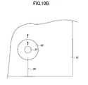
- Fig. 10A and Fig. 10B are views for explaining a method of cutting a strengthened glass plate of a third embodiment.
- Fig. 10A is a cross-sectional view illustrating a cross-section of a strengthened glass plate
- Fig. 10B is a plan view illustrating the front surface of the strengthened glass plate in an enlarged manner.
- a direction of an arrow indicates a direction of a flow of gas.
- Fig. 10A and Fig. 10B the same components are given the same reference numerals as those in Fig. 1A , Fig. 9 or the like and explanations are not repeated.
- the irradiation area 22 of the laser beam 20 is positioned inside the outer edge of the spraying area 42 in this embodiment, where the spraying area 42 of the gas 40 is provided in the vicinity of the back side of the irradiation area 22 of the laser beam 20 in the second embodiment.
- Other structures are the same as those of the second embodiment and the difference is mainly explained.
- the gas 40 is a coolant gas that locally cools the strengthened glass plate 10.
- the irradiation area 22 of the laser beam 20 is provided at an inner side of an outer edge of the spraying area 42 of the gas 40.
- the spraying area 42 of the gas 40 is an area on the front surface 12 of the strengthened glass plate 10 to which the exit 52 of the nozzle 50, which is an ejection port of the gas 40, is projected in a direction parallel to a center axis 51 of the nozzle 50.
- the heating area of the strengthened glass plate 10 can be contracted.
- the distance between a position at which the tensile stress reaches the predetermined value in other words, a position of the front end of the crack 30
- the cutting accuracy can be further improved.
- the nozzle 50 is formed into a tubular shape, as shown in Fig. 10A , for example, and the laser beam 20 may pass inside the nozzle 50.
- the center axis 51 of the nozzle 50 and the optical axis 21 of the laser beam 20 may be coaxially positioned. This is effective for a case where the positional relationship is unnecessary to be changed as the positional relationship between the spraying area 42 of the gas 40 and the irradiation area 22 of the laser beam 20 is fixed.
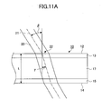
- Fig. 11A and Fig. 11B are views for explaining a method of cutting a strengthened glass plate of a fourth embodiment.
- Fig. 11A is a cross-sectional view taken along an A-A line in Fig. 11B.
- Fig. 11B is a plan view of the strengthened glass plate.
- the same components are given the same reference numerals as those in Fig. 1A or the like and explanations are not repeated.
- the laser beam 20 is perpendicularly injected into the front surface 12 of the strengthened glass plate 10.
- the laser beam 20 is obliquely injected into the front surface 12 of the strengthened glass plate 10.
- Other structures are the same as those of the second embodiment and the difference is mainly explained.
- the strengthened glass plate 10 can be separated in the thickness direction by cut portions obtained by cutting the strengthened glass.
- the inclination of the cut surface of the strengthened glass plate 10 with respect to the thickness direction becomes large. As this inclination becomes larger, it becomes easier for the strengthened glass plate 10 to be separated in the thickness direction after cutting, however, a chamfering process for the cut surface after cutting becomes difficult.
- the angle-of-incidence ⁇ is set in accordance with a positional relationship between the optical axis 21 of the laser beam 20 and the proposed line to be cut 11 of the front surface 12 of the strengthened glass plate 10.
- the angle-of-incidence ⁇ is set to be within a range of 1° to 60° when seen in a plan view (in the thickness direction).
- the optical axis 21 of the laser beam 20 may be obliquely positioned with respect to the proposed line to be cut 11 when seen in a plan view (in the thickness direction).
- the laser beam 20 When the laser beam 20 is obliquely injected into the front surface 12 of the strengthened glass plate 10, the laser beam 20 moves a distance t / cos ⁇ and is ejected from the back surface 14. At this time, the laser beam 20 can reach the inside without being absorbed in the vicinity of the front surface 12 of the strengthened glass plate 10 when the strengthened glass plate 10 and the laser beam 20 satisfy an equation 0 ⁇ ⁇ ⁇ t / cos ⁇ ⁇ 3.0.
- the propagation of the crack 30 generated in the strengthened glass plate 10 can be controlled by the remaining tensile stress of the intermediate layer 17.
- the same advantages as the first embodiment can be obtained.
- the gas 40 may be sprayed on the front surface 12 of the strengthened glass plate 10 and the spraying area 42 of the gas 40 may be cooperatively moved with the irradiation area 22 of the laser beam 20 on the front surface 12 of the strengthened glass plate 10.
- the spraying area 42 of the gas 40 may overlap the irradiation area 22 of the laser beam 20, or may be provided in the vicinity of the irradiation area 22 of the laser beam 20. Further, the irradiation area 22 of the laser beam 20 may be provided at the inner side of the outer edge of the spraying area 42.
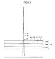
- Fig. 12 is a view for explaining a method of cutting a strengthened glass plate of a fifth embodiment.
- the same components are given the same reference numerals as those in Fig. 1A and explanations are not repeated.
- a plurality of (three, for example) strengthened glass plates 10A to 10C in a stacked manner are cut at the same time.
- ⁇ ⁇ t is as small as less than or equal to 0.105 (the laser beam absorption ratio is less than or equal to 10%)
- almost all of the laser beam irradiated on the front surface of the strengthened glass plate 10 is transmitted so that it is possible to cut the plurality of strengthened glass plates 10 in the stacked manner at the same time.
- the other structures are similar to those of the second embodiment, the difference is mainly explained.
- the laser beam 20 is irradiated on a front surface (one of main surfaces) 112 of a stacked body 110, which is composed by N (N is a natural number greater than or equal to 2) stacked strengthened glass plates 10A to 10C and the irradiation area 22 of the laser beam 20 is moved on each of the front surfaces 12A to 12C of the strengthened glass plates 10A to 10C, respectively, to cut the N strengthened glass plates 10A to 10C.
- the N strengthened glass plates 10A to 10C may have different glass compositions from each other, preferably, the N strengthened glass plates 10A to 10C may have the same glass composition. Although the N strengthened glass plates 10A to 10C may have different thicknesses from each other, preferably, the N strengthened glass plates 10A to 10C may have the same thickness. Although the N strengthened glass plates 10A to 10C may have different coefficients of thermal expansion from each other, preferably, the N strengthened glass plates 10A to 10C may have the same coefficients of thermal expansion. Although the N strengthened glass plates 10A to 10C may have different absorption coefficients ⁇ from each other, preferably, the N strengthened glass plates 10A to 10C have the same absorption coefficient ⁇ .
- the strengthened glass plates adjacent to each other may be in contact with each other or may be apart from each other. Further, in the stacked body 110, a spacer such as resin or the like may be provided between the strengthened glass plates adjacent to each other (the strengthened glass plate 10A and the strengthened glass plate 10B, for example).
- the laser beam 20 may be perpendicularly injected into a front surface (an upper surface in Fig. 12 ) 112 of the stacked body 110. It means that the laser beam 20 may be perpendicularly injected into each of the front surfaces 12A to 12C the strengthened glass plates 10A to 10C, respectively.
- Each of the strengthened glass plates 10A to 10C and the laser beam 20 satisfy an equation 0 ⁇ ⁇ i ⁇ t i ⁇ 3.0 (where i is an arbitrary natural number greater than or equal to 1 and less than or equal to N), where the absorption coefficient of each of the strengthened glass plates 10 with respect to the laser beam 20 is ⁇ i (cm -1 ) and the thickness of each of the strengthened glass plates 10 is t i (cm).
- the laser beam 20 When the laser beam 20 is perpendicularly injected into each of the front surfaces 12A to 12C of the strengthened glass plates 10A to 10C, respectively, the laser beam 20 moves a distance the same as the thickness t i (cm) of each of the strengthened glass plates 10A to 10C and is ejected from the back surface. At this time, the laser beam 20 can reach the inside without being absorbed in the vicinity of each of the front surfaces 12A to 12C of the strengthened glass plates 10A to 10C, respectively, when each of the strengthened glass plates 10A to 10C and the laser beam 20 satisfy an equation 0 ⁇ ⁇ i ⁇ t i ⁇ 3.0.
- the propagation of the crack generated in each of the strengthened glass plates 10A to 10C can be controlled by the remaining tensile stress of the intermediate layer of each of the strengthened glass plates 10A to 10C.
- the same advantage as the first embodiment can be obtained.
- the gas 40 may be sprayed on the front surface 112 of the stacked body 110 and the spraying area 42 of the gas 40 may be moved in association with the irradiation area 22 of the laser beam 20 on the front surface 112 of the stacked body 110.
- the spraying area 42 of the gas 40 may overlap the irradiation area 22 of the laser beam 20 or may be provided in the vicinity of the irradiation area 22 of the laser beam 20. Further, the irradiation area 22 of the laser beam 20 may be provided at the inner side of the outer edge of the spraying area 42.
- the laser beam 20 is perpendicularly injected into each of the front surfaces 12A to 12C of the strengthened glass plates 10A to 10C, respectively, similar to the fourth embodiment, the laser beam 20 may be obliquely injected into each of the front surfaces 12A to 12C of the strengthened glass plates 10A to 10C, respectively.
- each of the strengthened glass plates 10 and the laser beam 20 satisfy an equation 0 ⁇ ⁇ i ⁇ t i / cos ⁇ i ⁇ 3.0 (i is an arbitrary natural number greater than or equal to 1 and less than or equal to N), where the angle of refraction of the laser beam 20 at each of the front surfaces 12A to 12C of the strengthened glass plates 10A to 10C, respectively, is ⁇ i .
- a glass plate of 50 mm x50 mm with a predetermined thickness was manufactured as a glass plate for a chemical strengthening method by dissolving a glass material prepared by mixing a plurality of kinds of materials, shaping the dissolved molten glass into a plate shape to be gradually cooled to near room temperature, cutting, machining, and mirror finishing both surfaces.
- the glass material was prepared by varying loadings of powders of iron oxide (Fe 2 O 3 ) with respect to a base material having the same proportioning ratio so that the absorption coefficient ( ⁇ ) of the glass plate with respect to the laser beam became a desired value.
- the respective glass plate for a chemical strengthening method includes SiO 2 : 60.7%, Al 2 O 3 : 9.6%, MgO: 7.0%, CaO: 0.1%, SrO: 0.1%, BaO: 0.1%, Na 2 O: 11.6%, K 2 O: 6.0% and ZrO 2 : 4.8%, mass % as calculated as oxide, and a predetermined amount (a predetermined outer percentage) of iron oxide (Fe 2 O 3 ).
- the respective chemically strengthened glass plate was manufactured by soaking the respective glass plate for a chemical strengthening method in KNO 3 fused-salt to perform an ion-exchange and then cooling to near room temperature.
- the process conditions such as the temperature or soaking period of KNO 3 fused-salt or the like were set such that the internal remaining tensile stress (CT) became a desired value.
- CT The internal remaining tensile stress (CT) of the respective chemically strengthened glass plate was obtained by measuring a front surface compression stress (CS) and a depth of a compression stress layer (DOL) using a front surface stress measuring device FSM-6000 (manufactured by Orihara Manufacturing Co., LTD.) and calculating using the following equation (I) based on the measured values and the thickness (t) of the chemically strengthened glass plate.
- CT CS ⁇ DOL / t - 2 ⁇ DOL
- the front surface layer and the back surface layer of each of the chemically strengthened glass plates had the same thickness and the same maximum compression stress.
- CT C ⁇ 1 ⁇ D ⁇ 1 / 2 + C ⁇ 2 ⁇ D ⁇ 2 / 2 / t - D ⁇ 1 - D ⁇ 2
- the chemically strengthened glass plate was cut by a cutting method shown in Fig. 1A and Fig. 1B .
- An initial crack was previously formed at a cut starting position at a side surface of the respective chemically strengthened glass plate by a file but scribe lines were not formed at the front surface of the respective chemically strengthened glass plate.
- the light source of the laser beam was a fiber-laser (center wavelength range: 1075 to 1095 nm).
- the absorption coefficient of each of the chemically strengthened glass plates with respect to the laser beam was measured by a UV-visible near-infrared spectrophotometer Lambda 950.
- the optical axis of the laser beam was positioned to be perpendicular to each of the front surfaces of the chemically strengthened glass plates, respectively.
- the irradiation area of the laser beam was moved at a constant speed of 10 mm /sec for 50 mm from one end (initial crack) to the other end of a proposed line to be cut on a front surface of each of the chemically strengthened glass plates.
- the proposed line to be cut which is the center line of the moving path, was a straight line parallel to one of the edges of the rectangular shape chemically strengthened glass plate, where the distance from the edge was 10 mm.
- the irradiation area of the laser beam had a circular shape.
- the collection position of the laser beam was provided at a position -10.3 to 20 mm from the front surface of each of the chemically strengthened glass plates (upper surface) (the upward direction is determined as positive where the upper surface is the standard (the light source side)).
- the collection angle of the laser beam was set to be 1.4 to 33.4°.
- Cut results were evaluated by (1) whether being cut, (2) a quality of a cut end portion, (3) a quality of a cut surface and (4) the maximum shifted amount.
- the glass can be used depending on its usage.
- Example 1-1 to Example 1-4 shown in Table 1 For each of Example 1-1 to Example 1-4 shown in Table 1, at any cases, evaluations of whether being cut, the quality of the cut end portion and the quality of the cut surface were all " ⁇ " and the maximum shifted amount was 0 mm.
- Example 1-5 to Example 1-10 different from Example 1-1 to Example 1-4 (examples), the chemically strengthened glass plate was attempted to be cut while the value of the thickness (t) ⁇ absorption coefficient ( ⁇ ) was set to be greater than 3.0.
- Example 1-5 a chemically strengthened glass plate was manufactured similarly to Example 1-4 except that the thickness (t) was changed. Then, the irradiation area of the laser beam was moved on the manufactured chemically strengthened glass plate.
- Example 1-6 to Example 1-10 a chemically strengthened glass plate was manufactured similarly to Example 1-2 except that a carbon dioxide gas laser (wavelength: 10600 nm) was used as the light source of the laser beam and the absorption coefficient ( ⁇ ) was changed (the thickness (t) was also changed for Example 1-6 to Example 1-8). Then, the irradiation area of the laser beam was moved on the manufactured chemically strengthened glass plate.
- the irradiation area of the laser beam at the front surface of the chemically strengthened glass plate was set to be an elliptical shape (length 12 mm, width 3 mm) longer in a moving direction in order to retain a heat transmission period by propagating the irradiation period of the laser beam.
- Example 2-1 to Example 2-20 the internal remaining tensile stress (CT) was adjusted by changing chemically strengthening process conditions and the relationship between the internal remaining tensile stress (CT) and the maximum shifted amount was examined.
- Manufacturing of, cutting of and the evaluation of the evaluating chemically strengthened glass plate were performed similarly to Example 1-1 to Example 1-4.
- the evaluated results are shown in Table 3 to Table 5 with cutting conditions and the like.
- Example 3-1 to Example 3-8 the cut results were evaluated by changing the size and shape of the irradiation area of the laser beam at the front surface of the chemically strengthened glass plate. Manufacturing of, cutting of and the evaluation of the evaluating chemically strengthened glass plate were performed similarly to Example 1-1 to Example 1-4.
- the quality of the cut end portion or the quality of the cut surface is good when the irradiation area of the laser beam is formed to be a circular shape at the front surface of the chemically strengthened glass plate and the diameter ( ⁇ ) is greater than 0.18 mm and less than the thickness (1.0 mm) of the chemically strengthened glass plate.
- the diameter ( ⁇ ) is 0.18 mm, there was a fine fissure at the cut surface.
- the diameter ( ⁇ ) is 1.03 mm, the cut end portion of the cut surface was slightly curved.
- Example 4-1 to Example 4-4 the relationship between the maximum laser scanning speed at which the chemically strengthened glass plate is capable of being cut along the proposed line to be cut (without occurrence of automatic formation of a crack or breaking of the glass), and the diameter of the laser beam at the front surface of the chemically strengthened glass plate was examined.
- the respective chemically strengthened glass plate includes SiO 2 : 61.0%, Al 2 O 3 : 12.8%, MgO: 6.6%, CaO: 0.1%, SrO: 0.2%, BaO: 0.2%, Na 2 O: 12.2%, K 2 O: 5.9% and ZrO 2 : 1.0%, mass % as calculated as oxide.
- the front surface compression stress (CS) of each of the chemically strengthened glass plates was 735 MPa, the depth of the compression stress layer (DOL) was 51.2 ( ⁇ m) and the internal tensile stress (CT) was 38 (MPa).
- the chemically strengthened glass plate (300 mm ⁇ 300 mm ⁇ 1.1 mm) was cut by a cutting method shown in Fig. 10A and Fig. 10B .
- An initial crack was previously formed at a cut starting position at a side surface of the respective chemically strengthened glass plate by a file but scribe lines were not formed at the front surface of the respective chemically strengthened glass plate.
- An exit of a nozzle was formed to have a circular shape having a diameter of 2 mm and positioned at a position such that a gap G (see Fig. 10A ) between the front surface of the respective chemically strengthened glass plate was 3 mm.
- the compressed air at room temperature was ejected toward the front surface of the respective chemically strengthened glass plate from the exit of the nozzle at a flow rate of 100 L / min.
- the center axis of the nozzle and the optical axis of the laser beam were coaxially provided to be perpendicular to the front surface of the respective chemically strengthened glass plate.
- a fiber-laser (center wavelength: 1070 nm) was used.
- the absorption coefficient of the respective chemically strengthened glass plate with respect to the laser beam was measured using a UV-visible near-infrared spectrophotometer Lambda 950.
- the collection position of the laser beam was provided at a position 0 to 2.8 mm above (an opposite side of the back surface) from the front surface of the respective chemically strengthened glass plate.
- the collection angle of the laser beam was 4°.
- the center of the laser beam was moved from one end to the other end of the proposed line to be cut for 300 mm at a plane the same as the front surface of the respective chemically strengthened glass plate.
- the proposed line to be cut which is the moving path, was a straight line parallel to one of the edges (shorter edge) of the rectangular shape chemically strengthened glass plate, where the distance from the edge was 10 mm.
- the center of the laser beam was moved from a cut starting end of the proposed line to be cut for 15 mm at a speed of 2.5 mm /sec while setting the diameter of the laser beam to be 0.2 mm, and subsequently, the diameter of the laser beam was changed to the diameter as shown in Table 7 while moving the center of the laser beam for a further 5 mm, at a plane the same as the front surface of the respective chemically strengthened glass plate. Thereafter, the moving speed of the laser beam was accelerated to a targeted speed and maintained at the targeted speed. The maximum speed at which the glass was cut is shown in Table 7.
- EXAMPLE 4-1 EXAMPLE 4-2 EXAMPLE 4-3 EXAMPLE 4-4 LASER BEAM LIGHT SOURCE POWER (W) 120 120 120 120 COLLECTION ANGLE (° ) 4 4 4 COLLECTION POSITION (mm) 0 0.7 1.4 2.8 ⁇ (mm) 0.02 0.05 0.1 0.2 TEMPERED GLASS CT(MPa) 38 38 38 38 t(cm) 0.11 0.11 0.11 0.11 ⁇ (/cm) 0.09 0.09 0.09 0.09 ⁇ (/cm) ⁇ t (cm) 0.010 0.010 0.010 0.010 RATIO OF TRANSMITTED LIGHT (%) 99.01 99.01 99.01 99.01 99.01 MAXIMUM SPEED CAPABLE OF CUTTING GLASS (mm/s) 60 60 50 30
- the scanning speed of the laser beam can be improved as the diameter of the laser beam becomes smaller when the light source power is constant.
- the power density (W / mm 2 ) of the laser beam is increased so that the heating period can be shortened.
- Example 5-1 to Example 5-2 the relationship between the minimum light source power capable of cutting the chemically strengthened glass plate at the proposed line to be cut (without occurrence of automatic formation of a crack or breaking of the glass) and whether the nozzle is used was examined.
- the respective chemically strengthened glass plate (150 mm x100 mm ⁇ 1.1 mm) was cut by the method shown in Fig. 10A and Fig. 10B .
- An initial crack was previously formed at a cut starting position at a side surface of the respective chemically strengthened glass plate by a file but scribe lines were not formed at the front surface of the chemically strengthened glass plate.
- a fiber-laser (center wavelength: 1070 nm) was used.
- the absorption coefficient of the respective chemically strengthened glass plate with respect to the laser beam was measured using a UV-visible near-infrared spectrophotometer Lambda 950.
- the collection position of the laser beam was provided at a position 0 mm above (an opposite side of the back surface) from the front surface of the respective chemically strengthened glass plate.
- the collection angle of the laser beam was 8.9°.
- the center of the laser beam was moved from one end to the other end of the proposed line to be cut for 150 mm at a plane the same as the front surface of the respective chemically strengthened glass plate.
- the proposed line to be cut which is the moving path, was a straight line parallel to one of the edges (shorter edge) of the rectangular shape chemically strengthened glass plate, where the distance from the edge was 10 mm.
- the irradiation area of the laser beam was moved from a cut starting end of the proposed line to be cut for 15 mm at a speed of 2.5 mm /sec while setting the diameter of the laser beam to be 0.2 mm, and subsequently, the diameter of the laser beam was reduced from 0.2 mm to 0.1 mm while moving the center of the laser beam for a further 5 mm, at a plane the same as the front surface of the respective chemically strengthened glass plate. Thereafter, the moving speed of the laser beam was accelerated to a targeted speed (10 mm /sec) and maintained at the targeted speed. The reason that the moving speed was slowed at start of cutting is that it takes time to form the crack.
- Example 5-1 the nozzle was not used, in Example 5-2, the nozzle was used and the coolant gas was sprayed on the front surface of the chemically strengthened glass plate.
- the center axis of the nozzle was coaxially provided with the optical axis of the laser beam such to be perpendicular to the front surface of the respective chemically strengthened glass plate.
- An exit of the nozzle was formed to have a circular shape having a diameter of 1 mm and is positioned at a position such that a gap G (see Fig. 10A ) between the front surface of the respectively chemically strengthened glass plate was 2 mm.
- Compressed air at room temperature was ejected toward the front surface of the respective chemically strengthened glass plate from the exit of the nozzle at a flow rate of 15 L / min.
- the light source power can be reduced by using the nozzle ejecting the coolant gas.
- Example 6-1 to Example 6-5 the relationship between the minimum light source power at which the chemically strengthened glass plate is cut along the proposed line to be cut (without occurrence of automatic formation of a crack or breaking of the glass), and the collection position of the laser beam was examined.
- the respective chemically strengthened glass plate (150 mm x100 mm ⁇ 1.1 mm) was cut by the cutting method shown in Fig. 10A and Fig. 10B .
- An initial crack was previously formed at a cut starting position at a side surface of the respective chemically strengthened glass plate by a file but scribe lines were not formed at the front surface of each of the chemically strengthened glass plates.
- a fiber-laser (center wavelength: 1070 nm) was used.
- the absorption coefficient of the respective chemically strengthened glass plate with respect to the laser beam was measured using a UV-visible near-infrared spectrophotometer Lambda 950.
- the center of the laser beam was moved from one end to the other end of the proposed line to be cut for 150 mm at a plane the same as the front surface of the chemically strengthened glass plate.
- the proposed line to be cut which is the moving path, was a straight line parallel to one of the edges (shorter edge) of the rectangular shape chemically strengthened glass plate, where the distance from the edge was 10 mm.
- the diameter of the laser beam was moved from a cut starting end of the proposed line to be cut for 15 mm at a speed of 2.5 mm /sec while setting the diameter of the laser beam to be 0.2 mm, and subsequently, the diameter of the laser beam was reduced from 0.2 mm to 0.1 mm while moving the center of the laser beam for a further 5 mm, at a plane the same as the front surface of the respective chemically strengthened glass plate. Thereafter, the moving speed of the laser beam was accelerated to a targeted speed (10 mm /sec) and maintained at the targeted speed. The reason that the moving speed was slowed at start of cutting is that it takes time to form the crack.
- the collection position of the laser beam was set to be a position 1.3 mm above the front surface of the chemically strengthened glass plate (an opposite side of the back surface) when the moving speed of the laser beam was low.
- the collection position of the laser beam was changed before the moving speed of the laser beam was changed from low to high.
- the collection position of the laser beam after the change was, 0.4 mm above the front surface of the chemically strengthened glass plate for Example 6-1, at the front surface of the chemically strengthened glass plate for Example 6-2, at the center position of the chemically strengthened glass plate in the thickness direction for Example 6-3, at the back surface of the chemically strengthened glass plate for Example 6-4, and 0.4 mm below the back surface of the chemically strengthened glass plate for Example 6-5.
- the center axis of the nozzle was coaxially provided with the optical axis of the laser beam such that to be perpendicular to the front surface of the respective chemically strengthened glass plate.
- An exit of the nozzle was formed to have a circular shape having a diameter of 1 mm and positioned at a position such that a gap G (see Fig. 10A ) between the front surface of the respective chemically strengthened glass plate was 2 mm.
- Compressed air at room temperature was ejected toward the front surface of the respective chemically strengthened glass plate from the exit of the nozzle at a flow rate of 15 L / min.
- the minimum light source power at which the glass was cut is shown in Table 9.
- the collection position of the laser beam is positioned between the front surface and the back surface of the chemically strengthened glass plate and it is more preferably that the collection position of the laser beam is positioned closer to the back surface, in order to reduce the light source power.
- Example 7-1 to Example 7-2 whether chemically strengthened glass plates of different glass composition were cut was examined.
- Example 7-1 the chemically strengthened glass plate having the same composition as that in Example 4-1 was cut.
- Example 7-2 a chemically strengthened glass plate including SiO 2 : 62.0%, Al 2 O 3 : 17.1%, MgO: 3.9%, CaO: 0.6%, Na 2 O: 12.7%, K 2 O: 3.5% and SnO 2 : 0.3%, mass % as calculated as oxide, was cut.
- the respective chemically strengthened glass plate (120 mm ⁇ 100 mm ⁇ 0.8 mm) was cut by the cutting method shown in Fig. 10A and Fig. 10B .
- An initial crack was previously formed at a cut starting position at a side surface of the respective chemically strengthened glass plate by a file but scribe lines were not formed at the front surface of the chemically strengthened glass plate.
- a fiber-laser (center wavelength: 1070 nm) was used.
- the absorption coefficient of the respective chemically strengthened glass plate with respect to the laser beam was measured using a UV-visible near-infrared spectrophotometer Lambda 950.
- the proposed line to be cut 11 which is the moving path, includes two straight line portions (length 55 mm) 11-1 and 11-4 and two curved portions (1/4 circular arc portion of a circle having a radius of 5 mm) 11-2 and 11-3 provided between the two straight line portions 11-1 and 11-4.
- the diameter of the laser beam was moved from a cut starting end of the proposed line to be cut for 15 mm at a speed of 2.5 mm /sec while setting the diameter of the laser beam to be 0.2 mm, and subsequently, the diameter of the laser beam was reduced from 0.2 mm to 0.1 mm while moving the center of the laser beam for a further 5 mm, at a plane the same as the front surface of the respective chemically strengthened glass plate. Thereafter, the moving speed of the laser beam was accelerated to a targeted speed (10 mm /sec) and maintained at the targeted speed. The reason that the moving speed was slowed at start of cutting is that it takes time to form the crack.
- the collection position of the laser beam was provided at a position 0 mm above (an opposite side of the back surface) the front surface of the respective chemically strengthened glass plate.
- the collection angle of the laser beam was 8.9°.
- the center axis of the nozzle was coaxially provided with the optical axis of the laser beam so that to be perpendicular to the front surface of the chemically strengthened glass plate.
- An exit of the nozzle was formed to have a circular shape having a diameter of 2 mm and positioned at a position such that a gap G (see Fig. 10A ) between the front surface of the respective chemically strengthened glass plate was 3 mm.
- Compressed air at room temperature was ejected toward the front surface of the chemically strengthened glass plate from the exit of the nozzle at a flow rate of 50 L / min.
- Example 8-1 to Example 8-2 the irradiation area of the laser beam was moved on the front surface of the chemically strengthened glass plate similarly as Example 5-2 except that the laser beam was obliquely injected into the front surface of the chemically strengthened glass plate (see Fig. 11A and Fig. 11B ).
- EXAMPLE 8-1 EXAMPLE 8-2 LASER BEAM LIGHT SOURCE POWER (W) 60 60 ⁇ (mm) 0.1 0.1 ANGLE-OF-INCIDENCE ⁇ (° ) 23.0 40.0 ANGLE OF REFRACTION ⁇ (° ) 15.1 25.4 TEMPERED GLASS CT(MPa) 46.7 46.7 t(cm) 0.11 0.11 ⁇ (/cm) 0.09 0.09 ⁇ (/cm) ⁇ t(cm)/cos ⁇ 0.010 0.011 RATIO OF TRANSMITTED LIGHT (%) 98.98 98.91 CUT OR NOT ⁇ ⁇ INCLINED ANGLE OF CUT SURFACE 14.4 23.2
- the cut surface is inclined with respect to the thickness direction by obliquely injecting the laser beam with respect to the front surface of the chemically strengthened glass plate. Further, it can also be understood that the inclined angle of the cut surface is substantially the same as an angle of refraction of the laser beam.
- Example 9 whether a stacked body in which three of the chemically strengthened glass plates are stacked is cut was examined.
- the three chemically strengthened glass plates (150 mm ⁇ 100 mm ⁇ 1.1 mm) were cut at the same time by the method shown in Fig. 12 .
- An initial crack was previously formed at a cut starting position at a side surface of each of the chemically strengthened glass plates by a file but scribe lines were not formed at the front surface of each of the chemically strengthened glass plates.
- a fiber-laser (center wavelength range: 1075 to 1095 nm, the light source power: 80W) was used as the light source of the laser beam.
- the absorption coefficient of each of the chemically strengthened glass plates with respect to the laser beam was measured using a UV-visible near-infrared spectrophotometer Lambda 950.
- the collection position of the laser beam was positioned at a position 9 mm above the upper surface of the stacked body.
- the collection angle of the laser beam was 1.6°.
- the diameter of the laser beam at a plane the same as the upper surface of each of the chemically strengthened glass plates was, 0.24 mm, 0.27 mm, 0.30 mm, respectively, from the upper side.
- the center of the laser beam was moved at a constant speed of 2.5 mm /sec from one end to the other end of the proposed line to be cut for 150 mm at a plane the same as the front surface of each of the chemically strengthened glass plates.
- the proposed line to be cut which is the moving path, was a straight line parallel to one of the edges (shorter edge) of the rectangular shape chemically strengthened glass plate, where the distance from the edge was 10 mm.
- Example 10-1 to Example 10-2 whether an thermally strengthened glass plate was cut is examined.
- Each of the thermally strengthened glass plates was manufactured by dissolving a glass material prepared by mixing a plurality of kinds of materials, shaping the dissolved molten glass into a place to be gradually cooled to near room temperature, cutting, machining, and mirror finishing both surfaces. During cooling, the glass near its softening point was quenched from the front surface and the back surface to form the front surface layer and the back surface layer in which compression stresses remain, respectively. The quenching condition was set such that the internal remaining tensile stress (CT) became a desired value.
- CT internal remaining tensile stress
- Each of the thermally strengthened glass plates includes SiO 2 : 72.4%, Al 2 O 3 : 1.9%, MgO: 3.8%, CaO: 8.3%, Na 2 O: 12.7% and K 2 O: 1.0%, mass % as calculated as oxide.
- CM CS / a
- the respective thermally strengthened glass plate (300 mm ⁇ 300 mm ⁇ 5 mm) was cut by the cutting method shown in Fig. 1A and Fig. 1B .
- An initial crack was not formed at a cut starting position at a side surface of each of the thermally strengthened glass plates before cutting, as the side surface of the thermally strengthened glass plate was previously grinded by a rotating grinder before cutting. Further, scribe lines were not formed on the front surface of each of the thermally strengthened glass plates.
- a fiber-laser (center wavelength: 1070 nm) was used for the light source of the laser beam.
- the absorption coefficient of the respective thermally strengthened glass plate with respect to the laser beam was measured using a UV-visible near-infrared spectrophotometer Lambda 950.
- the optical axis of the laser beam was provided to be perpendicular to the front surface of the thermally strengthened glass plate.
- the collection position of the laser beam was provided at a position 25.6 mm above (an opposite side of the back surface) the front surface of the respective thermally strengthened glass plate.
- the collection angle of the laser beam was 8.9°.
- the center of the laser beam was moved from one end to the other end of the proposed line to be cut for 300 mm at a plane the same as the front surface of the thermally strengthened glass plate.
- the proposed line to be cut which is the moving path, was a straight line parallel to one of the edges (shorter edge) of the rectangular shape thermally strengthened glass plate, where the distance from the edge was 20 mm.
- the irradiation area of the laser beam was moved at a constant speed of 2.5 mm /sec while setting the diameter of the laser beam to be 4 mm at the front surface of the respective thermally strengthened glass plate.
- the light source power of the laser beam was set to be 200 W for Example 10-1 and 240 W for Example 10-2. Thereafter, the light source power of the laser beam was setback to 100 W.
- EXAMPLE 10-1 EXAMPLE 10-2 LASER BEAM LIGHT SOURCE POWER (W) 100 100 COLLECTION ANGLE (° ) 8.9 8.9 COLLECTION POSITION (mm) 25.6 25.6 ⁇ (mm) 4 4 TEMPERED GLASS CT (MPa) 55 81 t(cm) 0.5 0.5 ⁇ (/cm) 0.57 0.57 ⁇ (/cm) ⁇ t(cm) 0.285 0.285 RATIO OF TRANSMITTED LIGHT (%) 75.20 75.20 CUT OR NOT ⁇ ⁇
- the glass when the film 18 is formed on the front surface 12 of the strengthened glass plate 10, the glass may be cut after the film 18 is removed along the proposed line to be cut by a pulse laser.
- a method of removing the film 18 is not limited to a method using a laser beam such as a pulse laser or the like, but may be any method capable of removing a film such as a method using a mechanical means or the like.
Landscapes
- Physics & Mathematics (AREA)
- Engineering & Computer Science (AREA)
- Optics & Photonics (AREA)
- Chemical & Material Sciences (AREA)
- Mechanical Engineering (AREA)
- Plasma & Fusion (AREA)
- Materials Engineering (AREA)
- Organic Chemistry (AREA)
- Thermal Sciences (AREA)
- Health & Medical Sciences (AREA)
- Toxicology (AREA)
- Chemical Kinetics & Catalysis (AREA)
- General Chemical & Material Sciences (AREA)
- Oil, Petroleum & Natural Gas (AREA)
- Re-Forming, After-Treatment, Cutting And Transporting Of Glass Products (AREA)
- Laser Beam Processing (AREA)
- Processing Of Stones Or Stones Resemblance Materials (AREA)
- Surface Treatment Of Glass (AREA)
Applications Claiming Priority (3)
| Application Number | Priority Date | Filing Date | Title |
|---|---|---|---|
| JP2011003496 | 2011-01-11 | ||
| JP2011190024 | 2011-08-31 | ||
| PCT/JP2012/050334 WO2012096284A1 (ja) | 2011-01-11 | 2012-01-11 | 強化ガラス板の切断方法 |
Publications (2)
| Publication Number | Publication Date |
|---|---|
| EP2664591A1 true EP2664591A1 (de) | 2013-11-20 |
| EP2664591A4 EP2664591A4 (de) | 2014-06-18 |
Family
ID=46506970
Family Applications (2)
| Application Number | Title | Priority Date | Filing Date |
|---|---|---|---|
| EP12734331.7A Withdrawn EP2664592A4 (de) | 2011-01-11 | 2012-01-11 | Schneideverfahren für verstärkte glasplatten |
| EP12733997.6A Withdrawn EP2664591A4 (de) | 2011-01-11 | 2012-01-11 | Schneideverfahren für eine verstärkte glasplatte |
Family Applications Before (1)
| Application Number | Title | Priority Date | Filing Date |
|---|---|---|---|
| EP12734331.7A Withdrawn EP2664592A4 (de) | 2011-01-11 | 2012-01-11 | Schneideverfahren für verstärkte glasplatten |
Country Status (7)
| Country | Link |
|---|---|
| US (2) | US20130291597A1 (de) |
| EP (2) | EP2664592A4 (de) |
| JP (2) | JP5431583B2 (de) |
| KR (2) | KR20140024843A (de) |
| CN (2) | CN103298757A (de) |
| TW (4) | TW201240930A (de) |
| WO (5) | WO2012096053A1 (de) |
Families Citing this family (86)
| Publication number | Priority date | Publication date | Assignee | Title |
|---|---|---|---|---|
| EP2480507A1 (de) * | 2009-08-28 | 2012-08-01 | Corning Incorporated | Laserschneidverfahren für artikel aus chemisch verstärkten glassubstraten |
| CN103429545B (zh) | 2011-03-18 | 2017-07-07 | 旭硝子株式会社 | 显示装置用化学强化玻璃 |
| WO2013031655A1 (ja) * | 2011-08-29 | 2013-03-07 | 旭硝子株式会社 | 強化ガラス板の切断方法、および強化ガラス板切断装置 |
| JP2014210669A (ja) * | 2011-08-31 | 2014-11-13 | 旭硝子株式会社 | 強化ガラスの切断方法 |
| JPWO2013031778A1 (ja) * | 2011-08-31 | 2015-03-23 | 旭硝子株式会社 | 強化ガラス板の切断方法、および強化ガラス板切断装置 |
| JP2015171953A (ja) * | 2012-07-11 | 2015-10-01 | 旭硝子株式会社 | 機能性基板の製造方法 |
| JPWO2014010689A1 (ja) * | 2012-07-11 | 2016-06-23 | 旭硝子株式会社 | 小サイズ板の製造方法及び構造体並びに構造体の製造方法 |
| JP2015171955A (ja) * | 2012-07-11 | 2015-10-01 | 旭硝子株式会社 | 湾曲板の製造方法 |
| JP2015171954A (ja) * | 2012-07-11 | 2015-10-01 | 旭硝子株式会社 | 積層板の製造方法 |
| US9290412B2 (en) * | 2012-08-31 | 2016-03-22 | CERON Technologies Inc. | Method of processing tempered glass and device of processing tempered glass |
| KR101355807B1 (ko) * | 2012-09-11 | 2014-02-03 | 로체 시스템즈(주) | 비금속 재료의 곡선 절단방법 |
| US9126857B2 (en) * | 2012-11-15 | 2015-09-08 | Corning Incorporated | Separation apparatuses for separating sheets of brittle material and methods for separating sheets of brittle material |
| WO2014079478A1 (en) * | 2012-11-20 | 2014-05-30 | Light In Light Srl | High speed laser processing of transparent materials |
| EP2754524B1 (de) | 2013-01-15 | 2015-11-25 | Corning Laser Technologies GmbH | Verfahren und Vorrichtung zum laserbasierten Bearbeiten von flächigen Substraten, d.h. Wafer oder Glaselement, unter Verwendung einer Laserstrahlbrennlinie |
| EP2781296B1 (de) | 2013-03-21 | 2020-10-21 | Corning Laser Technologies GmbH | Vorrichtung und verfahren zum ausschneiden von konturen aus flächigen substraten mittels laser |
| JPWO2014168246A1 (ja) * | 2013-04-12 | 2017-02-16 | 旭硝子株式会社 | 屋外用化学強化ガラス板 |
| TWI471279B (zh) * | 2013-04-22 | 2015-02-01 | Taiwan Mitsuboshi Diamond Ind Co Ltd | 用於一化學強化玻璃基板之加工方法及加工設備 |
| JP2016128362A (ja) * | 2013-04-26 | 2016-07-14 | 旭硝子株式会社 | ガラス板の切断方法 |
| US9328011B2 (en) * | 2013-06-04 | 2016-05-03 | Coherent, Inc. | Laser-scribing of chemically strengthened glass |
| KR101521542B1 (ko) * | 2013-09-06 | 2015-05-29 | 주식회사 제우스 | 강화유리 절단장치 및 강화유리 절단방법 |
| KR101682269B1 (ko) * | 2013-09-25 | 2016-12-05 | 주식회사 엘지화학 | 레이저 커팅 장치 및 그 커팅 방법 |
| CN103522031B (zh) * | 2013-09-30 | 2016-06-29 | 苏州德龙激光股份有限公司 | 强化玻璃打孔方法 |
| US9676167B2 (en) | 2013-12-17 | 2017-06-13 | Corning Incorporated | Laser processing of sapphire substrate and related applications |
| US9850160B2 (en) | 2013-12-17 | 2017-12-26 | Corning Incorporated | Laser cutting of display glass compositions |
| US10293436B2 (en) | 2013-12-17 | 2019-05-21 | Corning Incorporated | Method for rapid laser drilling of holes in glass and products made therefrom |
| US9815730B2 (en) | 2013-12-17 | 2017-11-14 | Corning Incorporated | Processing 3D shaped transparent brittle substrate |
| US20150165560A1 (en) * | 2013-12-17 | 2015-06-18 | Corning Incorporated | Laser processing of slots and holes |
| US10442719B2 (en) | 2013-12-17 | 2019-10-15 | Corning Incorporated | Edge chamfering methods |
| US11556039B2 (en) | 2013-12-17 | 2023-01-17 | Corning Incorporated | Electrochromic coated glass articles and methods for laser processing the same |
| US9701563B2 (en) | 2013-12-17 | 2017-07-11 | Corning Incorporated | Laser cut composite glass article and method of cutting |
| US9260337B2 (en) * | 2014-01-09 | 2016-02-16 | Corning Incorporated | Methods and apparatus for free-shape cutting of flexible thin glass |
| JP2015156427A (ja) * | 2014-02-20 | 2015-08-27 | アイシン精機株式会社 | ガラス加工部品及びその製造方法並びに電子装置及びその製造方法 |
| TWI658015B (zh) * | 2014-02-20 | 2019-05-01 | Corning Incorporated | 在撓性薄玻璃中切割多個半徑的方法和設備與以其製造之玻璃基板 |
| DE102014205066A1 (de) * | 2014-03-19 | 2015-10-08 | Schott Ag | Vorgespannter Glasartikel mit Laserinnengravur und Herstellverfahren |
| CN103880277B (zh) * | 2014-03-26 | 2016-08-24 | 扬朋科技股份有限公司 | 强化玻璃的切割方法 |
| TWI730945B (zh) | 2014-07-08 | 2021-06-21 | 美商康寧公司 | 用於雷射處理材料的方法與設備 |
| KR20170028943A (ko) * | 2014-07-14 | 2017-03-14 | 코닝 인코포레이티드 | 조정가능한 레이저 빔 촛점 라인을 사용하여 투명한 재료를 처리하는 방법 및 시스템 |
| CN107073641B (zh) | 2014-07-14 | 2020-11-10 | 康宁股份有限公司 | 接口块;用于使用这种接口块切割在波长范围内透明的衬底的系统和方法 |
| EP3169479B1 (de) | 2014-07-14 | 2019-10-02 | Corning Incorporated | Verfahren und system zum stoppen von inzidenter rissausbreitung in einem transparenten material |
| WO2016010949A1 (en) | 2014-07-14 | 2016-01-21 | Corning Incorporated | Method and system for forming perforations |
| US11097974B2 (en) | 2014-07-31 | 2021-08-24 | Corning Incorporated | Thermally strengthened consumer electronic glass and related systems and methods |
| CN116477834A (zh) * | 2014-08-20 | 2023-07-25 | 康宁股份有限公司 | 用于在切割挠性薄玻璃中产生高边缘强度的方法和设备 |
| CN106687420B (zh) | 2014-08-28 | 2020-03-27 | 康宁股份有限公司 | 用于切割玻璃板的设备和方法 |
| JP6303950B2 (ja) * | 2014-09-19 | 2018-04-04 | 旭硝子株式会社 | ガラス板の加工方法 |
| KR102185197B1 (ko) * | 2014-10-17 | 2020-12-01 | 동우 화인켐 주식회사 | 유도 가열 장치 |
| TW201628751A (zh) * | 2014-11-20 | 2016-08-16 | 康寧公司 | 彈性玻璃基板之回饋控制的雷射切割 |
| US10047001B2 (en) | 2014-12-04 | 2018-08-14 | Corning Incorporated | Glass cutting systems and methods using non-diffracting laser beams |
| CN107406293A (zh) | 2015-01-12 | 2017-11-28 | 康宁股份有限公司 | 使用多光子吸收方法来对经热回火的基板进行激光切割 |
| US11773004B2 (en) | 2015-03-24 | 2023-10-03 | Corning Incorporated | Laser cutting and processing of display glass compositions |
| KR20170131638A (ko) | 2015-03-27 | 2017-11-29 | 코닝 인코포레이티드 | 가스 투과성 유리창 및 이의 제작방법 |
| WO2016185934A1 (ja) * | 2015-05-15 | 2016-11-24 | 旭硝子株式会社 | 化学強化ガラス |
| US10793462B2 (en) * | 2015-07-07 | 2020-10-06 | Corning Incorporated | Apparatuses and methods for heating moving glass ribbons at separation lines and/or for separating glass sheets from glass ribbons |
| WO2017011296A1 (en) | 2015-07-10 | 2017-01-19 | Corning Incorporated | Methods of continuous fabrication of holes in flexible substrate sheets and products relating to the same |
| US12338159B2 (en) | 2015-07-30 | 2025-06-24 | Corning Incorporated | Thermally strengthened consumer electronic glass and related systems and methods |
| WO2017023673A1 (en) * | 2015-07-31 | 2017-02-09 | Corning Incorporated | Strengthened asymmetric glass laminates |
| CN107922259B (zh) * | 2015-09-04 | 2021-05-07 | Agc株式会社 | 玻璃板的制造方法、玻璃板、玻璃物品的制造方法、玻璃物品以及玻璃物品的制造装置 |
| KR102492060B1 (ko) | 2016-01-12 | 2023-01-26 | 코닝 인코포레이티드 | 얇은, 열적 및 화학적으로 강화된 유리-계 제품 |
| US11795102B2 (en) * | 2016-01-26 | 2023-10-24 | Corning Incorporated | Non-contact coated glass and related coating system and method |
| JP6938543B2 (ja) | 2016-05-06 | 2021-09-22 | コーニング インコーポレイテッド | 透明基板からの、輪郭設定された形状のレーザ切断及び取り外し |
| US10410883B2 (en) | 2016-06-01 | 2019-09-10 | Corning Incorporated | Articles and methods of forming vias in substrates |
| US10794679B2 (en) | 2016-06-29 | 2020-10-06 | Corning Incorporated | Method and system for measuring geometric parameters of through holes |
| KR20190035805A (ko) | 2016-07-29 | 2019-04-03 | 코닝 인코포레이티드 | 레이저 처리를 위한 장치 및 방법 |
| KR102423775B1 (ko) | 2016-08-30 | 2022-07-22 | 코닝 인코포레이티드 | 투명 재료의 레이저 가공 |
| US10730783B2 (en) | 2016-09-30 | 2020-08-04 | Corning Incorporated | Apparatuses and methods for laser processing transparent workpieces using non-axisymmetric beam spots |
| KR102428350B1 (ko) | 2016-10-24 | 2022-08-02 | 코닝 인코포레이티드 | 시트형 유리 기판의 레이저 기반 기계 가공을 위한 기판 프로세싱 스테이션 |
| US10752534B2 (en) | 2016-11-01 | 2020-08-25 | Corning Incorporated | Apparatuses and methods for laser processing laminate workpiece stacks |
| US10688599B2 (en) | 2017-02-09 | 2020-06-23 | Corning Incorporated | Apparatus and methods for laser processing transparent workpieces using phase shifted focal lines |
| US10580725B2 (en) | 2017-05-25 | 2020-03-03 | Corning Incorporated | Articles having vias with geometry attributes and methods for fabricating the same |
| US11078112B2 (en) | 2017-05-25 | 2021-08-03 | Corning Incorporated | Silica-containing substrates with vias having an axially variable sidewall taper and methods for forming the same |
| US10626040B2 (en) | 2017-06-15 | 2020-04-21 | Corning Incorporated | Articles capable of individual singulation |
| US20190039940A1 (en) * | 2017-08-02 | 2019-02-07 | Guardian Glass, LLC | Laser cutting strengthened glass |
| CN107529467B (zh) * | 2017-08-21 | 2019-10-25 | 成都莱普科技有限公司 | 一种硅基mems晶圆多焦点激光切割系统及切割方法 |
| TW201919805A (zh) * | 2017-08-25 | 2019-06-01 | 美商康寧公司 | 使用遠焦光束調整組件以雷射處理透明工件的設備與方法 |
| DE102017121140A1 (de) * | 2017-09-01 | 2019-03-07 | Fraunhofer-Gesellschaft zur Förderung der angewandten Forschung e.V. | Laserbearbeitung eines transparenten Werkstücks |
| TWI785156B (zh) | 2017-11-30 | 2022-12-01 | 美商康寧公司 | 具有高熱膨脹係數及對於熱回火之優先破裂行為的非離子交換玻璃 |
| US12180108B2 (en) | 2017-12-19 | 2024-12-31 | Corning Incorporated | Methods for etching vias in glass-based articles employing positive charge organic molecules |
| US11554984B2 (en) | 2018-02-22 | 2023-01-17 | Corning Incorporated | Alkali-free borosilicate glasses with low post-HF etch roughness |
| TW201946882A (zh) * | 2018-05-07 | 2019-12-16 | 美商康寧公司 | 透明氧化物玻璃的雷射誘導分離 |
| CO2018008278A1 (es) * | 2018-06-30 | 2018-10-22 | Agp America Sa | Método para la fabricación de acristalamiento enrasado para vehículos |
| WO2020039970A1 (ja) * | 2018-08-20 | 2020-02-27 | 日本ゼオン株式会社 | カットフィルムの製造方法、カットフィルム、及びカットフィルム用フィルム |
| CN113727954A (zh) | 2019-04-23 | 2021-11-30 | 康宁股份有限公司 | 具有确定的应力分布曲线的玻璃层叠物及其制作方法 |
| DE102019119195A1 (de) | 2019-07-16 | 2021-01-21 | Schott Ag | Hermetisch verschlossene gehärtete Glasumhäusung und Verfahren zu deren Herstellung |
| US11697617B2 (en) | 2019-08-06 | 2023-07-11 | Corning Incorporated | Glass laminate with buried stress spikes to arrest cracks and methods of making the same |
| KR20210110510A (ko) * | 2020-02-28 | 2021-09-08 | 쇼오트 아게 | 유리 부재의 분리 방법 및 유리 서브부재 |
| ES2976069T3 (es) | 2020-03-06 | 2024-07-22 | Schott Ag | Procedimiento para la preparación y/o realización de la separación de un elemento de sustrato y un elemento parcial de sustrato |
| EP4086030B1 (de) * | 2021-05-07 | 2025-01-22 | Infineon Technologies AG | Verfahren zur trennung von substraten |
Family Cites Families (20)
| Publication number | Priority date | Publication date | Assignee | Title |
|---|---|---|---|---|
| DE19952331C1 (de) * | 1999-10-29 | 2001-08-30 | Schott Spezialglas Gmbh | Verfahren und Vorrichtung zum schnellen Schneiden eines Werkstücks aus sprödbrüchigem Werkstoff mittels Laserstrahlen |
| JP2001139342A (ja) * | 1999-11-09 | 2001-05-22 | Nippon Sheet Glass Co Ltd | プラズマディスプレイ装置及びその前面ガラス基板 |
| JP2003001449A (ja) * | 2000-09-13 | 2003-01-08 | Hamamatsu Photonics Kk | レーザ加工装置 |
| JP2003261344A (ja) * | 2002-03-08 | 2003-09-16 | Nippon Sheet Glass Co Ltd | 熱強化ガラス物品の製造方法、およびそれに用いる製造装置 |
| JP4094552B2 (ja) * | 2002-03-12 | 2008-06-04 | 三星ダイヤモンド工業株式会社 | 脆性材料の加工方法及び加工装置 |
| JP4938998B2 (ja) * | 2004-06-07 | 2012-05-23 | 富士通株式会社 | 基板及び積層体の切断方法、並びに積層体の製造方法 |
| JP2006256944A (ja) * | 2005-03-14 | 2006-09-28 | Lemi Ltd | 脆性材料の割断方法及び装置 |
| JP4275121B2 (ja) * | 2005-09-05 | 2009-06-10 | 三菱重工業株式会社 | 太陽電池用ガラス基板の製造方法 |
| KR101081613B1 (ko) * | 2005-09-13 | 2011-11-09 | 가부시키가이샤 레미 | 취성재료의 할단방법 및 장치 |
| JP2007261885A (ja) * | 2006-03-29 | 2007-10-11 | Lemi Ltd | 重ねガラスの割断方法 |
| JP2007301624A (ja) * | 2006-05-15 | 2007-11-22 | Shibaura Mechatronics Corp | 割断装置及び割断方法 |
| TWI486320B (zh) | 2007-03-02 | 2015-06-01 | Nippon Electric Glass Co | 強化板玻璃及其製造方法 |
| JP2008000818A (ja) * | 2007-07-26 | 2008-01-10 | Lemi Ltd | 脆性材料の割断方法およびそれに使用される脆性材料 |
| JP5005612B2 (ja) * | 2008-05-24 | 2012-08-22 | 株式会社レミ | 脆性材料のフルカット割断方法 |
| JP2010089143A (ja) * | 2008-10-10 | 2010-04-22 | Mitsuboshi Diamond Industrial Co Ltd | 脆性材料基板の割断方法及び割断装置 |
| JP5382609B2 (ja) * | 2008-12-15 | 2014-01-08 | 日本電気硝子株式会社 | ガラス基板 |
| JP5294150B2 (ja) * | 2009-01-23 | 2013-09-18 | 日本電気硝子株式会社 | 強化ガラスの製造方法 |
| US8347651B2 (en) * | 2009-02-19 | 2013-01-08 | Corning Incorporated | Method of separating strengthened glass |
| US8327666B2 (en) * | 2009-02-19 | 2012-12-11 | Corning Incorporated | Method of separating strengthened glass |
| US8950217B2 (en) * | 2010-05-14 | 2015-02-10 | Hamamatsu Photonics K.K. | Method of cutting object to be processed, method of cutting strengthened glass sheet and method of manufacturing strengthened glass member |
-
2011
- 2011-11-15 WO PCT/JP2011/076289 patent/WO2012096053A1/ja not_active Ceased
-
2012
- 2012-01-10 WO PCT/JP2012/050283 patent/WO2012096261A1/ja not_active Ceased
- 2012-01-10 WO PCT/JP2012/050282 patent/WO2012096260A1/ja not_active Ceased
- 2012-01-11 EP EP12734331.7A patent/EP2664592A4/de not_active Withdrawn
- 2012-01-11 WO PCT/JP2012/050334 patent/WO2012096284A1/ja not_active Ceased
- 2012-01-11 TW TW101101161A patent/TW201240930A/zh unknown
- 2012-01-11 EP EP12733997.6A patent/EP2664591A4/de not_active Withdrawn
- 2012-01-11 TW TW101101143A patent/TW201242920A/zh unknown
- 2012-01-11 WO PCT/JP2012/050335 patent/WO2012096285A1/ja not_active Ceased
- 2012-01-11 KR KR1020137018006A patent/KR20140024843A/ko not_active Withdrawn
- 2012-01-11 CN CN2012800046786A patent/CN103298757A/zh active Pending
- 2012-01-11 CN CN2012800046752A patent/CN103298756A/zh active Pending
- 2012-01-11 KR KR1020137018003A patent/KR20140024842A/ko not_active Withdrawn
- 2012-01-11 JP JP2012517031A patent/JP5431583B2/ja active Active
- 2012-01-11 TW TW101101142A patent/TW201235326A/zh unknown
- 2012-01-11 JP JP2012517030A patent/JP5201295B2/ja active Active
- 2012-01-11 TW TW101101162A patent/TW201240931A/zh unknown
-
2013
- 2013-07-03 US US13/934,436 patent/US20130291597A1/en not_active Abandoned
- 2013-07-03 US US13/934,463 patent/US20130291598A1/en not_active Abandoned
Also Published As
| Publication number | Publication date |
|---|---|
| JPWO2012096284A1 (ja) | 2014-06-09 |
| TW201235326A (en) | 2012-09-01 |
| WO2012096053A1 (ja) | 2012-07-19 |
| EP2664591A4 (de) | 2014-06-18 |
| JP5201295B2 (ja) | 2013-06-05 |
| WO2012096284A1 (ja) | 2012-07-19 |
| TW201240930A (en) | 2012-10-16 |
| EP2664592A1 (de) | 2013-11-20 |
| US20130291598A1 (en) | 2013-11-07 |
| JPWO2012096285A1 (ja) | 2014-06-09 |
| KR20140024843A (ko) | 2014-03-03 |
| WO2012096261A1 (ja) | 2012-07-19 |
| WO2012096285A1 (ja) | 2012-07-19 |
| JP5431583B2 (ja) | 2014-03-05 |
| CN103298756A (zh) | 2013-09-11 |
| EP2664592A4 (de) | 2014-06-18 |
| WO2012096260A1 (ja) | 2012-07-19 |
| TW201240931A (en) | 2012-10-16 |
| US20130291597A1 (en) | 2013-11-07 |
| TW201242920A (en) | 2012-11-01 |
| CN103298757A (zh) | 2013-09-11 |
| KR20140024842A (ko) | 2014-03-03 |
Similar Documents
| Publication | Publication Date | Title |
|---|---|---|
| EP2664591A1 (de) | Schneideverfahren für eine verstärkte glasplatte | |
| WO2013031655A1 (ja) | 強化ガラス板の切断方法、および強化ガラス板切断装置 | |
| JP6065910B2 (ja) | 化学強化ガラス板の切断方法 | |
| CN102356050B (zh) | 分离强化玻璃的方法 | |
| EP2922794B1 (de) | Verfahren zum schneiden eines gehärteten verbundglassubstrats | |
| WO2013084877A1 (ja) | 強化ガラス板の切断方法、および強化ガラス板切断装置 | |
| JP2013043808A (ja) | 強化ガラス板切断用保持具及び強化ガラス板の切断方法 | |
| WO2013031778A1 (ja) | 強化ガラス板の切断方法、および強化ガラス板切断装置 | |
| US20100279067A1 (en) | Glass sheet having enhanced edge strength | |
| CN102356049A (zh) | 分离强化玻璃的方法 | |
| WO2013084879A1 (ja) | 強化ガラス板の切断方法、及び強化ガラス板切断装置 | |
| JP2014012611A (ja) | 化学強化ガラス板 | |
| WO2013011877A1 (ja) | 板ガラス、その製造方法、および、その製造装置 | |
| JP2014210670A (ja) | 強化ガラスパネルの製造方法 | |
| JP2012193092A (ja) | ガラス板、およびその製造方法 | |
| JP2015034095A (ja) | 強化ガラス板の切断方法、および強化ガラス板切断装置 | |
| TW201245063A (en) | Cutting method for strengthened glass plate |
Legal Events
| Date | Code | Title | Description |
|---|---|---|---|
| PUAI | Public reference made under article 153(3) epc to a published international application that has entered the european phase |
Free format text: ORIGINAL CODE: 0009012 |
|
| 17P | Request for examination filed |
Effective date: 20130529 |
|
| AK | Designated contracting states |
Kind code of ref document: A1 Designated state(s): AL AT BE BG CH CY CZ DE DK EE ES FI FR GB GR HR HU IE IS IT LI LT LU LV MC MK MT NL NO PL PT RO RS SE SI SK SM TR |
|
| DAX | Request for extension of the european patent (deleted) | ||
| A4 | Supplementary search report drawn up and despatched |
Effective date: 20140519 |
|
| RIC1 | Information provided on ipc code assigned before grant |
Ipc: B23K 26/00 20140101ALI20140513BHEP Ipc: C03B 33/07 20060101ALI20140513BHEP Ipc: B23K 26/40 20140101ALI20140513BHEP Ipc: B23K 26/14 20140101ALI20140513BHEP Ipc: B23K 26/38 20140101ALI20140513BHEP Ipc: B23K 26/073 20060101ALI20140513BHEP Ipc: C03B 33/09 20060101AFI20140513BHEP |
|
| STAA | Information on the status of an ep patent application or granted ep patent |
Free format text: STATUS: THE APPLICATION HAS BEEN WITHDRAWN |
|
| 18W | Application withdrawn |
Effective date: 20141119 |