EP2664732B1 - Buchse für die Befestigung zur erneuten Stangenbildung und Guss in eine Betonstruktur - Google Patents
Buchse für die Befestigung zur erneuten Stangenbildung und Guss in eine Betonstruktur Download PDFInfo
- Publication number
- EP2664732B1 EP2664732B1 EP13167509.2A EP13167509A EP2664732B1 EP 2664732 B1 EP2664732 B1 EP 2664732B1 EP 13167509 A EP13167509 A EP 13167509A EP 2664732 B1 EP2664732 B1 EP 2664732B1
- Authority
- EP
- European Patent Office
- Prior art keywords
- fixture
- socket
- clamp
- threaded
- rebar
- Prior art date
- Legal status (The legal status is an assumption and is not a legal conclusion. Google has not performed a legal analysis and makes no representation as to the accuracy of the status listed.)
- Active
Links
Images








Classifications
-
- E—FIXED CONSTRUCTIONS
- E04—BUILDING
- E04G—SCAFFOLDING; FORMS; SHUTTERING; BUILDING IMPLEMENTS OR AIDS, OR THEIR USE; HANDLING BUILDING MATERIALS ON THE SITE; REPAIRING, BREAKING-UP OR OTHER WORK ON EXISTING BUILDINGS
- E04G21/00—Preparing, conveying, or working-up building materials or building elements in situ; Other devices or measures for constructional work
- E04G21/14—Conveying or assembling building elements
- E04G21/16—Tools or apparatus
- E04G21/18—Adjusting tools; Templates
- E04G21/1841—Means for positioning building parts or elements
- E04G21/185—Means for positioning building parts or elements for anchoring elements or elements to be incorporated in the structure
-
- E—FIXED CONSTRUCTIONS
- E04—BUILDING
- E04B—GENERAL BUILDING CONSTRUCTIONS; WALLS, e.g. PARTITIONS; ROOFS; FLOORS; CEILINGS; INSULATION OR OTHER PROTECTION OF BUILDINGS
- E04B1/00—Constructions in general; Structures which are not restricted either to walls, e.g. partitions, or floors or ceilings or roofs
- E04B1/38—Connections for building structures in general
- E04B1/41—Connecting devices specially adapted for embedding in concrete or masonry
- E04B1/4114—Elements with sockets
-
- E—FIXED CONSTRUCTIONS
- E04—BUILDING
- E04B—GENERAL BUILDING CONSTRUCTIONS; WALLS, e.g. PARTITIONS; ROOFS; FLOORS; CEILINGS; INSULATION OR OTHER PROTECTION OF BUILDINGS
- E04B1/00—Constructions in general; Structures which are not restricted either to walls, e.g. partitions, or floors or ceilings or roofs
- E04B1/38—Connections for building structures in general
- E04B1/41—Connecting devices specially adapted for embedding in concrete or masonry
- E04B2001/4192—Connecting devices specially adapted for embedding in concrete or masonry attached to concrete reinforcing elements, e.g. rods or wires
-
- E—FIXED CONSTRUCTIONS
- E04—BUILDING
- E04F—FINISHING WORK ON BUILDINGS, e.g. STAIRS, FLOORS
- E04F11/00—Stairways, ramps, or like structures; Balustrades; Handrails
- E04F11/18—Balustrades; Handrails
- E04F11/181—Balustrades
- E04F11/1812—Details of anchoring to the wall or floor
Definitions
- a cylindrical steel socket is cast into a concrete structure, such as a precast structural component and is used to support an edge protection system via posts that are received into the socket to extend therefrom while supporting a mesh barrier or other containment structure.
- edge protection systems including the cylindrical steel socket, are designed to comply with certain industry standards, such as, for example, European Standard for edge protection EN 13374. While such fixtures work well for their intended purpose, there is always room for improvement.
- French Patent Application 2543481 discloses a concrete anchoring device incorporating a spiral and a fitting tube inside the formwork assembly. According to the invention, secondary reinforcement elements are attached, by means of a plate, to the fitting tube which is itself screwed inside the spiral, the reinforcement elements being connected to the main reinforcement.
- French Patent 2574697 provides an addition to this that includes a fastening piece in the general shape of a "V" having in each of its lateral surfaces of the grooves substantially helical to match pitch of the spiral, and openings to accept the attachment of additional reinforcements.
- German Patent 27694 provides a round, cylindrical or conical shank of a short stub which has at its upper end with an eyelet for receiving a carrying rope of a hoist.
- a fixed or detachable connecting element At the lower end of the shaft is a fixed or detachable connecting element, which is intended for the releasable fastening of the anchoring element.
- This anchoring element is usually made of a steel plate with a corresponding connection option on the connecting element above.
- the releasable part is formed of concrete repellent material or coated with oil.
- Japanese Patent 2007009411 provides a fixture according to the preamble of claim 1.
- International Patent Application WO96/21065 provides an insert for a concrete structure, comprising a T shaped slotted support member.
- the end caps of the member not only cover the ends of a channel but have extensions beyond the t shaped end of the channel to define a recess for supporting steel reinforcing bars parallel to the channel in the insert.
- a fixture for casting into a concrete structure including reinforcement bars (rebar), according to claim 1.
- the socket has a cylindrical interior surface.
- the socket has a cylindrical exterior surface.
- the socket is provided in the form of a cylindrical-shaped metal tube.
- the clamp includes a hook shaped to engage around a rebar.
- the hook is mounted to the fixture to translate relative to the socket.
- the hook includes a threaded shank or shaft.
- the fixture includes a clamp mount bracket fixed to the socket, the clamp mount bracket including an opening for receiving the threaded shank of the hook.
- the opening is a threaded opening configured to threadably engage the threaded shank of the hook.
- the shank of the hook is slidably received in the opening of the clamp mount bracket and the fixture includes a threaded nut threadably engaged with the threaded shank of the hook and abutted against the clamp mount bracket.
- the fixture further includes at least one surface extending from the socket for engagement against a rebar.
- the fixture includes an annular flange defining the at least one surface, the flange fixed to an end of the socket adjacent the clamp.
- the fixture includes at least one catch plate defining the at least one surface, the at least one catch plate fixed to an end of the socket adjacent the clamp.
- the catch plate includes a pair of feet extending from the socket on opposite sides of the hook.
- the catch plate and the clamp mount bracket are formed from a single piece of material.
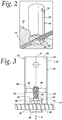
- a construction component or fixture 10 is shown as cast into a reinforced concrete structure 12 including a grid of rebar 14, with a portion of the concrete being removed to expose a forward half of the fixture 10 and portions of the rebar 14 and with the remainder of the fixture 10 and the rebar 14 within the concrete of the structure 12 being shown in phantom.
- the fixture 10 includes a socket 16 and a clamp 18 configured to sandwich a rebar 14 against the fixture 10 to position the socket 16 relative to the rebar 14 prior to casting the fixture 10 and the rebar 14 into the concrete structure 12.
- the socket 16 is configured to receive another construction component or fixture, such as, for example, a post (not shown) that can in turn support a mesh barrier or other containment structure for an edge protection system.
- a post not shown
- an array of the fixtures 10 can be connected to the rebar 14 to provide support for a series of posts in the concrete structure 12, such as a linear array of fixtures 10 to support a linear array of posts with a mesh barrier extending from post to post.
- the illustrated socket 16 is provided in the form of a cylindrical-shaped metal tube 20 centered on a longitudinal axis 21 and having a cylindrical interior surface 22 and a cylindrical exterior surface 24, with the interior surface 22 sized to receive the cylindrical exterior surface of a cylindrical post or the cylindrical outer surface of a plastic sleeve which in turn has a cylindrical interior surface to receive a cylindrical post.
- the clamp 18 includes a hook 26 shaped to engage around the rebar 14, with the hook 26 being mounted to the fixture 10 to translate along the axis 21 relative to the socket 16, as illustrated by arrows A in Figs. 3 and 4 .
- the fixture 10 includes a clamp mount bracket 28 fixed to the socket 16 by any suitable means, such as, for example, via welding or other suitable bonding to the interior surface 22 of the socket 16 as shown at 29 in Figs. 3 and 4 .
- the mount bracket 28 includes an opening 30 for receiving a shank or shaft 32 of the hook 26 to guide the hook 26 for translation along the axis 21.
- the shank 32 has external threads (shown diagrammatically at 34) that mate with internal threads (shown diagrammatically at 36) in the opening 30 so that relative rotation between the hook 26 and the socket 16 will cause the hook 26 to translate along the axis 21 relative to the socket 16.
- the hook 26 is a two piece fabrication, with a U-shaped, rebar receiving portion 40 having a threaded bolt 42 extending through an upper leg 43 of the portion 40 to define the threaded shank 32, and the U-shaped portion 40 and the bolt 42 being bonded by any suitable means, such as, for example, by welding or brazing.
- FIG. 5 illustrates an alternate embodiment of the hook 26 wherein the shank 32 is provided in the form of a threaded stud 44 extending upwardly from the U-shaped portion 40, with the threaded stud and the U-shaped portion either being machined from a single piece of material or joined together by any suitable means of bonding, such as, for example, via welding.
- the U-shaped portion 40 can be provided with a lower leg 46 having a slightly V-shaped configuration to somewhat conform to the rebar 14.
- the fixture 10 is installed onto a rebar 14 with the clamp 18 in an open condition spaced from the rebar 14, as shown in Fig.
- the socket 16 is rotated (as shown by arrow B) relative to the hook 26 and the rebar 14 to tighten the clamp 18 by translating the hook 26 along the axis 21 via the mating action of the threads 34,36 to create clamping forces against the rebar 14, as shown by arrows C in Fig. 4 .
- Figs. 6-33 show several alternate embodiments for the fixture 10, with like reference numbers indicating like components in the drawings.
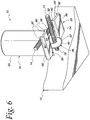
- Figs. 6-13 illustrate an embodiment according to the invention of the fixture 10 that differs in a number of ways from the embodiment shown in Figs. 1-5 .
- the fixture 10 of Figs. 6-13 includes a pair of catch plates 50 defining surfaces 52 and/or 54 extending from the socket 16 for engagement with the rebar 14.
- the catch plates 50 are provided in the form of a pair of feet 56 extending forward laterally from an end 58 of the socket 16 adjacent the hook 26, with each of the feet 56 having a pair of flanges 60 that serve to strengthen the feet 56.
- the hook 26 is formed from a single piece of material 57 having a generally circular cross section, with the single piece of material defining both the U-shaped portion 40 and the shank 32, with the U-shaped portion 40 being semicircular in shape for engagement with the rebar 14.
- the catch plates 50 are a unitary, single piece construction that includes the clamp mount bracket 28 and can be formed using any suitable method, such as via stamping, forging, or machining from a single piece of material. Rather than the opening 30 being threaded as in the embodiment of Figs. 1-5 , the opening 30 in the embodiment of Figs.
- the fixture 10 further includes a threaded nut 62 having internal threads 36 that mate with the external threads 34 of the shank 32.
- the clamp 18 is installed in the open condition and the nut 62 is rotated relative to the socket 16 and the hook 26 to translate the hook 26 to the closed condition in engagement with the rebar 14 via the action of the mating threads 34,36.
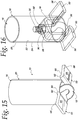
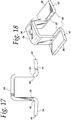
- Figs. 14-18 illustrate another embodiment of the fixture 10 that is very similar to the embodiment shown in Figs. 6-13 except that the feet 56 are provided with a single flange 60 rather than a pair of flanges 60.
- Figs. 19-21 illustrate another embodiment that differs from the embodiments of Figs. 6-18 in that the feet 56 have a primarily vertically extending cross section, rather than a primarily horizontally extending cross section as in the embodiments of Figs. 6-18 .
- Figs. 22-24 illustrate another embodiment of the fixture 10 that is very similar to the embodiments shown in Figs. 6-21 except that, in the embodiment of Figs. 22-24 , the catch plates 50 do not include feet 56 that extend in a laterally forward direction from the socket 16.
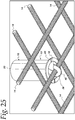
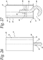
- Figs. 25-28 illustrate another alternate embodiment of the fixture 10 that differs from the embodiments of Figs. 6-24 in that the embodiment of Figs. 25-28 includes an annular flange 64 fixed to the end 58 of the socket 16 to define the surface 54 for engaging the rebar 14, rather than including the catch plates 50. Additionally, the mount bracket 28 is a separate component from the annular flange 64.
- Figs. 29-33 illustrate yet another embodiment of the fixture 10 that differs from the embodiment of Figs. 25-28 in that a pair of catch plates 68 are fixed to the sides of the socket 16 to extend in a laterally forward direction therefrom to define the surfaces 52,54, rather than having an annular flange 64 as in the embodiment of Figs. 25-28 .
- the catch plates 68 have a primarily vertical cross-section, but differ in that they provide a pair of curved surfaces 52,54 for engagement with the rebar 14 rather than flat surfaces 52.
- the fixture 10 can be attached directly to the rebar 14 and thereby benefit from the strength of the steel rebar in addition to the strength of the surrounding concrete in the concrete structure 12. Further, it should be appreciated that by minimizing the parts extending from the socket 16, the fixture 10 can be packaged with relative ease and with a significant density of the fixtures 10 in each packing container, thereby optimizing the transportation of the fixtures 10 before assembly into a concrete structure 12. It should be further appreciated that by providing the clamp 18 to directly attach the fixture 10 to the rebar 14, the fixture 10 doesn't require any additional tying of the fixture 10 to the rebar, thereby reducing labor costs and materials in comparison to conventional fixtures 10.
- the fixture 10 can be mounted to the rebar 14 to extend normal from the rebar 14 without any additional effort other than tightening of the clamp 26. It should also be appreciated that because the fixture 10 attaches directly to the rebar 14, the fixture 10 is self-regulating with respect to the concrete cover provided for the fixture 10 in the finished concrete structure 12, without requiring additional spacers as in conventional fixtures.
Landscapes
- Engineering & Computer Science (AREA)
- Architecture (AREA)
- Civil Engineering (AREA)
- Structural Engineering (AREA)
- Physics & Mathematics (AREA)
- Electromagnetism (AREA)
- Mechanical Engineering (AREA)
- Reinforcement Elements For Buildings (AREA)
- Joining Of Building Structures In Genera (AREA)
Claims (10)
- Halterung (10) zum Gießen in eine Betonstruktur (12) einschließlich Verstärkungsstangen (14), wobei die Halterung (10) Folgendes umfasst:eine Fassung (16) zur Aufnahme einer Baukomponente oder einer weiteren Halterung;eine Klemme (18), die so konfiguriert ist, dass sie eine Verstärkungsstange (14) in Sandwichform gegen die Halterung (10) umschließt, um die Fassung (16) in Bezug auf die Verstärkungsstange (14) vor dem Gießen der Halterung (10) und der Verstärkungsstange (14) in eine Betonstruktur (12) zu positionieren,dadurch gekennzeichnet, dass
die Klemme (18) Folgendes umfasst:einen Haken (26), der so geformt ist, dass er um eine Verstärkungsstange (14) greift;einen Gewindeschaft (32), der sich von dem Haken (26) aus erstreckt; undein Gewindeelement (36), das mit dem Gewindeschaft (32) ineinandergreift, um den Haken (26) in Bezug auf die restliche Halterung (10) zu übertragen;und eine Klemmenhalterung (28), die an der Fassung (16) befestigt ist, wobei die Klemmenhalterung (28) eine Öffnung (30) für die Aufnahme des Gewindeschafts (32) aufweist;wobei der Gewindeschaft (32) und der Haken (26) aus einem einzigen Materialstück (57) geformt sind. - Halterung (10) nach Anspruch 1, wobei die Fassung (16) eine zylindrische Innenfläche (22) und/oder eine zylindrische Außenfläche (24) aufweist.
- Halterung (10) nach einem der Ansprüche 1 oder 2, wobei die Fassung (16) in Form einer zylindrisch geformten Metallröhre (20) vorliegt.
- Halterung (10) nach Anspruch 1, wobei das Gewindeelement (36) in Form der Öffnung (30) als eine Gewindeöffnung (30) vorliegt, die so konfiguriert ist, dass sie über ein Gewinde mit dem Gewindeschaft (32) ineinandergreift.
- Halterung (10) nach Anspruch 1, wobei der Schaft (32) verschiebbar in der Öffnung (30) der Klemmenhalterung (28) aufgenommen ist und die Halterung (10) ferner ein Gewindeglied (62) aufweist, das das Gewindeelement (36) bildet, welches über ein Gewinde mit dem Gewindeschaft (32) ineinandergreift und gegen die Klemmenhalterung (28) anstößt.
- Halterung (10) nach einem der vorstehenden Ansprüche, die ferner mindestens eine Fläche (52, 54) aufweist, die sich von der Fassung (16) aus zwecks Eingreifen mit einer Verstärkungsstange (14) erstreckt.
- Halterung (10) nach Anspruch 6, die ferner mindestens ein Fangblech (50) umfasst, das die mindestens eine Fläche (52, 54) bildet, wobei das mindestens eine Fangblech (50) an einem Ende (58) der Fassung (16) angrenzend an die Klemme (18) befestigt ist.
- Halterung (10) nach Anspruch 7, wobei das Fangblech (50) ein Paar Füße (56) umfasst, die sich von der Fassung (16) aus auf gegenüberliegenden Seiten der Klemme (18) erstrecken.
- Halterung (10) nach Anspruch 8, wobei mindestens einer des Paars Füße (56) einen Versteifungsteil (60) aufweist, der sich entlang des mindestens einen des Paars Füße (56) erstreckt.
- Halterung (10) nach einem der Ansprüche 7, 8 oder 9, wobei das Fangblech (50) und die Klemmenhalterung (28) aus einem einzigen Materialstück (57) geformt sind.
Applications Claiming Priority (1)
| Application Number | Priority Date | Filing Date | Title |
|---|---|---|---|
| US201261648001P | 2012-05-16 | 2012-05-16 |
Publications (3)
| Publication Number | Publication Date |
|---|---|
| EP2664732A2 EP2664732A2 (de) | 2013-11-20 |
| EP2664732A3 EP2664732A3 (de) | 2014-11-05 |
| EP2664732B1 true EP2664732B1 (de) | 2017-04-19 |
Family
ID=48430499
Family Applications (1)
| Application Number | Title | Priority Date | Filing Date |
|---|---|---|---|
| EP13167509.2A Active EP2664732B1 (de) | 2012-05-16 | 2013-05-13 | Buchse für die Befestigung zur erneuten Stangenbildung und Guss in eine Betonstruktur |
Country Status (1)
| Country | Link |
|---|---|
| EP (1) | EP2664732B1 (de) |
Families Citing this family (2)
| Publication number | Priority date | Publication date | Assignee | Title |
|---|---|---|---|---|
| FR3085981B1 (fr) * | 2018-09-17 | 2021-10-22 | Somain Securite | Dispositif de fixation d'un poteau sur un grillage |
| CN114633063B (zh) * | 2022-03-30 | 2023-06-13 | 阿博机器人(昆山)有限公司 | Lp墙体构件焊接台模 |
Citations (4)
| Publication number | Priority date | Publication date | Assignee | Title |
|---|---|---|---|---|
| BE712169A (de) * | 1968-03-14 | 1968-09-16 | ||
| FR2574697A2 (fr) * | 1983-03-31 | 1986-06-20 | Laroche Francis | Dispositif d'ancrage |
| WO1996021065A1 (en) * | 1995-01-06 | 1996-07-11 | The Burke Group | Concrete structure having load transferring insert and method for making same |
| JP2007009411A (ja) * | 2005-06-02 | 2007-01-18 | Toshihisa Ebara | アンカーボルトの位置保持用金具及び位置固定構造,それを利用した鉄骨柱の建て方方法 |
Family Cites Families (2)
| Publication number | Priority date | Publication date | Assignee | Title |
|---|---|---|---|---|
| DD27694A (de) * | ||||
| FR2543481B1 (fr) * | 1983-03-31 | 1986-03-14 | Francis Laroche | Dispositif d'ancrage dans le beton |
-
2013
- 2013-05-13 EP EP13167509.2A patent/EP2664732B1/de active Active
Patent Citations (4)
| Publication number | Priority date | Publication date | Assignee | Title |
|---|---|---|---|---|
| BE712169A (de) * | 1968-03-14 | 1968-09-16 | ||
| FR2574697A2 (fr) * | 1983-03-31 | 1986-06-20 | Laroche Francis | Dispositif d'ancrage |
| WO1996021065A1 (en) * | 1995-01-06 | 1996-07-11 | The Burke Group | Concrete structure having load transferring insert and method for making same |
| JP2007009411A (ja) * | 2005-06-02 | 2007-01-18 | Toshihisa Ebara | アンカーボルトの位置保持用金具及び位置固定構造,それを利用した鉄骨柱の建て方方法 |
Also Published As
| Publication number | Publication date |
|---|---|
| EP2664732A3 (de) | 2014-11-05 |
| EP2664732A2 (de) | 2013-11-20 |
Similar Documents
| Publication | Publication Date | Title |
|---|---|---|
| AU2013201397B2 (en) | Wooden member assembly | |
| EP2966236A1 (de) | Verbindungsvorrichtung für Stahlbeton-Fertigtsäulen mit trockener Fuge | |
| US9840838B2 (en) | Anchor rail | |
| KR101627834B1 (ko) | 띠철근 고정구, 원터치 체결 띠철근 및 띠철근 고정구에 의해 띠철근이 결합된 철근콘크리트 부재 | |
| RU2705530C1 (ru) | Соединительное тело, кольцевой сегмент башни ветроэнергетической установки и способ соединения двух кольцевых сегментов башни ветроэнергетической установки | |
| KR20130091938A (ko) | 단부 정착된 강재와 와이어로프를 이용한 기둥 내력보강방법 | |
| KR101602595B1 (ko) | 산업용 기계를 위한 기초 앵커 | |
| KR20230168990A (ko) | 철근 배치구조 조정이 가능한 철근 일체화 스마트 정착장치를 이용한 무용접 철근 정착방법 | |
| EP2664732A2 (de) | Buchse für die Befestigung zur erneuten Stangenbildung und Guss in eine Betonstruktur | |
| US20100170166A1 (en) | Spot footing | |
| KR102076367B1 (ko) | 철근 커플러 | |
| CN210949688U (zh) | 一种钢丝绳张紧支架装置 | |
| JP4081602B2 (ja) | 鋼コンクリート合成構造と鉄筋コンクリート構造の接合部構造 | |
| JPH09100822A (ja) | ベースプレートとアンカーボルトの固定法及びそのベースプレート、アンカーボルトとナット | |
| KR101583338B1 (ko) | 프리캐스트 src기둥과 프리캐스트 src보의 셀프포지셔닝 연결구조 | |
| EP2696011A2 (de) | Erdbebensichere Verbindungsvorrichtung zur Verbindung von Strukturelementen | |
| EP2395252A1 (de) | Verbindungsanordnung und Verfahren zur Befestigung einer Schraube | |
| CN109736486A (zh) | 一种预制外墙的挂装点安全构造及其制作方法 | |
| KR20070072332A (ko) | 강관의 두부 보강장치 | |
| CN210195260U (zh) | 一种螺纹拼装式对拉螺栓 | |
| KR20110007309U (ko) | 기둥거푸집용 지지바 고정구 | |
| KR200426656Y1 (ko) | 강관의 두부 보강장치 | |
| KR102654544B1 (ko) | 관형지지물 및 이의 연결방법 | |
| JP2017101414A (ja) | テンションロッドの取り付け構造 | |
| DE202014105061U1 (de) | Transportanker zur Sicherung von Betonfertigteilen |
Legal Events
| Date | Code | Title | Description |
|---|---|---|---|
| PUAI | Public reference made under article 153(3) epc to a published international application that has entered the european phase |
Free format text: ORIGINAL CODE: 0009012 |
|
| 17P | Request for examination filed |
Effective date: 20130513 |
|
| AK | Designated contracting states |
Kind code of ref document: A2 Designated state(s): AL AT BE BG CH CY CZ DE DK EE ES FI FR GB GR HR HU IE IS IT LI LT LU LV MC MK MT NL NO PL PT RO RS SE SI SK SM TR |
|
| AX | Request for extension of the european patent |
Extension state: BA ME |
|
| PUAL | Search report despatched |
Free format text: ORIGINAL CODE: 0009013 |
|
| AK | Designated contracting states |
Kind code of ref document: A3 Designated state(s): AL AT BE BG CH CY CZ DE DK EE ES FI FR GB GR HR HU IE IS IT LI LT LU LV MC MK MT NL NO PL PT RO RS SE SI SK SM TR |
|
| AX | Request for extension of the european patent |
Extension state: BA ME |
|
| RIC1 | Information provided on ipc code assigned before grant |
Ipc: E04B 1/41 20060101ALN20140926BHEP Ipc: E04F 11/18 20060101ALI20140926BHEP Ipc: E04G 21/18 20060101AFI20140926BHEP |
|
| 17Q | First examination report despatched |
Effective date: 20141111 |
|
| RAP1 | Party data changed (applicant data changed or rights of an application transferred) |
Owner name: HONEYWELL INTERNATIONAL INC. |
|
| GRAP | Despatch of communication of intention to grant a patent |
Free format text: ORIGINAL CODE: EPIDOSNIGR1 |
|
| INTG | Intention to grant announced |
Effective date: 20161125 |
|
| RIC1 | Information provided on ipc code assigned before grant |
Ipc: E04G 21/18 20060101AFI20161115BHEP Ipc: E04F 11/18 20060101ALI20161115BHEP Ipc: E04B 1/41 20060101ALN20161115BHEP |
|
| GRAS | Grant fee paid |
Free format text: ORIGINAL CODE: EPIDOSNIGR3 |
|
| GRAA | (expected) grant |
Free format text: ORIGINAL CODE: 0009210 |
|
| AK | Designated contracting states |
Kind code of ref document: B1 Designated state(s): AL AT BE BG CH CY CZ DE DK EE ES FI FR GB GR HR HU IE IS IT LI LT LU LV MC MK MT NL NO PL PT RO RS SE SI SK SM TR |
|
| REG | Reference to a national code |
Ref country code: GB Ref legal event code: FG4D |
|
| REG | Reference to a national code |
Ref country code: CH Ref legal event code: EP |
|
| REG | Reference to a national code |
Ref country code: AT Ref legal event code: REF Ref document number: 886123 Country of ref document: AT Kind code of ref document: T Effective date: 20170515 |
|
| REG | Reference to a national code |
Ref country code: IE Ref legal event code: FG4D |
|
| REG | Reference to a national code |
Ref country code: FR Ref legal event code: PLFP Year of fee payment: 5 |
|
| REG | Reference to a national code |
Ref country code: DE Ref legal event code: R096 Ref document number: 602013019931 Country of ref document: DE |
|
| REG | Reference to a national code |
Ref country code: NL Ref legal event code: MP Effective date: 20170419 |
|
| REG | Reference to a national code |
Ref country code: LT Ref legal event code: MG4D |
|
| REG | Reference to a national code |
Ref country code: AT Ref legal event code: MK05 Ref document number: 886123 Country of ref document: AT Kind code of ref document: T Effective date: 20170419 |
|
| PG25 | Lapsed in a contracting state [announced via postgrant information from national office to epo] |
Ref country code: NL Free format text: LAPSE BECAUSE OF FAILURE TO SUBMIT A TRANSLATION OF THE DESCRIPTION OR TO PAY THE FEE WITHIN THE PRESCRIBED TIME-LIMIT Effective date: 20170419 |
|
| PG25 | Lapsed in a contracting state [announced via postgrant information from national office to epo] |
Ref country code: LT Free format text: LAPSE BECAUSE OF FAILURE TO SUBMIT A TRANSLATION OF THE DESCRIPTION OR TO PAY THE FEE WITHIN THE PRESCRIBED TIME-LIMIT Effective date: 20170419 Ref country code: GR Free format text: LAPSE BECAUSE OF FAILURE TO SUBMIT A TRANSLATION OF THE DESCRIPTION OR TO PAY THE FEE WITHIN THE PRESCRIBED TIME-LIMIT Effective date: 20170720 Ref country code: ES Free format text: LAPSE BECAUSE OF FAILURE TO SUBMIT A TRANSLATION OF THE DESCRIPTION OR TO PAY THE FEE WITHIN THE PRESCRIBED TIME-LIMIT Effective date: 20170419 Ref country code: AT Free format text: LAPSE BECAUSE OF FAILURE TO SUBMIT A TRANSLATION OF THE DESCRIPTION OR TO PAY THE FEE WITHIN THE PRESCRIBED TIME-LIMIT Effective date: 20170419 Ref country code: FI Free format text: LAPSE BECAUSE OF FAILURE TO SUBMIT A TRANSLATION OF THE DESCRIPTION OR TO PAY THE FEE WITHIN THE PRESCRIBED TIME-LIMIT Effective date: 20170419 Ref country code: HR Free format text: LAPSE BECAUSE OF FAILURE TO SUBMIT A TRANSLATION OF THE DESCRIPTION OR TO PAY THE FEE WITHIN THE PRESCRIBED TIME-LIMIT Effective date: 20170419 Ref country code: NO Free format text: LAPSE BECAUSE OF FAILURE TO SUBMIT A TRANSLATION OF THE DESCRIPTION OR TO PAY THE FEE WITHIN THE PRESCRIBED TIME-LIMIT Effective date: 20170719 |
|
| PG25 | Lapsed in a contracting state [announced via postgrant information from national office to epo] |
Ref country code: RS Free format text: LAPSE BECAUSE OF FAILURE TO SUBMIT A TRANSLATION OF THE DESCRIPTION OR TO PAY THE FEE WITHIN THE PRESCRIBED TIME-LIMIT Effective date: 20170419 Ref country code: SE Free format text: LAPSE BECAUSE OF FAILURE TO SUBMIT A TRANSLATION OF THE DESCRIPTION OR TO PAY THE FEE WITHIN THE PRESCRIBED TIME-LIMIT Effective date: 20170419 Ref country code: PL Free format text: LAPSE BECAUSE OF FAILURE TO SUBMIT A TRANSLATION OF THE DESCRIPTION OR TO PAY THE FEE WITHIN THE PRESCRIBED TIME-LIMIT Effective date: 20170419 Ref country code: BG Free format text: LAPSE BECAUSE OF FAILURE TO SUBMIT A TRANSLATION OF THE DESCRIPTION OR TO PAY THE FEE WITHIN THE PRESCRIBED TIME-LIMIT Effective date: 20170719 Ref country code: LV Free format text: LAPSE BECAUSE OF FAILURE TO SUBMIT A TRANSLATION OF THE DESCRIPTION OR TO PAY THE FEE WITHIN THE PRESCRIBED TIME-LIMIT Effective date: 20170419 Ref country code: IS Free format text: LAPSE BECAUSE OF FAILURE TO SUBMIT A TRANSLATION OF THE DESCRIPTION OR TO PAY THE FEE WITHIN THE PRESCRIBED TIME-LIMIT Effective date: 20170819 |
|
| REG | Reference to a national code |
Ref country code: CH Ref legal event code: PL |
|
| REG | Reference to a national code |
Ref country code: DE Ref legal event code: R097 Ref document number: 602013019931 Country of ref document: DE |
|
| PG25 | Lapsed in a contracting state [announced via postgrant information from national office to epo] |
Ref country code: MC Free format text: LAPSE BECAUSE OF FAILURE TO SUBMIT A TRANSLATION OF THE DESCRIPTION OR TO PAY THE FEE WITHIN THE PRESCRIBED TIME-LIMIT Effective date: 20170419 Ref country code: DK Free format text: LAPSE BECAUSE OF FAILURE TO SUBMIT A TRANSLATION OF THE DESCRIPTION OR TO PAY THE FEE WITHIN THE PRESCRIBED TIME-LIMIT Effective date: 20170419 Ref country code: CZ Free format text: LAPSE BECAUSE OF FAILURE TO SUBMIT A TRANSLATION OF THE DESCRIPTION OR TO PAY THE FEE WITHIN THE PRESCRIBED TIME-LIMIT Effective date: 20170419 Ref country code: EE Free format text: LAPSE BECAUSE OF FAILURE TO SUBMIT A TRANSLATION OF THE DESCRIPTION OR TO PAY THE FEE WITHIN THE PRESCRIBED TIME-LIMIT Effective date: 20170419 Ref country code: SK Free format text: LAPSE BECAUSE OF FAILURE TO SUBMIT A TRANSLATION OF THE DESCRIPTION OR TO PAY THE FEE WITHIN THE PRESCRIBED TIME-LIMIT Effective date: 20170419 Ref country code: RO Free format text: LAPSE BECAUSE OF FAILURE TO SUBMIT A TRANSLATION OF THE DESCRIPTION OR TO PAY THE FEE WITHIN THE PRESCRIBED TIME-LIMIT Effective date: 20170419 |
|
| REG | Reference to a national code |
Ref country code: IE Ref legal event code: MM4A |
|
| PLBE | No opposition filed within time limit |
Free format text: ORIGINAL CODE: 0009261 |
|
| STAA | Information on the status of an ep patent application or granted ep patent |
Free format text: STATUS: NO OPPOSITION FILED WITHIN TIME LIMIT |
|
| PG25 | Lapsed in a contracting state [announced via postgrant information from national office to epo] |
Ref country code: IT Free format text: LAPSE BECAUSE OF FAILURE TO SUBMIT A TRANSLATION OF THE DESCRIPTION OR TO PAY THE FEE WITHIN THE PRESCRIBED TIME-LIMIT Effective date: 20170419 Ref country code: SM Free format text: LAPSE BECAUSE OF FAILURE TO SUBMIT A TRANSLATION OF THE DESCRIPTION OR TO PAY THE FEE WITHIN THE PRESCRIBED TIME-LIMIT Effective date: 20170419 Ref country code: LI Free format text: LAPSE BECAUSE OF NON-PAYMENT OF DUE FEES Effective date: 20170531 Ref country code: CH Free format text: LAPSE BECAUSE OF NON-PAYMENT OF DUE FEES Effective date: 20170531 |
|
| 26N | No opposition filed |
Effective date: 20180122 |
|
| PG25 | Lapsed in a contracting state [announced via postgrant information from national office to epo] |
Ref country code: LU Free format text: LAPSE BECAUSE OF NON-PAYMENT OF DUE FEES Effective date: 20170513 |
|
| REG | Reference to a national code |
Ref country code: BE Ref legal event code: MM Effective date: 20170531 |
|
| PG25 | Lapsed in a contracting state [announced via postgrant information from national office to epo] |
Ref country code: IE Free format text: LAPSE BECAUSE OF NON-PAYMENT OF DUE FEES Effective date: 20170513 |
|
| REG | Reference to a national code |
Ref country code: FR Ref legal event code: PLFP Year of fee payment: 6 |
|
| PG25 | Lapsed in a contracting state [announced via postgrant information from national office to epo] |
Ref country code: SI Free format text: LAPSE BECAUSE OF FAILURE TO SUBMIT A TRANSLATION OF THE DESCRIPTION OR TO PAY THE FEE WITHIN THE PRESCRIBED TIME-LIMIT Effective date: 20170419 |
|
| PG25 | Lapsed in a contracting state [announced via postgrant information from national office to epo] |
Ref country code: BE Free format text: LAPSE BECAUSE OF NON-PAYMENT OF DUE FEES Effective date: 20170531 |
|
| PG25 | Lapsed in a contracting state [announced via postgrant information from national office to epo] |
Ref country code: MT Free format text: LAPSE BECAUSE OF NON-PAYMENT OF DUE FEES Effective date: 20170513 |
|
| PG25 | Lapsed in a contracting state [announced via postgrant information from national office to epo] |
Ref country code: HU Free format text: LAPSE BECAUSE OF FAILURE TO SUBMIT A TRANSLATION OF THE DESCRIPTION OR TO PAY THE FEE WITHIN THE PRESCRIBED TIME-LIMIT; INVALID AB INITIO Effective date: 20130513 |
|
| PG25 | Lapsed in a contracting state [announced via postgrant information from national office to epo] |
Ref country code: CY Free format text: LAPSE BECAUSE OF NON-PAYMENT OF DUE FEES Effective date: 20170419 |
|
| PG25 | Lapsed in a contracting state [announced via postgrant information from national office to epo] |
Ref country code: MK Free format text: LAPSE BECAUSE OF FAILURE TO SUBMIT A TRANSLATION OF THE DESCRIPTION OR TO PAY THE FEE WITHIN THE PRESCRIBED TIME-LIMIT Effective date: 20170419 |
|
| PG25 | Lapsed in a contracting state [announced via postgrant information from national office to epo] |
Ref country code: TR Free format text: LAPSE BECAUSE OF FAILURE TO SUBMIT A TRANSLATION OF THE DESCRIPTION OR TO PAY THE FEE WITHIN THE PRESCRIBED TIME-LIMIT Effective date: 20170419 |
|
| PG25 | Lapsed in a contracting state [announced via postgrant information from national office to epo] |
Ref country code: PT Free format text: LAPSE BECAUSE OF FAILURE TO SUBMIT A TRANSLATION OF THE DESCRIPTION OR TO PAY THE FEE WITHIN THE PRESCRIBED TIME-LIMIT Effective date: 20170419 |
|
| PG25 | Lapsed in a contracting state [announced via postgrant information from national office to epo] |
Ref country code: AL Free format text: LAPSE BECAUSE OF FAILURE TO SUBMIT A TRANSLATION OF THE DESCRIPTION OR TO PAY THE FEE WITHIN THE PRESCRIBED TIME-LIMIT Effective date: 20170419 |
|
| REG | Reference to a national code |
Ref country code: DE Ref legal event code: R081 Ref document number: 602013019931 Country of ref document: DE Owner name: HONEYWELL SAFETY PRODUCTS USA, INC., WILMINGTO, US Free format text: FORMER OWNER: HONEYWELL INTERNATIONAL INC., MORRIS PLAINS, N.J., US |
|
| REG | Reference to a national code |
Ref country code: GB Ref legal event code: 732E Free format text: REGISTERED BETWEEN 20250515 AND 20250521 |
|
| PGFP | Annual fee paid to national office [announced via postgrant information from national office to epo] |
Ref country code: DE Payment date: 20250528 Year of fee payment: 13 |
|
| PGFP | Annual fee paid to national office [announced via postgrant information from national office to epo] |
Ref country code: GB Payment date: 20250520 Year of fee payment: 13 |
|
| PGFP | Annual fee paid to national office [announced via postgrant information from national office to epo] |
Ref country code: FR Payment date: 20250526 Year of fee payment: 13 |