EP2664736A2 - Activation d'ensemble de moteur de verrou électronique - Google Patents
Activation d'ensemble de moteur de verrou électronique Download PDFInfo
- Publication number
- EP2664736A2 EP2664736A2 EP20130167072 EP13167072A EP2664736A2 EP 2664736 A2 EP2664736 A2 EP 2664736A2 EP 20130167072 EP20130167072 EP 20130167072 EP 13167072 A EP13167072 A EP 13167072A EP 2664736 A2 EP2664736 A2 EP 2664736A2
- Authority
- EP
- European Patent Office
- Prior art keywords
- positioning
- actuating motor
- motor set
- clutch member
- tooth
- Prior art date
- Legal status (The legal status is an assumption and is not a legal conclusion. Google has not performed a legal analysis and makes no representation as to the accuracy of the status listed.)
- Granted
Links
Images






Classifications
-
- E—FIXED CONSTRUCTIONS
- E05—LOCKS; KEYS; WINDOW OR DOOR FITTINGS; SAFES
- E05B—LOCKS; ACCESSORIES THEREFOR; HANDCUFFS
- E05B47/00—Operating or controlling locks or other fastening devices by electric or magnetic means
- E05B47/0001—Operating or controlling locks or other fastening devices by electric or magnetic means with electric actuators; Constructional features thereof
- E05B47/0012—Operating or controlling locks or other fastening devices by electric or magnetic means with electric actuators; Constructional features thereof with rotary electromotors
-
- E—FIXED CONSTRUCTIONS
- E05—LOCKS; KEYS; WINDOW OR DOOR FITTINGS; SAFES
- E05B—LOCKS; ACCESSORIES THEREFOR; HANDCUFFS
- E05B47/00—Operating or controlling locks or other fastening devices by electric or magnetic means
- E05B47/06—Controlling mechanically-operated bolts by electro-magnetically-operated detents
- E05B47/0611—Cylinder locks with electromagnetic control
- E05B47/0615—Cylinder locks with electromagnetic control operated by handles, e.g. by knobs
-
- E—FIXED CONSTRUCTIONS
- E05—LOCKS; KEYS; WINDOW OR DOOR FITTINGS; SAFES
- E05B—LOCKS; ACCESSORIES THEREFOR; HANDCUFFS
- E05B47/00—Operating or controlling locks or other fastening devices by electric or magnetic means
- E05B47/06—Controlling mechanically-operated bolts by electro-magnetically-operated detents
- E05B47/0611—Cylinder locks with electromagnetic control
- E05B47/0638—Cylinder locks with electromagnetic control by disconnecting the rotor
- E05B47/0642—Cylinder locks with electromagnetic control by disconnecting the rotor axially, i.e. with an axially disengaging coupling element
-
- E—FIXED CONSTRUCTIONS
- E05—LOCKS; KEYS; WINDOW OR DOOR FITTINGS; SAFES
- E05B—LOCKS; ACCESSORIES THEREFOR; HANDCUFFS
- E05B15/00—Other details of locks; Parts for engagement by bolts of fastening devices
- E05B15/04—Spring arrangements in locks
- E05B2015/0403—Wound springs
- E05B2015/0424—Wound springs of conical shape
-
- E—FIXED CONSTRUCTIONS
- E05—LOCKS; KEYS; WINDOW OR DOOR FITTINGS; SAFES
- E05B—LOCKS; ACCESSORIES THEREFOR; HANDCUFFS
- E05B47/00—Operating or controlling locks or other fastening devices by electric or magnetic means
- E05B47/0001—Operating or controlling locks or other fastening devices by electric or magnetic means with electric actuators; Constructional features thereof
- E05B2047/0014—Constructional features of actuators or power transmissions therefor
- E05B2047/0018—Details of actuator transmissions
- E05B2047/0023—Nuts or nut-like elements moving along a driven threaded axle
-
- E—FIXED CONSTRUCTIONS
- E05—LOCKS; KEYS; WINDOW OR DOOR FITTINGS; SAFES
- E05B—LOCKS; ACCESSORIES THEREFOR; HANDCUFFS
- E05B47/00—Operating or controlling locks or other fastening devices by electric or magnetic means
- E05B47/0001—Operating or controlling locks or other fastening devices by electric or magnetic means with electric actuators; Constructional features thereof
- E05B2047/0014—Constructional features of actuators or power transmissions therefor
- E05B2047/0018—Details of actuator transmissions
- E05B2047/0026—Clutches, couplings or braking arrangements
- E05B2047/0031—Clutches, couplings or braking arrangements of the elastic type
-
- Y—GENERAL TAGGING OF NEW TECHNOLOGICAL DEVELOPMENTS; GENERAL TAGGING OF CROSS-SECTIONAL TECHNOLOGIES SPANNING OVER SEVERAL SECTIONS OF THE IPC; TECHNICAL SUBJECTS COVERED BY FORMER USPC CROSS-REFERENCE ART COLLECTIONS [XRACs] AND DIGESTS
- Y10—TECHNICAL SUBJECTS COVERED BY FORMER USPC
- Y10T—TECHNICAL SUBJECTS COVERED BY FORMER US CLASSIFICATION
- Y10T70/00—Locks
- Y10T70/70—Operating mechanism
- Y10T70/7051—Using a powered device [e.g., motor]
- Y10T70/7062—Electrical type [e.g., solenoid]
- Y10T70/7102—And details of blocking system [e.g., linkage, latch, pawl, spring]
Definitions
- the present invention relates to an actuating motor set, and especially to an actuating motor set installed in an electronic lock.
- a conventional mechanical lock is configured with a lock core and lock bolt, so each lock can only be opened with a dedicated key.
- this kind of locks can be unlocked with special mechanical tools easily.
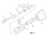
- FIG. 1 shows the structure of a conventional electronic lock to include a lock core 20 connected with a clutch 30; a cam 40; an actuating motor set 50 and a turning core 60.
- the components listed above are installed in a casing 70, and then the casing is connected to the turning knob 80 with an end of the turning core 60.
- the key 10 can go through the key groove and push against the front clutch member 31 backwards.
- the chip on the key 10 can send a pass code/data stored within to the electronic lock control system for identification through electronic contact sensing.
- the purpose of the actuating motor set is to prepare the lock for its pre-unlocking state. If the actuating motor is malfunctioned, the electronic lock cannot be unlocked even if the key matches with the lock itself mechanically and electronically. Therefore, the actuating motor set 50 plays a considerably important role in the electronic actuating mechanism of the electronic locks. In other words, the actuating method and the malfunction rate of the actuating motor set 50 can deeply affect the usage life and the effect of electronic locks.
- the conventional actuating motor set does not include a position limiting mechanism to limit the components connected, therefore, when the components moves forward or backward with the drive of the motor, they usually overshoot and end up pushing other components.
- the primary purpose of the present invention is to provide an actuating motor set with a simplified position limiting driving component.
- the actuating motor of the present invention can drive components more precisely, prevent overshoot, prolong the usage life of the motor, lower the malfunction rate of the electronic lock, simplify the manufacturing process and also decrease the production costs.
- the actuating motor set of electronic lock of the present invention includes the following components: a mounting base including a chamber; a motor connected to the mounting base and having a rotating shaft; a transmission set including a worm gear.
- the worm gear is connected to the rotating shaft, and a tooth distributed not all the way to two opposite ends of the worm gear. The two ends respectively defining a pushing end and a restoring end; and a spring including an engagement part and an abutment part.
- the engagement part is engaged with the tooth, and a remaining part of the spring defines the abutment part.
- An inner diameter of the abutment part is larger than an outer diameter of the tooth.
- the abutment part further abuts against a rear clutch member, where the rear clutch member has a sliding groove for connecting within the chamber.
- the chamber includes a corresponding rib, so the rear clutch member can slide within the chamber.
- the engagement part is an open spiral structure, and is engaged to the worm gear by setting the inner diameter of the spiral structure of the engagement part to be smaller than the outer diameter of the tooth.
- the engagement part is bent toward the worm gear to form a horizontal hook to be engaged with the tooth, where the position of the engagement is also smaller than the outer diameter of the tooth.
- the worm gear rotates together with the actuating motor, and the engagement part of the spring engaging with the tooth is pushed toward the rear clutch member during the rotation, so the rear clutch member which is abutted against by the spring is pushed outward gradually.
- the engagement part of the spring is pushed to the pushing end, the spring is not pushed further forward since there is no tooth at the pushing end to push the spring.
- the spring is then hold at certain position by the rotating tooth when it falls back, thereby limiting the position of the spring at the pushing end and preventing overshoot situation.
- the engagement part of the spring is pulled toward the motor side by the engaged tooth.
- the present invention can achieve the goal of providing driving force and position limiting with simplest components, thereby preventing the overshoot situation by the driving of the motor.
- the spring is moved back and forth on the axial direction of the worm gear, additional rooms for installing other components are not required, and the size of the product can be reduced.
- the manufacturing process can be simplified and the production cost can also be lowered, thereby enhancing the competitiveness of the product.
- the rear clutch member includes: a base, two positioning sliders and a second extending tube.
- the base includes two through holes and two restricting portion, wherein a buffer space is formed between two restricting portion.
- a resilient member is connected between the two positioning sliders.
- the two positioning sliders, each formed with a positioning portion on the outer periphery thereof, are fitted in the buffer space such that the two positioning slider can slide toward or away from each other via the resilience of the resilient member in the buffer space.
- the second extending tube abuts against the abutment part, where a clutch block is connected to the other end of the second extending tube opposite from the abutment part.
- the clutch block includes at least one latching protrusion which abuts the second extending tube at the abutment part, and protrudes from the respective through hole.
- the cam includes two positioning groove for coupling with the positioning portion of the positioning slider, and includes at least one latching groove for latching with the at least one latching protrusion.
- the two positioning sliders of the rear clutch member are pushed away from each other by the resilience of the resilient member in such way that each of positioning slider is abutted and coupled to the positioning groove.
- the resilience of the resilient member serves as the buffer for such movement and then further disengages the coupling between the two positioning sliders and the positioning groove.
- the rotation of the base does not rotate the cam.
- the motor is activated and the abutment part of the spring is moved, the second extending tube is also abutted to move toward the base. Meanwhile, the latching protrusion connected to the second extending tube then protrudes outward from the through hole on the base to further latch with the latching groove of the cam. Under this state, the lock can be opened via the rotation of the cam by the rotation of the base.
- Fig. 1 is a exploded view showing a conventional electronic lock
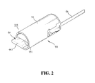
- Fig. 2 is a schematic view showing the first embodiment of an actuating motor set of the present invention for an electronic lock
- Fig. 3 is a perspective exploded view showing the first embodiment of the actuating motor set of the present invention
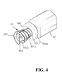
- Fig. 4 is a partial assembly view showing the first embodiment of the actuating motor set of the present invention.
- Fig. 5 is a side section view showing the first embodiment of the actuating motor set of the present invention.
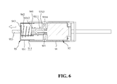
- Fig. 6 is a schematic view showing the actuation of the first embodiment of the actuating motor set of the present invention.
- Fig. 7 is an exploded view showing the second embodiment of the actuating motor set of the present invention.
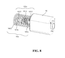
- Fig. 8 is a partial assembly view showing the second embodiment of the actuating motor set of the present invention.
- Fig. 9 is a partial side view showing the second embodiment of the actuating motor set of the present invention.
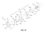
- Fig. 10 is an exploded view showing the rear clutch member according to the third embodiment of the present invention.
- Fig. 11 is an assembly view showing the rear clutch member according to the third embodiment of the present invention.
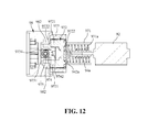
- Fig. 12 is a side view showing the rear clutch member according to the third embodiment of the present invention.
- Fig. 13 is a schematic view showing the actuation of the rear clutch member according to the third embodiment of the present invention.
- Fig. 2 is schematic view showing the appearance of the first embodiment of the actuating motor set of the present invention
- Fig. 3 is a perspective exploded view
- Fig. 4 is an assembly view showing the first embodiment of the actuating motor set the present invention.
- the actuating motor set 90 of an electronic lock includes a spring 94 which is abutted against a rear clutch member 95.
- the rear clutch member 95 is installed in the mounting base 91 and is slidable within a chamber 911 of the mounting base 91.
- the transmission set 93 pushes the spring 94
- the rear clutch member 95 also slides outward from the chamber 911 and connects with the front clutch member 31 (as shown in Fig. 1 ), thereby unlocking the electronic lock.
- the actuating motor set 90 of the first embodiment of the actuating motor set of the present invention includes the following components: a mounting base 91, a motor 92, a transmission set 93 and a spring 94.
- the configuration of the mounting base 91 is not limited by the present invention specifically; it can be an integrally formed body as the present embodiment, an assembly of an upper and lower piece or can be in any other forms.
- the mounting base 91 is formed with a chamber 911, where the motor 92, transmission set 93 and spring 94 are installed, and the first extending tube 951 of the rear clutch member slides within.
- the shape of the first extending tube 951 should correspond to the shape of the chamber 911, so the first extending tube 951 can slide within the chamber 911.
- a sliding groove 952 can be formed on the outer peripheral of the first extending tube 951, and a corresponding rib 912 can be formed in the chamber 911.
- the sliding mechanism of the rear clutch member 95 and the chamber 911 is not limited to this embodiment, for example, the location of the rib and the sliding groove can be altered, or one can utilize rear clutch member 95 and chamber 911 with non-circular shape to limit the direction of sliding.
- the first extending tube 951 also has an engaging piece 953.
- the shape of the engaging piece 953 is also not specifically limited and can be adjusted according to the need of front clutch member or the shape of other corresponding components.
- the motor 92 is axially connected to a transmission set 93.
- the transmission set 93 includes a worm gear 931, which is axially connected to the rotating shaft 921.
- the worm gear 931 can be disposed on the rotating shaft 921 directly, or can also be connected in the configuration of the current embodiment.
- a connecting groove 9315 is formed first on the worm gear 921, and the rotating shaft 921 is axially connected to a connecting member 932, which is disposed in the connecting groove 9315.
- the worm gear 931 is connected to the rotating shaft 921 coaxially or eccentrically.
- a bearing (not visible) is further installed on the rotating shaft 921 between the connecting member 932 and the motor 92.
- the spring 94 When the spring 94 abuts and pushes the rear clutch member 95, it generates a pushing force in the opposite direction against the worm gear 931.
- the bearing serves as a cushion to reduce the pushing force, thereby reducing the rotation resistance generated in the worm gear 931 and prolonging the usage life of the transmission set 93.
- a tooth 9311 is formed on the worm gear 931, but the tooth does not extend to the pushing end 9312 and the restoring end 9313.
- the restoring end 9313 can further connects to a base 9314, which is used to abut against the pushing force of spring 94 when the spring 94 restores to its initial position.
- the spring 94 includes an engagement part 941 and an abutment part 942, locating on two opposite ends of the spring 94.
- the engagement part 941 has an open spiral structure, and is engaged with the tooth 9311 via spirally engagement method. Therefore, the inner diameter of the engagement part 941 is smaller than the outer diameter of the tooth 9311, so it can be engaged with the tooth 9311.
- the engagement part 941 also rotates spirally and the spring 94 is moved forward along with the rotation.
- the inner diameter of the abutment part 942 is larger than the outer diameter of the tooth 9311, thus forming a spiral structure where its diameter increases gradually from the engagement part 941 to the abutment part 942.
- the size of the abutment part 942 is not otherwise limited, but its outer diameter should be smaller than the capacity of the first extending tube 951.
- the direction of the spiral structure of the spring 94 can be either clockwise or counter-clockwise, depending on the direction of the spiral tooth 9311 of the worm gear 931.
- the spiral direction of the spring 94 and the tooth 9311 has to be in the same direction.
- the end of the abutment part 942 can be directly connected to the first extending tube 951, and can be further bent to form a fixing part 943, which can be engaged and fixed with the first extending tube 951.
- the shape of the fixing part 943 is not limited by the present embodiment; it can be a linear shape, arc shape or a circular shape.
- the transmission set 93 is axially connected to the motor 92.
- the spring 94 is inserted and installed on the worm gear 931 next, and the rear clutch member 95 is installed to enclose the spring 94.
- the above components are installed into the chamber 911 of the mounting base 91.
- the motor 92 is electrically connected to a circuit 96 in order to power up the motor after the sensing results matches.
- Fig. 5 and Fig. 6 are the schematic view showing the actuation of the first embodiment of the actuating motor set of the present invention.
- the engagement part 941 of the spring 94 is at the restoring end 9313 of the worm gear 931.
- the radius of the spring 94 increases gradually from the engagement part 941 to the abutment part 942; thus, in the initial state, only partial of the inner peripheral of the engagement part 941 is engaged with the spiral structure of the tooth 9311.
- the first extending tube 951 of the rear clutch member 95 is in the chamber 911 of the mounting base 91 before the motor 92 activates the transmission set and the spring 94.
- the worm gear 931 starts to rotate, and the tooth 9311 also rotates spirally together with the worm gear 931.
- the engagement part 941 engaging with the tooth 9311, is moved gradually toward the pushing end 9312 of the worm gear 931 along the tooth 9311 by the spiral rotation of the tooth 9311.
- the spring 94 then pushes back against the first extending tube 951 of the rear clutch member 95, causing the rear clutch member 95 to move outward from the chamber 911.
- the rear clutch member 95 is also gradually pushed to its designated position.
- the length of the tooth 9311 and the spring 94 can be adjusted according to the length of the corresponding rear clutch member 95 displacement and driving force needed to precisely limit the position of the rear clutch member 95.
- the actuation mechanism provided by the embodiment of present invention described above the position of the components can be precisely limited, and the overshoot situation can be prevented since there is no exceeding power output. Furthermore, the motor life can also be prolonged since there is no resistance during the rotation of the motor.
- a base 9314 is further formed at the restoring end 9313 of the worm gear 931 to prevent the spring 94 from directly pushing the motor 92.
- the shape of the base 9314 is not limited by the present invention in any way as long as the base 9314 can block the engagement part 941.
- the spring 94 in the present invention only moves back and forth in the axial direction of the worm gear 931, thus additional rooms and components are not required while assembling the motor set, thereby reducing the size of the product and lowering the production cost.
- the sliding mechanism of the rear clutch member 95 and the chamber 911 is not limited to this embodiment, for example, the location of the rib and the sliding groove can be altered, or one can utilize rear clutch member 95 and chamber 911 with non-circular shape to limit the direction of sliding.
- the first extending tube 951 also has an engaging piece 953.
- the shape of the engaging piece 953 is also not specifically limited and can be adjusted according to the need of front clutch member or the shape of other corresponding components.
- the base 973 includes two through holes 9733 and two restriction portions 9731.
- a buffer space 9734 is formed between the two restriction portion 9731, and the two through holes are disposed on the left and right side of the buffer space 9734 respectively.
- the latching protrusions 9721 of the clutch block 972 respectively protrude outward from the corresponding through holes 9733 after being abutted by the abutment part 942 or 942a. Therefore, the number and the shapes of the through holes 9733 are not limited in the third embodiment, where they can be configured corresponding to the latching protrusions 9721. Nevertheless, the position of the through holes 9733 should be outside of the buffer space 9734.
Landscapes
- Physics & Mathematics (AREA)
- Electromagnetism (AREA)
- Lock And Its Accessories (AREA)
- Gear Transmission (AREA)
- Transmission Devices (AREA)
- Connection Of Motors, Electrical Generators, Mechanical Devices, And The Like (AREA)
Applications Claiming Priority (1)
| Application Number | Priority Date | Filing Date | Title |
|---|---|---|---|
| TW101117235 | 2012-05-15 |
Publications (3)
| Publication Number | Publication Date |
|---|---|
| EP2664736A2 true EP2664736A2 (fr) | 2013-11-20 |
| EP2664736A3 EP2664736A3 (fr) | 2015-08-26 |
| EP2664736B1 EP2664736B1 (fr) | 2017-06-21 |
Family
ID=48446071
Family Applications (1)
| Application Number | Title | Priority Date | Filing Date |
|---|---|---|---|
| EP13167072.1A Active EP2664736B1 (fr) | 2012-05-15 | 2013-05-08 | Activation d'ensemble de moteur de verrou électronique |
Country Status (4)
| Country | Link |
|---|---|
| US (1) | US9316025B2 (fr) |
| EP (1) | EP2664736B1 (fr) |
| ES (1) | ES2639308T3 (fr) |
| TW (1) | TWI458882B (fr) |
Cited By (6)
| Publication number | Priority date | Publication date | Assignee | Title |
|---|---|---|---|---|
| CN104963559A (zh) * | 2015-07-02 | 2015-10-07 | 天津海悦百川科技发展有限公司 | 一种识别防盗系统及控制方法 |
| EP3000954A1 (fr) * | 2014-09-29 | 2016-03-30 | WFE Technology Corp. | Cylindre électronique à structure étanche |
| CN105464476A (zh) * | 2015-12-04 | 2016-04-06 | 南京美雪动力科技有限公司 | 空转机械锁芯 |
| WO2017021410A1 (fr) * | 2015-08-05 | 2017-02-09 | Uhlmann & Zacher Gmbh | Élément d'actionnement pour une serrure à palastre |
| CN107165492A (zh) * | 2017-06-29 | 2017-09-15 | 北京中兴创远科技有限公司 | 一种电子锁及其电动执行设备 |
| CN110029874A (zh) * | 2019-04-17 | 2019-07-19 | 中山市基信锁芯有限公司 | 一种插钥匙式智能锁芯及其适配的钥匙 |
Families Citing this family (24)
| Publication number | Priority date | Publication date | Assignee | Title |
|---|---|---|---|---|
| MX2015001847A (es) | 2012-08-15 | 2015-05-15 | Sargent Mfg Co | Actuador de cerradura motorizado en linea para reemplazo de solenoide. |
| US10047544B2 (en) * | 2014-04-17 | 2018-08-14 | Tlhm Co., Ltd. | Transmission device of electronic lock |
| TWI553208B (zh) * | 2014-07-18 | 2016-10-11 | Electronic lock of the waterproof structure | |
| US9577487B2 (en) * | 2014-09-29 | 2017-02-21 | Wfe Technology Corp. | Electronic cylinder with waterproof structure |
| FI126771B (fi) * | 2015-04-21 | 2017-05-15 | Abloy Oy | Lukkorunko |
| ES2693974T3 (es) * | 2016-03-21 | 2018-12-17 | Salto Systems, S.L. | Mecanismo activador de embrague de un cilindro electrónico para cerraduras |
| CN106121380B (zh) * | 2016-08-18 | 2018-08-31 | 东莞市锁之道科技有限公司 | 一种用于锁定装置的电动机构 |
| TWI745456B (zh) | 2016-10-19 | 2021-11-11 | 美商貝斯特艾瑟斯解決方案股份有限公司 | 電機式鎖芯裝置、系統及操作電機式鎖芯裝置之方法 |
| TWI593866B (zh) * | 2016-11-14 | 2017-08-01 | 台灣福興工業股份有限公司 | 電子鎖及其離合機構 |
| US10465423B2 (en) | 2017-03-08 | 2019-11-05 | Sargent Manufacturing Company | Locking mechanism for bored lock |
| CN107816252B (zh) * | 2017-04-18 | 2019-11-01 | 上海英特罗机械电气制造股份有限公司 | 锁芯用离合式装置 |
| WO2019051337A1 (fr) | 2017-09-08 | 2019-03-14 | Dormakaba Usa Inc. | Partie centrale de verrou électromécanique |
| CN107725767A (zh) * | 2017-11-07 | 2018-02-23 | 张凯 | 一种共享健身器材使用的转轴锁止机构 |
| CN112752891B (zh) | 2018-04-13 | 2022-08-05 | 多玛卡巴美国公司 | 机电锁芯 |
| US11466473B2 (en) | 2018-04-13 | 2022-10-11 | Dormakaba Usa Inc | Electro-mechanical lock core |
| CN109972927B (zh) * | 2019-05-07 | 2024-05-24 | 扬州安芯智科技有限公司 | 一种智能家具锁 |
| DE102019113666B4 (de) * | 2019-05-22 | 2022-09-29 | ASTRA Gesellschaft für Asset Management mbH & Co. KG | Elektrischer Schließzylinder für ein Schloss |
| CN110552549B (zh) * | 2019-08-29 | 2020-09-11 | 金华市佳恒锁业有限公司 | 一种钢丝传动实现后置离合的电子锁 |
| PL3872284T3 (pl) * | 2020-02-28 | 2023-02-20 | Assa Abloy Opening Solutions Sweden Ab | Zamek elektromechaniczny z elektrycznym mechanizmem uruchamiającym |
| EP4033057B1 (fr) * | 2021-01-22 | 2023-09-20 | Kendrion Kuhnke Automation GmbH | Dispositif de verrouillage |
| TWI755267B (zh) * | 2021-01-29 | 2022-02-11 | 陳玠甫 | 鎖栓驅動離合脫離控制結構 |
| ES2989155T3 (es) * | 2021-12-03 | 2024-11-25 | Dormakaba Schweiz Ag | Dispositivo de retención electromecánico |
| DE102023136459A1 (de) * | 2023-12-22 | 2025-06-26 | ASTRA Gesellschaft für Asset Management mbH & Co. KG | Elektrische Schließeinheit |
| US12560004B2 (en) * | 2024-02-04 | 2026-02-24 | Foshan Wangya Intelligent Technology Co., Ltd. | Full-automatic single bolt lock body with a built-in motor |
Family Cites Families (15)
| Publication number | Priority date | Publication date | Assignee | Title |
|---|---|---|---|---|
| US5694798A (en) * | 1995-12-22 | 1997-12-09 | Sargent Manufacturing Company | Motorized lock actuators |
| DE602005022046D1 (de) * | 2005-03-30 | 2010-08-12 | Wfe Technology Corp | Zylinderschlosseinheit mit mechanischem und elektronischem Mechanismus |
| TWM297993U (en) * | 2006-02-17 | 2006-09-21 | R-Huei Huang | Control device for open/close of door lock |
| TWM365969U (en) * | 2008-11-14 | 2009-10-01 | bang-zheng Liu | Electric lock-latch driver |
| CN201367795Y (zh) * | 2009-01-12 | 2009-12-23 | 浙江恒辉金属制品有限公司 | 一种旋转阻尼器 |
| WO2010096034A1 (fr) * | 2009-02-20 | 2010-08-26 | Utc Fire & Security Corporation | Embrayage à faible énergie pour serrure électronique de porte |
| US20100300163A1 (en) * | 2009-05-29 | 2010-12-02 | Stanton Concepts Inc. | A Combination Lock Having Wheels with A Plurality Of Cams |
| DE202009011110U1 (de) * | 2009-08-14 | 2009-12-03 | Wfe Technology Corp. | Hin- und hergehende Vorrichtung mit einem Blockierverhinderungs-Mechanismus |
| DE102010018243B4 (de) * | 2010-04-23 | 2012-03-22 | ASTRA Gesellschaft für Asset Management mbH & Co. KG | Schließzylinderanordnung |
| US8356499B2 (en) * | 2010-07-08 | 2013-01-22 | Fu Chang Locks Mfg Corp. | Electric lock |
| KR200469274Y1 (ko) * | 2010-07-30 | 2013-10-01 | 주식회사 아이레보 | 클러치 연결이 용이한 전자식 문 잠금장치 |
| JP5251959B2 (ja) * | 2010-11-01 | 2013-07-31 | アイシン精機株式会社 | パーキングロック装置 |
| EP2476592B1 (fr) * | 2011-01-13 | 2020-04-08 | U-Shin Deutschland Zugangssysteme GmbH | Antivol de direction pour véhicule automobile |
| DE102011012999A1 (de) * | 2011-03-04 | 2012-09-06 | Kiekert Aktiengesellschaft | Kraftfahrzeugtürschloss |
| DE102012102724A1 (de) * | 2012-03-29 | 2013-10-02 | Huf Hülsbeck & Fürst Gmbh & Co. Kg | Kraftfahrzeugtürverschluss |
-
2013
- 2013-05-03 TW TW102115897A patent/TWI458882B/zh active
- 2013-05-08 EP EP13167072.1A patent/EP2664736B1/fr active Active
- 2013-05-08 ES ES13167072.1T patent/ES2639308T3/es active Active
- 2013-05-14 US US13/893,974 patent/US9316025B2/en active Active
Non-Patent Citations (1)
| Title |
|---|
| None |
Cited By (9)
| Publication number | Priority date | Publication date | Assignee | Title |
|---|---|---|---|---|
| EP3000954A1 (fr) * | 2014-09-29 | 2016-03-30 | WFE Technology Corp. | Cylindre électronique à structure étanche |
| CN104963559A (zh) * | 2015-07-02 | 2015-10-07 | 天津海悦百川科技发展有限公司 | 一种识别防盗系统及控制方法 |
| WO2017021410A1 (fr) * | 2015-08-05 | 2017-02-09 | Uhlmann & Zacher Gmbh | Élément d'actionnement pour une serrure à palastre |
| US10927569B2 (en) | 2015-08-05 | 2021-02-23 | Uhlmann & Zacher Gmbh | Door handle and drive support for an electromagnetic door lock |
| CN105464476A (zh) * | 2015-12-04 | 2016-04-06 | 南京美雪动力科技有限公司 | 空转机械锁芯 |
| CN107165492A (zh) * | 2017-06-29 | 2017-09-15 | 北京中兴创远科技有限公司 | 一种电子锁及其电动执行设备 |
| CN107165492B (zh) * | 2017-06-29 | 2019-02-15 | 北京中兴创远科技有限公司 | 一种电子锁及其电动执行设备 |
| CN110029874A (zh) * | 2019-04-17 | 2019-07-19 | 中山市基信锁芯有限公司 | 一种插钥匙式智能锁芯及其适配的钥匙 |
| CN110029874B (zh) * | 2019-04-17 | 2023-08-22 | 中山市基信锁芯有限公司 | 一种插钥匙式智能锁芯及其适配的钥匙 |
Also Published As
| Publication number | Publication date |
|---|---|
| EP2664736A3 (fr) | 2015-08-26 |
| TW201346118A (zh) | 2013-11-16 |
| ES2639308T3 (es) | 2017-10-26 |
| US20130305792A1 (en) | 2013-11-21 |
| EP2664736B1 (fr) | 2017-06-21 |
| TWI458882B (zh) | 2014-11-01 |
| US9316025B2 (en) | 2016-04-19 |
Similar Documents
| Publication | Publication Date | Title |
|---|---|---|
| US9316025B2 (en) | Actuating motor set of electronic lock | |
| JP5797797B2 (ja) | 電子ロックの作動モータ組 | |
| US8490445B2 (en) | Electric door lock | |
| US6598909B2 (en) | Electric door lock | |
| US8365561B2 (en) | Electric door lock | |
| US20110067464A1 (en) | Electric door lock | |
| US7007525B2 (en) | Electric steering lock device | |
| CA2992059C (fr) | Verrou electrique et mecanisme d'embrayage associe | |
| US20080266688A1 (en) | Folding Mechanism for Exterior Rear-View Mirrors in Automotive Vehicles | |
| CA2967697C (fr) | Verrou electrique et mecanisme d'embrayage associe | |
| JP6640666B2 (ja) | 作動装置 | |
| JP2021507143A (ja) | 車両用ドアハンドルアセンブリ | |
| US20180266146A1 (en) | Electric lock and clutch mechanism thereof | |
| US20040238317A1 (en) | Inertia clutch mechanism in motors to prevent backdrive | |
| US11906044B2 (en) | Gear seeking polystable shifter | |
| CN103038433B (zh) | 插芯锁致动器 | |
| US11603926B2 (en) | Gear seeking polystable shifter | |
| CN105735750B (zh) | 一种带活动卡爪固定转动凸轮的防盗锁 | |
| TWM488537U (zh) | 電子鎖的傳動裝置 | |
| CN209163638U (zh) | 电控锁的侦测机构 | |
| TWM491704U (zh) | 電子鎖的傳動裝置 | |
| JP6422105B2 (ja) | シリンダ錠装置 | |
| CN205976779U (zh) | 电子锁及其智能锁芯 | |
| CN104141485B (zh) | 电子锁的作动马达组 | |
| JP4594997B2 (ja) | 符号錠装置 |
Legal Events
| Date | Code | Title | Description |
|---|---|---|---|
| PUAI | Public reference made under article 153(3) epc to a published international application that has entered the european phase |
Free format text: ORIGINAL CODE: 0009012 |
|
| AK | Designated contracting states |
Kind code of ref document: A2 Designated state(s): AL AT BE BG CH CY CZ DE DK EE ES FI FR GB GR HR HU IE IS IT LI LT LU LV MC MK MT NL NO PL PT RO RS SE SI SK SM TR |
|
| AX | Request for extension of the european patent |
Extension state: BA ME |
|
| PUAL | Search report despatched |
Free format text: ORIGINAL CODE: 0009013 |
|
| AK | Designated contracting states |
Kind code of ref document: A3 Designated state(s): AL AT BE BG CH CY CZ DE DK EE ES FI FR GB GR HR HU IE IS IT LI LT LU LV MC MK MT NL NO PL PT RO RS SE SI SK SM TR |
|
| AX | Request for extension of the european patent |
Extension state: BA ME |
|
| RIC1 | Information provided on ipc code assigned before grant |
Ipc: E05B 27/00 20060101ALI20150721BHEP Ipc: E05B 47/00 20060101AFI20150721BHEP Ipc: E05B 1/00 20060101ALI20150721BHEP |
|
| 17P | Request for examination filed |
Effective date: 20160121 |
|
| RBV | Designated contracting states (corrected) |
Designated state(s): AL AT BE BG CH CY CZ DE DK EE ES FI FR GB GR HR HU IE IS IT LI LT LU LV MC MK MT NL NO PL PT RO RS SE SI SK SM TR |
|
| GRAP | Despatch of communication of intention to grant a patent |
Free format text: ORIGINAL CODE: EPIDOSNIGR1 |
|
| INTG | Intention to grant announced |
Effective date: 20170208 |
|
| GRAS | Grant fee paid |
Free format text: ORIGINAL CODE: EPIDOSNIGR3 |
|
| GRAA | (expected) grant |
Free format text: ORIGINAL CODE: 0009210 |
|
| AK | Designated contracting states |
Kind code of ref document: B1 Designated state(s): AL AT BE BG CH CY CZ DE DK EE ES FI FR GB GR HR HU IE IS IT LI LT LU LV MC MK MT NL NO PL PT RO RS SE SI SK SM TR |
|
| REG | Reference to a national code |
Ref country code: GB Ref legal event code: FG4D |
|
| REG | Reference to a national code |
Ref country code: CH Ref legal event code: EP |
|
| REG | Reference to a national code |
Ref country code: IE Ref legal event code: FG4D |
|
| REG | Reference to a national code |
Ref country code: AT Ref legal event code: REF Ref document number: 903085 Country of ref document: AT Kind code of ref document: T Effective date: 20170715 |
|
| REG | Reference to a national code |
Ref country code: DE Ref legal event code: R096 Ref document number: 602013022470 Country of ref document: DE |
|
| REG | Reference to a national code |
Ref country code: NL Ref legal event code: MP Effective date: 20170621 |
|
| REG | Reference to a national code |
Ref country code: ES Ref legal event code: FG2A Ref document number: 2639308 Country of ref document: ES Kind code of ref document: T3 Effective date: 20171026 |
|
| PG25 | Lapsed in a contracting state [announced via postgrant information from national office to epo] |
Ref country code: HR Free format text: LAPSE BECAUSE OF FAILURE TO SUBMIT A TRANSLATION OF THE DESCRIPTION OR TO PAY THE FEE WITHIN THE PRESCRIBED TIME-LIMIT Effective date: 20170621 Ref country code: GR Free format text: LAPSE BECAUSE OF FAILURE TO SUBMIT A TRANSLATION OF THE DESCRIPTION OR TO PAY THE FEE WITHIN THE PRESCRIBED TIME-LIMIT Effective date: 20170922 Ref country code: FI Free format text: LAPSE BECAUSE OF FAILURE TO SUBMIT A TRANSLATION OF THE DESCRIPTION OR TO PAY THE FEE WITHIN THE PRESCRIBED TIME-LIMIT Effective date: 20170621 Ref country code: LT Free format text: LAPSE BECAUSE OF FAILURE TO SUBMIT A TRANSLATION OF THE DESCRIPTION OR TO PAY THE FEE WITHIN THE PRESCRIBED TIME-LIMIT Effective date: 20170621 Ref country code: NO Free format text: LAPSE BECAUSE OF FAILURE TO SUBMIT A TRANSLATION OF THE DESCRIPTION OR TO PAY THE FEE WITHIN THE PRESCRIBED TIME-LIMIT Effective date: 20170921 |
|
| REG | Reference to a national code |
Ref country code: LT Ref legal event code: MG4D |
|
| REG | Reference to a national code |
Ref country code: AT Ref legal event code: MK05 Ref document number: 903085 Country of ref document: AT Kind code of ref document: T Effective date: 20170621 |
|
| PG25 | Lapsed in a contracting state [announced via postgrant information from national office to epo] |
Ref country code: BG Free format text: LAPSE BECAUSE OF FAILURE TO SUBMIT A TRANSLATION OF THE DESCRIPTION OR TO PAY THE FEE WITHIN THE PRESCRIBED TIME-LIMIT Effective date: 20170921 Ref country code: LV Free format text: LAPSE BECAUSE OF FAILURE TO SUBMIT A TRANSLATION OF THE DESCRIPTION OR TO PAY THE FEE WITHIN THE PRESCRIBED TIME-LIMIT Effective date: 20170621 Ref country code: SE Free format text: LAPSE BECAUSE OF FAILURE TO SUBMIT A TRANSLATION OF THE DESCRIPTION OR TO PAY THE FEE WITHIN THE PRESCRIBED TIME-LIMIT Effective date: 20170621 Ref country code: RS Free format text: LAPSE BECAUSE OF FAILURE TO SUBMIT A TRANSLATION OF THE DESCRIPTION OR TO PAY THE FEE WITHIN THE PRESCRIBED TIME-LIMIT Effective date: 20170621 Ref country code: NL Free format text: LAPSE BECAUSE OF FAILURE TO SUBMIT A TRANSLATION OF THE DESCRIPTION OR TO PAY THE FEE WITHIN THE PRESCRIBED TIME-LIMIT Effective date: 20170621 |
|
| PG25 | Lapsed in a contracting state [announced via postgrant information from national office to epo] |
Ref country code: SK Free format text: LAPSE BECAUSE OF FAILURE TO SUBMIT A TRANSLATION OF THE DESCRIPTION OR TO PAY THE FEE WITHIN THE PRESCRIBED TIME-LIMIT Effective date: 20170621 Ref country code: CZ Free format text: LAPSE BECAUSE OF FAILURE TO SUBMIT A TRANSLATION OF THE DESCRIPTION OR TO PAY THE FEE WITHIN THE PRESCRIBED TIME-LIMIT Effective date: 20170621 Ref country code: RO Free format text: LAPSE BECAUSE OF FAILURE TO SUBMIT A TRANSLATION OF THE DESCRIPTION OR TO PAY THE FEE WITHIN THE PRESCRIBED TIME-LIMIT Effective date: 20170621 Ref country code: AT Free format text: LAPSE BECAUSE OF FAILURE TO SUBMIT A TRANSLATION OF THE DESCRIPTION OR TO PAY THE FEE WITHIN THE PRESCRIBED TIME-LIMIT Effective date: 20170621 Ref country code: EE Free format text: LAPSE BECAUSE OF FAILURE TO SUBMIT A TRANSLATION OF THE DESCRIPTION OR TO PAY THE FEE WITHIN THE PRESCRIBED TIME-LIMIT Effective date: 20170621 |
|
| PG25 | Lapsed in a contracting state [announced via postgrant information from national office to epo] |
Ref country code: IS Free format text: LAPSE BECAUSE OF FAILURE TO SUBMIT A TRANSLATION OF THE DESCRIPTION OR TO PAY THE FEE WITHIN THE PRESCRIBED TIME-LIMIT Effective date: 20171021 Ref country code: SM Free format text: LAPSE BECAUSE OF FAILURE TO SUBMIT A TRANSLATION OF THE DESCRIPTION OR TO PAY THE FEE WITHIN THE PRESCRIBED TIME-LIMIT Effective date: 20170621 Ref country code: PL Free format text: LAPSE BECAUSE OF FAILURE TO SUBMIT A TRANSLATION OF THE DESCRIPTION OR TO PAY THE FEE WITHIN THE PRESCRIBED TIME-LIMIT Effective date: 20170621 |
|
| REG | Reference to a national code |
Ref country code: FR Ref legal event code: PLFP Year of fee payment: 6 |
|
| REG | Reference to a national code |
Ref country code: DE Ref legal event code: R097 Ref document number: 602013022470 Country of ref document: DE |
|
| PLBE | No opposition filed within time limit |
Free format text: ORIGINAL CODE: 0009261 |
|
| STAA | Information on the status of an ep patent application or granted ep patent |
Free format text: STATUS: NO OPPOSITION FILED WITHIN TIME LIMIT |
|
| PG25 | Lapsed in a contracting state [announced via postgrant information from national office to epo] |
Ref country code: DK Free format text: LAPSE BECAUSE OF FAILURE TO SUBMIT A TRANSLATION OF THE DESCRIPTION OR TO PAY THE FEE WITHIN THE PRESCRIBED TIME-LIMIT Effective date: 20170621 |
|
| 26N | No opposition filed |
Effective date: 20180322 |
|
| PG25 | Lapsed in a contracting state [announced via postgrant information from national office to epo] |
Ref country code: SI Free format text: LAPSE BECAUSE OF FAILURE TO SUBMIT A TRANSLATION OF THE DESCRIPTION OR TO PAY THE FEE WITHIN THE PRESCRIBED TIME-LIMIT Effective date: 20170621 |
|
| REG | Reference to a national code |
Ref country code: CH Ref legal event code: PL |
|
| REG | Reference to a national code |
Ref country code: BE Ref legal event code: MM Effective date: 20180531 |
|
| PG25 | Lapsed in a contracting state [announced via postgrant information from national office to epo] |
Ref country code: MC Free format text: LAPSE BECAUSE OF FAILURE TO SUBMIT A TRANSLATION OF THE DESCRIPTION OR TO PAY THE FEE WITHIN THE PRESCRIBED TIME-LIMIT Effective date: 20170621 |
|
| REG | Reference to a national code |
Ref country code: IE Ref legal event code: MM4A |
|
| PG25 | Lapsed in a contracting state [announced via postgrant information from national office to epo] |
Ref country code: CH Free format text: LAPSE BECAUSE OF NON-PAYMENT OF DUE FEES Effective date: 20180531 Ref country code: LI Free format text: LAPSE BECAUSE OF NON-PAYMENT OF DUE FEES Effective date: 20180531 |
|
| PG25 | Lapsed in a contracting state [announced via postgrant information from national office to epo] |
Ref country code: LU Free format text: LAPSE BECAUSE OF NON-PAYMENT OF DUE FEES Effective date: 20180508 |
|
| PG25 | Lapsed in a contracting state [announced via postgrant information from national office to epo] |
Ref country code: IE Free format text: LAPSE BECAUSE OF NON-PAYMENT OF DUE FEES Effective date: 20180508 |
|
| PG25 | Lapsed in a contracting state [announced via postgrant information from national office to epo] |
Ref country code: BE Free format text: LAPSE BECAUSE OF NON-PAYMENT OF DUE FEES Effective date: 20180531 |
|
| PG25 | Lapsed in a contracting state [announced via postgrant information from national office to epo] |
Ref country code: MT Free format text: LAPSE BECAUSE OF NON-PAYMENT OF DUE FEES Effective date: 20180508 |
|
| PG25 | Lapsed in a contracting state [announced via postgrant information from national office to epo] |
Ref country code: TR Free format text: LAPSE BECAUSE OF FAILURE TO SUBMIT A TRANSLATION OF THE DESCRIPTION OR TO PAY THE FEE WITHIN THE PRESCRIBED TIME-LIMIT Effective date: 20170621 |
|
| PG25 | Lapsed in a contracting state [announced via postgrant information from national office to epo] |
Ref country code: PT Free format text: LAPSE BECAUSE OF FAILURE TO SUBMIT A TRANSLATION OF THE DESCRIPTION OR TO PAY THE FEE WITHIN THE PRESCRIBED TIME-LIMIT Effective date: 20170621 Ref country code: HU Free format text: LAPSE BECAUSE OF FAILURE TO SUBMIT A TRANSLATION OF THE DESCRIPTION OR TO PAY THE FEE WITHIN THE PRESCRIBED TIME-LIMIT; INVALID AB INITIO Effective date: 20130508 |
|
| PG25 | Lapsed in a contracting state [announced via postgrant information from national office to epo] |
Ref country code: CY Free format text: LAPSE BECAUSE OF FAILURE TO SUBMIT A TRANSLATION OF THE DESCRIPTION OR TO PAY THE FEE WITHIN THE PRESCRIBED TIME-LIMIT Effective date: 20170621 Ref country code: MK Free format text: LAPSE BECAUSE OF NON-PAYMENT OF DUE FEES Effective date: 20170621 |
|
| PG25 | Lapsed in a contracting state [announced via postgrant information from national office to epo] |
Ref country code: AL Free format text: LAPSE BECAUSE OF FAILURE TO SUBMIT A TRANSLATION OF THE DESCRIPTION OR TO PAY THE FEE WITHIN THE PRESCRIBED TIME-LIMIT Effective date: 20170621 |
|
| REG | Reference to a national code |
Ref country code: DE Ref legal event code: R082 Ref document number: 602013022470 Country of ref document: DE Representative=s name: BAUER WAGNER PELLENGAHR SROKA PATENT- & RECHTS, DE Ref country code: DE Ref legal event code: R082 Ref document number: 602013022470 Country of ref document: DE Representative=s name: BAUER PSU PARTG MBB, DE |
|
| PGFP | Annual fee paid to national office [announced via postgrant information from national office to epo] |
Ref country code: FR Payment date: 20250304 Year of fee payment: 13 |
|
| PGFP | Annual fee paid to national office [announced via postgrant information from national office to epo] |
Ref country code: DE Payment date: 20250531 Year of fee payment: 13 |
|
| PGFP | Annual fee paid to national office [announced via postgrant information from national office to epo] |
Ref country code: ES Payment date: 20250603 Year of fee payment: 13 |
|
| PGFP | Annual fee paid to national office [announced via postgrant information from national office to epo] |
Ref country code: GB Payment date: 20260303 Year of fee payment: 14 |
|
| PGFP | Annual fee paid to national office [announced via postgrant information from national office to epo] |
Ref country code: IT Payment date: 20260303 Year of fee payment: 14 |