EP2664747A2 - Triebwerkswäscheoptimierung - Google Patents
Triebwerkswäscheoptimierung Download PDFInfo
- Publication number
- EP2664747A2 EP2664747A2 EP13163690.4A EP13163690A EP2664747A2 EP 2664747 A2 EP2664747 A2 EP 2664747A2 EP 13163690 A EP13163690 A EP 13163690A EP 2664747 A2 EP2664747 A2 EP 2664747A2
- Authority
- EP
- European Patent Office
- Prior art keywords
- engine
- deterioration
- cost
- engine wash
- events
- Prior art date
- Legal status (The legal status is an assumption and is not a legal conclusion. Google has not performed a legal analysis and makes no representation as to the accuracy of the status listed.)
- Withdrawn
Links
- 230000006866 deterioration Effects 0.000 claims abstract description 111
- 238000000034 method Methods 0.000 claims abstract description 31
- 239000000446 fuel Substances 0.000 claims description 46
- 238000012935 Averaging Methods 0.000 claims description 7
- 238000004590 computer program Methods 0.000 claims 4
- 238000005406 washing Methods 0.000 abstract description 10
- 239000000463 material Substances 0.000 description 4
- 239000003599 detergent Substances 0.000 description 3
- 239000012530 fluid Substances 0.000 description 3
- 238000012423 maintenance Methods 0.000 description 3
- XLYOFNOQVPJJNP-UHFFFAOYSA-N water Substances O XLYOFNOQVPJJNP-UHFFFAOYSA-N 0.000 description 3
- 238000004140 cleaning Methods 0.000 description 2
- 230000001186 cumulative effect Effects 0.000 description 2
- 230000002547 anomalous effect Effects 0.000 description 1
- 230000009286 beneficial effect Effects 0.000 description 1
- 230000001419 dependent effect Effects 0.000 description 1
- 230000000694 effects Effects 0.000 description 1
- 238000007689 inspection Methods 0.000 description 1
- 230000001788 irregular Effects 0.000 description 1
- 239000000203 mixture Substances 0.000 description 1
- 238000012986 modification Methods 0.000 description 1
- 230000004048 modification Effects 0.000 description 1
- 239000002245 particle Substances 0.000 description 1
- 238000012545 processing Methods 0.000 description 1
- 230000001141 propulsive effect Effects 0.000 description 1
- 239000007787 solid Substances 0.000 description 1
Images


Classifications
-
- F—MECHANICAL ENGINEERING; LIGHTING; HEATING; WEAPONS; BLASTING
- F01—MACHINES OR ENGINES IN GENERAL; ENGINE PLANTS IN GENERAL; STEAM ENGINES
- F01D—NON-POSITIVE DISPLACEMENT MACHINES OR ENGINES, e.g. STEAM TURBINES
- F01D25/00—Component parts, details, or accessories, not provided for in, or of interest apart from, other groups
- F01D25/002—Cleaning of turbomachines
-
- F—MECHANICAL ENGINEERING; LIGHTING; HEATING; WEAPONS; BLASTING
- F02—COMBUSTION ENGINES; HOT-GAS OR COMBUSTION-PRODUCT ENGINE PLANTS
- F02C—GAS-TURBINE PLANTS; AIR INTAKES FOR JET-PROPULSION PLANTS; CONTROLLING FUEL SUPPLY IN AIR-BREATHING JET-PROPULSION PLANTS
- F02C7/00—Features, components parts, details or accessories, not provided for in, or of interest apart form groups F02C1/00 - F02C6/00; Air intakes for jet-propulsion plants
- F02C7/30—Preventing corrosion or unwanted deposits in gas-swept spaces
-
- F—MECHANICAL ENGINEERING; LIGHTING; HEATING; WEAPONS; BLASTING
- F04—POSITIVE - DISPLACEMENT MACHINES FOR LIQUIDS; PUMPS FOR LIQUIDS OR ELASTIC FLUIDS
- F04D—NON-POSITIVE-DISPLACEMENT PUMPS
- F04D29/00—Details, component parts, or accessories
- F04D29/70—Suction grids; Strainers; Dust separation; Cleaning
- F04D29/701—Suction grids; Strainers; Dust separation; Cleaning especially adapted for elastic fluid pumps
-
- F—MECHANICAL ENGINEERING; LIGHTING; HEATING; WEAPONS; BLASTING
- F05—INDEXING SCHEMES RELATING TO ENGINES OR PUMPS IN VARIOUS SUBCLASSES OF CLASSES F01-F04
- F05D—INDEXING SCHEME FOR ASPECTS RELATING TO NON-POSITIVE-DISPLACEMENT MACHINES OR ENGINES, GAS-TURBINES OR JET-PROPULSION PLANTS
- F05D2230/00—Manufacture
- F05D2230/72—Maintenance
-
- F—MECHANICAL ENGINEERING; LIGHTING; HEATING; WEAPONS; BLASTING
- F05—INDEXING SCHEMES RELATING TO ENGINES OR PUMPS IN VARIOUS SUBCLASSES OF CLASSES F01-F04
- F05D—INDEXING SCHEME FOR ASPECTS RELATING TO NON-POSITIVE-DISPLACEMENT MACHINES OR ENGINES, GAS-TURBINES OR JET-PROPULSION PLANTS
- F05D2260/00—Function
- F05D2260/60—Fluid transfer
- F05D2260/607—Preventing clogging or obstruction of flow paths by dirt, dust, or foreign particles
-
- Y—GENERAL TAGGING OF NEW TECHNOLOGICAL DEVELOPMENTS; GENERAL TAGGING OF CROSS-SECTIONAL TECHNOLOGIES SPANNING OVER SEVERAL SECTIONS OF THE IPC; TECHNICAL SUBJECTS COVERED BY FORMER USPC CROSS-REFERENCE ART COLLECTIONS [XRACs] AND DIGESTS
- Y02—TECHNOLOGIES OR APPLICATIONS FOR MITIGATION OR ADAPTATION AGAINST CLIMATE CHANGE
- Y02T—CLIMATE CHANGE MITIGATION TECHNOLOGIES RELATED TO TRANSPORTATION
- Y02T50/00—Aeronautics or air transport
- Y02T50/60—Efficient propulsion technologies, e.g. for aircraft
Definitions
- the present invention relates to a method of optimising engine wash event scheduling.
- a gas turbine engine achieves an average fuel flow during operation which has an associated cost. Over time the engine components become fouled by deposits, which reduce the engine efficiency and thereby increase the amount of fuel used. Thus the engine becomes more expensive to operate.
- One disadvantage of these methods of scheduling engine wash events is that the cumulative cost of engine wash events may exceed the cumulative cost benefit from cleaning the engine components.
- the present invention provides a method of optimising engine wash event scheduling that seeks to address the aforementioned problems.
- the present invention provides a method of optimising engine wash event scheduling comprising: a) determining an underlying deterioration gradient; b) determining a total deterioration gradient; c) setting a number of engine wash events, x; d) calculating engine deterioration for x engine wash events; e) calculating the washed engine cost of engine deterioration for x engine wash events; and f) iterating steps c) and d) for different x to optimise the number of engine wash events with respect to the cost of engine deterioration.
- the method systematically optimises scheduling of wash events taking into account the underlying deterioration of the engine which cannot be recovered by engine washing and the cost of the engine wash events.
- the step of determining the underlying deterioration gradient may comprise steps of: in a fuel flow data series, identifying engine wash events; for each data subset between consecutive engine wash events, identifying a minimum point being a post-engine wash event fuel flow, a maximum point being a pre-engine wash event fuel flow, and a gradient therebetween; and calculating the underlying deterioration gradient by averaging the gradients between each adjacent pair of minimum points in the data series.
- the gradient between each adjacent pair of minimum points has a gradient therebetween; the underlying deterioration gradient is then the average of those gradients.
- the step of identifying engine wash events may comprise identifying discontinuities in the data or comparing the data to known engine wash event times.
- the step of determining the total deterioration gradient may comprise steps of: in a fuel flow data series, identifying engine wash events; for each data subset between consecutive engine wash events, identifying a minimum point being a post-engine wash event fuel flow, a maximum point being a pre-engine wash event fuel flow, and a gradient therebetween; and calculating the total deterioration gradient by averaging the gradients of all the data subsets.
- the step of identifying engine wash events may comprise identifying discontinuities in the data or comparing the data to known engine wash event times.
- the step of calculating engine deterioration may comprise steps of: setting x engine wash events and sub-dividing the time by x to give x time segments; for each time segment: i) calculating a segment underlying deterioration by integrating the underlying deterioration gradient by the time segment length; ii) calculating a segment total deterioration by integrating the total deterioration gradient by the time segment length; iii) subtracting the segment underlying deterioration from the segment total deterioration to give the segment deterioration; and summing the segment deteriorations to give the engine deterioration.
- the step of setting the segment time length may comprise multiplying the segment time length by an utilisation factor.
- the utilisation factor may be a mean number of hours that an engine is run per day where the time axis is elapsed calendar days.
- the step of calculating the washed engine cost may comprise steps of: multiplying the engine deterioration by a pre-determined cost multiplier to give the cost of engine deterioration for x engine wash events; and adding the cost of x engine washes to the cost of engine deterioration for x engine wash events to give a washed engine cost.
- the pre-determined cost multiplier may be a fuel price, a monetary cost of CO 2 emissions, or another opportunity cost.
- the step of iterating the steps for different x may comprise optimising the number of engine wash events with respect to the washed cost saving.
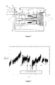
- a gas turbine engine 10 is shown in Figure 1 and comprises an air intake 12 and a propulsive fan 14 that generates two airflows A and B.
- the gas turbine engine 10 comprises, in axial flow A, an intermediate pressure compressor 16, a high pressure compressor 18, a combustor 20, a high pressure turbine 22, an intermediate pressure turbine 24, a low pressure turbine 26 and an exhaust nozzle 28.
- a nacelle 30 surrounds the gas turbine engine 10 and defines, in axial flow B, a bypass duct 32.
- An engine wash event is defined as an event in which the gas turbine engine 10 is flushed through with water or another cleaning fluid to remove at least some of the fouling material from the engine components.
- Figure 2 shows a typical plot of turbine gas temperature against time for one or more defined points in the engine cycle for many operational cycles of the engine 10. Note that the scale covers a large time period and therefore points are strongly clustered.
- the data has been processed by known methods to remove anomalous points and noise.
- the data series exhibits identifiable discontinuities which result from engine wash events, after which the turbine gas temperature drops. Between the engine wash events, the underlying trend of the data is that the turbine gas temperature increases over time.
- An equivalent plot of fuel flow against time may also be plotted.
- Figure 3 illustrates exemplary trended data in terms of fuel flow, rather than turbine gas temperature, against time.
- the discontinuous trend line 34 is plotted rather than the data points and begins at time T 1 .
- the trend line 34 is based on averages of the data points.
- the minimum and maximum points of the three portions are denoted by the letters a to g.
- the first portion 36 is between minimum point a and maximum point b
- the second portion 38 is between minimum point c and maximum point d
- the third portion 40 is between minimum point e and maximum point f.
- Engine wash events occur at times T 2 , T 3 and T 4 and cause the drop in fuel flow from, respectively, maximum point b to minimum point c, maximum point d to minimum point e, and maximum point f to minimum point g.
- the gradient of each portion of the trend line 34 is calculated by subtracting the fuel flow at the minimum point a, c, e from the fuel flow at the maximum point b, d, f and dividing the result by the time between the minimum and maximum points.
- the exemplary data comprises three portions to the trend line 34
- the length of time analysed may be fixed and the trend line 34 be based on moving averages from the data.
- the moving averages are updated and the trend line 34 will gradually alter.
- the first portion 36 of the trend line 34 will be eliminated from the data and a further portion may be added to the trend line 34 after the third portion.
- the data to be analysed may be defined as that spanning a given number of portions, for example three portions. Thus the data is updated only when a further portion is available, at which point the first portion 36 is removed from the data series.
- the increase in fuel flow over time represents a deterioration of engine performance as more fuel is used than was required previously for the same operational duty.
- the engine deterioration is comprised of two parts; firstly an amount of deterioration caused by fouling which can be recovered by engine washing and secondly an amount of underlying deterioration caused by component wear and the like which cannot be recovered.
- the gradient of underlying deterioration is calculated by averaging the gradients between the minimum points, that is averaging the gradients between minimum point a and minimum point c, minimum point c and minimum point e, and minimum point e and minimum point g.
- the underlying deterioration gradient is a measure of the rate at which that increase occurs and is shown as line 42 on Figure 3 .
- the underlying deterioration of the engine at any point in time can be calculated by multiplying the underlying deterioration gradient by the time elapsed from the beginning of the data series to the point of interest.
- the recoverable deterioration is calculated in a two-step process. First the total deterioration is determined and then the underlying deterioration is subtracted from it to leave the resultant recoverable deterioration.
- the gradient of total deterioration is calculated by averaging the gradients of the portions 36, 38, 40 of the trend line 34; thus the gradient of total deterioration is the average of G 36 , G 38 and G 40 . This is a measure of the rate of total deterioration and is shown as line 44 on Figure 3 .
- the total deterioration of the engine at any point in time is then calculated by multiplying the total deterioration gradient by the time elapsed from the beginning of the data series to the point of interest.
- the recoverable deterioration is illustrated by the vertical distance between the total deterioration line 44 and the underlying deterioration line 42.
- the total deterioration at the time of interest is read off line 44 or calculated from the steps above.
- the total deterioration is then multiplied by a pre-determined cost multiplier.
- the cost may be expressed in fuel flow, percentage increase in fuel flow, CO 2 emissions, or be a monetary value relating to any of these factors or a combination of them depending on the requirements of the specific application of the invention.
- the cost of the engine deterioration is then used as a baseline against which to measure the cost saving from different engine washing schedules.
- the method of the present invention comprises setting a number, x, of engine wash events, calculating the cost saving from that number of engine wash events, subtracting the cost of those events to give a net benefit and then comparing the cost of scheduling that number of engine wash events with the baseline cost of the engine deterioration. The method is then iterated with a different number of engine wash events and the number of events is optimised to minimise the cost or maximise the net benefit.
- the engine wash events are assumed to occur at regular time intervals and therefore the time span of the data, T 4 -T 1 , is bisected to give T 5 and engine wash events are scheduled at T 5 and T 4 .
- each engine wash event recovers all the recoverable deterioration of the engine 10.
- the fuel flow over time tracks the total deterioration line 44 from T 1 until T 5 .
- T 5 a first engine wash event occurs and the fuel flow drops to meet the underlying deterioration line 42.
- the fuel flow then increases at the total deterioration gradient, tracking a line 46 which is parallel to line 44 until T 4 when the second engine wash event occurs and the fuel flow again drops to meet the underlying deterioration line 42.
- the engine deterioration, and thus the extra fuel required due to engine component fouling, with two engine wash events is thus the area under the fuel flow line described and above the underlying deterioration line 42. This is illustrated in Figure 4 as the shaded areas 48.
- the cost of the engine deterioration with two engine wash events is the shaded areas 48 multiplied by the pre-determined cost multiplier, plus the cost of two engine wash events.
- the cost saving of the two engine wash event schedule is the baseline cost of the engine deterioration with no engine washing minus the cost of the engine deterioration with two engine wash events.
- the engine wash events are assumed to occur at regular time intervals and therefore the time span of the data, T 4 -T 1 , is divided equally into ten.
- each engine wash event recovers all the recoverable deterioration of the engine 10 so that fuel flow over time tracks the total deterioration line 44 from T 1 until the first engine wash event. At this time the fuel flow drops to meet the underlying deterioration line 42. The fuel flow then increases at the total deterioration gradient, tracking a line 46 parallel to the line 44, until the next engine wash event occurs, when the fuel flow again drops to meet the underlying deterioration line 42. This pattern is repeated for the remaining engine wash events until the final, tenth engine wash event at T 4 .
- the engine deterioration, and thus the extra fuel required due to engine component fouling, with ten engine wash events is thus the sum of the shaded areas 48, being the area between the fuel flow line described and the underlying deterioration line 42.
- the cost of the engine deterioration with ten engine wash events is the engine deterioration multiplied by the pre-determined cost multiplier, plus the cost of ten engine washes. The cost saving is this cost subtracted from the baseline cost of engine deterioration with no engine wash events.
- Figure 6 is a graph of the cost saving relative to the cost of engine deterioration with no engine wash events, for different numbers of engine wash events.
- the scheduling can be optimised mathematically or graphically by determining the largest cost saving. As illustrated in exemplary Figure 6 it can be seen that ten engine wash events is optimum because the cost saving is larger than for any other number of engine wash events plotted. Furthermore, it can be seen that the trend is that more engine wash events reduces the cost saving for numbers of engine wash events greater than ten.
- the data may also be affected by maintenance of the engine 10, for example replacement of one or more components within the engine 10 will affect its fuel flow.
- a more sophisticated embodiment of the method of the present invention will take into account variations in the data due to other factors and will thus determine the underlying deterioration gradient and total deterioration gradient accordingly.
- one or both of these gradients may change over time such that line 42 and/or line 44 may be non-linear or may be comprised of two or more contiguous but non-parallel sections. This will clearly affect the engine deterioration cost and may result in a different number of engine wash events being optimal.
- a further modification of the method of the present invention comprises varying the time interval between engine wash events so that the time intervals are irregular.
- this makes the method more lengthy to implement, because there are many more possibilities with the regularity constraint removed, it may improve the optimisation.
- Removing the regularity constraint also gives the option of tying engine wash events to times when routine maintenance and/or inspections are scheduled, although such intervals may not be optimal. This is beneficial because it is more efficient to wash the engine 10 when it has already been scheduled for the aircraft using the engine 10 to be grounded, or for the marine vessel, industrial machine or other power sink to be scheduled to use a different or no power source instead of the engine 10.
- the data from which the total deterioration gradient and the underlying deterioration gradient are calculated may be based on the actual fuel flow rate for each engine cycle or may be based on the amount of fuel used in an engine cycle averaged over the time elapsed during that cycle.
- the former is more accurate, it may be easier to obtain the latter type of data.
- the latter data will not take into account changes in engine use during a cycle, for example take off, climb and descent for an aircraft gas turbine engine 10, but will presume a constant fuel flow throughout the cycle, for example assuming that the whole cycle comprises cruise.
- the costs may be in terms of money or in other terms, such as fuel used, output power or CO 2 emitted.
- the present invention has been described in relation to a ducted fan gas turbine engine 10 for an aircraft, it is equally applicable to a gas turbine engine 10 used for any other application such as marine power, wind power or industrial power.
- the invention also finds utility for any type of engine which deteriorates over time and has recoverable deterioration which can be recovered by engine washing, for example a steam turbine or a propeller gas turbine engine.
- engine washing for example a steam turbine or a propeller gas turbine engine.
- a three-shaft engine 10 has been described the method of the present invention has equal felicity for a two-shaft gas turbine engine.
- Such washing may use water, detergent, a mixture of water and detergent, another fluid, another fluid mixed with detergent, solid particles such as nut shells or any other washing product known to the skilled reader.
- the method of the present invention is preferably encompassed in computer-implemented code and stored on a computer-readable medium. It is thus a computer-implemented method of optimising engine wash event scheduling.
- the method may be implemented on a basic computer system comprising a processing unit, memory, user interface means such as a keyboard and/or mouse, and display means.
- the method is preferably performed 'offline' on time-series data which has been measured and recorded previously. Alternatively it may be performed in 'real-time', that is at the same time that additional time-series data is measured.
- the computer may be coupled to the gas turbine engine 10.
- the computer may be an electronic engine controller or another on-board processor. Where the gas turbine engine 10 powers an aircraft, the computer may be an engine controller, a processor on-board the engine 10 or a processor on-board the aircraft.
Landscapes
- Engineering & Computer Science (AREA)
- Mechanical Engineering (AREA)
- General Engineering & Computer Science (AREA)
- Chemical & Material Sciences (AREA)
- Combustion & Propulsion (AREA)
- Combined Controls Of Internal Combustion Engines (AREA)
- Control Of Vehicle Engines Or Engines For Specific Uses (AREA)
Applications Claiming Priority (1)
| Application Number | Priority Date | Filing Date | Title |
|---|---|---|---|
| GB1208479.4A GB2502078B (en) | 2012-05-15 | 2012-05-15 | Engine wash optimisation |
Publications (1)
| Publication Number | Publication Date |
|---|---|
| EP2664747A2 true EP2664747A2 (de) | 2013-11-20 |
Family
ID=46458819
Family Applications (1)
| Application Number | Title | Priority Date | Filing Date |
|---|---|---|---|
| EP13163690.4A Withdrawn EP2664747A2 (de) | 2012-05-15 | 2013-04-15 | Triebwerkswäscheoptimierung |
Country Status (5)
| Country | Link |
|---|---|
| US (1) | US20130311060A1 (de) |
| EP (1) | EP2664747A2 (de) |
| CA (1) | CA2813216A1 (de) |
| GB (1) | GB2502078B (de) |
| SG (1) | SG195449A1 (de) |
Cited By (4)
| Publication number | Priority date | Publication date | Assignee | Title |
|---|---|---|---|---|
| EP3051075A1 (de) * | 2015-02-02 | 2016-08-03 | General Electric Company | Waschzeitgebung auf basis von turbinenbetriebsparametern |
| WO2018009734A1 (en) * | 2016-07-08 | 2018-01-11 | Ge Aviation Systems Llc | Engine performance modeling based on wash events |
| US10364699B2 (en) | 2013-10-02 | 2019-07-30 | Aerocore Technologies Llc | Cleaning method for jet engine |
| US11643946B2 (en) | 2013-10-02 | 2023-05-09 | Aerocore Technologies Llc | Cleaning method for jet engine |
Families Citing this family (3)
| Publication number | Priority date | Publication date | Assignee | Title |
|---|---|---|---|---|
| US10323539B2 (en) * | 2016-03-01 | 2019-06-18 | General Electric Company | System and method for cleaning gas turbine engine components |
| US10521981B2 (en) * | 2017-06-06 | 2019-12-31 | Ge Aviation Systems Llc | Vehicle wash assessment |
| GB2627774A (en) | 2023-03-01 | 2024-09-04 | Siemens Energy Global Gmbh & Co Kg | Methods and system for optimizing scheduling of servicing events in turbine engines |
Family Cites Families (4)
| Publication number | Priority date | Publication date | Assignee | Title |
|---|---|---|---|---|
| EP1513085A1 (de) * | 2003-09-08 | 2005-03-09 | Abb Research Ltd. | Verfahren zur Zeitplanung von Instandhaltungaktivitäten |
| JP2005133583A (ja) * | 2003-10-29 | 2005-05-26 | Hitachi Ltd | ガスタービン洗浄時期判定装置及び判定方法 |
| WO2005090764A1 (de) * | 2004-02-23 | 2005-09-29 | Siemens Aktiengesellschaft | Verfahren und vorrichtung zur diagnose einer turbinenanlage |
| JP2011529232A (ja) * | 2008-07-25 | 2011-12-01 | ユナイテッド テクノロジーズ コーポレイション | Co2削減量を特定して炭素クレジットを取得する方法 |
-
2012
- 2012-05-15 GB GB1208479.4A patent/GB2502078B/en not_active Expired - Fee Related
-
2013
- 2013-04-15 US US13/862,749 patent/US20130311060A1/en not_active Abandoned
- 2013-04-15 EP EP13163690.4A patent/EP2664747A2/de not_active Withdrawn
- 2013-04-17 SG SG2013029368A patent/SG195449A1/en unknown
- 2013-04-17 CA CA2813216A patent/CA2813216A1/en not_active Abandoned
Cited By (6)
| Publication number | Priority date | Publication date | Assignee | Title |
|---|---|---|---|---|
| US10364699B2 (en) | 2013-10-02 | 2019-07-30 | Aerocore Technologies Llc | Cleaning method for jet engine |
| US11643946B2 (en) | 2013-10-02 | 2023-05-09 | Aerocore Technologies Llc | Cleaning method for jet engine |
| EP3051075A1 (de) * | 2015-02-02 | 2016-08-03 | General Electric Company | Waschzeitgebung auf basis von turbinenbetriebsparametern |
| US9605559B2 (en) | 2015-02-02 | 2017-03-28 | General Electric Company | Wash timing based on turbine operating parameters |
| WO2018009734A1 (en) * | 2016-07-08 | 2018-01-11 | Ge Aviation Systems Llc | Engine performance modeling based on wash events |
| CN109416778A (zh) * | 2016-07-08 | 2019-03-01 | 通用电气航空系统有限责任公司 | 基于清洗事件的引擎性能建模 |
Also Published As
| Publication number | Publication date |
|---|---|
| CA2813216A1 (en) | 2013-11-15 |
| US20130311060A1 (en) | 2013-11-21 |
| GB2502078B (en) | 2015-10-14 |
| SG195449A1 (en) | 2013-12-30 |
| GB2502078A (en) | 2013-11-20 |
| GB201208479D0 (en) | 2012-06-27 |
Similar Documents
| Publication | Publication Date | Title |
|---|---|---|
| EP2664747A2 (de) | Triebwerkswäscheoptimierung | |
| Wang et al. | Review of geometric uncertainty quantification in gas turbines | |
| JP6983476B2 (ja) | 圧縮機の状態に基づく監視をするためのシステムおよび方法 | |
| US10496086B2 (en) | Gas turbine engine fleet performance deterioration | |
| Chen et al. | Fuel and emission reduction assessment for civil aircraft engine fleet on-wing washing | |
| Rezaei | A new model for the optimization of periodic inspection intervals with failure interaction: A case study for a turbine rotor | |
| Giantomassi et al. | Hidden Markov model for health estimation and prognosis of turbofan engines | |
| DE102011055474A1 (de) | System und Verfahren zur hybriden Risikomodellierung von Strömungsmaschinen | |
| EP1664953B1 (de) | Verfahren zum umsetzen einer ressource in ein produkt | |
| Zhiqi et al. | A step parameters prediction model based on transfer process neural network for exhaust gas temperature estimation after washing aero-engines | |
| EP3373233A1 (de) | Wartungsplanung zur verringerung des verschleisses eines energieerzeugungssystems | |
| US10400624B2 (en) | System and method for planning engine borescope inspections based on FOD probability estimation | |
| Enyia et al. | Industrial gas turbine on-line compressor washing for power generation | |
| CN114202823B (zh) | 预报用于预测分析的飞行器发动机操作数据的系统和方法 | |
| HK1185929A (en) | Engine wash optimisation | |
| Rao et al. | An optimal maintenance policy for compressor of a gas turbine power plant | |
| Millsaps et al. | Detection and localization of fouling in a gas turbine compressor from aerothermodynamic measurements | |
| Liu et al. | Data analytics for performance monitoring of gas turbine engine | |
| Allen et al. | Estimating recoverable performance degradation rates and optimizing maintenance scheduling | |
| CN119337099A (zh) | 一种航空发动机水洗效果评估与整机衰退预测方法及装置 | |
| Astrua et al. | Axial compressor degradation effects on heavy duty gas turbines overall performances | |
| Baker | Analysis of the sensitivity of multi-stage axial compressors to fouling at various stages | |
| Caguiat et al. | Compressor fouling testing on Rolls Royce/Allison 501-K17 and general electric LM2500 gas turbine engines | |
| Basendwah et al. | Turbine off-line water wash optimization approach for power generation | |
| Hovland et al. | Economic optimization of gas turbine compressor washing |
Legal Events
| Date | Code | Title | Description |
|---|---|---|---|
| PUAI | Public reference made under article 153(3) epc to a published international application that has entered the european phase |
Free format text: ORIGINAL CODE: 0009012 |
|
| AK | Designated contracting states |
Kind code of ref document: A2 Designated state(s): AL AT BE BG CH CY CZ DE DK EE ES FI FR GB GR HR HU IE IS IT LI LT LU LV MC MK MT NL NO PL PT RO RS SE SI SK SM TR |
|
| AX | Request for extension of the european patent |
Extension state: BA ME |
|
| REG | Reference to a national code |
Ref country code: HK Ref legal event code: DE Ref document number: 1185929 Country of ref document: HK |
|
| STAA | Information on the status of an ep patent application or granted ep patent |
Free format text: STATUS: THE APPLICATION IS DEEMED TO BE WITHDRAWN |
|
| 18D | Application deemed to be withdrawn |
Effective date: 20151103 |
|
| REG | Reference to a national code |
Ref country code: HK Ref legal event code: WD Ref document number: 1185929 Country of ref document: HK |