EP2664800B1 - Procédé de fabrication de turbine - Google Patents
Procédé de fabrication de turbine Download PDFInfo
- Publication number
- EP2664800B1 EP2664800B1 EP11855830.3A EP11855830A EP2664800B1 EP 2664800 B1 EP2664800 B1 EP 2664800B1 EP 11855830 A EP11855830 A EP 11855830A EP 2664800 B1 EP2664800 B1 EP 2664800B1
- Authority
- EP
- European Patent Office
- Prior art keywords
- welding
- positioner
- heat insulating
- insulating jacket
- assembled body
- Prior art date
- Legal status (The legal status is an assumption and is not a legal conclusion. Google has not performed a legal analysis and makes no representation as to the accuracy of the status listed.)
- Active
Links
Images



Classifications
-
- B—PERFORMING OPERATIONS; TRANSPORTING
- B23—MACHINE TOOLS; METAL-WORKING NOT OTHERWISE PROVIDED FOR
- B23K—SOLDERING OR UNSOLDERING; WELDING; CLADDING OR PLATING BY SOLDERING OR WELDING; CUTTING BY APPLYING HEAT LOCALLY, e.g. FLAME CUTTING; WORKING BY LASER BEAM
- B23K31/00—Processes relevant to this subclass, specially adapted for particular articles or purposes, but not covered by any single one of main groups B23K1/00 - B23K28/00
- B23K31/02—Processes relevant to this subclass, specially adapted for particular articles or purposes, but not covered by any single one of main groups B23K1/00 - B23K28/00 relating to soldering or welding
-
- F—MECHANICAL ENGINEERING; LIGHTING; HEATING; WEAPONS; BLASTING
- F04—POSITIVE - DISPLACEMENT MACHINES FOR LIQUIDS; PUMPS FOR LIQUIDS OR ELASTIC FLUIDS
- F04D—NON-POSITIVE-DISPLACEMENT PUMPS
- F04D29/00—Details, component parts, or accessories
- F04D29/02—Selection of particular materials
- F04D29/023—Selection of particular materials especially adapted for elastic fluid pumps
-
- F—MECHANICAL ENGINEERING; LIGHTING; HEATING; WEAPONS; BLASTING
- F04—POSITIVE - DISPLACEMENT MACHINES FOR LIQUIDS; PUMPS FOR LIQUIDS OR ELASTIC FLUIDS
- F04D—NON-POSITIVE-DISPLACEMENT PUMPS
- F04D29/00—Details, component parts, or accessories
- F04D29/26—Rotors specially for elastic fluids
- F04D29/28—Rotors specially for elastic fluids for centrifugal or helico-centrifugal pumps for radial-flow or helico-centrifugal pumps
- F04D29/284—Rotors specially for elastic fluids for centrifugal or helico-centrifugal pumps for radial-flow or helico-centrifugal pumps for compressors
-
- B—PERFORMING OPERATIONS; TRANSPORTING
- B23—MACHINE TOOLS; METAL-WORKING NOT OTHERWISE PROVIDED FOR
- B23K—SOLDERING OR UNSOLDERING; WELDING; CLADDING OR PLATING BY SOLDERING OR WELDING; CUTTING BY APPLYING HEAT LOCALLY, e.g. FLAME CUTTING; WORKING BY LASER BEAM
- B23K2101/00—Articles made by soldering, welding or cutting
- B23K2101/001—Turbines
-
- F—MECHANICAL ENGINEERING; LIGHTING; HEATING; WEAPONS; BLASTING
- F05—INDEXING SCHEMES RELATING TO ENGINES OR PUMPS IN VARIOUS SUBCLASSES OF CLASSES F01-F04
- F05D—INDEXING SCHEME FOR ASPECTS RELATING TO NON-POSITIVE-DISPLACEMENT MACHINES OR ENGINES, GAS-TURBINES OR JET-PROPULSION PLANTS
- F05D2230/00—Manufacture
- F05D2230/20—Manufacture essentially without removing material
- F05D2230/23—Manufacture essentially without removing material by permanently joining parts together
- F05D2230/232—Manufacture essentially without removing material by permanently joining parts together by welding
-
- Y—GENERAL TAGGING OF NEW TECHNOLOGICAL DEVELOPMENTS; GENERAL TAGGING OF CROSS-SECTIONAL TECHNOLOGIES SPANNING OVER SEVERAL SECTIONS OF THE IPC; TECHNICAL SUBJECTS COVERED BY FORMER USPC CROSS-REFERENCE ART COLLECTIONS [XRACs] AND DIGESTS
- Y10—TECHNICAL SUBJECTS COVERED BY FORMER USPC
- Y10T—TECHNICAL SUBJECTS COVERED BY FORMER US CLASSIFICATION
- Y10T29/00—Metal working
- Y10T29/49—Method of mechanical manufacture
- Y10T29/49316—Impeller making
-
- Y—GENERAL TAGGING OF NEW TECHNOLOGICAL DEVELOPMENTS; GENERAL TAGGING OF CROSS-SECTIONAL TECHNOLOGIES SPANNING OVER SEVERAL SECTIONS OF THE IPC; TECHNICAL SUBJECTS COVERED BY FORMER USPC CROSS-REFERENCE ART COLLECTIONS [XRACs] AND DIGESTS
- Y10—TECHNICAL SUBJECTS COVERED BY FORMER USPC
- Y10T—TECHNICAL SUBJECTS COVERED BY FORMER US CLASSIFICATION
- Y10T29/00—Metal working
- Y10T29/49—Method of mechanical manufacture
- Y10T29/49826—Assembling or joining
- Y10T29/49947—Assembling or joining by applying separate fastener
- Y10T29/49966—Assembling or joining by applying separate fastener with supplemental joining
- Y10T29/49968—Metal fusion joining
Definitions
- the present invention relates to a method of manufacturing an impeller (a rotary wing) for use in a centrifugal compressor or other rotating machines and, in more detail, to a method of joining a plurality of components configuring an impeller by welding.
- an impeller 10 for an centrifugal compressor is configured of a hub 11 with one surface fixed to a rotation main axis of the centrifugal compressor for rotation being curved to be thinner toward its tip, a shroud 12 in the shape of facing the curved surface of the hub 11, and a plurality of blades 13 provided so as to partition a curved surface between the hub 11 and the shroud 12 in a swirl shape.
- a flow path 14 for compressed gas is formed.
- Examples of the impeller 10 include one called a three-piece type in which the hub 11, the shroud 12, and the blades 13 are individually produced and joined to one another and one called a two-piece type in which the shroud 12 and the blades 13 (or the hub 11 and the blades 13) are integrally fabricated and are joined to the hub 11 (or the shroud 12) fabricated separately therefrom.
- joining is made by welding or brazing. Whether joining is made by welding or brazing is determined based on the size, strength, and others of the impeller 10.
- the impeller material is required to be kept at a predetermined temperature or higher.
- preheating is performed to heat the impeller before welding starts.
- the temperature may be decreased during welding to cause cold cracking.
- a positioner capable of changing the orientation of the impeller is used to facilitate a welding torch to access a required position. Welding is performed with the impeller mounted on this positioner. Thus, by performing a welding operation with the impeller material mounted on a positioner having a heating function, the temperature of the impeller material during welding is kept.
- the present invention is made based on the problems described above, and has an object of providing an impeller welding method capable of avoiding a decrease in temperature when a worker joins by welding to make an impeller and also reducing work load.
- An impeller to which the invention is directed includes a hub, a shroud placed to face the hub, and a plurality of blades provided between the hub and the shroud.
- a flow path leading from an inflow port to a discharge port is provided between the hub and the shroud.
- the hub and the shroud are joined by welding.
- an assembled body with the hub and the shroud placed on top of each other is in an upright state in which the inflow port is oriented upward and the hub is placed to face a mount surface. And, in the present invention, welding is performed with the assembled body except an open region and the inflow port that are required for welding being covered with a heat insulating jacket.
- the heat insulating jacket is moved with respect to the assembled body to form a new open region for next welding.
- the heat insulating jacket may be integrally formed (hereinafter, an integral jacket), but is preferably formed of a plurality of divisional segment jackets.
- the open region can be formed by not placing a segment jacket on a position where an open region is to be formed.
- the open region can also be formed by providing a window penetrating through both of front and rear surfaces to both of the integral jacket and the segment jackets at a position that is supposed to correspond to the open region.
- positions where an open region is to be formed can be narrowed to a specific region required for welding. This is advantageous for preventing a decrease in temperature during welding.
- the positioner for this purpose is configured of a positioner body and a mount table rotatably placed relative to the positioner body. While the assembled body is mounted on the mount table, the assembled body is covered with the heat insulating jacket fixed to the positioner body.
- the mount table is rotated after welding for one open region is completed, the assembled body rotates (moves) according to the rotation of the mount table.
- the heat insulating jacket is fixed to the positioner body, the assembled body and the heat insulating jacket relatively move. As a result, a new open region can be formed while manual work is minimized.
- any method can be used as a method of fixing the heat insulating jacket to the positioner body, it is preferable to use a fastener such as a bolt that allows easy attachment and removal of the heat insulating jacket.
- the heat insulating jacket covering the assembled body is the segment jackets
- adjacent ones of the segment jackets are preferably connected with a connecting member. This is to avoid the segment jackets from curling up in accordance with the rotation of the mount table and becoming unable to cover a necessary position of the assembled body.
- Any connecting member can be used, such as a wire.
- the present invention since a worker makes an impeller by welding while covering the assembled body with the heat insulating jacket, a decrease in temperature of the assembled body can be avoided. Also, since the worker is not required to wear a heavy heat insulation equipment, work load on the worker can be reduced.
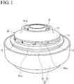
- welding is performed with an impeller 10 mounted on a positioner 20.
- the impeller 10 includes a hub 11, a shroud 12 placed to face the hub 11, and a plurality of blades 13 provided between the hub 11 and the shroud 12.
- a flow path 14 leading from an inflow port 14 IN to a discharge port 14 OUT is provided between the hub 11 and the shroud 12.
- a fluid to be compressed flows in from the inflow port 14 IN , and is discharged from the discharge port 14 OUT .
- the blades 13 are formed integrally with the hub 11 or the shroud 12.
- the blades 13 and the shroud 12 are joined by welding.
- the blades 13 and the hub 11 are joined by welding.
- the hub 11 and the shroud 12 are placed on top of each other in an upright state in which the hub 11 faces a mount table 22 (a mount surface) of the positioner 20 to form the impeller 10.
- the impeller 10 has the inflow port 14 IN oriented upward.
- the impeller 10 is a precursor until welding ends to complete the impeller 10, this precursor is hereinafter referred to as an assembled body and is provided with the same reference numeral as that of the impeller 10. Also, preliminary welding may be performed to prevent a positional misalignment between the hub 11 and the shroud 12 when the assembled body is configured.
- the posture of the assembled body 10 can be changed during welding.
- the positioner 20 includes a positioner body 21 and a mount table 22.
- the positioner body 21 is set to be able to swing in a three-dimensional direction by a mechanism not shown in the drawings. The worker adjusts the posture of the positioner body 21 so as to facilitate the welding operation.
- the mount table 22 is rotatably held with respect to the positioner body 21. Therefore, the assembled body 10 can be rotated via the mount table 22 independently of the positioner body 21.
- the positioner 20 includes heating means (not shown) such as a heater in the positioner body 21 or the mount table 22.
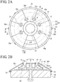
- welding is performed with the assembled body 10 being covered with a heat insulating jacket. Description is made below with reference to FIG. 2 .
- the heat insulating jacket Since the assembled body 10 has a ring shape in a planar view, if the heat insulating jacket is integrally fabricated, the heat insulating jacket has a ring shape. In the present embodiment, however, a plurality of segment jackets (heat insulating jackets) 30a to 30g obtained by dividing the ring shape in a circumferential direction into plural portions are used. Since the ring shape is divided into eight in the present embodiment, the segment jackets 30a to 30g each have a fan shape with a central angle of 22.5 degrees. The number of division, eight, is merely an example and, needless to say, another number of division can be adopted. The present invention also includes a mode in which the heat insulating jacket is integrally formed.
- the segment jackets 30a to 30g are spread in a circumferential direction over the assembled body 10 without a gap to cover the assembled body 10 with the segment jackets 30a to 30g.
- segment jackets 30a to 30g each have a central angle of 22.5 degrees, a region corresponding to one segment jacket cannot be covered with a segment jacket. Welding is performed correspondingly to an open region OP not covered with this heat insulating jacket (the segment jackets 30a to 30g). From the open region OP, the discharge port 14 OUT (the flow path 14) of the assembled body 10 is exposed, where a welding torch (not shown) is inserted to be able to weld the blades 13 and the hub 11 (or the shroud 12).
- the open region OP defines a range capable of successive welding at a time.
- an inner diameter side of the hub 11 of the assembled body 10 is also covered with a circular heat insulating jacket 31.
- the heat insulating jacket 31 is supported by a support 23.
- the inflow port 14 IN is open without being covered with a heat insulating jacket. That is, in a planar view, except the open region OP and the inflow port 14 IN , the assembled body 10 is covered with the heat insulating jacket (the segment jackets 30a to 30g) and the heat insulating jacket 31.
- the reason for excluding the inflow port 14 IN from targets for covering with a heat insulating jacket is as follows. Welding is performed with the welding torch inserted from the discharge port 14 OUT . For appropriate welding, a brightness with which a position to be welded is viewable is required. Thus, to ensure the brightness required for the position to be welded by letting light in from the inflow port 14 IN , the inflow port 14 IN is not covered with a heat insulating jacket. Also, while most of the welding of the blades 13 and the hub 11 (or the shroud 12) can be performed by inserting the welding torch from the discharge port 14 OUT , it may be sometimes appropriate to insert the welding torch from the inflow port 14 IN . In consideration of such case, the inflow port 14 IN is open.
- segment jackets 30a to 30g are fixed to an outer perimeter of the positioner body 21 with fasteners 33 such as bolts, portions covering the assembled body 10 are not fixed to the assembled body 10. That is, the segment jackets 30a to 30g each have a lower end fixed but other portions simply placed on the assembled body 10.
- the bolts as fixing means to the positioner body 21 are merely an example, and another fixing means can be used.
- cramping members can be provided to the positioner body 21 to cramp the segment jackets 30a to 30g.
- adjacent ones of the segment jackets 30a to 30g are connected to each other with a connector 32, thereby increasing stiffness as a whole.
- Any mode of the connector 32 can be used, and any of various modes can be applied, such as a mode in which a hook is provided to one side and an engaging hole for this hook is provided to the other side.
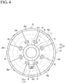
- FIGS. 3A to 3D When welding for one open region OP is completed, the worker goes away from the assembled body 10 mounted on the positioner 20 and rotates the mount table 22 of the positioner 20.
- the mount table 22 is rotated by an angle corresponding to the central angle (22.5 degrees) of one segment jacket 30a (to 30g), which state is shown in FIGS. 3A to 3D .
- the segment jackets 30a to 30g are moved in FIGS. 3A to 3D.
- FIG. 3A to FIG. 3D each show the state in which the segment jackets 30a to 30g go round, and the segment jackets 30a to 30g make a rotational movement twice each between FIG. 3A and FIG. 3B, FIG. 3B and FIG. 3C, and FIG. 3C and FIG. 3D .
- the segment jackets 30a to 30g each have a lower end fixed to the positioner body 21 and are simply mounted on the assembled body 10. Therefore, even the mount table 22 is rotated, the segment jackets 30a to 30g are kept fixed, and only the assembled body 10 (the mount table 22) is rotated. Therefore, to an open region between the segment jacket 30a and the segment jacket 30g, the discharge port 14 OUT of a portion that is not yet a target for welding comes. In this manner, by forming a new open region OP (discharge port 14 OUT ), the next welding is performed. Then, the procedure described above is repeated until the assembled body 10 rotates 360 degrees.
- welding is performed with most of the assembled body 10 being covered with the segment jackets 30a to 30g. Therefore, according to the present embodiment, heat radiation from the assembled body 10 during welding can be inhibited. Therefore, a decrease in temperature of the assembled body 10 during welding can be prevented. Also, since radiant heat received by the worker is also reduced, the worker is not required to wear a heavy heat insulation equipment. In particular, in the present embodiment, to move the segment jackets 30a to 30g with respect to the assembled body 10, all the worker has to do is to simply move the mount table 22 of the positioner 22. Therefore, the work load on the worker is extremely light.
- FIG. 6 shows results obtained by measuring temperatures during welding in the case of welding by using the segment jackets 30a to 30g (disk temperature with a heat insulator) and in the case of welding without using the segment jackets 30a to 30g (disk temperature without a heat insulator).
- the temperature during welding can be kept at a predetermined temperature indicated by a broken line or higher.
- the open region OP can be formed by providing a window W penetrating through front and rear surfaces to a segment jacket 30h.
- segment jackets 30a to 30g are connected with the connector 32, thereby increasing stiffness as a whole. Therefore, it is possible to prevent the segment jackets 30a to 30g from mutually causing a positional misalignment and curling up in accordance with the rotation of the assembled body 10.
- the material configuring the heat insulating jacket is not restrictive, and any of various known materials can be used.
- a fireproof sheet made of fireproof fiber such as ceramic fiber or glass fiber can be used for the heat insulating jacket.
- segment jackets obtained by division in a circumferential direction has been described in the present embodiment, the present invention is not limited to this, and segment jackets obtained by division in a diameter direction can also be used.
- an integral jacket covering the assembled body 10 except the open region OP and the inflow port 14 IN can be used in the present invention.
- the present invention is not limited to this, and the open region OP can be moved by the worker moving the heat insulating jacket with a manual operation.
- the present invention is not limited to this.
- the present invention can be similarly applied to the impeller 10 of the three-piece type in which the hub 11, the shroud 12, and the blades 13 are individually produced and joined together.
- the welding in the present embodiment can be applied in two stages as described below.
- welding can be performed similarly to the present embodiment with the assembled body 10 in which the hub 11 and the shroud 12 subjected to the first stage described above are placed on top of each other via the blades 13 is covered with the heat insulating jacket except the open region OP and the inflow port 14 IN required for welding.
Landscapes
- Engineering & Computer Science (AREA)
- Mechanical Engineering (AREA)
- General Engineering & Computer Science (AREA)
- Structures Of Non-Positive Displacement Pumps (AREA)
- Butt Welding And Welding Of Specific Article (AREA)
Claims (9)
- Procédé de fabrication de rouet selon lequel un rouet inclut un moyeu (11), un carénage (12) qui est positionné de manière à ce qu'il fasse face au moyeu (11) et une pluralité de palettes (13) qui sont prévues entre le moyeu (11) et le carénage (12), le rouet (10) comportant une voie d'écoulement (14) qui va depuis un orifice d'écoulement d'entrée (14IN) jusqu'à un orifice de décharge (14OUT) qui est formé entre le moyeu (11) et le carénage (12), un fluide s'écoulant depuis l'orifice d'écoulement d'entrée en direction de l'orifice de décharge, le moyeu (11) et le carénage (12) étant joints par soudage ; dans lequel :pendant le soudage, un corps assemblé qui comporte le moyeu (11) et le carénage (12) qui sont positionnés sur le sommet l'un de l'autre est dans un état vertical dans lequel l'orifice d'écoulement d'entrée (14IN) est orienté vers le haut et le moyeu (11) est positionné de manière à ce qu'il fasse face à une surface de montage (22) ;caractérisé en ce que :le soudage est réalisé sur le corps assemblé tandis qu'une enveloppe thermo-isolante (30, 31) recouvre le corps assemblé à l'exception d'une région ouverte (OP) et de l'orifice d'écoulement d'entrée (14IN) qui sont requis pour le soudage ; etlorsque le soudage de la région ouverte (OP) est terminé, l'enveloppe thermo-isolante (30, 31) est déplacée par rapport au corps assemblé de manière à former une nouvelle région ouverte pour un soudage suivant.
- Procédé de fabrication de rouet selon la revendication 1, dans lequel :
l'enveloppe thermo-isolante (30, 31) est formée à partir d'une pluralité d'enveloppes sous forme de segments divisionnaires (30a-30h). - Procédé de fabrication de rouet selon la revendication 1, dans lequel :
une fenêtre qui pénètre à travers à la fois de surfaces avant et arrière est prévue sur l'enveloppe thermo-isolante (30, 31) au niveau d'une position qui est supposée correspondre à la région ouverte (OP). - Procédé de fabrication de rouet selon la revendication 2, dans lequel :
une fenêtre qui pénètre à travers à la fois de surfaces avant et arrière est prévue sur l'enveloppe thermo-isolante (30, 31) au niveau d'une position qui est supposée correspondre à la région ouverte (OP). - Procédé de fabrication de rouet selon la revendication 1, dans lequel :un moyen de positionnement (20) est utilisé, le moyen de positionnement (20) incluant un corps de moyen de positionnement (21) et une table de montage (22) qui est positionnée à rotation par rapport au corps de moyen de positionnement (21) ;le corps assemblé est monté sur la table de montage (22) et le soudage est réalisé tandis que le corps assemblé est recouvert de l'enveloppe thermo-isolante (30, 31) qui est fixée au corps de moyen de positionnement (21) ; etaprès que le soudage pour la région ouverte est terminé, la table de montage (22) est entraînée en rotation de manière à déplacer de façon relative le corps assemblé et l'enveloppe thermo-isolante de manière à former la nouvelle région ouverte.
- Procédé de fabrication de rouet selon la revendication 2, dans lequel :un moyen de positionnement (20) est utilisé, le moyen de positionnement (20) incluant un corps de moyen de positionnement (21) et une table de montage (22) qui est positionnée à rotation par rapport au corps de moyen de positionnement (21) ;le corps assemblé est monté sur la table de montage (22) et le soudage est réalisé tandis que le corps assemblé est recouvert de l'enveloppe thermo-isolante (30, 31) qui est fixée au corps de moyen de positionnement (21) ; etaprès que le soudage pour la région ouverte est terminé, la table de montage (22) est entraînée en rotation de manière à déplacer de façon relative le corps assemblé et l'enveloppe thermo-isolante de manière à former la nouvelle région ouverte.
- Procédé de fabrication de rouet selon la revendication 3, dans lequel :un moyen de positionnement (20) est utilisé, le moyen de positionnement (20) incluant un corps de moyen de positionnement (21) et une table de montage (22) qui est positionnée à rotation par rapport au corps de moyen de positionnement (21) ;le corps assemblé est monté sur la table de montage (22) et le soudage est réalisé tandis que le corps assemblé est recouvert de l'enveloppe thermo-isolante (30, 31) qui est fixée au corps de moyen de positionnement (21) ; etaprès que le soudage pour la région ouverte est terminé, la table de montage (22) est entraînée en rotation de manière à déplacer de façon relative le corps assemblé et l'enveloppe thermo-isolante de manière à former la nouvelle région ouverte.
- Procédé de fabrication de rouet selon la revendication 2, dans lequel :
lorsque l'enveloppe thermo-isolante (30, 31) qui recouvre le corps assemblé est constituée par les enveloppes sous forme de segments, celles adjacentes des enveloppes sous forme de segments (30a-30h) sont connectées avec un élément de connexion (32). - Procédé de fabrication de rouet selon la revendication 4, dans lequel :
lorsque l'enveloppe thermo-isolante qui recouvre le corps assemblé est constituée par les enveloppes sous forme de segments (30, 31), celles adjacentes des enveloppes sous forme de segments (30a-30h) sont connectées avec un élément de connexion.
Applications Claiming Priority (2)
| Application Number | Priority Date | Filing Date | Title |
|---|---|---|---|
| JP2011005402 | 2011-01-14 | ||
| PCT/JP2011/005953 WO2012095908A1 (fr) | 2011-01-14 | 2011-10-25 | Procédé de fabrication de turbine |
Publications (3)
| Publication Number | Publication Date |
|---|---|
| EP2664800A1 EP2664800A1 (fr) | 2013-11-20 |
| EP2664800A4 EP2664800A4 (fr) | 2017-07-05 |
| EP2664800B1 true EP2664800B1 (fr) | 2019-05-08 |
Family
ID=46506840
Family Applications (1)
| Application Number | Title | Priority Date | Filing Date |
|---|---|---|---|
| EP11855830.3A Active EP2664800B1 (fr) | 2011-01-14 | 2011-10-25 | Procédé de fabrication de turbine |
Country Status (5)
| Country | Link |
|---|---|
| US (1) | US8590150B2 (fr) |
| EP (1) | EP2664800B1 (fr) |
| JP (1) | JP5439609B2 (fr) |
| CN (1) | CN102959248B (fr) |
| WO (1) | WO2012095908A1 (fr) |
Families Citing this family (8)
| Publication number | Priority date | Publication date | Assignee | Title |
|---|---|---|---|---|
| CN103394880B (zh) * | 2013-08-15 | 2015-12-09 | 沈阳三科水力机械制造有限公司 | 大型循环泵叶轮摆焊成型方法 |
| CN104564799B (zh) * | 2014-12-30 | 2017-03-08 | 张家港金汇风机制造有限公司 | 一种加强型叶轮 |
| US11002291B2 (en) | 2016-03-30 | 2021-05-11 | Mitsubishi Heavy Industries Engine & Turbocharger, Ltd. | Compressor impeller |
| CN113020828B (zh) * | 2021-02-03 | 2022-07-08 | 武汉船用机械有限责任公司 | 前导管的制造方法 |
| WO2022187038A1 (fr) * | 2021-03-05 | 2022-09-09 | Danfoss A/S | Techniques d'application d'un matériau de brasage pour former une roue carénée |
| CN115415727A (zh) * | 2022-09-02 | 2022-12-02 | 重庆通用工业(集团)有限责任公司 | 一种透平机械三元流叶轮焊接变位装置及方法 |
| CN118578070B (zh) * | 2024-07-02 | 2026-06-09 | 上海东心生物医疗科技有限公司 | 离心式血泵用闭式螺旋线形叶轮的制造工艺 |
| CN119703560B (zh) * | 2024-12-27 | 2025-11-18 | 赛麟重工江苏有限公司 | 水泵加工用叶轮拼焊装置及其使用方法 |
Family Cites Families (9)
| Publication number | Priority date | Publication date | Assignee | Title |
|---|---|---|---|---|
| JPS5428006A (en) * | 1977-08-03 | 1979-03-02 | Hitachi Ltd | Method for manufacturing closed impeller |
| JPS6448682A (en) * | 1987-08-18 | 1989-02-23 | Mitsubishi Heavy Ind Ltd | Electron beam welding method for impeller |
| JP3400720B2 (ja) | 1998-07-28 | 2003-04-28 | 株式会社日立製作所 | ろう付け装置 |
| US6079613A (en) * | 1998-10-15 | 2000-06-27 | Plumber's Guardian, Inc. | Heat suppressing wrap |
| JP2004036485A (ja) * | 2002-07-03 | 2004-02-05 | Hitachi Industries Co Ltd | 圧縮機用羽根車の製造方法及び圧縮機用羽根車 |
| US7247000B2 (en) * | 2004-08-30 | 2007-07-24 | Honeywell International, Inc. | Weld shielding device for automated welding of impellers and blisks |
| US7425118B2 (en) * | 2005-10-27 | 2008-09-16 | Honeywell International Inc. | Mask for shielding impellers and blisks during automated welding |
| JP4981513B2 (ja) | 2007-05-08 | 2012-07-25 | 三菱重工業株式会社 | 溶接方法、溶接装置 |
| JP5131237B2 (ja) * | 2009-03-27 | 2013-01-30 | 株式会社日立プラントテクノロジー | 羽根車およびその製造方法 |
-
2011
- 2011-10-25 EP EP11855830.3A patent/EP2664800B1/fr active Active
- 2011-10-25 US US13/805,021 patent/US8590150B2/en active Active
- 2011-10-25 JP JP2012552537A patent/JP5439609B2/ja active Active
- 2011-10-25 WO PCT/JP2011/005953 patent/WO2012095908A1/fr not_active Ceased
- 2011-10-25 CN CN201180030651.XA patent/CN102959248B/zh active Active
Non-Patent Citations (1)
| Title |
|---|
| None * |
Also Published As
| Publication number | Publication date |
|---|---|
| EP2664800A1 (fr) | 2013-11-20 |
| US20130140349A1 (en) | 2013-06-06 |
| EP2664800A4 (fr) | 2017-07-05 |
| WO2012095908A1 (fr) | 2012-07-19 |
| CN102959248A (zh) | 2013-03-06 |
| JPWO2012095908A1 (ja) | 2014-06-09 |
| US8590150B2 (en) | 2013-11-26 |
| CN102959248B (zh) | 2015-09-30 |
| JP5439609B2 (ja) | 2014-03-12 |
Similar Documents
| Publication | Publication Date | Title |
|---|---|---|
| US8590150B2 (en) | Impeller manufacturing method | |
| EP3305464B1 (fr) | Système et procédé de scellement des canaux internes définis dans un composant | |
| EP3015648B1 (fr) | Composant refroidi | |
| CN104279006B (zh) | 涡轮构件及其组装方法 | |
| US9523286B2 (en) | Vane segment and axial-flow fluid machine including the same | |
| US20150128602A1 (en) | Heat shield for a gas turbine combustion chamber | |
| EP3170978B1 (fr) | Plate-forme, aube rotorique et procédé de manufacture associés | |
| EP2353763A1 (fr) | Procédé de fabrication de composant pour gaz chaud avec un canal de refroidissement par brasage d'un élément fritté sur une base ; composant à gaz chaud correspondant | |
| EP2559855A2 (fr) | Aube de turbine avec trous de refroidissement par film et procédé de sa fabrication | |
| EP3012531B1 (fr) | Trous traversants hybrides et trous inclinés pour refroidissement d'oeillet de chambre de combustion | |
| US11927110B2 (en) | Component for a turbine engine with a cooling hole | |
| JP6798796B2 (ja) | 表面冷却チャンネルを有するタービン構成要素及びその形成方法 | |
| EP3284908B1 (fr) | Aube à parois multiples avec circuit de refroidissement | |
| EP3789131A1 (fr) | Procédé de formation de composants de moteur à turbine à gaz | |
| EP3287619A1 (fr) | Mécanisme à buse variable et turbocompresseur à géométrie variable | |
| US20170002663A1 (en) | Gas turbine engine airfoil squealer pocket cooling hole configuration | |
| US20130251515A1 (en) | Thermal isolation apparatus | |
| EP2943657B1 (fr) | Aube de guidage d'entrée structurale composite matriciel organique pour moteur à turbine | |
| JP2015528876A (ja) | 案内翼を製造するための方法および案内翼 | |
| CN107201920A (zh) | 具有膜孔的用于涡轮发动机的部件 | |
| US10697309B2 (en) | Platform cover plates for gas turbine engine components | |
| EP3279434B1 (fr) | Composant refroidi d'un moteur de turbine à gaz avec un insert | |
| CN110630337A (zh) | 重叠的靠近表面的冷却通道 | |
| WO2004090423A1 (fr) | Element d'ecran thermique | |
| EP3186483B1 (fr) | Procédé de fabrication d'un ensemble turbine |
Legal Events
| Date | Code | Title | Description |
|---|---|---|---|
| PUAI | Public reference made under article 153(3) epc to a published international application that has entered the european phase |
Free format text: ORIGINAL CODE: 0009012 |
|
| 17P | Request for examination filed |
Effective date: 20121221 |
|
| AK | Designated contracting states |
Kind code of ref document: A1 Designated state(s): AL AT BE BG CH CY CZ DE DK EE ES FI FR GB GR HR HU IE IS IT LI LT LU LV MC MK MT NL NO PL PT RO RS SE SI SK SM TR |
|
| DAX | Request for extension of the european patent (deleted) | ||
| RA4 | Supplementary search report drawn up and despatched (corrected) |
Effective date: 20170602 |
|
| RIC1 | Information provided on ipc code assigned before grant |
Ipc: F04D 29/02 20060101ALI20170529BHEP Ipc: B23K 101/00 20060101ALI20170529BHEP Ipc: B23K 31/00 20060101ALI20170529BHEP Ipc: F04D 29/28 20060101AFI20170529BHEP Ipc: B23K 9/00 20060101ALI20170529BHEP Ipc: B23K 31/02 20060101ALI20170529BHEP |
|
| GRAP | Despatch of communication of intention to grant a patent |
Free format text: ORIGINAL CODE: EPIDOSNIGR1 |
|
| STAA | Information on the status of an ep patent application or granted ep patent |
Free format text: STATUS: GRANT OF PATENT IS INTENDED |
|
| INTG | Intention to grant announced |
Effective date: 20190121 |
|
| GRAS | Grant fee paid |
Free format text: ORIGINAL CODE: EPIDOSNIGR3 |
|
| GRAA | (expected) grant |
Free format text: ORIGINAL CODE: 0009210 |
|
| STAA | Information on the status of an ep patent application or granted ep patent |
Free format text: STATUS: THE PATENT HAS BEEN GRANTED |
|
| AK | Designated contracting states |
Kind code of ref document: B1 Designated state(s): AL AT BE BG CH CY CZ DE DK EE ES FI FR GB GR HR HU IE IS IT LI LT LU LV MC MK MT NL NO PL PT RO RS SE SI SK SM TR |
|
| REG | Reference to a national code |
Ref country code: GB Ref legal event code: FG4D |
|
| REG | Reference to a national code |
Ref country code: DE Ref legal event code: R082 Ref document number: 602011058889 Country of ref document: DE Representative=s name: KOHLER SCHMID MOEBUS PATENTANWAELTE PARTNERSCH, DE |
|
| REG | Reference to a national code |
Ref country code: CH Ref legal event code: EP Ref country code: AT Ref legal event code: REF Ref document number: 1130563 Country of ref document: AT Kind code of ref document: T Effective date: 20190515 |
|
| REG | Reference to a national code |
Ref country code: IE Ref legal event code: FG4D |
|
| REG | Reference to a national code |
Ref country code: DE Ref legal event code: R096 Ref document number: 602011058889 Country of ref document: DE |
|
| REG | Reference to a national code |
Ref country code: NL Ref legal event code: MP Effective date: 20190508 |
|
| REG | Reference to a national code |
Ref country code: LT Ref legal event code: MG4D |
|
| PG25 | Lapsed in a contracting state [announced via postgrant information from national office to epo] |
Ref country code: HR Free format text: LAPSE BECAUSE OF FAILURE TO SUBMIT A TRANSLATION OF THE DESCRIPTION OR TO PAY THE FEE WITHIN THE PRESCRIBED TIME-LIMIT Effective date: 20190508 Ref country code: LT Free format text: LAPSE BECAUSE OF FAILURE TO SUBMIT A TRANSLATION OF THE DESCRIPTION OR TO PAY THE FEE WITHIN THE PRESCRIBED TIME-LIMIT Effective date: 20190508 Ref country code: NO Free format text: LAPSE BECAUSE OF FAILURE TO SUBMIT A TRANSLATION OF THE DESCRIPTION OR TO PAY THE FEE WITHIN THE PRESCRIBED TIME-LIMIT Effective date: 20190808 Ref country code: NL Free format text: LAPSE BECAUSE OF FAILURE TO SUBMIT A TRANSLATION OF THE DESCRIPTION OR TO PAY THE FEE WITHIN THE PRESCRIBED TIME-LIMIT Effective date: 20190508 Ref country code: SE Free format text: LAPSE BECAUSE OF FAILURE TO SUBMIT A TRANSLATION OF THE DESCRIPTION OR TO PAY THE FEE WITHIN THE PRESCRIBED TIME-LIMIT Effective date: 20190508 Ref country code: ES Free format text: LAPSE BECAUSE OF FAILURE TO SUBMIT A TRANSLATION OF THE DESCRIPTION OR TO PAY THE FEE WITHIN THE PRESCRIBED TIME-LIMIT Effective date: 20190508 Ref country code: AL Free format text: LAPSE BECAUSE OF FAILURE TO SUBMIT A TRANSLATION OF THE DESCRIPTION OR TO PAY THE FEE WITHIN THE PRESCRIBED TIME-LIMIT Effective date: 20190508 Ref country code: PT Free format text: LAPSE BECAUSE OF FAILURE TO SUBMIT A TRANSLATION OF THE DESCRIPTION OR TO PAY THE FEE WITHIN THE PRESCRIBED TIME-LIMIT Effective date: 20190908 Ref country code: FI Free format text: LAPSE BECAUSE OF FAILURE TO SUBMIT A TRANSLATION OF THE DESCRIPTION OR TO PAY THE FEE WITHIN THE PRESCRIBED TIME-LIMIT Effective date: 20190508 |
|
| PG25 | Lapsed in a contracting state [announced via postgrant information from national office to epo] |
Ref country code: GR Free format text: LAPSE BECAUSE OF FAILURE TO SUBMIT A TRANSLATION OF THE DESCRIPTION OR TO PAY THE FEE WITHIN THE PRESCRIBED TIME-LIMIT Effective date: 20190809 Ref country code: BG Free format text: LAPSE BECAUSE OF FAILURE TO SUBMIT A TRANSLATION OF THE DESCRIPTION OR TO PAY THE FEE WITHIN THE PRESCRIBED TIME-LIMIT Effective date: 20190808 Ref country code: LV Free format text: LAPSE BECAUSE OF FAILURE TO SUBMIT A TRANSLATION OF THE DESCRIPTION OR TO PAY THE FEE WITHIN THE PRESCRIBED TIME-LIMIT Effective date: 20190508 Ref country code: RS Free format text: LAPSE BECAUSE OF FAILURE TO SUBMIT A TRANSLATION OF THE DESCRIPTION OR TO PAY THE FEE WITHIN THE PRESCRIBED TIME-LIMIT Effective date: 20190508 |
|
| REG | Reference to a national code |
Ref country code: AT Ref legal event code: MK05 Ref document number: 1130563 Country of ref document: AT Kind code of ref document: T Effective date: 20190508 |
|
| PG25 | Lapsed in a contracting state [announced via postgrant information from national office to epo] |
Ref country code: EE Free format text: LAPSE BECAUSE OF FAILURE TO SUBMIT A TRANSLATION OF THE DESCRIPTION OR TO PAY THE FEE WITHIN THE PRESCRIBED TIME-LIMIT Effective date: 20190508 Ref country code: DK Free format text: LAPSE BECAUSE OF FAILURE TO SUBMIT A TRANSLATION OF THE DESCRIPTION OR TO PAY THE FEE WITHIN THE PRESCRIBED TIME-LIMIT Effective date: 20190508 Ref country code: SK Free format text: LAPSE BECAUSE OF FAILURE TO SUBMIT A TRANSLATION OF THE DESCRIPTION OR TO PAY THE FEE WITHIN THE PRESCRIBED TIME-LIMIT Effective date: 20190508 Ref country code: AT Free format text: LAPSE BECAUSE OF FAILURE TO SUBMIT A TRANSLATION OF THE DESCRIPTION OR TO PAY THE FEE WITHIN THE PRESCRIBED TIME-LIMIT Effective date: 20190508 Ref country code: RO Free format text: LAPSE BECAUSE OF FAILURE TO SUBMIT A TRANSLATION OF THE DESCRIPTION OR TO PAY THE FEE WITHIN THE PRESCRIBED TIME-LIMIT Effective date: 20190508 Ref country code: CZ Free format text: LAPSE BECAUSE OF FAILURE TO SUBMIT A TRANSLATION OF THE DESCRIPTION OR TO PAY THE FEE WITHIN THE PRESCRIBED TIME-LIMIT Effective date: 20190508 |
|
| REG | Reference to a national code |
Ref country code: DE Ref legal event code: R097 Ref document number: 602011058889 Country of ref document: DE |
|
| PG25 | Lapsed in a contracting state [announced via postgrant information from national office to epo] |
Ref country code: SM Free format text: LAPSE BECAUSE OF FAILURE TO SUBMIT A TRANSLATION OF THE DESCRIPTION OR TO PAY THE FEE WITHIN THE PRESCRIBED TIME-LIMIT Effective date: 20190508 |
|
| PLBE | No opposition filed within time limit |
Free format text: ORIGINAL CODE: 0009261 |
|
| STAA | Information on the status of an ep patent application or granted ep patent |
Free format text: STATUS: NO OPPOSITION FILED WITHIN TIME LIMIT |
|
| PG25 | Lapsed in a contracting state [announced via postgrant information from national office to epo] |
Ref country code: TR Free format text: LAPSE BECAUSE OF FAILURE TO SUBMIT A TRANSLATION OF THE DESCRIPTION OR TO PAY THE FEE WITHIN THE PRESCRIBED TIME-LIMIT Effective date: 20190508 |
|
| 26N | No opposition filed |
Effective date: 20200211 |
|
| PG25 | Lapsed in a contracting state [announced via postgrant information from national office to epo] |
Ref country code: PL Free format text: LAPSE BECAUSE OF FAILURE TO SUBMIT A TRANSLATION OF THE DESCRIPTION OR TO PAY THE FEE WITHIN THE PRESCRIBED TIME-LIMIT Effective date: 20190508 |
|
| PG25 | Lapsed in a contracting state [announced via postgrant information from national office to epo] |
Ref country code: MC Free format text: LAPSE BECAUSE OF FAILURE TO SUBMIT A TRANSLATION OF THE DESCRIPTION OR TO PAY THE FEE WITHIN THE PRESCRIBED TIME-LIMIT Effective date: 20190508 Ref country code: SI Free format text: LAPSE BECAUSE OF FAILURE TO SUBMIT A TRANSLATION OF THE DESCRIPTION OR TO PAY THE FEE WITHIN THE PRESCRIBED TIME-LIMIT Effective date: 20190508 |
|
| REG | Reference to a national code |
Ref country code: CH Ref legal event code: PL |
|
| PG25 | Lapsed in a contracting state [announced via postgrant information from national office to epo] |
Ref country code: CH Free format text: LAPSE BECAUSE OF NON-PAYMENT OF DUE FEES Effective date: 20191031 Ref country code: LI Free format text: LAPSE BECAUSE OF NON-PAYMENT OF DUE FEES Effective date: 20191031 Ref country code: LU Free format text: LAPSE BECAUSE OF NON-PAYMENT OF DUE FEES Effective date: 20191025 |
|
| REG | Reference to a national code |
Ref country code: BE Ref legal event code: MM Effective date: 20191031 |
|
| PG25 | Lapsed in a contracting state [announced via postgrant information from national office to epo] |
Ref country code: BE Free format text: LAPSE BECAUSE OF NON-PAYMENT OF DUE FEES Effective date: 20191031 |
|
| GBPC | Gb: european patent ceased through non-payment of renewal fee |
Effective date: 20191025 |
|
| PG25 | Lapsed in a contracting state [announced via postgrant information from national office to epo] |
Ref country code: FR Free format text: LAPSE BECAUSE OF NON-PAYMENT OF DUE FEES Effective date: 20191031 Ref country code: IE Free format text: LAPSE BECAUSE OF NON-PAYMENT OF DUE FEES Effective date: 20191025 Ref country code: GB Free format text: LAPSE BECAUSE OF NON-PAYMENT OF DUE FEES Effective date: 20191025 |
|
| PG25 | Lapsed in a contracting state [announced via postgrant information from national office to epo] |
Ref country code: CY Free format text: LAPSE BECAUSE OF FAILURE TO SUBMIT A TRANSLATION OF THE DESCRIPTION OR TO PAY THE FEE WITHIN THE PRESCRIBED TIME-LIMIT Effective date: 20190508 |
|
| PG25 | Lapsed in a contracting state [announced via postgrant information from national office to epo] |
Ref country code: IS Free format text: LAPSE BECAUSE OF FAILURE TO SUBMIT A TRANSLATION OF THE DESCRIPTION OR TO PAY THE FEE WITHIN THE PRESCRIBED TIME-LIMIT Effective date: 20190908 |
|
| PG25 | Lapsed in a contracting state [announced via postgrant information from national office to epo] |
Ref country code: HU Free format text: LAPSE BECAUSE OF FAILURE TO SUBMIT A TRANSLATION OF THE DESCRIPTION OR TO PAY THE FEE WITHIN THE PRESCRIBED TIME-LIMIT; INVALID AB INITIO Effective date: 20111025 Ref country code: MT Free format text: LAPSE BECAUSE OF FAILURE TO SUBMIT A TRANSLATION OF THE DESCRIPTION OR TO PAY THE FEE WITHIN THE PRESCRIBED TIME-LIMIT Effective date: 20190508 |
|
| PG25 | Lapsed in a contracting state [announced via postgrant information from national office to epo] |
Ref country code: MK Free format text: LAPSE BECAUSE OF FAILURE TO SUBMIT A TRANSLATION OF THE DESCRIPTION OR TO PAY THE FEE WITHIN THE PRESCRIBED TIME-LIMIT Effective date: 20190508 |
|
| PGFP | Annual fee paid to national office [announced via postgrant information from national office to epo] |
Ref country code: IT Payment date: 20250922 Year of fee payment: 15 |
|
| PGFP | Annual fee paid to national office [announced via postgrant information from national office to epo] |
Ref country code: DE Payment date: 20250902 Year of fee payment: 15 |